Introduction
In this lab, you’ll send asynchronous serial data from your personal computer to an Arduino microcontroller in order to control a digital output of the microcontroller. Once you’ve done that, you’ll also learn how to interpret ASCII-encoded numeric strings on the Arduino.
These videos will help to understand this lab:
- Video: Introduction to Serial Communication
- Video: Serial Under the Hood: Interpreting Serial Data
- Video: Reading Serial Input in Arduino
The current version of this lab works with version 6.x.x of the node-serialport library.
What You’ll Need to Know
To get the most out of this Lab, you should be familiar with the basics of programming an Arduino microcontroller. If you’re not, review the Digital Input and Output Lab, the Serial Output from an Arduino Lab, and perhaps the Getting Started with Arduino guide.
The video Video: Serial 3 – DIY Protocol covers the same material as this lab.
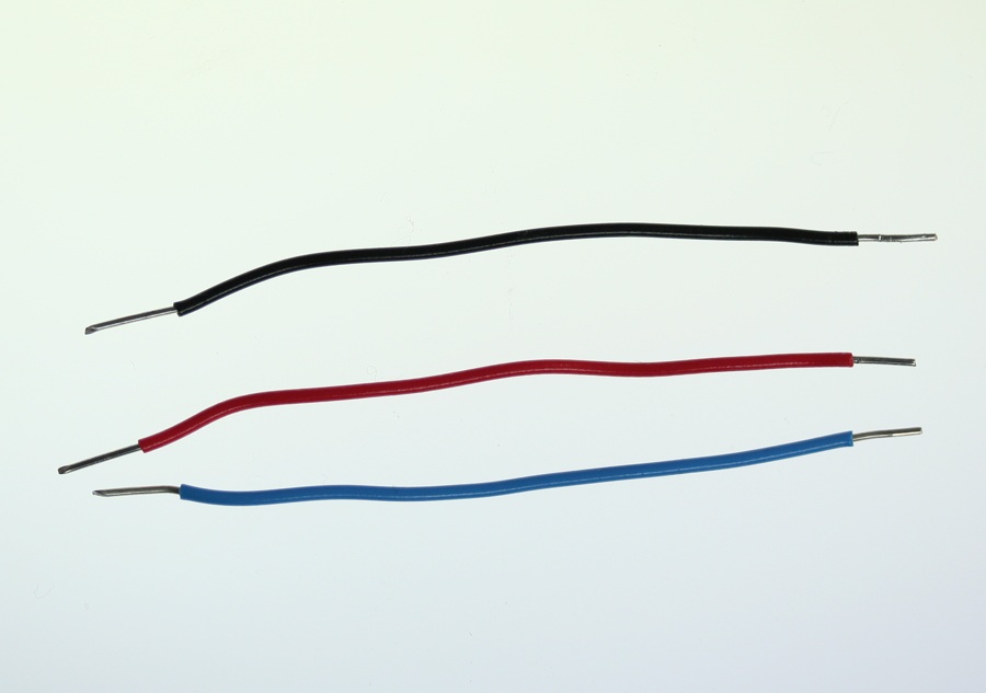
Things You’ll Need
Figure 1-3 are basically what you need for this lab.


Prepare the breadboard
Connect power and ground on the breadboard to power and ground from the microcontroller. On the Arduino module, use the 5V and any of the ground connections(Figure 4):


As shown in Figure5, the +3.3 volts and ground pins of the Arduino are connected by red and black wires, respectively, to the left side rows of the breadboard. +3.3 volts is connected to the left outer side row (the voltage bus) and ground is connected to the left inner side row (the ground bus). The side rows on the left are connected to the side rows on the right using red and black wires, respectively, creating a voltage bus and a ground bus on both sides of the board.
Add the LED
Related Video: DIY Serial protocol
Connect an LED and resistor to pin 11 of the Arduino through a 220-ohm resistor. If you prefer an audio output, you can use a speaker instead. Appropriate code changes will be mentioned below (Figure6-7):
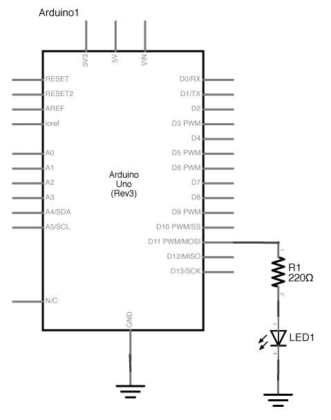
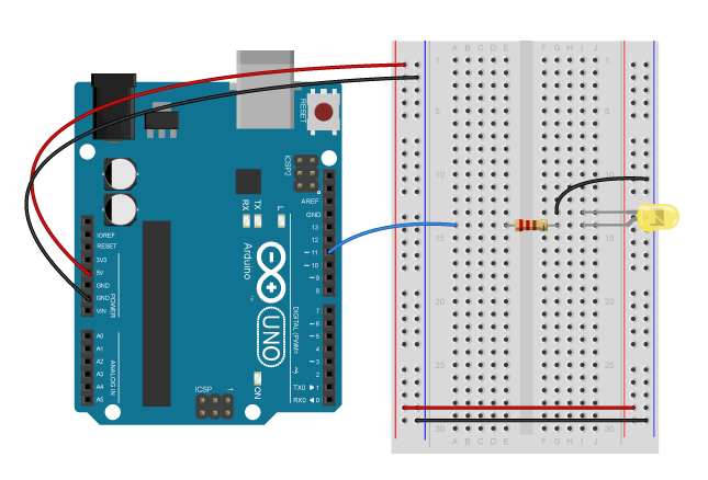
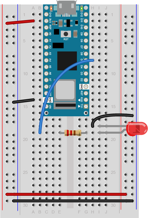
Figure 8: Breadboard view of an LED connected to digital pin 5 of an Arduino Nano. The Nano straddles the center of the breadboard in the first fifteen rows. The Nano’s voltage pin (physical pin 2) connects to the board’s voltage bus, and the Nano’s ground pin (physical pin 14) connects to the board’s ground bus. The LED is in the right center of the board, with its anode in one row and the cathode in the next. A 220-ohm resistor connects the LED’s anode to a wire connecting to digital pin 5. The LED’s cathode is connected to the ground bus.
Program the Microcontroller to Read Serial Input
Related Video: Serial.available()
To program the Arduino to read serial input, you use the Serial.available() command. The .available() command returns the number of bytes that are available in the Arduino’s serial buffer that you haven’t read yet. When there are bytes available, you can read them using Serial.read().
In the setup() function of your program, initialize serial communications using Serial.begin(). Set the LED’s pin to be an output using pinMode() as well. Then in the setup, check how many bytes are available in the serial buffer using Serial.available() like so:
void setup() {
  Serial.begin(9600);   // initialize serial communications
  pinMode(11, OUTPUT);  // set digital pin 11 to be an output, to control the LED
}

void loop() {
  if (Serial.available() > 0) {

  }
}
Interpret the Incoming Serial Bytes
Related Video: reading the bytes in Arduino
Inside the if statement that checks Serial.available(), you’ll interpret the bytes as they come in. First, read the incoming bytes using Serial.read(). The serial buffer is a First-in, First-out buffer, or a FIFO buffer, meaning that the first byte that the computer sends is the first byte that the Arduino can read:
Here’s how to read the incoming bytes and interpret them:
void loop() {
  if (Serial.available() > 0) {
    byte input = Serial.read();  // read first available byte into a variable
    if (input == 'H') {          // if the variable equals H, or ASCII 72
      digitalWrite(11, HIGH);     // turn on the LED
    }
    if (input == 'L') {          // if the variable equals L, or ASCII 76
      digitalWrite(11, LOW);      // turn off the LED
    }
  }
}
This sketch now reads the first available byte into the variable input, then evaluates the variable. If input is equal to 72, which is the ASCII letter H, it turns on the LED. If input equals 76, or ASCII L, it turns the LED off.
Note: What Do the Single Quotes Mean?
In the C programming language (and by extension, in Arduino, since Arduino based on C), you can put a single ASCII character in single quotes and the compiler will interpret it as its numeric value. This can be handy when you know you want to compare a byte to an ASCII character, but can’t remember the numeric value of the ASCII character.
Send Bytes to the Microcontroller
Related Video: uploading the sketch to the Arduino
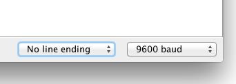
Once you’ve uploaded this to the board, open the serial monitor. If you’re using the Arduino Serial Monitor to read and write serial data, make sure the line ending tab is set to “no line ending” like so(Figure 9):
If you prefer to use a command line interface for serial communication, you can do that using the screen command.
Type H or L in the text input bar at the top, then hit enter. You should see the LED turn on when you send H, and turn off when you send L. You’ll notice that if you send lower case h or l, nothing happens. That’s because you didn’t check for those values. In ASCII, uppercase letters and lowercase letters each get different values. Uppercase H is 72, for example, but lowercase h is 104.
The serial monitor isn’t the only program that can send bytes to your microcontroller. Any program that can communicate over asynchronous serial communication can be used to send data. So if you’re using Processing, or Max/MSP, or node.js, you can control this simple Arduino program serially.
Change the Brightness of the LED Bytes Serially
The microcontroller reads all incoming bytes as values from 0 to 255. In the example above, you saw how to interpret those values as ASCII characters. But you can use the byte values any way you wish. Change the loop of your program as shown below:
void loop() {
  // put your main code here, to run repeatedly:
  if (Serial.available() > 0) {
    byte input = Serial.read();
    // use the value of the incoming byte to control the LED's brightness:
    analogWrite(11, input);
  }
}
Upload this new sketch and open the serial monitor. When you send characters now, what’s happening? The LED’s brightness might be jumping around, seemingly randomly. Lower case letters toward the end of the alphabet will make the LED slightly brighter, and uppercase ones toward the beginning will make it dimmer. The lower the value, the lower the brightness of the LED. a space, which is ASCII 32, will make the LED very dim, while a tilde (~), which is ASCII value 126, will make it brighter.
Related Video: reading a byte from the computer in Arduino
Advanced Serial Input: Parsing Numeric Strings
But what if you want to send an ASCII-encoded numeric string? Why doesn’t the LED turn on to full brightness when you type “255”? Even though you interpret the characters as one number, the Arduino interprets them as three bytes, with the values 50 (“2” = ASCII 50), 53 (“5” = ASCII 53), and 53. How do you get the Arduino to convert these strings as numbers?
You can use the Serial.parseInt() function to interpret ASCII numeric strings. This function will read all incoming bytes looking for a numeric character, and when it finds one, it will keep looking until it finds the next non-numeric character. Then it will interpret all the numeric characters it found as one number. Change your sketch’s loop as follows:
void loop() {
  // put your main code here, to run repeatedly:
  if (Serial.available() > 0) {
    int input = Serial.parseInt();
    // use the value of the incoming byte to control the LED's brightness:
    analogWrite(11, input);
  }
}
Then send in a numeric string, like 255 or 10. You should see the LED get much brighter with 255, and much dimmer with 10. If you send 0, the LED should turn off. Instead of interpreting your data byte-by-byte, .parseInt() is looking for strings of numbers and interpreting them. You can even give it multiple strings separated by non-numeric characters. Try the following strings:
10,127,255 0 255 0 12-250-3
You can separate your numbers however you wish. You could even look for multiple different numbers with multiple variables, like this:
void loop() {
  // put your main code here, to run repeatedly:
  if (Serial.available() > 0) {
    int red = Serial.parseInt();
    int green = Serial.parseInt();
    int blue = Serial.parseInt();
  }
}
With the code above, if you sent three comma-separated values, you’d be able to set the three variables red, green, and blue independently.
Serial.setTimeout()
You may notice that .parseInt() is slow to respond. It has a timeout that defaults to one second, waiting for incoming data. You can speed it up by using Serial.setTimeout() to set the timeout in milliseconds. In your setup, right after Serial.begin(), try a Serial.setTimeout(10) to set the timeout to 10 milliseconds. This is generally good for most programs that might be sending ASCII strings to the microcontroller.
Serial Control from Node.js
If you’re familiar with node.js and the node-serialport library, perhaps because you’ve already tried the Serial to node.js lab, upload the following Arduino sketch:
void setup() {
  // put your setup code here, to run once:
  Serial.begin(9600);
  Serial.setTimeout(10);
  pinMode(11, OUTPUT);
}

void loop() {
  // put your main code here, to run repeatedly:
  if (Serial.available() > 0) {
    char input = Serial.parseInt();
    // use the value of the incoming byte to control the LED's brightness:
    analogWrite(11, input);
  }
}
Now try the following node.js script (you’ll need to install node-serialport using npm as you did in the Serial to node.js lab). Save this as serialOutput.js:
// serial port initialization:
var SerialPort = require('serialport'); // include the serialport library
var portName = process.argv[2]; // get the port name from the command line
var myPort = new SerialPort(portName, 9600);// open the port

// these are the definitions for the serial events:
myPort.on('open', openPort); // called when the serial port opens

function openPort() {
  var brightness = 0; // the brightness to send for the LED
  console.log('port open');
  console.log('baud rate: ' + myPort.options.baudRate);

  // since you only send data when the port is open, this function
  // is local to the openPort() function:
  function sendData() {
    // convert the value to an ASCII string before sending it:
    myPort.write(brightness.toString());
    console.log('Sending ' + brightness + ' out the serial port');
    // increment brightness by 10 points. Rollover if < 255:
    if (brightness < 255) {
      brightness+= 10;
    } else {
      brightness = 0;
  }
}

// set an interval to update the brightness 2 times per second:
setInterval(sendData, 500);
}
Make sure the serial monitor in Arduino is closed, then run this by typing the following on the command line:
$ node serialOutput.js portname
Replace portname with the name of your serialport. When this runs, you should see the LED getting ten percent brighter every half a second, then go out when it reaches the brightest.