Introduction
Sensors convert various forms of physical energy into electrical energy, allowing microcontrollers to read changes in the physical world.
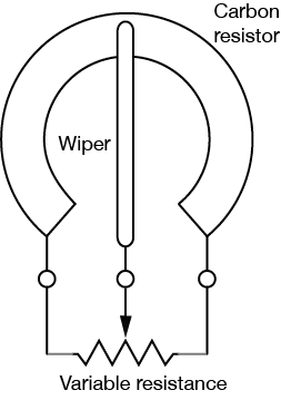
The simplest sensors read changes in mechanical energy, usually by moving electrical contacts. For example the pushbutton or switch (related video) converts mechanical energy (e.g, your finger’s press) into electrical energy by closing a connection between two metal contacts. The potentiometer (related video) shown in Figure 1 and Figure 2 is another sensor that reads mechanical energy changes: a metal contact called a wiper slides along a resistor, effectively short circuiting the resistor (related video) into two halves and creating a voltage divider circuit.

Although switches and pushbuttons typically only read an on state or an off state, most other sensors can read a wide range of possible states. In other words, they’re analog sensors, because they read a variable change. Whenever you use a new sensor, the first thing you need to understand is what the range is that it can read and deliver. When you’re using your sensor in an application, you need to know the range of possible values your application requires. Do you just need high, medium, and low (3 possible values), or a range from 0 to 10? Do you need a 100-point range? The range that you need depends on what your user can perceive. For example, if you’re making a lighting dimmer, and your user can only perceive about a dozen different light levels, then you don’t need to give her a sensor that can give her a 1000-point range of control.
Resistive Sensors
Related Video: Sensors – Survey 1
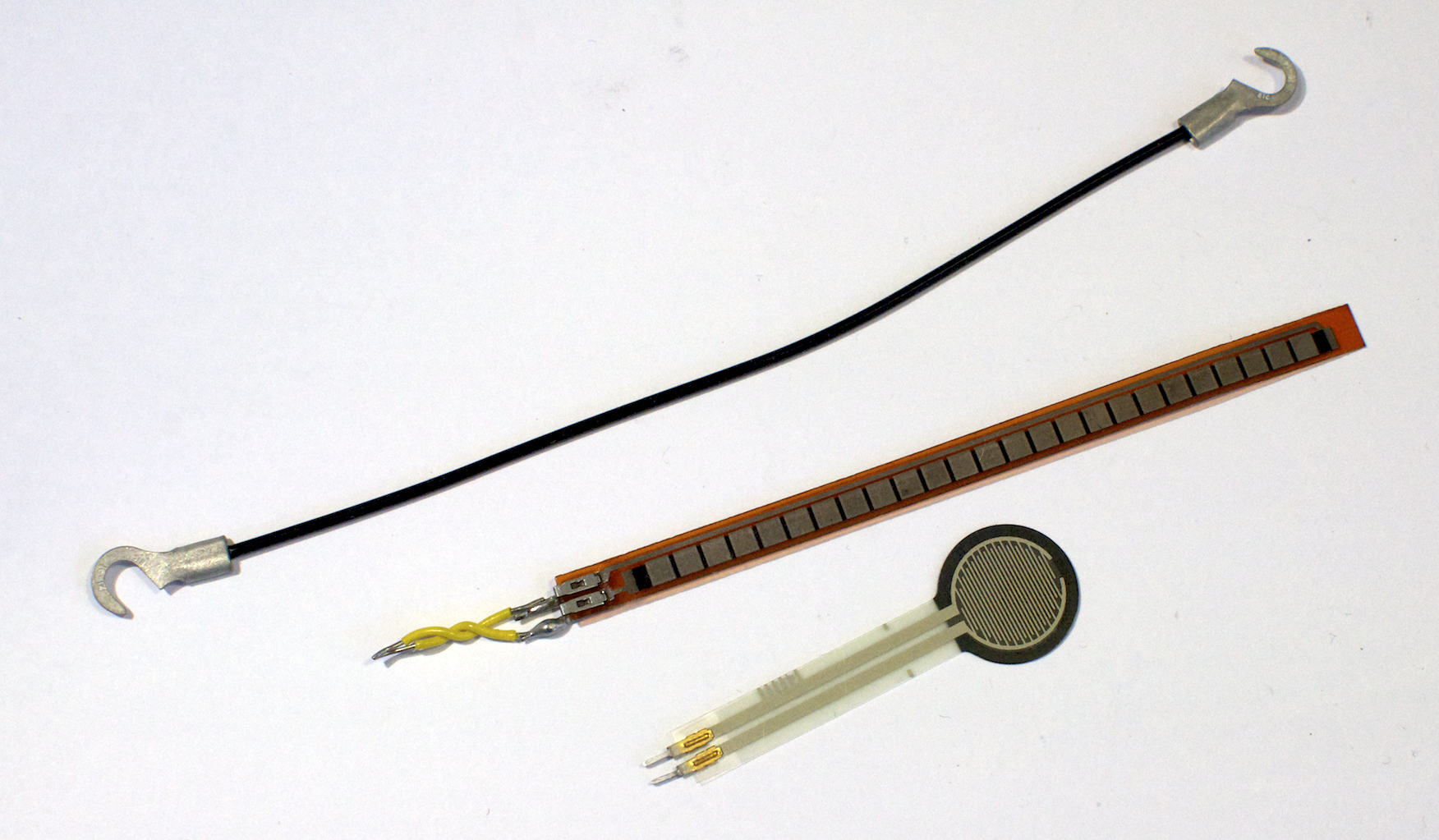
Many sensors work by converting the energy they read into a changing electrical resistance by using a variably resistive material at their heart. Examples of resistive sensors are shown in Figure 3. For example, force sensors and stretch sensors are made of a partially conductive rubber. When the rubber is stretched or compressed, the resistance change. Photoresistors or light dependent resistors change their resistance when exposed to a change in light energy. In order to read changes in resistance, you typically place these sensors in a voltage divider circuit , which converts the resistance change into a changing voltage.
Optical Sensors
Light is used in many sensors in a variety of ways. Light-emitting diodes, light-dependent resistors, and phototransistors can be combined to sense dust, measure distance, or determine reflected color. Light is also used in some ranging sensors to determine distance from a sensor to a target.
Ranging Sensors
Related video: Ranging Sensors
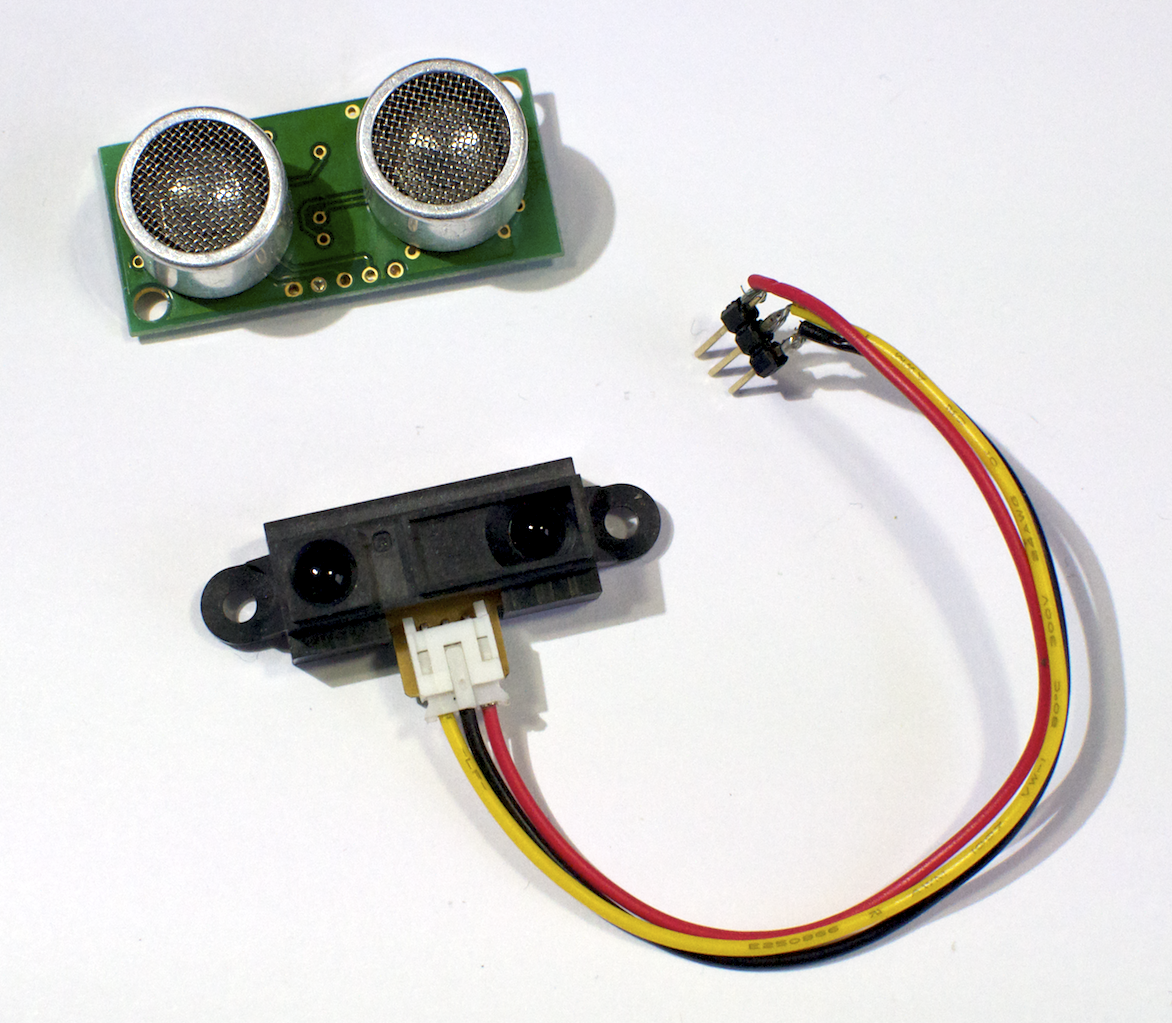
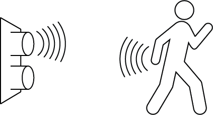
Many sensors measure movement or distance indirectly, by sending out a pulse of light or sound and reading the reflected signal when it bounces off a target as illustrated in Figure 5. These are called ranging sensors (Figure 4) because they read a range of distance.
MEMS Sensors
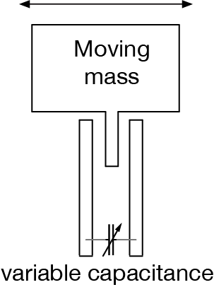
Still other sensors work by converting the energy they read into a change in capacitance. For example, accelerometers and other miniaturized electromechanical (MEMS) sensors typically have a tiny moving conductive mass at their core, suspended on tiny springs and surrounded on both sides by electrical contacts. Because the conductive mass is parallel to the outer contacts, a capacitance builds up between the contact. When the mass is moved, the capacitance changes between the two sides, effectively creating two variable capacitors as illustrated in Figure 6. That variable capacitor is then placed in a resistor-capacitor circuit to convert the change in capacitance into a changing voltage.
Digital Interface Sensors
Related video: Sensors – Interfacing
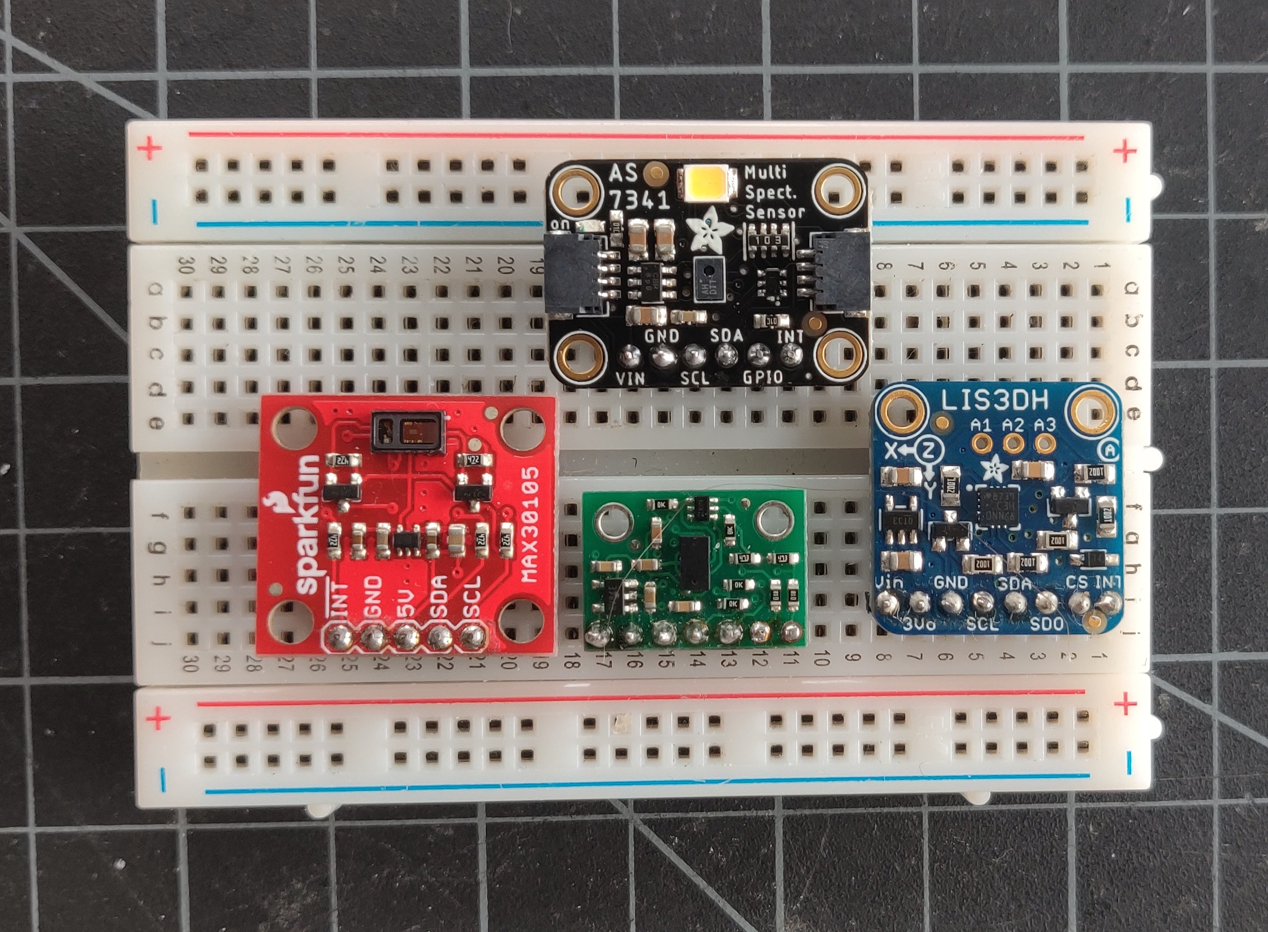
Other than switches and variable resistors, most sensors you buy are integrated circuits that include the resistance-to-voltage or capacitance-to-voltage circuit and provide you with an analog voltage output. Some will even include an analog-to-digital converter and provide you with a serial data interface, either I2C, SPI, or asynchronous serial, so that you can connect the sensor to the serial ports of your microcontroller. Still others will provide a changing pulse output, or pulse width modulation (PWM) output, where the width of the pulse represents the sensor value.
Data Sheets
When you shop for sensors, you need to look at the data sheet to learn how they operate. The data sheet will usually include the following essential facts:
- a text description of the sensor and its operation;
- a pin diagram to tell you what pins perform what functions;
- a table of electrical characteristics that tells you what the supply voltage is, what the operating current is, and what the output is, along with other electrical and physical properties;
- a graph or conversion formula that relates the input energy to the output energy;
- a mechanical description of the sensor itself.
Some datasheets will include other information as well, such as application circuits, reliability data, and so forth.
You should follow the datasheet’s guideline for sensor operation. Don’t exceed the maximum or minimum operating voltage, and make sure to supply adequate current to operate the sensor. Avoid supplying too much current, because the excess current will get turned into heat, which often changes the sensor’s operating characteristics. Make sure you understand the sensor’s interface. Be clear on whether it’s an analog electrical property like resistance, capacitance or voltage, or a digital serial data interface. Look for typical application circuits and microcontroller code samples online if you can find them.
Using a Sensor With a Microcontroller
Related video: Sensors – Testing
Once you understand how a sensor works and what its output will be, you should connect it to your microcontroller and write a simple program to read the output. Don’t jump right into writing a complex program. Write the smallest program necessary to read the sensor’s changing values and output them for debugging purposes. Then put the sensor in the physical context in which you plan to use it and read the output values in action. The range that a sensor can read will change depending on the specific conditions or actions that you plan to read. So make sure the physical setting of the sensor is as close to reality as possible in order to test it. Once you know the range of values that it’s going to output in those conditions, then you can write a function to convert the sensor’s raw output range into a range you can use. Depending on the context, you probably won’t get the full output range that the sensor is capable of delivering. So your conversion function should be based on the range you’re actually seeing, not the total range.
You probably don’t need to convert the sensor’s readings into its output voltage or its physical property. For example, if you’re using a force sensing resistor, you probably don’t need to know how many Newtons of force are being exerted on the sensor, or what the output voltage is. Instead, you probably just need to know whether someone is pressing gently, firmly, or really firmly against the sensor. Perhaps you just need a range from 0 to 10. When you write your conversion function, consider what the relevant result is for you, and write a function that delivers that result.