Introduction
In order to make two devices communicate, whether they are desktop computers, microcontrollers, or any other form of computer, you need a method of communication and an agreed-upon language. Serial communication is one of the most common forms of communication between computers. These notes explain the basics of getting two computers talking to each other using Asynchronous Serial communication.
To get the most out of these notes, you should know what a microcontroller is and have an understanding of the basics of microcontroller programming. You should have some understanding of programming a personal computer as well, ideally in a language that can access the serial ports of the computer, like p5.js with p5.webserial, p5.js with p5.serialport, the Processing programming environment, node.js programming environment, Python, or Java.
Serial Communication Agreements
Related video: Asynchronous Serial communication – Intro
Communicating serially involves sending a series of digital pulses back and forth between devices at a mutually agreed-upon rate. The sender sends pulses representing the data to be sent at the agreed-upon data rate, and the receiver listens for pulses at that same rate. This is what’s known as asynchronous serial communication. There isn’t a common clock in asynchronous serial communication; instead, both devices keep time independently, and either send or listen for new bits of data at an agreed-upon rate.
In order to communicate, the two devices need to agree on a few things:
- the rate at which data is sent and read
- the voltage levels representing a 1 or a 0 bit
- the meaning of those voltage levels; is a high voltage 1 and a low voltage 0, or is the signal inverted so that a low voltage is a 1 and high voltage is 0?
For example, let’s say two devices are to exchange data at a rate of 9600 bits per second. First, you would make sure there’s an agreed upon high and low voltage supplying each device, then you’d make three connections between the two devices:
- a common ground connection, so both devices have a common reference by which to measure voltage;
- one wire for the sender to send data to the receiver on (transmit line for the sender);
- one wire for the receiver to send date to the sender on (receive line for the sender).
Since the data rate is 9600 bits per second (sometimes called 9600 baud), the receiver will read the voltage on its receive wire every 1/9600th of a second. It will interpret that voltage reading as a new bit of data. If the voltage is high (typically +5V or +3.3V in the case of most microcontrollers), it will interpret that bit of data as a 1. If it is low (typically 0V), it will interpret that bit of data as a 0. By interpreting the bits of data over time, the receiver can get a detailed message from the sender. at 9600 baud, for example, 1200 bytes of data can be exchanged in one second.
What Do the Serial Voltage Changes Mean?
Related video: Serial 2 – Analyzer & ASCII
Let’s look at a byte of data being exchanged. Imagine you want to send the number ninety (90) from one device to another. First, you have to convert the number from the decimal representation, “90,” to a binary representation. In binary, ninety is 01011010. So your sending device will pulse its transmit line as shown in Figure 1:
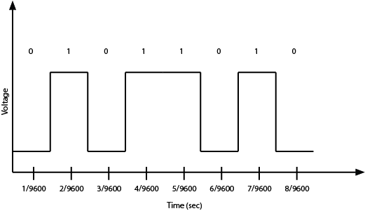
As you might guess from this diagram, both devices also have to agree on the order of the bits. Usually the sender sends the highest bit (or most significant bit) first in time, and the lowest (or least significant bit) last in time. As long as you have an agreed upon voltage, data rate, order of interpretation of bits, and agreement on what the voltage levels mean, you can exchange any data you want serially.
For the data transmission above, a high voltage indicates a bit value of 1, and a low voltage indicates a voltage of 0. This is known as true logic. Some serial protocols use inverted logic, meaning that a high voltage indicates a logic 0, and a low voltage indicates a logic 1. It’s important to know whether your protocol is true or inverted. For example, RS-232, which was the standard serial protocol for most personal computers before USB came along, uses inverted logic.
UART? USB? CDC?
The asynchronous serial communication you’ll be using here is sometimes referred to as TTL serial (transistor-transistor logic), and it’s not an inverted serial protocol. In TTL serial communications, high voltage means logic 1, and low voltage means logic 0. Most processors on the market today are equipped with one or more Universal Asynchronous Receiver-Transmitters, or UARTs, for communicating this way.
Most personal computers do not have an asynchronous serial port anymore. Instead, they have USB ports. USB stands for Universal Serial Bus, and it’s a slightly different serial protocol that allows multiple devices to communicate over the same wires. This configuration is known as a bus configuration. USB is a complex protocol that can support many different classes of devices, from human interface devices (HID) like mice and keyboards to mass storage devices to cameras, and more. Because so many devices still use asynchronous serial communication, USB includes a Communications Device Class (CDC) that supports asynchronous serial communication. Devices that include a USB-to-serial converter will show up as serial ports to your computer when you plug them in. Many microcontroller boards, including the Arduino boards, include a USB-to-serial converter to communicate with your computer in this way. When you plug them in, any program that can read serial ports will list the connected Arduino in the list of serial ports.
Some microcontroller boards, like the Arduino Uno, have a separate USB-to-serial chip on board, which allow them to appear as a USB serial device to your personal computers. Others, like the Arduino Nano 33 IoT, are USB-native, meaning that they can act as a USB device without a separate chip on board. These types of boards will appear to your personal computer as a USB serial device when their sketch is running, and will temporarily disappear when they reset. The advantage of a USB-native microcontroller is that they can also be programmed to behave as other USB devices, like MIDI, Mouse or Keyboard.
Serial Buffers and Control of the Port
Once you’ve got the computer and the microcontroller connected, you’ll need to write a program to address the serial ports. The process is slightly different on the different microcontrollers, but there are some elements common to all of them.
All processors that have a UART (this includes personal computers and microcontrollers, and most embedded boards like the Beaglebone Black and Raspberry Pi as well) have an area in memory where they store incoming data from the serial ports called a serial buffer. Because of this, they can do other tasks while waiting for data to come in, and act on the data from the buffer after it comes in.
Serial ports can only be controlled by one program at a time. For microcontrollers that aren’t running an operating system, this is simple; whatever program is running on the controller gets the serial port. On computers with an operating system, you might have multiple programs running, but only one can control a given serial port at any one time. For example, if you have a laptop connected serially to an Arduino, and the Arduino IDE’s Serial Monitor is open, then no other program can read from that serial port. You’d need to close the serial monitor to open the port from Processing or any other application. Related video: Only one program can control the port
Once you’ve got the serial port open, any bytes sent by the connected device will be available to your program in the order that they were sent. As you read each byte, the byte is removed from the serial buffer. This is why serial buffers are also called First-In, First-Out or FIFO buffers.
For more on sending serial from Arduino to another computer, see one of these labs, depending on the programming language you plan to communicate with:
- Serial Input to p5.js with the p5.webserial library
- Serial Input to P5.js Using the p5.serialport library
- p5.serialport and p5.webserial Compared
- Serial Input to Processing
- Serial Input to node.js
When two devices are communicating serially, they can’t read each other’s program logic. They can only read what the other device has said. Because of this, you need to make sure that the programs on both sides are using the same communications protocol. This is the highest level of agreement in serial communications: both sides need to agree on what the bytes being sent mean, and in what order they are being sent. For more on this, see the serial data interpretation notes.