Introduction
Stepper motors are useful for when you need to rotate a full 360 degrees, but need to position your motor at a particular angle. What follows is a more detailed introduction to unipolar and bipolar stepper motors and how to control them from a microcontroller. In order to get the most out of these notes, you should know something about how electricity works, and you should know the basics of how a microcontroller works as well. You should also understand how transistors are used to control high-current loads. You should also understand how DC motors work.
As you learned in the introduction to motors, stepper motor is a motor controlled by a pair of electromagnetic coils. The center shaft has a series of magnets mounted on it, and the coils surrounding the shaft are alternately given current or not, creating magnetic fields which repulse or attract the magnets on the shaft, causing the motor to rotate.
Related Videos
- Types of Stepper Motors
Unipolar Steppers and Transistor Arrays - Bipolar Steppers and H-Bridges
- Dedicated Stepper Drives
There are two basic types of stepper motors, bipolar steppers and unipolar steppers. A bipolar is the simpler kind of stepper motor; it’s simply two coils, and has four wires. Depending on which coil you put power through, and which direction you send the power in, you step the motor one step forward or back. A unipolar stepper is slightly more complex. It also has two coils, but the centers of the coils are joined in a single junction. This effectively creates four coils, depending on how you put electrical energy through it.
If you’re looking for sources of stepper motors and stepper motor drivers, you’ll find many motors and drivers at Pololu, Adafruit, Sparkfun, and the other usual hobbyist electronics retailers. Octopart will also give you wide variety of retailers for steppers.
Bipolar stepper motors
A bipolar stepper motor usually has four wires coming out of it. It has two independent coils. Figure 1 shows a typical bipolar stepper with four wires. In the center is the motor’s shaft, which has a cog-like rotor on it. Each tooth of the cog is magnetized, and every cog’s magnetic polarity is opposite the one next to it.When you put voltage and current through one coil, it turns the central rotor a few degrees, because the magnets on the rotor are attracted to the magnetic field generated by the coil. When you turn that coil off and the other one on, the motor moves a few degrees more.
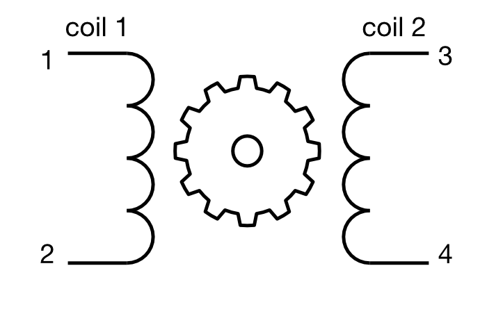
To use a bipolar stepper, you need to know which wire is connected to which coil. You can determine this by measuring the resistance between pairs of wires. When you’ve got the leads of your meter connected to two wires on opposite coils, you should see infinite resistance, or no continuity. When your meter leads are on the same coil, you’ll be able to read the coil’s resistance. The two coils should have the same resistance.
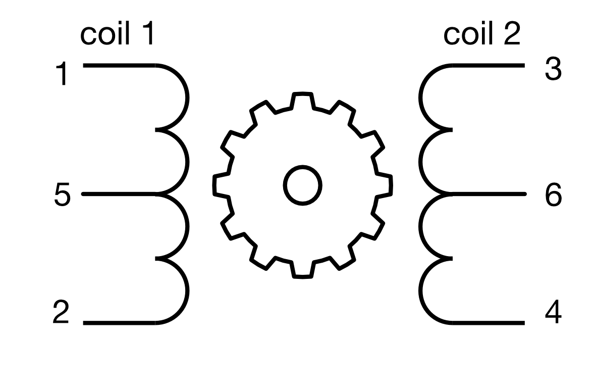
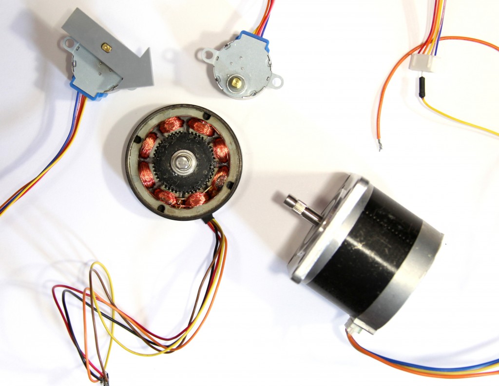
Some bipolar steppers have a center connection on each coil. This allows for finer control over the motor, by treating each half coil as its own coil, as shown in Figure 2. These center connections can be joined to turn a 6-wire bipolar stepper into a unipolar stepper as well. Figure 3 shows the inside of a typical bipolar stepper motor.
Like other motors, stepper motors require more power than a microcontroller can give them, so you’ll need a separate power supply for them. Ideally you’ll know the voltage and load current from the manufacturer. If not, get a variable DC power supply, apply the minimum voltage (hopefully 3V or so), apply voltage across two wires of one coil (e.g. 1 to 2 or 3 to 4) and slowly raise the voltage until the motor is difficult to turn. It is possible to damage a motor this way, so don’t go too far. Typical voltages for a stepper might be 5V, 9V, 12V, 24V. Higher than 24V is less common for small steppers, and frankly, above that level it’s best not to guess.
Unipolar Stepper Motors
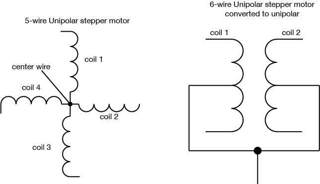
Unipolar steppers motor have five or six wires. The five-wire version has four coils which are all connected on one pole. Six-wire motors are actually bipolar steppers with two coils divided by center connections on each coil, as described above. The center connections of the coils are tied together as shown in Figure 4 and sometimes used as the power connection.
Common Stepper Motor Types
There are two common families of stepper motor that you’ll encounter: NEMA motors and can-stack or tin-can steppers. The labs on this site can work with either. NEMA motors are designed according to a standard set by the US National Electrical Manufacturers Association. These are high-quality motors, and usually the more expensive that you’ll find. The number in a NEMA motor’s designation indicates the motor’s size. A NEMA-11 motor, for example, has a mounting face that’s 1.1 inches square; NEMA-23 is 23 step motor is 2.3 inches square and so forth. Electromate.com has a detailed explanation of NEMA motors if you ‘d like more detail.
Can-stack steppers are typically smaller and more cheaply made, mounted in a simple can, often with gears on top to increase torque and steps per revolution, and decrease speed. They’re often used in disk drives, motorized lens optics, and other industrial applications. The first number in the spec for these indicates the can’s diameter in millimeters. A 28BYJ-48 motor has a 28mm diameter can. A 24BYJ-48 has a 24mm can size, and so forth. Melissa Zheng has a good explanation of can-stack stepper motor specs.
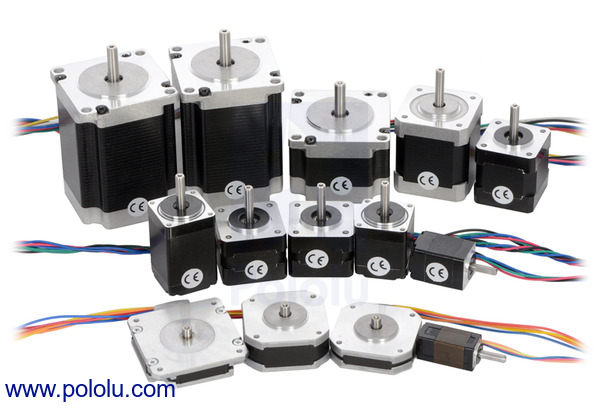
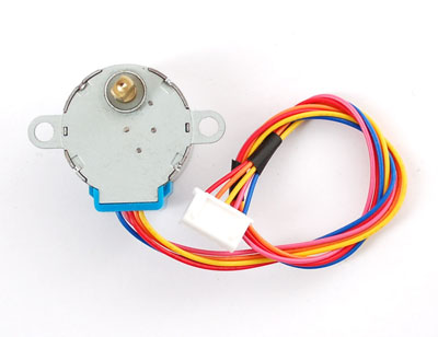
Figure 5 shows a variety of NEMA-style steppers. Figure 6 shows a 28BYJ-48 can-stack stepper.
Control of Stepper Motors
To control the stepper, apply voltage to each of the coils in a specific sequence. Both types of stepper motor can be controlled with a motor driver (related video). The sequence would go like this:
| Step | Wire 1 | Wire 2 | Wire 3 | Wire 4 |
|---|---|---|---|---|
| 1 | high | low | high | low |
| 2 | low | high | high | low |
| 3 | low | high | low | high |
| 4 | high | low | low | high |
To step the motor, you change the pins in the order shown in Table 1. With each step, the motor will move forward or backward one increment. Once you have the motor stepping in one direction, stepping in the other direction is a matter of doing the steps in reverse order.
It’s good practice when you wire a stepper up for the first time to write a program to step it slowly, one step at a time, using the steps above. That way you can see if you got the wiring right. If you did, the stepper should turn step by step in one direction. If you didn’t, it may step in unpredictable ways.
A stepper motor’s position is not absolute. You have to know where the motor started (usually measured with an external sensor) and how many degrees per step. Then you count the steps and multiply by that many degrees. So for examples, if you have a 1.8-degree stepper, and it’s turned 200 steps, then it’s turned 1.8 x 200 degrees, or 360 degrees, or one full revolution.
The circuits for controlling a unipolar stepper or a bipolar stepper are very similar. In both cases, you have four ends of coils that go to the four outputs of the driver. The difference is that for the unipolar, you also have a common center wire. That wire can be attached to the same motor voltage supply that feeds the driver, or it can be left disconnected. If you do the latter, you’re treating the unipolar motor as if it had two separate coils — in other words, as if it were a bipolar stepper.
H-bridge Stepper Drivers
There are a couple of different types of stepper motor drivers. The oldest use four transistors, treating each wire as if it were a motor itself. If you take wire 1 high and wire 2 low, coil turns one direction. Take wire 1 low, and wire 2 high, and the coil turns the other direction. The same principle applies to the other coil. This can be done with individual Darlington transistors or MOSFETs, or it can be done with a transistor array like the ULN2004.
The four-transistor approach is essentially an H-bridge, and you could use two H-bridges to control a stepper. The TB6612FNG dual motor driver that you saw in the H-bridge lab is a dual H-bridge designed for this purpose. You’ll see it in action in the H-bridge stepper motor lab. There is an older H-bridge that only operates on 5V, the L293D, which you will encounter from time to time. This driver does not work with the Arduino Nano 33 IoT and other 3.3V boards, but it’s common enough that it’s useful to know that it can be replaced with a TB6612FNG.
With an H-bridge style driver, you know what you’re getting: take the input 1 HIGH and input 2 LOW, and you create a voltage difference between outputs 1 and 2. It’s conceptually easy, but requires more thinking and planning when you are programming the stepper. Fortunately, there is a Stepper library for Arduino that simplifies this somewhat.
Step & Direction Stepper Drivers
More modern stepper drivers have just two control pins, one for step and one for direction. They also feature configuration pins that let you set the step pin to move the motor a full step, a half step, or less. This is called microstepping, and you can find stepper drivers that will work as low as 1/256th of a step. This allows finer control over the stepper motor.
Step & direction drivers simplify control of a stepper because they only require two signals from a microcontroller: take the direction pin high or low to turn the motor’s direction one way or the other. Then pulse the step pin. With each pulse, the motor should step in the direction set by the direction pin. You can run these kinds of steppers without a library. You’ll see these drivers in the step & direction stepper driver lab.
There are a number of step & direction motor drivers available. For example, ther STSPIN220 from ST microelectronics works in the 1.8-10V range. the A4988 handles motors in the 8-35V range. Trinamic’s drivers, also sold on breakout boards by Watterott as SilentStepStick boards, control a wide range of voltages and are designed to reduce noise. Allegro’s A4988 and Monolithic’s MP6500 and Texas Instruments’ DRV88xx line are also good driver lines to look at. Here’s a comparison chart for many of these lines, on breakout boards from Pololu. Table 2 is a summary of a few other step & direction drivers.
In picking a step & direction driver, the first questions to ask are:
- Is my motor’s rated voltage in the driver’s Motor Voltage range?
- Is my motor’s rated current less than the driver’s Max. Motor Current range?
- Is my microcontroller’s operating voltage in the driver’s Control Voltage range?
| Driver | Type | Motor Voltage | Max. Motor Current | Control Voltage | Microsteps | Price (as of Jun. 2022) |
|---|---|---|---|---|---|---|
| A4988 Black Edition | Step & direction | 8-35V | 1.1A | 3-5.5V | 1/16 | $13.95 |
| STSPIN220 | Step & direction | 1.8-10V | 1.1A | 1.8-5.5V | 1/256 | $7.45 |
| TMC2130 | Step & direction, SPI | 5.5-45V | 1.2A | 3.3-5V | 1/256 | $10.68 |
| TMC2209 | Step & Direction, UART | 4.75-28V | 1.4A | 3.3-5V | 1/256 | $16.03 |
| TMC2208 | Step & Direction, UART | 4.75-36V | 1.2A | 4.6-5.25V | 1/256 | $9.58 |
| TMC2100 | Step & Direction | 5.5-45V | 1.2A | 3.3-5V | 1/256 | $9.28 |
| TB6612FNG | Dual H-Bridge | 15V | 1.2A | 2.7–5.5V | – | $5.50 |
| EasyDriver | Step & Direction | 6-30V | 700mA | 3-5.5V | 1/8 | $16.95 |