Introduction
Stepper motors are motors that have multiple coils in them, so that they can be moved in small increments or steps. The common feature to all stepper motors is that they have two coils in the motor rather than one. You control the stepper by energizing one coil, then reversing its polarity, then doing the same to the other coil. To do this, you can use a dual H-bridge driver like the TB6612FNG that you used in the DC motors and H-bridge lab. This lab shows you how to set up stepper motor using an H-Bridge.
What You’ll Need to Know
To get the most out of this lab, you should be familiar with the following concepts. You can check how to do so in the links below:
- How to solder up a connector
- Electronic components
- How DC Motors work
- How Stepper Motors work
- How to use transistors to control high current loads with Arduino
- What is an H-Bridge and how it works
- What is an Arduino Library
Things You’ll Need

Arduino Nano 33 IoT 
A solderless breadboard with two rows of holes along each side. 
Flexible jumper wires. 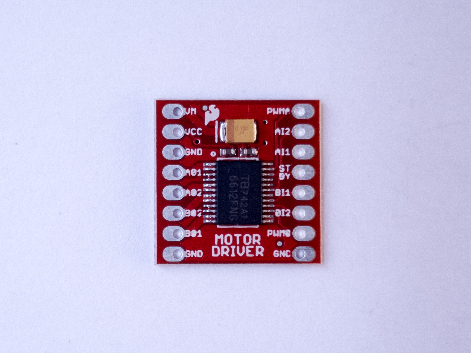
Motor Driver (H-bridge), model TB6612FNG 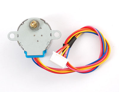
a stepper motor 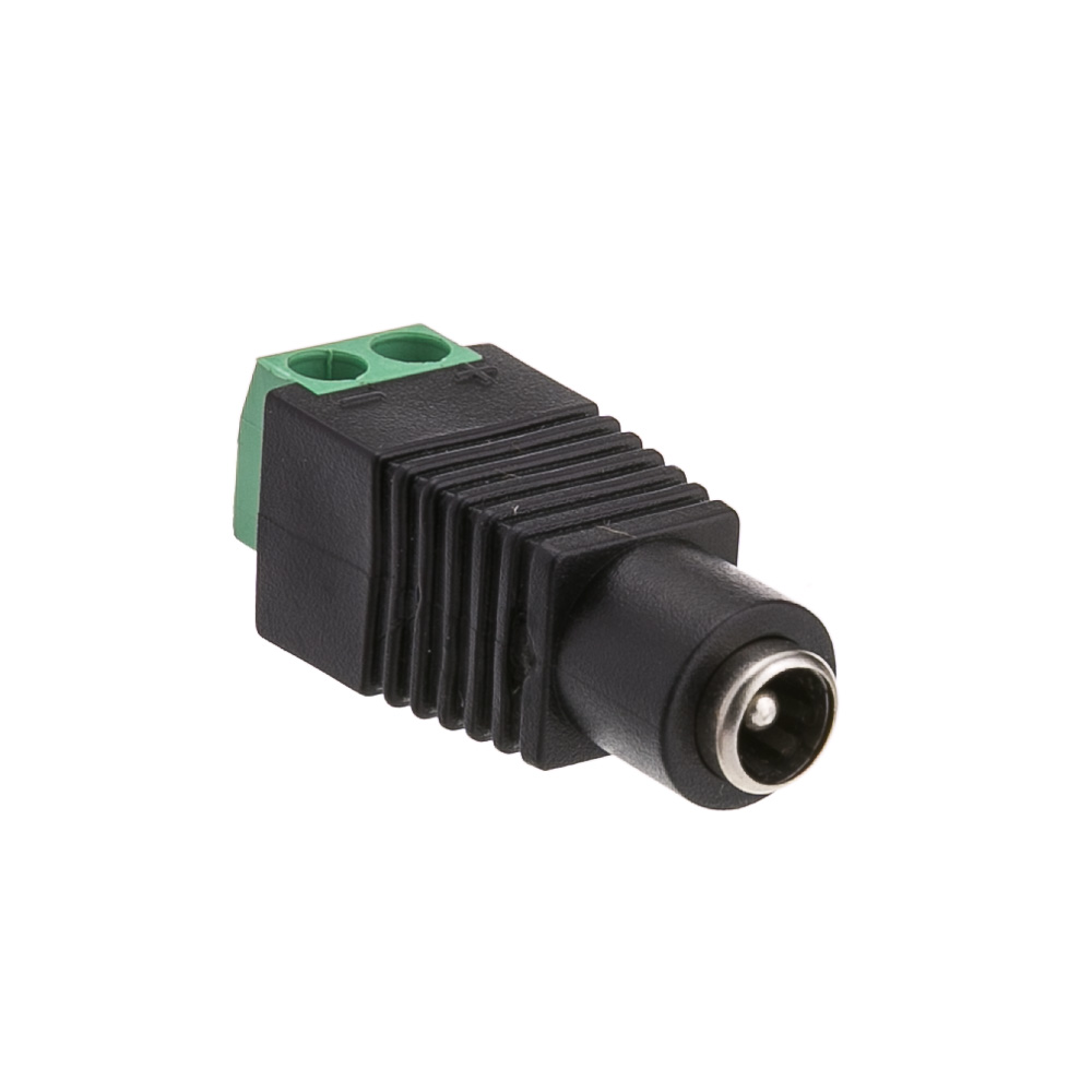
A DC Power Jack 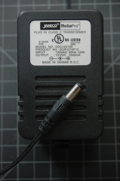
DC Power Supply 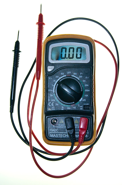
Multimeter. You’ll need this to check the coils.
The motor shown in the images here is a 5V Small Reduction Stepper Motor, 32-Step, with 1:16 Gearing. The driver is a Toshiba TB6612FNG. There’s a Sparkfun breakout board, an Adafruit breakout board, and a Pololu breakout board for this part as well. The principles in this lab, and the library used, will work with other stepper motors and dual H-bridge drivers as well, though you will have to make some modifications depending in which parts you are using.
Good Safety Practice
When you’re working with motors, you’re often dealing with high voltage, high current, or both. You should be extra careful never to make changes to your circuit while it is powered. If you need to make changes, unplug the power, make your changes, inspect your changes to be sure they are right, and then reconnect power.
It’s also a good idea to disconnect your motor from your circuit before uploading new code to your microcontroller. Often the current draw of the motor will cause the microcontroller to reset, and cause uploading problems. To avoid this, disconnect your motor before uploading, and reconnect it after uploading.
Because motors consume a lot of current when they start up, it’s common to add a decoupling capacitor of 10-100 µF near the voltage input to your driver and/or microcontroller. You’ll see this in the figures below. It will smooth out any voltage changes that occur as a result of the motor’s changing current consumption.
Prepare the breadboard
Connect power and ground on the breadboard to power and ground from the microcontroller. On the Arduino module, use the 5V or 3.3V (depending on your model) and any of the ground connections, as shown in Figures 9 and 10.

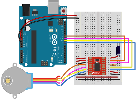
Figure 9 shows an Arduino Uno on the left connected to a solderless breadboard, right. The Uno’s 5V output hole is connected to the red column of holes on the far left side of the breadboard. The Uno’s ground hole is connected to the blue column on the left of the board. The red and blue columns on the left of the breadboard are connected to the red and blue columns on the right side of the breadboard with red and black wires, respectively. These columns on the side of a breadboard are commonly called the buses. The red line is the voltage bus, and the black or blue line is the ground bus.

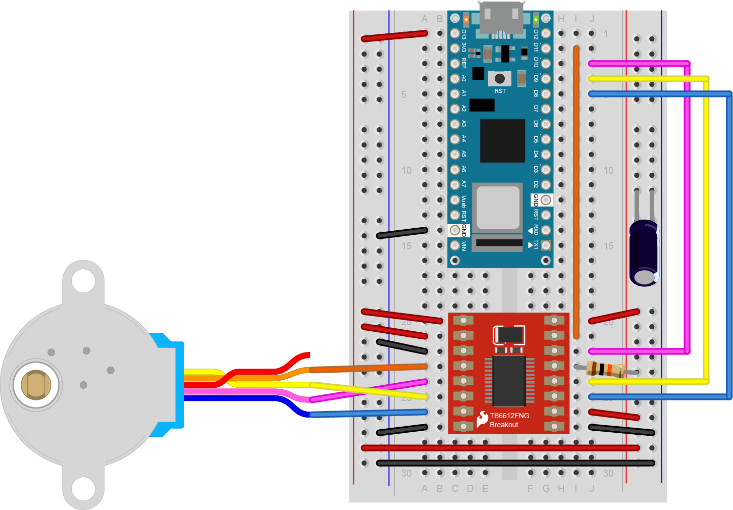
As shown in Figure 10, the Nano is mounted at the top of the breadboard, straddling the center divide, with its USB connector facing up. The top pins of the Nano are in row 1 of the breadboard.
The Nano, like all Dual-Inline Package (DIP) modules, has its physical pins numbered in a U shape, from top left to bottom left, to bottom right to top right. The Nano’s 3.3V pin (physical pin 2) is connected to the left side red column of the breadboard. The Nano’s GND pin (physical pin 14) is connected to the left side black column. These columns on the side of a breadboard are commonly called the buses. The red line is the voltage bus, and the black or blue line is the ground bus. The blue columns (ground buses) are connected together at the bottom of the breadboard with a black wire. The red columns (voltage buses) are connected together at the bottom of the breadboard with a red wire.
Made with Fritzing
How the Stepper Motor Works
A stepper motor is basically two motor coils in one motor, which allows you to turn the motor in steps. For more on this, see this stepper motor page.
The motor shown in this lab, a 5V Small Reduction Stepper Motor, 32-Step, with 1:16 Gearing, is typical of a class of stepper motors you can find using the designation 28BYJ-48. They come in a few varieties. There are 5V and 12V models, and there are versions like the one shown here, that have a gearbox on the top to increase their torque and increase the number of steps per revolution. The un-geared models have as few as 32 steps per revolution. This model has 32 steps per revolution and a 1/16 reduction gear box, giving it 32 * 16, or 512 steps per revolution. You can find models with an even higher reduction as well.
A stepper motor like this one has two coils to control it as shown in Figure 11. Each coil has a center connection as well, and the center connections are joined together, which is what makes this a unipolar stepper. If you don’t connect the center connection, then the motor will work like a bipolar stepper, each coil operating independently. This is how you’ll use it for this exercise. Each coil will connect to one control channel of the motor driver. The pink and orange wires are connected to the first coil. They will connect to one channel of the motor driver, while the yellow and blue wires are the other coil, and will connect to the other channel of the bridge (channel B). In this case, the red wire, pin 1, will not be used.

A bipolar stepper motor typically omit the red wire and just have two independent coils. A bipolar model like this 3.9V NEMA-8 stepper from Pololu would also work with this lab.
Check the Motor Coils’ Resistance
The wiring pattern in Figure 11 is typical, for the 28BYJ-48 motors. Nonetheless, it’s a good idea to check the wiring by measuring the coil resistance. The motor shown here has a coil resistance (impedance) of about 42 ohms. For a bipolar motor, each pair of coils (e.g. blue and yellow, orange and pink) would give you the motor’s rated coil resistance. Since this is a unipolar motor, you should read approximately 22-24 ohms across red and each of the other wires, and about 42-45 ohms across each pair (blue-yellow and orange-pink).
The sequence of the wires on the motor’s connector may vary from one manufacturer to another, so it’s a good idea to measure the resistance, then write down the pin order for reference later on.
How The Motor Driver Works
The TB6612FNG motor driver can handle a motor supply voltage up to 15V, and it operates on a logic voltage of 2.7–5.5V. It can control an output current of 1.2A. It has two motor driver circuits, each with two logic inputs and two motor outputs. Each motor driver has a PWM input, because they are expected to be used for speed control for the motor by pulse width modulating this pin. You won’t be using the PWM pins for this exercise though. There’s also a Standby pin that you have to connect to voltage through a 10-kilohm pullup resistor to activate the driver circuits.
The motor driver has the following pins. The pin numbers shown here are for the Sparkfun breakout board. The order of the pins will be different for the Adafruit and Pololu boards. The pins are numbered here in a DIP fashion, in a U-shape from top left to bottom left, then bottom right to top right. The list below describes the pins in numeric order.
- VMOT – motor voltage supply input, up to 15V.
- Vcc – logic voltage supply input, 2.7-5.5V
- Gnd – ground
- AO1 – A channel output 1. This is the first motor terminal for the first motor driver
- AO2 – A channel output 2. This is the second motor terminal for the first motor driver
- BO2 – B channel output 2. This is the second motor terminal for the second motor driver
- BO1 – B channel output 1. This is the first motor terminal for the second motor driver
- Gnd – ground
- Gnd – ground
- PWMB – B Channel PWM Enable. This pin controls the speed for channel B, regardless of the channel’s direction
- BI2 – B channel input 2. This controls B channel output 2. To control that pin, take this pin HIGH or LOW.
- BI1 – B channel input 1. This controls B channel output 1. To control that pin, take this pin HIGH or LOW.
- Stdby – enables both drivers when you take it HIGH and disables them when you take it LOW
- AI1 – A channel input 1. This controls A channel output 1. To control that pin, take this pin HIGH or LOW.
- AI2 – A channel input 2. This controls A channel output 2. To control that pin, take this pin HIGH or LOW.
- PWMA – A Channel PWM Enable. This pin controls the speed for channel A, regardless of the channel’s direction
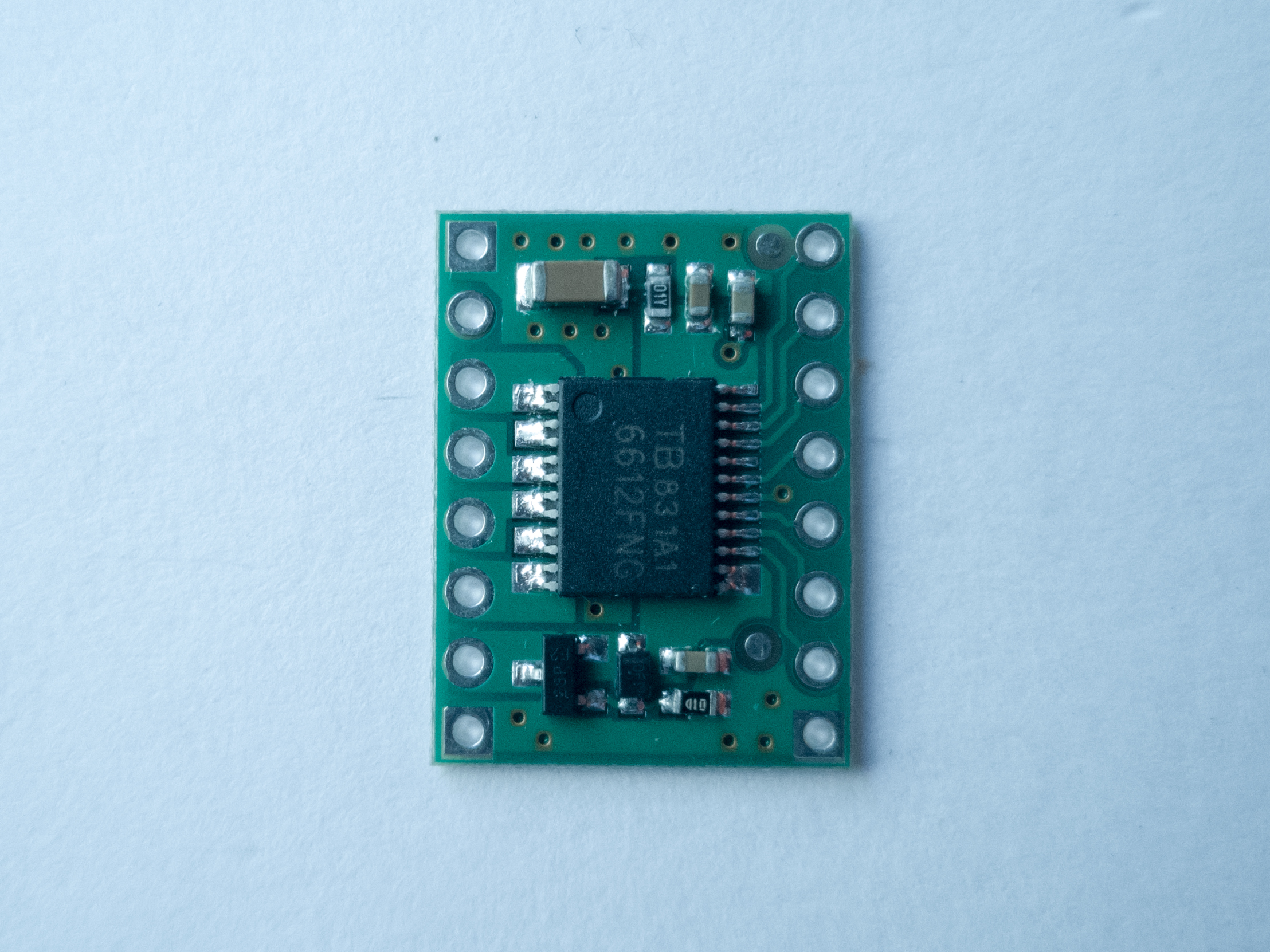
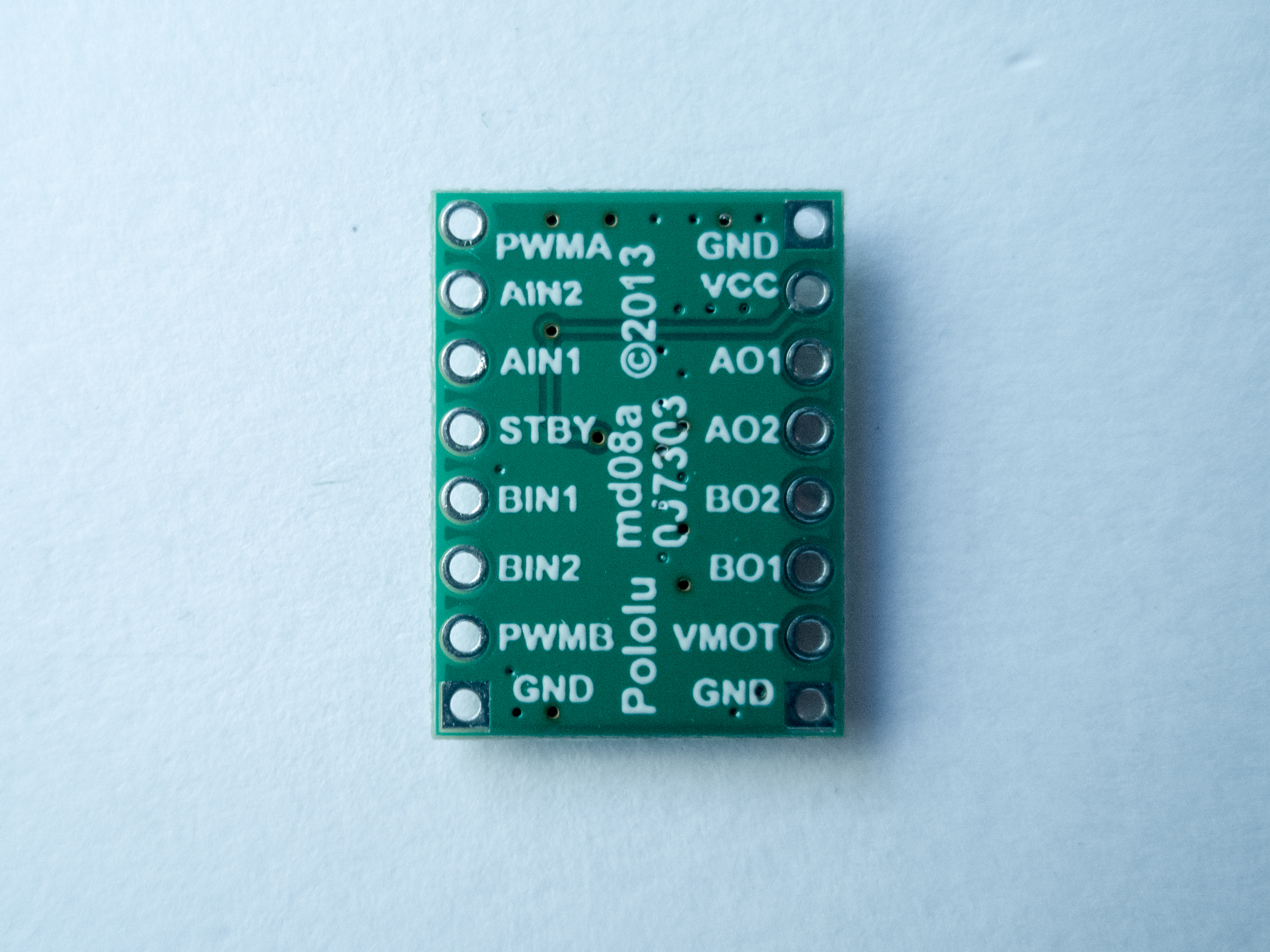
Figure 12 shows the Sparkfun board, and Figures 13 and 14 show the Pololu board front and back. The Pololu board is labeled on the back. You can see that both boards have the same pins, even though the layouts are different. Click on any of the images to see them larger.
You can change the direction and speed of the motor using the motor driver. The truth table below shows how the motor driver works.
| AI1 | AI2 | PWMA | B1 | B2 | PWMB | Coil 1 | Coil 2 | |||
|---|---|---|---|---|---|---|---|---|---|---|
| H | L | H | – | – | L | Direction 1 | Off | |||
| L | H | H | – | – | L | Direction 2 | Off | |||
| L | L | – | – | – | L | Off | Off | |||
| H | H | – | – | – | L | Off | Off | |||
| – | – | L | H | L | H | Off | Direction 1 | |||
| – | – | L | L | H | H | Off | Direction 2 | |||
| – | – | L | H | H | H | Off | Off | |||
| – | – | L | L | L | H | Off | Off |
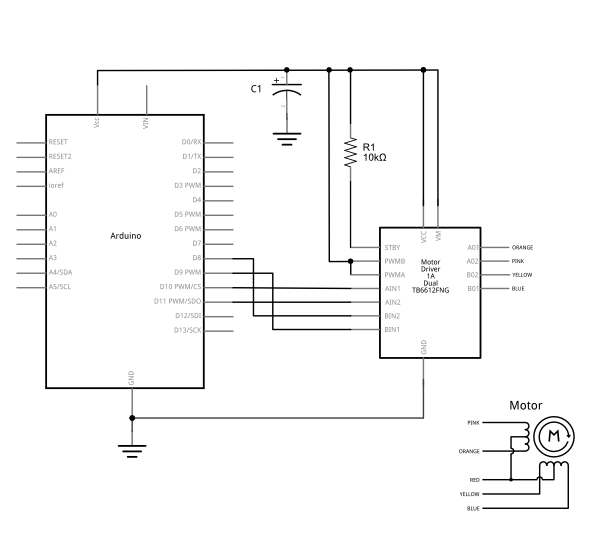
For this lab, the PWMA and PWMB pins connect to Vcc so that the driver circuits stay fully energized. The motor logic pins are also connected to designated digital pins on your Arduino so you can set them HIGH and LOW to turn the motor in one direction, or LOW and HIGH to turn it in the other direction. The motor supply voltage connects to the voltage source for the motor, which is usually an external power supply.
Connect the H-bridge and Motor
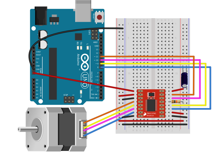
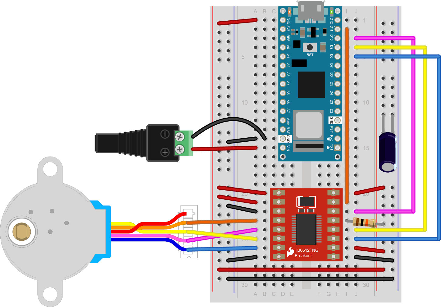
This motor nominally runs on 5 volts. It will run as low as 3.3 volts if you give it enough current (about 110 mA). It can run on the current supplied to an Uno or Nano 33 IoT’s USB connection. Ideally, though, you should run it from an external power supply, as described later in the lab. Table 2 below details the pin connections in the circuit. Figures 15 through 17 show how to connect the circuit.
| Motor Driver Physical pin number | Pin function | Circuit Connection |
|---|---|---|
| 1 | VMOT, motor power | Arduino Vcc if using USB power. Arduino Vin if using an external power supply. |
| 2 | Vcc | 5V (Uno) or 3.3V (Nano 33 IoT) |
| 3 | Ground | Ground |
| 4 | AOUT1 | motor coil 1 pin 1 |
| 5 | AOUT2 | motor coil 1 pin 2 |
| 6 | BOUT2 | motor coil 2 pin 1 |
| 7 | BOUT1 | motor coil 2 pin 2 |
| 8 | Ground | Ground |
| 9 | Ground | Ground |
| 10 | PWMB | 5V (Uno) or 3.3V (Nano 33 IoT) |
| 11 | BIN2 | Arduino digital pin 8 |
| 12 | BIN1 | Arduino digital pin 9 |
| 13 | Standby | 10-kilohm resistor to 5V (Uno) or 3.3V (Nano 33 IoT) |
| 14 | AIN1 | Arduino digital pin 10 |
| 15 | AIN2 | Arduino digital pin 11 |
| 16 | PWMA | 5V (Uno) or 3.3V (Nano 33 IoT) |
Made with Fritzing
Once you have the motor and the driver connected, you’re ready to program the microcontroller.
Program the microcontroller
The Arduino Stepper library is written to work with H-bridge and transistor array stepper motor drivers. You initialize the library by telling it how many steps per revolution your motor turns, and what the pin numbers are that are controlling the coils, as follows:
Stepper myStepper(stepsPerRevolution, coil1Pin1, coil1Pin2, coil2Pin1, coil2Pin2);
After that, you move it one direction or the other by calling myStepper.step(steps); If you step it a positive number, it moves one direction; a negative number moves it the opposite direction.
You can install the Stepper library using the Library Manager of the Arduino IDE, if it’s not already installed. Once you’ve done so, there will be examples for it available in the File -> Examples menu.
Regardless of what motor driver you are using, the first thing you should do after wiring up a stepper motor is to write two test programs, one to test if it’s stepping, and one to test if it can rotate one revolution in both directions. The Arduino Stepper library includes these two programs as examples.
The first example to start with is the stepper_oneStepAtATime example. For your first program, it’s a good idea to run the stepper one step at a time, to see that all the wires are connected correctly. If they are, the stepper will step one step forward at a time, every half second, using the code below. Make sure to change the number of steps per revolution and pin numbers if needed, to match your stepper. The number of steps per revolution will depend on your individual stepper, so check the data sheet for the number of steps per revolution:
#include "Stepper.h"

const int stepsPerRevolution = 512;

// initialize the stepper library on pins 8 through 11:
Stepper myStepper(stepsPerRevolution, 8,9,10,11);

int stepCount = 0;       // number of steps the motor has taken

void setup() {
  // initialize the serial port:
  Serial.begin(9600);
}

void loop() {
  // step one step:
  myStepper.step(1);
  Serial.print("steps:" );
  Serial.println(stepCount);
  stepCount++;
  delay(500);
}
If your circuit is connected correctly, the stepper will step one step forward at a time, every half second.
Once you’ve got that working, try making the stepper move one whole revolution at a time using the stepper_oneRevolution example:
#include "Stepper.h"

const int stepsPerRevolution = 512;

// initialize the stepper library on pins 8 through 11:
Stepper myStepper(stepsPerRevolution, 8,9,10,11);

void setup() {
  // set the speed at 60 rpm:
  myStepper.setSpeed(10);
  // initialize the serial port:
  Serial.begin(9600);
}

void loop() {
  // step one revolution  in one direction:
   Serial.println("clockwise");
  myStepper.step(stepsPerRevolution);
  delay(500);

   // step one revolution in the other direction:
  Serial.println("counterclockwise");
  myStepper.step(-stepsPerRevolution);
  delay(500);
}
When you run this code, you should see the motor turn one revolution, wait half a second, then turn one revolution in the other direction.
With a high-step-count stepper, you may want to change the speed using myStepper.setSpeed(). If the motor steps are run too fast, the motor coils don’t have a chance to energize and de-energize in order to step the motor. You don’t have to use the speed command; you can control the speed in your own code by changing the delay between steps and the number of steps you take per step() command.
My motor’s only going one direction!
If you find that the motor only turns in one direction, you probably have the pin connections wrong. It could be that you got the order wrong. Try rearranging the order of the pins. Disconnect power each time you try changing your connections. First, try swapping the two pins on each coil (e.g. blue and yellow, pink and orange) and run it again. If that fails, swap one wire from one coil for one wire from the other coil. Keep trying variations until your motor goes around in one direction, then goes around in the opposite direction.
Unipolar Stepper Control
The steps above showed you how to control a bipolar stepper, but the motor shown was actually a unipolar motor. Remember the red wire you didn’t connect? That wire connects the two coils and can act as a common power source or ground wire. To use the motor as a unipolar motor, try connecting that wire (wire 1) of the motor to the Vin power supply from the DC power jack. You should see that there’s not a lot of difference.
Attach something to the stepper
If you want to mount an arm or pointer to the stepper motor, you need to make a hole for the pointer that fits the shaft perfectly. You could measure this with a caliper. There are also collars and shaft couplers that you can buy for various stepper motors that will allow you to attach things to your stepper. ServoCity has a number of examples, as does Pololu. To pick a good shaft adapter, you need to know what you’re going to do with the stepper, and what the size and shape of the shaft is.
Using an External Power Supply
Although the examples shown above used a motor that can run on the voltage and current supplied to the Arduino via USB, this is not the norm for stepper motors. Most of the time you need to use an external power supply. You should match your supply to your motor. Keep in mind that if you have, say, a 12-Volt power supply and a 5-volt motor, you can add a 5-volt voltage regulator, as shown in the breadboard lab. Figures 18 through 20 show a few different options for powering different stepper motors.
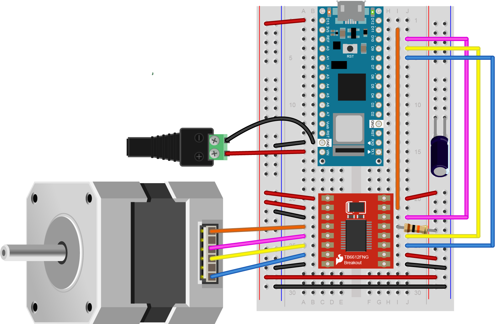
Figures 18 and 19 show how you might power a 9V stepper motor from an Uno or Nano, respectively. Figures 18 and 19 show a NEMA-17 stepper motor. Figure 20 shows how you could power a 5V stepper from a Nano, using a 9-12V DC power supply for the Nano and a 5V voltage regulator for the motor and motor driver.
It’s worth noting that when the Nano 33 IoT is powered from its Vin pin, the USB connection no longer powers the Nano. Instead, the Vin powers the Nano. You can still get 3.3V from the 3.3V out pin (pin 2), however.
The exact voltage and amperage requirements for a stepper motor circuit will depend on the motor you are using. These images show a few options that can work, but you should adapt them depending on the particular electrical characteristics of your motor.
Applications
Stepper motors have lots of applications. One of the most common is to make a tw0- or three-axis gantry for CNC plotters, printers, and mills. A gantry is a structure on which you mount motors and the equipment that they are moving in order to achieve a task. Evil Mad Science’s AxiDraw is a good two-axis example. You can also use steppers to create animation in art projects, as seen in Nuntinee Tansrisakul’s Shadow through Time. Heidi Neilson’s Moon Arrow is another example that uses stepper motors and geolocation tools to make an arrow that always points at the moon.