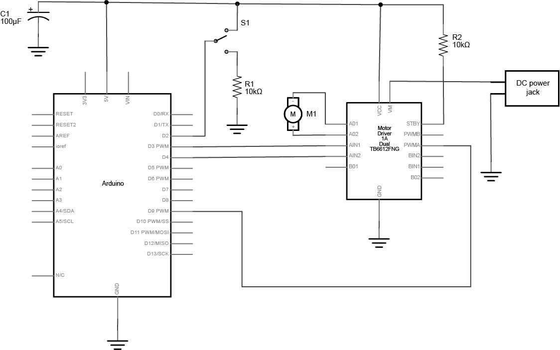
Schematic diagram of an Arduino connected to a motor driver to control a DC motor. The Arduino and switch are connected as described in the drawing above. A motor driver has been added, and is connected to as follows: PWMA is connected to the Arduino’s digital pin 9. AIN1 is connected to digital pin 4. AIN2 is connected to digital pin 3 on the Arduino. AO1 and AO2 are connected to the DC motor’s two connections. The ground pins are connected to ground. VM is connected to the positive terminal of a DC power source for the motor. The power source’s negative terminal is connected to ground. The motor driver’s Vcc pin is connected to the Arduino’s voltage output (5V or 3.3V depending on your model). The Standby pin is connected to voltage through a 10-kilohm resistor. The rest of the H-bridge pins are unconnected.