The Arduino Nano R4 is 5-volt microcontroller board in a Nano format. It can do the things that the Arduino Uno can, and it has a number of additional features for physical computing projects. This page introduces some of the functions that this board supports.
Feature Overview
The Nano R4 has a number of useful features, including:
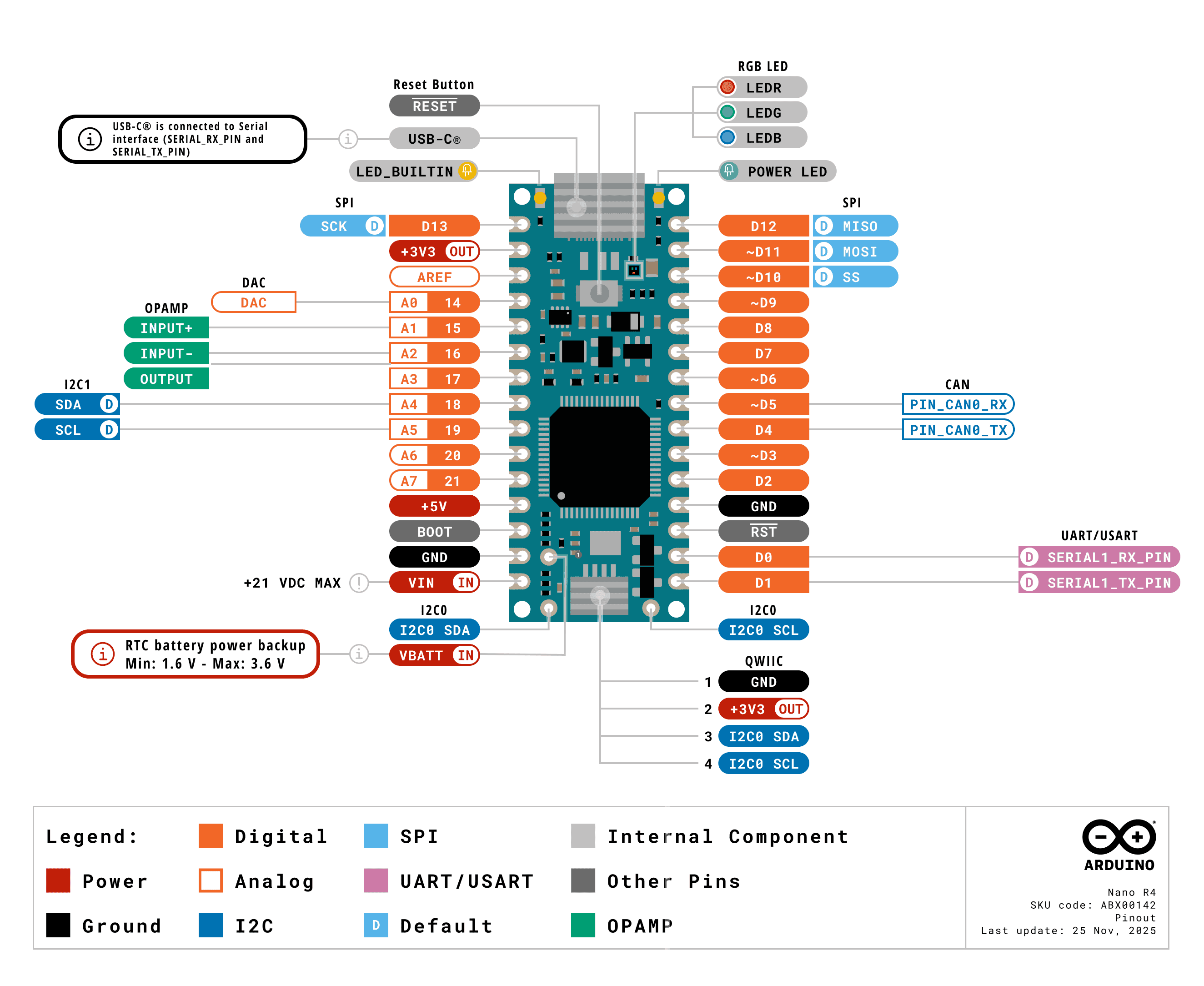
The Nano R4 is based on the original Arduino Nano pin layout. It’s a dual-inline package (DIP) format, meaning it’s got two rows of pins spaced 0.1 inches apart, so it fits nicely on a solderless breadboard. You can get it with or without header pins, and it’s small enough that you can incorporate it in handheld projects as well.
The physical pin numbering for DIP devices goes in a U shape. Holding the micro USB connector at the top, the numbering starts with physical pin 1 on the upper left, counting down the left side to pin 14 on the lower left, then counting from pin 15 on the lower right, to pin 28 on the upper right. For the most part, the left side of the board is power and analog inputs, and the right side is digital I/O pins.
The Nano boards all follow a similar pin layout, as follows, counting from physical pin 1 (upper left) to pin 15 (lower left) across to pin 16 (lower right) to pin 30 (upper right). Figure 1 shows the pin diagram.
Pin 1: Digital I/O 13
Pin 2: 3.3V output
Pin 3: Analog Reference
Pin 4-11: Analog in A0-A7; Digital I/O 14-21 Pin 12: +5V
The full specifications of the Nano R4 and an official pin diagram can be found on its User Manual page.
Typical Breadboard Layout
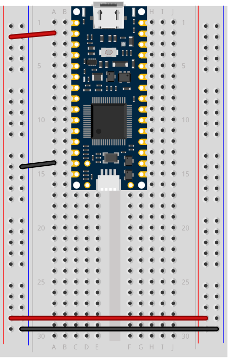
Figure 2. Breadboard view of an Arduino Nano R4 connected to a breadboard.
In a typical breadboard layout for the Nano R4, The +3.3 volts and ground pins of the Nano are connected by red and black wires, respectively, to the left side rows of the breadboard. +3.3 volts is connected to the left outer side row (the voltage bus) and ground is connected to the left inner side row (the ground bus). The side rows on the left are connected to the side rows on the right using red and black wires, respectively, creating a voltage bus and a ground bus on both sides of the board. If you are making a 5-volt circuit instead of a 3.3-volt circuit, you can use the +5 volt pin (pin 12) instead of the +3.3 volt pin.
Like many microcontrollers these days, the Nano R4 uses a USB-C connector. This is a delicate connector, and you shouldn’t handle the board by the connector. If you are mounting the board in a project box or as a wearable and you are using the USB connection, make sure the cable and the board are mounted so that they won’t move relative to each other.
I2C and the Qwiic Connector
The Nano R4 has two I2C buses. The first I2C bus on pins A4 and A5 operates at +5V, like the Nano R4 itself. This bus can be connected to using the Wire library, as usual. The second I2C bus is connected to the qwiic connector, and operates on +3.3V.
The Qwiic connector, the small rectangular part at the bottom center, gives you an easy way to connect I2C peripherals to your board using Qwiic or Qwiic-compatible connectors. Sparkfun’s Qwiic sensors, Adafruit’s Stemma sensors, and Arduino’s Modulino sensors are all compatible. For more on these, see this section of the I2C introduction. For an example, see this lab on the Sparkfun Qwiic Shield for Nano.
Processor
The Nano 33 IoT has a Renesas R7FA4M1AB3CFM 32-bit processor. It’s considerably faster than the Uno’s processor (48MHz clock speed compared to the Uno’s 16MHz, and a 32-bit processor compared to the Uno’s 8-bit processor) and has more memory (256 kB flash, 32 kB SRAM and 8 kB data memory (EEPROM) compared to the Uno’s 2KB/32KB). That makes for more programming space at a faster speed.
Input and Output (GPIO) Pins
The Nano R4 has 14 digital I/O pins and 8 analog input pins. The analog in pins can also be used for digital in and out, for a total of 22 digital I/O pins. Of those, 6 can be used for PWM out (pseudo-analog out): digital pins 3, 5, 6, 9, 10, and 11. One pin A0, can also be used as a true analog out, because it has a digital-to-analog converter (DAC) attached (here’s an example of how to use it). There are also more hardware interrupt pins than the Uno; pins 0,1,2,3,8,8,12,13, and A1 through A6 can be used as hardware interrupts. Hardware interrupts make it possible to read very fast changes in digital input and output. For example, rotary encoders work best when attached to interrupt pins.
Serial and USB
The Nano 33 IoT is USB-native. That means it can operate as a few different USB devices: asynchronous serial, keyboard or mouse (also known as Human Interface Device, or HID). This is different than the Uno, which has a dedicated USB-to-serial chip on the board, but can only operate as a USB serial device.
There’s also a second asynchronous serial port on pins 0 and 1 that you can use for connecting to other serial devices while still connecting to your personal compuuter. The serial port on pins 0 and 1 is called Serial1, so you’d type Serial1.begin(9600) to initialize it, for example.
Real-Time Clock
The Nano R4 also has a real-time clock module built into the processor, which is accessible using the RTC library that also works on the Uno R4. With this, you can keep track of hours, minutes and seconds much easier. As long as the board is powered, the realtime clock will keep time. Like all libraries, it comes with examples when you install it.
Scheduler
The Nano 33 IoT can run multiple loops at once, using the Scheduler library. When you’ve got an application that needs two or more independent loop functions, this can be a quick way to do it.
Uploading to the Nano R4
If you’ve used an Uno before, and are migrating to the Nano R4 board, you may notice that the serial connection behaves differently. When you reset the MKR, Nano, or Leonardo boards, or upload code to them, the serial port seems to disappear and re-appear. The newer boards can communicate natively using USB, unlike the Uno R3. They don’t need a separate USB-to-serial chip. Because of this, they can be programmed to operate as a mouse, or as a keyboard. Since they are USB-native, their USB connection gets reset when you upload new code or reset the processor. That’s normal behavior for them; it’s as if you turned off the device, then turned it back on. Once it’s reset, it will let your computer’s operating system know that it’s ready for action, and your serial port will reappear. This takes a few seconds. It means you can’t reset the board and then open the serial port in the next second. You have to wait those few seconds until the Arduino board has made itself visible to the computer’s operating system again.
If you’re doing keyboard or mouse, the serial port number will also change when you add those functions. You’ll still be able to send and receive serial data as usual, but you’ll have to re-choose the port in the Boards -> Port submenu after you program your Nano to be a HID device.
If you have trouble getting the Nano R4 to appear in the Arduino IDE, double-tap the reset button at the top center of the board. This will put the board into bootloader mode, meaning that it will show up as a serial device, but not start running the sketch yet. This mode also makes it easier to recover your board if you write a sketch you can’t control, such as a runaway mouse sketch.
In this lab, you’ll build an alternative computer mouse using an Arduino Leonardo using a joystick to move the mouse left, right, up and down. You’ll use the joystick’s select button to replace the mouse button as well.
Introduction
In this lab, you’ll build an alternative computer mouse using an Arduino Leonardo using a joystick to move the mouse left, right, up and down. You’ll use the joystick’s select button to replace the mouse button as well. You’ll see how to scale the analog outputs of the joystick to a reasonable range using the map() function.
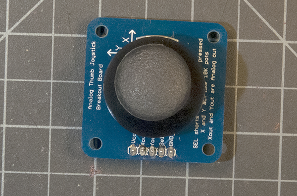
A joystick is typically made up of two potentiometers, one for the X axis and one for the Y axis. The potentiometers are mounted so that when the joystick is at rest in the center, the potentiometers are at the middle of their range. Some joysticks like the Thumb Joystick used here also have a pushbutton that you can press by pushing down on the stick. (Note: SparkFun and Parallax have equivalent models as well.)
What You’ll Need to Know
To get the most out of this lab, you should be familiar with the following concepts. You can check how to do so in the links below:
Figures 1-6 show the parts you’ll need for this exercise. Click on any image for a larger view.
Figure 1. A solderless breadboard.
Figure 2. Arduino Nano 33 IoT
Figure 3. 22AWG solid core hookup wires.
Figure 4. Resistors. Shown here are 220-ohm resistors. For this exercise, you’ll need 10-kilohm resistors (10K resistors are brown-black-orange. For more, see this resistor color calculator)
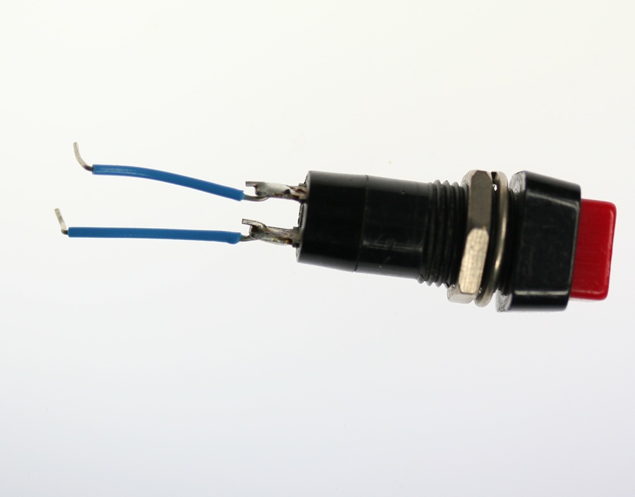
Figure 5. A pushbutton with two wires soldered one to each of the button’s contacts. Any switch will do the job as well.
Figure 6. A breadboard-mountable joystick
Click on any image for a larger view
About mouse control
NOTE: The sketches contained in this lab will cause the Arduino Leonardo to take control of your mouse. Make sure they’re working properly before you add the mouse commands. The example doesn’t introduce the mouse commands until the end of the lab. Instead, messages are printed to the serial monitor to tell you what should happen. When you’ve run this and seen the serial messages occurring when you think they should, then you can add the mouse commands safely.
The sketches here will work on an Uno until you add the mouse commands. So you can test this on an Uno simply by commenting out any line that says Mouse.begin() or Mouse.move().
Note on Mouse, Keyboard, and Serial Ports
The Mouse and Keyboard libraries on the SAMD boards (MKRZero, MKR1xxx, Nano 33IoT) have an unusual behavior: using them changes the serial port enumeration. When you include the Keyboard library in a sketch, your board’s serial port number will change. For example, on MacOS, if the port number is /dev/cu.usbmodem14101, then adding the Keyboard library will change it to /dev/cu.usbmodem14102. Removing the Keyboard library will change it back to /dev/cu.usbmodem14101. Similarly, if you double-tap the reset button to put the board in bootloader mode, the serial port will re-enumerate to its original number.
Windows and HID Devices
You may have trouble getting these sketches to work on Windows. On Windows, the default Arduino drivers must be uninstalled so the system can recognize the Arduino as both serial device and HID device. Read this issue and follow the instructions there.
Recovering From a Runaway HID (Mouse or Keyboard) Sketch
Programs which control your keyboard and mouse can make development difficult or impossible if you make a mistake in your code. If you create a mouse or keyboard example that doesn’t do what you want it to, and you need to reprogram your microcontroller to stop the program, do this:
Open a new blank sketch.
This sketch is your recovery:
void setup() {

}
void loop() {

}
Programming the board with this blank sketch removes your mistaken sketch and gives you control again. To do this, however, you need the current sketch to stop running. So:
Put the microcontroller in bootloader mode and upload the blank sketch
On the SAMD boards, you can do this by double-tapping the reset button. The on-board LED will begin glowing, and the bootloader will start so that you get a serial port enumeration, but the sketch won’t run. On the Leonardo and other 32U4-based boards, hold the reset down until you’ve given the upload command. The 32U4 bootloader will take a few seconds before it starts the sketch, so the uploader can take command and load your blank sketch.
Once you’ve got the blank sketch on the board, review the logic of your mistaken Keyboard or Mouse sketch and find the problem before uploading again.
Prepare the breadboard
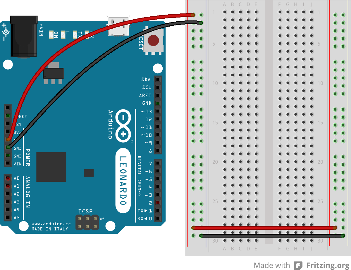
Connect power and ground on the breadboard to power and ground from the microcontroller. On the Arduino module, use the 5V and any of the ground connections as shown below in Figure 7:
Figure 7. An Arduino Leonardo on the left connected to a solderless breadboard, right.
Figure 8. Breadboard view of Arduino Nano mounted on a breadboard.
Figure 8. Breadboard view of an Arduino Nano connected to a breadboard. The +3.3 volts and ground pins of the Arduino are connected by red and black wires, respectively, to the left side rows of the breadboard. +3.3 volts is connected to the left outer side row (the voltage bus) and ground is connected to the left inner side row (the ground bus). The side rows on the left are connected to the side rows on the right using red and black wires, respectively, creating a voltage bus and a ground bus on both sides of the board.
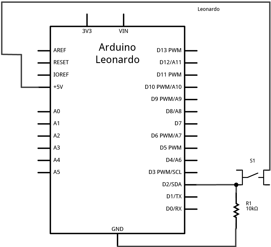
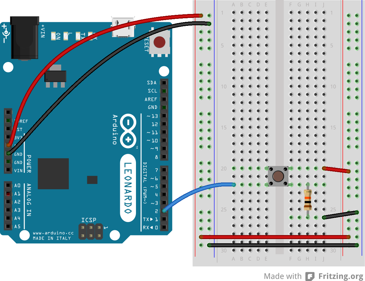
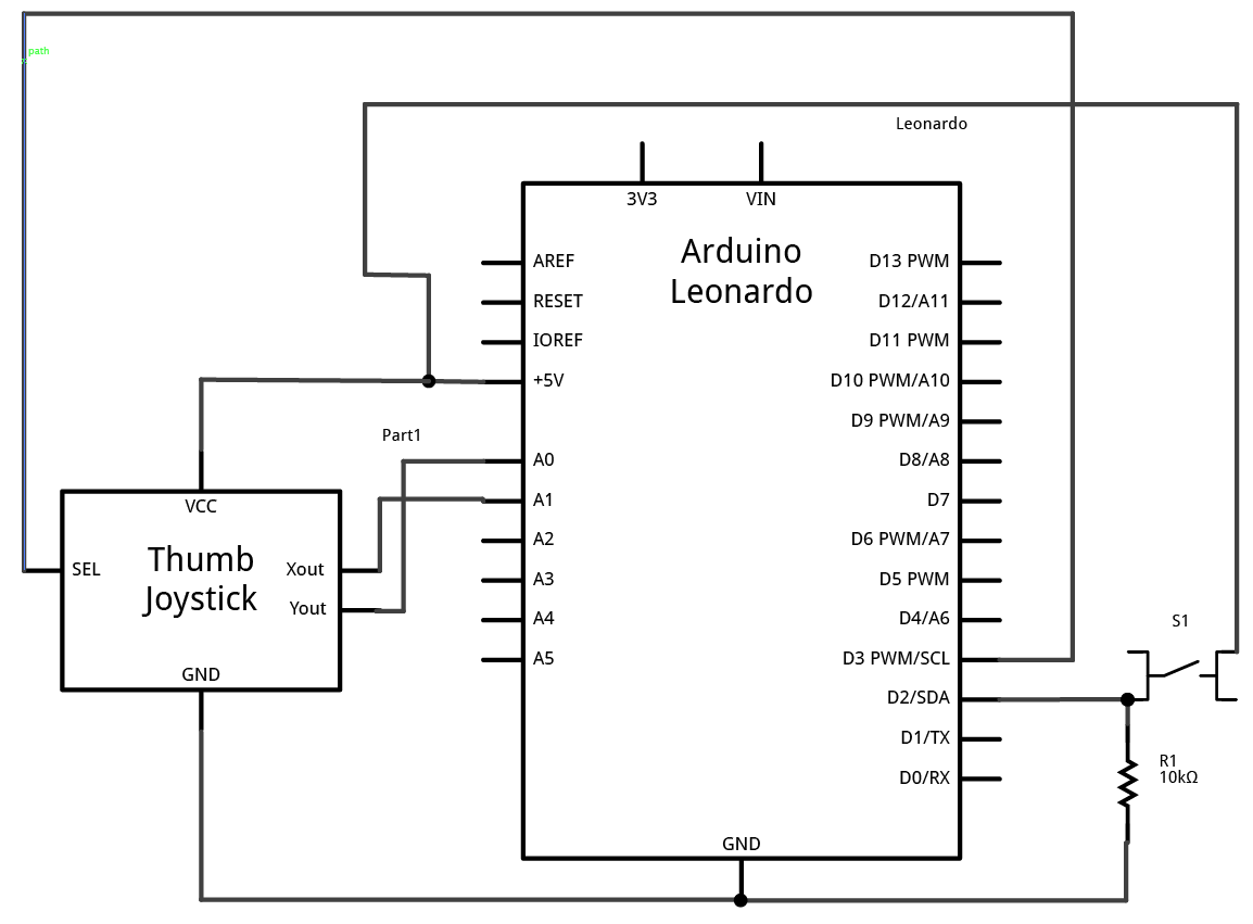
Attach a pushbutton to digital pin 2 as shown below in Figure 10. For Arduino Nano view, see Figure 11. For the schematic view, see Figure 9. Connect one side of the pushbutton to 5 volts, and the other side of the pushbutton to a 10-kilohm resistor. Connect the other end of the resistor to ground. Connect the junction where the pushbutton and the resistor meet to digital pin 2. (For more on this digital input circuit, see the Digital Input Lab).
Figure 9. Schematic view of an Arduino Leonardo connected to a pushbutton.
Figure 10. Breadboard view of an Arduino Leonardo connected to a pushbutton.
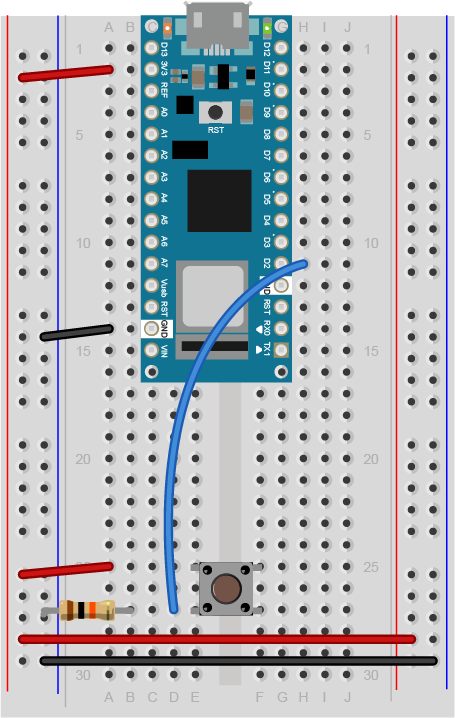
Figure 11. Breadboard view of an Arduino Nano connected to a pushbutton.
Figure 11. Breadboard view of an Arduino Nano connected to a pushbutton. The +3.3 volts and ground pins of the Arduino are connected by red and black wires, respectively, to the left side rows of the breadboard. +3.3 volts is connected to the left outer side row (the voltage bus) and ground is connected to the left inner side row (the ground bus). The side rows on the left are connected to the side rows on the right using red and black wires, respectively, creating a voltage bus and a ground bus on both sides of the board. The pushbutton is mounted across the middle divide of the solderless breadboard. A 10-kilohm resistor connects from the same row as pushbutton’s bottom left pin to the ground bus on the breadboard. There is a wire connecting to digital pin 2 from the same row that connects the resistor and the pushbutton. The top left pin of the pushbutton is connected to +3.3V.
Add a thumb joystick
Add a thumb joystick, as shown below in Figure 13. For the Arduino Nano view, see Figure 14. For the schematic view, see Figure 11. Attach the X out to analog input 0, the Y out to analog input 1, and the select button to digital input 3.
Figure 12. Schematic view of a pushbutton and a joystick attached to an Arduino Leonardo
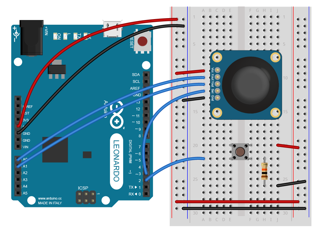
Figure 13. Breadboard view of an Arduino Leonardo connected to a pushbutton and a joystick.
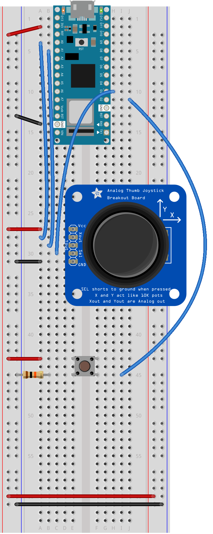
Figure 14. Breadboard drawing of an Arduino Nano connected to a pushbutton and a joystick.
Program the module to read the pushbutton
Follow the same steps as you did in the first Mouse Control lab to read when the pushbutton on pin 2 is pressed. Your code should only print out a message when the button changes state. Similarly, set up a global variable to track whether or not you’re controlling the mouse, called mouseIsActive. Each time the pushbutton on pin 2 is pressed, change the state of this variable from false to true, just like you did in the first mouse control lab.
// Global variables:
int lastButtonState = LOW;            // state of the button last time you checked
boolean mouseIsActive = false;    // whether or not the Arduino is controlling the mouse

void setup() {
  // initialize serial communication:
  Serial.begin(9600);
  pinMode(2, INPUT);
}

void loop() {
  // read the first pushbutton:
  int buttonState = digitalRead(2);

  // if it's changed and it's high, toggle the mouse state:
  if (buttonState != lastButtonState) {
    if (buttonState == HIGH) {
      // if mouseIsActive is true, make it false;
      // if it's false, make it true:
      mouseIsActive = !mouseIsActive;
      Serial.print("Mouse control state: ");
      Serial.println(mouseIsActive);
    }
  }
  // save button state for next comparison:
  lastButtonState = buttonState;
}
Program the Leonardo to read the Joystick
Add code to the main loop to read the joystick X and Y outputs and print them.
// Global variables:
int lastButtonState = LOW;            // state of the button last time you checked
boolean mouseIsActive = false;    // whether or not the Arduino is controlling the mouse

void setup() {
  // initialize serial communication:
  Serial.begin(9600);
  pinMode(2, INPUT);
}

void loop() {
  // read the first pushbutton:
  int buttonState = digitalRead(2);

  // if it's changed and it's high, toggle the mouse state:
  if (buttonState != lastButtonState) {
    if (buttonState == HIGH) {
      // if mouseIsActive is true, make it false;
      // if it's false, make it true:
      mouseIsActive = !mouseIsActive;
      Serial.print("Mouse control state: ");
      Serial.println(mouseIsActive);
    }
  }
  // save button state for next comparison:
  lastButtonState = buttonState;

  // read the analog sensors:
  int sensor1 = analogRead(A0);
  delay(1);
  int sensor2 = analogRead(A1);
  // print their values. Remove this when you have things working:
  Serial.print(sensor1);
  Serial.print("  ");
  Serial.println(sensor2);
}
Map the X and Y output readings
The Mouse.move() command has three parameters: the horizontal movement, the vertical movement, and the scroll wheel movement. All movements are relative, so Mouse.move(1,0,0); moves one pixel to the right; Mouse.move(-1,0,0); moves one pixel to the left; Mouse.move(0,1,0); moves one pixel down; and Mouse.move(0,-1,0); moves one pixel up. Moving the mouse more than about 5 pixels in any direction is a very fast move. So the ideal range for the joystick is if it can move the cursor 5 pixels in any direction.
In order to do this, you need to scale the X and Y outputs from the default range that they return (0 to 1023) to a range from -5 to 5. You can do this using the map() function. Map takes five parameters: the input value, the range of the input value, and the desired output range, like so:
result = map(inputValue, inputMinimum, inputMaximum, outputMinimum, outputMaximum);
So, if your input range is 0 to 1023, and your output range is -5 to 5, you might map like this:
result = map(sensorReading, 0, 1023, -5, 5);
Add code to the main loop to map the X and Y outputs to a range from -5 to 5. Print the mapped values instead of the original sensor values.
// read the analog sensors:
  int sensor1 = analogRead(A0);
  delay(1);
  int sensor2 = analogRead(A1);

  int xAxis = map(sensor1, 0, 1023, -5, 5);
  int yAxis = map(sensor2, 0, 1023, -5, 5);

 // print their values. Remove this when you have things working:
  Serial.print(xAxis);
  Serial.print("  ");
  Serial.println(yAxis);
NOTE: If your joystick defaults to -1 at rest on one axis or both, try adding 1 to the result of the map command. Try different output ranges and see what they do.
When you run this sketch, you should see the Mouse Control State message once every time you press the first pushbutton, and the values of the X and Y axes of the joystick, mapped to a range of -5 to 5. You still need to add in the select button on the joystick, however.
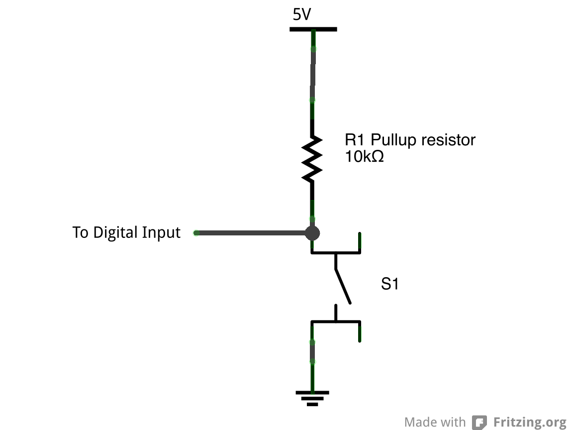
It is, in fact, wired to connect to ground when you press it. To read it, then, you’d still use digitalWrite(), but you’d expect it to go low when pressed instead of high. And instead of a pulldown resistor like you’ve used in those other two labs, you’d use a pullup resistor, so that it’s connected to 5V when the switch is not open.
You can see the schematic for a pullup resistor circuit below in Figure 12.
Figure 15: Schematic view of a pushbutton and a pullup resistor.
The Arduino has built-in pullup resistors that you can use on the digital inputs. Most microcontrollers have these. When you set the pin to be an input using the pinMode() command, use the parameter INPUT_PULLUP instead of INPUT. This will activate the built-in pullup resistor on that pin, so you only have to attach a switch between the pin and ground.
The advantage of connecting your pushbutton to ground instead of 5V is that you can use the internal pullup resistor instead of having to add an external resistor. The disadvantage is that your switch logic is inverted: HIGH means the switch is open, and LOW means it is closed. Most of the time you can wire your switches either way, but when you have a switch that’s already wired to ground like the select button in the joystick, you have to use the internal pullups and inverted logic.
Previously, you wired the select button to digital input 3. To read the select button in this sketch, add a pinMode command to the setup that makes it an INPUT_PULLUP. Then in the main loop, check if the mosueIsActive variable is true. If it is, then use digitalRead() to read the select button and store it in a local variable called button2State.
Add the following at the end of the setup command:
 // make pin 3 an input, using the built-in pullup resistor:
  pinMode(3, INPUT_PULLUP);
Then at the end of the loop, add the following code:
 if (mouseIsActive == true) {
     // read the second pushbutton:
    int button2State = digitalRead(3);
 }
The select button’s behavior should be like the mouse control pushbutton’s behavior: you only want something to happen when it changes. When the select button changes from off to on, you want it to perform a mouse click. When it changes from on to off, you want it to perform a mouse release. So you need to check for when the select button changes, just like you do with the other pushbutton.
To check for the select button to change, set up a global variable called lastButton2State to save its previous state. Then set up an if statement in the main loop after you read it to see if the current state and the previous state are different. If they are different, add another if statement to see if the current state is HIGH or LOW. If it’s LOW, then print “Mouse press” (remember,its logic is inverted). If the current state is HIGH, then print “mouse press”.
This block of code will look a lot like the code you used for Mouse Control to track the state change of the pushbutton on pin 2.
Add the following line before the setup command:
int lastButton2State = LOW; // state of the other button last time you checked
Then inside the if statement that you added to check the mouseIsActive variable, add the following code (the if statement is shown here too):
if (mouseIsActive == true) {
    // read the second pushbutton:
    int button2State = digitalRead(3);

    // if it's changed and it's high, toggle the mouse state:
    if (button2State != lastButton2State) {
      if (button2State == LOW) {
        Serial.println("mouse pressed");
      }
      else {
        Serial.println("mouse released");
      }
    }
    // save second button state for next comparison:
    lastButton2State = button2State;
  }
When you run this code, you should see the words “mouse pressed” once when you press the select button, and “mouse released” when you release the select button. If it prints continually, you have an error.
When you’ve got that working, you’re ready to take control of the mouse.
Add commands to control the mouse
The Mouse.begin() command is called in the setup. It initializes mouse control from your Leonardo.
Include the Mouse library at the top of your sketch. Modify the setup by adding the command Mouse.begin(). Then, in the loop where check if mouseIsActive is true, add Mouse.move commands to move as needed. Also add Mouse.press() when the select button is pressed, and Mouse.release() when it is released.
Then in the main loop, add the following lines to the if statement that checks mouseIsActive:
 if (mouseIsActive == true) {
    Mouse.move(xAxis, yAxis, 0);

    // read the second pushbutton:
    int button2State = digitalRead(3);

    // if it's changed and it's high, toggle the mouse state:
    if (button2State != lastButton2State) {
      if (button2State == LOW) {
        Serial.println("mouse pressed");
        Mouse.press();
      }
      else {
        Serial.println("mouse released");
        Mouse.release();
      }
    }
That’s the whole sketch. When you run this, press the mouse control pushbutton, then move the joystick and press the select button. You should have full mouse control.
In this sketch, you can see the value of scaling an analog sensor’s readings to match the output range you need. Since the joystick potentiometers are at rest in the middle of their range, scaling them from -5 to 5 gives you easy control of the mouse movement, which is relative. You can also see how reading the state change of a digital input is important. You’re doing it for two different buttons in this sketch.
In this lab, you’ll build an alternative computer mouse using an Arduino Leonardo using pushbuttons to move the mouse left, right, up and down. You’ll see the difference between reading a digital input continually and reading for a change of state.
Introduction
In this lab, you’ll build an alternative computer mouse using an Arduino Leonardo using pushbuttons to move the mouse left, right, up and down. You’ll see the difference between reading a digital input continually and reading for a change of state.
What You’ll Need to Know
To get the most out of this lab, you should be familiar with the following concepts. You can check how to do so in the links below:
Figures 1-5 show the parts you’ll need for this exercise. Click on any image for a larger view.
Figure 1. A solderless breadboard.
Figure 2. Arduino Nano 33 IoT
Figure 3. 22AWG solid core hookup wires.
Figure 4. Resistors. Shown here are 220-ohm resistors. For this exercise, you’ll need 10-kilohm resistors (10K resistors are brown-black-orange. For more, see this resistor color calculator)
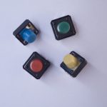
Figure 5. Pushbuttons. You’ll need 5 switches for this exercise. Any switches will do the job as well.
About mouse control
NOTE: The sketches contained in this lab will cause the Arduino Leonardo to take control of your mouse. Make sure they’re working properly before you add the mouse commands. The example doesn’t introduce the mouse commands until the end of the lab. Instead, messages are printed to the serial monitor to tell you what should happen. When you’ve run this and seen the serial messages occurring when you think they should, then you can add the mouse commands safely.
The sketches here will work on an Uno until you add the mouse commands. So you can test this on an Uno simply by commenting out any line that says Mouse.begin() or Mouse.move().
Note on Mouse, Keyboard, and Serial Ports
The Mouse and Keyboard libraries on the SAMD boards (MKRZero, MKR1xxx, Nano 33IoT) have an unusual behavior: using them changes the serial port enumeration. When you include the Keyboard library in a sketch, your board’s serial port number will change. For example, on MacOS, if the port number is /dev/cu.usbmodem14101, then adding the Keyboard library will change it to /dev/cu.usbmodem14102. Removing the Keyboard library will change it back to /dev/cu.usbmodem14101. Similarly, if you double-tap the reset button to put the board in bootloader mode, the serial port will re-enumerate to its original number.
Windows and HID Devices
You may have trouble getting these sketches to work on Windows. On Windows, the default Arduino drivers must be uninstalled so the system can recognize the Arduino as both serial device and HID device. Read this issue and follow the instructions there.
Recovering From a Runaway HID (Mouse or Keyboard) Sketch
Programs which control your keyboard and mouse can make development difficult or impossible if you make a mistake in your code. If you create a mouse or keyboard example that doesn’t do what you want it to, and you need to reprogram your microcontroller to stop the program, do this:
Open a new blank sketch.
This sketch is your recovery:
void setup() {

}
void loop() {

}
Programming the board with this blank sketch removes your mistaken sketch and gives you control again. To do this, however, you need the current sketch to stop running. So:
Put the microcontroller in bootloader mode and upload the blank sketch
On the SAMD boards, you can do this by double-tapping the reset button. The on-board LED will begin glowing, and the bootloader will start so that you get a serial port enumeration, but the sketch won’t run. On the Leonardo and other 32U4-based boards, hold the reset down until you’ve given the upload command. The 32U4 bootloader will take a few seconds before it starts the sketch, so the uploader can take command and load your blank sketch.
Once you’ve got the blank sketch on the board, review the logic of your mistaken Keyboard or Mouse sketch and find the problem before uploading again.
Prepare the breadboard
Connect power and ground on the breadboard to power and ground from the microcontroller. On the Arduino module, use the 5V and any of the ground connections as shown below in Figure 6. If using the Arduino Nano connect the 3.3V and ground pins according to Figure 7.
Figure 6. An Arduino Leonardo on the left connected to a solderless breadboard, right.
Figure 7. Breadboard view of an Arduino Nano mounted on a breadboard.
Figure 7. Breadboard view of an Arduino Nano connected to a breadboard. The +3.3 volts and ground pins of the Arduino are connected by red and black wires, respectively, to the left side rows of the breadboard. +3.3 volts is connected to the left outer side row (the voltage bus) and ground is connected to the left inner side row (the ground bus). The side rows on the left are connected to the side rows on the right using red and black wires, respectively, creating a voltage bus and a ground bus on both sides of the board.
Attach a pushbutton to digital pin 2 as shown below in Figure 9. See Figure 10 for Arduino Nano. See Figure 8 for the schematic view. Connect one side of the pushbutton to 5 volts, and the other side of the pushbutton to a 10-kilohm resistor. Connect the other end of the resistor to ground. Connect the junction where the pushbutton and the resistor meet to digital pin 2. (For more on this digital input circuit, see the Digital Input Lab).
Figure 8. Schematic view of an Arduino Leonardo connected to a pushbutton.
Figure 9. Breadboard view of an Arduino Leonardo connected to a pushbutton.
Figure 10. Breadboard view of an Arduino Nano connected to a pushbutton.
Figure 10. Breadboard view of an Arduino Nano connected to a pushbutton. The +3.3 volts and ground pins of the Arduino are connected by red and black wires, respectively, to the left side rows of the breadboard. +3.3 volts is connected to the left outer side row (the voltage bus) and ground is connected to the left inner side row (the ground bus). The side rows on the left are connected to the side rows on the right using red and black wires, respectively, creating a voltage bus and a ground bus on both sides of the board. The pushbutton is mounted across the middle divide of the solderless breadboard. A 10-kilohm resistor connects from the same row as pushbutton’s bottom left pin to the ground bus on the breadboard. There is a wire connecting to digital pin 2 from the same row that connects the resistor and the pushbutton. The top left pin of the pushbutton is connected to +3.3V.
Add four more pushbuttons
Repeat the last step, connecting four more pushbuttons to pins 3 through 6 as shown below in Figure 12. See Figure 11 for the schematic view. See Figure 13 for Arduino Nano.
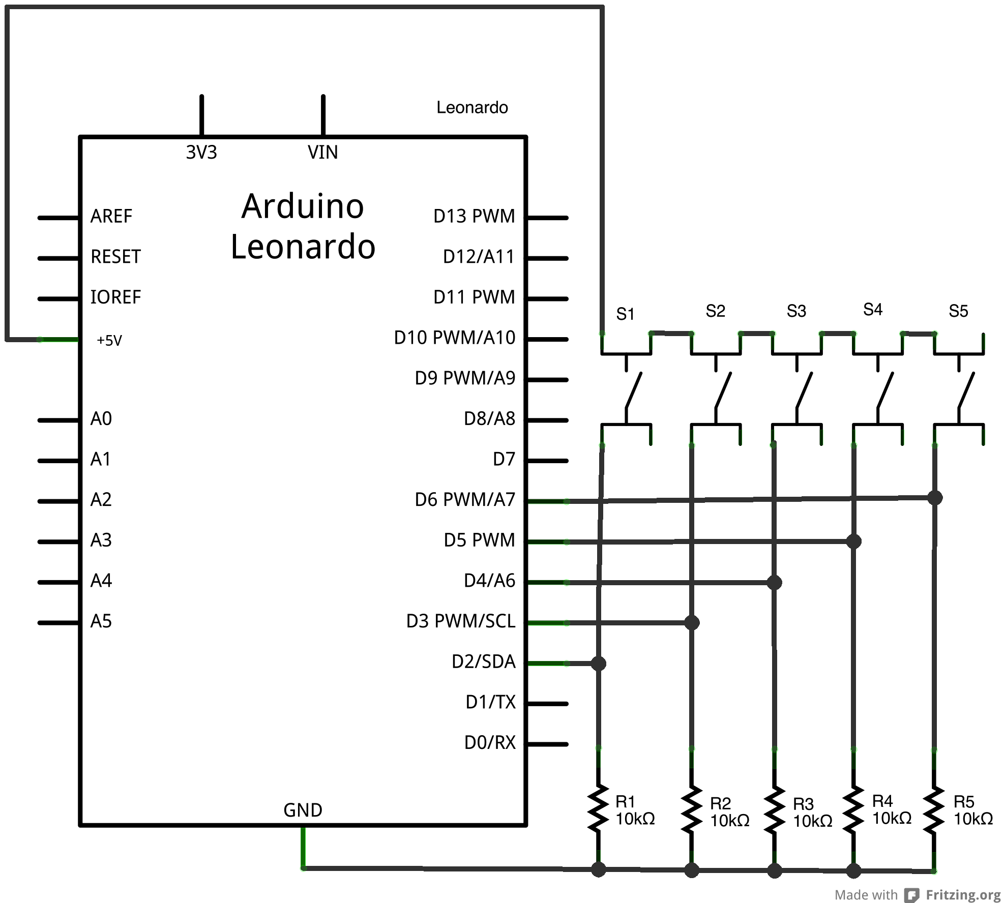
Figure 11. Schematic view of an Arduino Leonardo connected to five pushbutton.
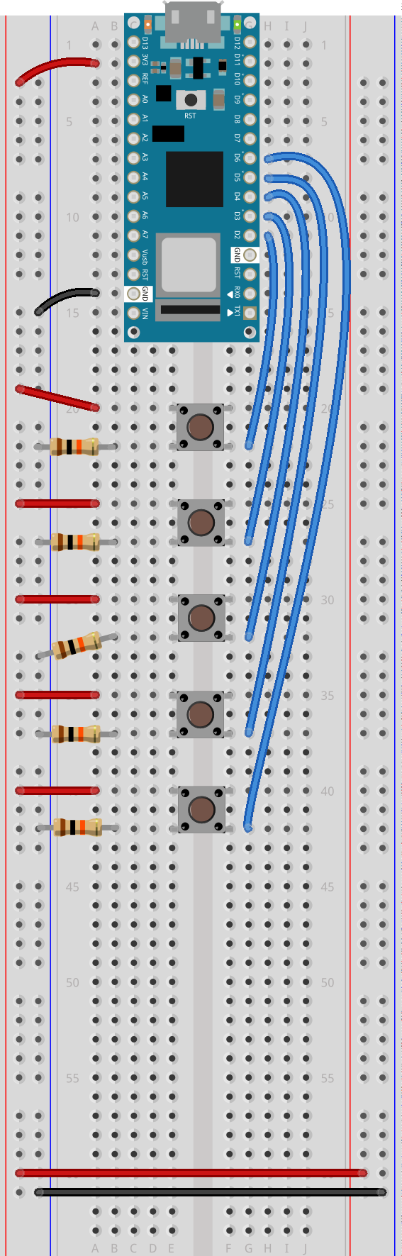
Figure 12. Breadboard view of an Arduino Leonardo connected to five pushbuttons.
Figure 13. Breadboard drawing of an Arduino Nano connected to five pushbuttons.
Figure 13. Breadboard drawing of an Arduino Nano connected to five pushbuttons at digital pins 2-6 respectively.
Program the module to read the pushbutton
Follow the same steps as you did in the first Mouse Control lab to read when the pushbutton on pin 2 is pressed. Your code should only print out a message when the button changes state.
Similarly, set up a global variable to track whether or not you’re controlling the mouse, called mouseIsActive. Each time the pushbutton on pin 2 is pressed, change the state of this variable from false to true, just like you did in the first mouse control lab.
// Global variables:
int lastButtonState = LOW;            // state of the button last time you checked
boolean mouseIsActive = false;    // whether or not the Arduino is controlling the mouse

void setup() {
  // initialize serial communication:
  Serial.begin(9600);
  pinMode(2, INPUT);
}

void loop() {
  // read the first pushbutton:
  int buttonState = digitalRead(2);

  // if it's changed and it's high, toggle the mouse state:
  if (buttonState != lastButtonState) {
    if (buttonState == HIGH) {
      // if mouseIsActive is true, make it false;
      // if it's false, make it true:
      mouseIsActive = !mouseIsActive;
      Serial.print("Mouse control state: ");
      Serial.println(mouseIsActive);
    }
  }
  // save button state for next comparison:
  lastButtonState = buttonState;
}
Activate the other four buttons
The other four pushbuttons are intended to control the mouse movement: the button on pin 3 should move the mouse right; the one on pin 4 should move it left; the one on pin 5 should move it down; and the one on pin 6 should move it up. If the user holds the button down, the mouse should continue to move in the corresponding direction.
To make this happen, you need to read the buttons’ states. You don’t need to tell when they change from off to on, in this case. You just need to know that they are on. But you shouldn’t do anything unless the mouseIsActive variable is true.
Add code to the setup to set pins 3 through 6 to input using the pinMode command. Then add code to the loop to read whether the mouseIsActive variable is true. If it is, read the four other pushbuttons. For each one, check if it’s high, and if so, print the letter of the direction you’re moving, U, R, L, or D.
if (mouseIsActive) {
    // read the other buttons:
    int button2State = digitalRead(3);
    int button3State = digitalRead(4);
    int button4State = digitalRead(5);
    int button5State = digitalRead(6);

    if (button2State == HIGH) {
      Serial.println("R");
    }
    if (button3State == HIGH) {
       Serial.println("L");
    }
    if (button4State == HIGH) {
       Serial.println("D");
    }
    if (button5State == HIGH) {
       Serial.println("U");
    }
  }
When you run this sketch, you should see the Mouse Control State message once every time you press the first pushbutton, and the letters R, L, U, or D continuously when you hold down any of the other four pushbuttons. When you’ve got that working, you’re ready to take control of the mouse.
Add commands to control the mouse
The Mouse.begin() command is called in the setup. It initializes mouse control from your Leonardo.
The Mouse.move() command has three parameters: the horizontal movement, the vertical movement, and the scroll wheel movement. All movements are relative, so Mouse.move(1,0,0); moves one pixel to the right; Mouse.move(-1,0,0); moves one pixel to the left; Mouse.move(0,1,0); moves one pixel down; and Mouse.move(0,-1,0); moves one pixel up.
Include the Mouse library at the top of your code. Then modify the setup by adding the command Mouse.begin(). Then, in the loop where you print L, R, U, or D add Mouse.move commands to move as needed.
#include "Mouse.h"
// Global variables:
int lastButtonState = LOW;        // state of the button last time you checked
boolean mouseIsActive = false;    // whether or not the Arduino is controlling the mouse

void setup() {
  // initialize mouse control:
  Mouse.begin();
  // initialize serial communication:
  Serial.begin(9600);
  // make pin 2 through 6 inputs:
  pinMode(2, INPUT);
  pinMode(3, INPUT);
  pinMode(4, INPUT);
  pinMode(5, INPUT);
  pinMode(6, INPUT);
}

void loop() {
  // read the first pushbutton:
  int buttonState = digitalRead(2);

  // if it's changed and it's high, toggle the mouse state:
  if (buttonState != lastButtonState) {
    if (buttonState == HIGH) {
      // if mouseIsActive is true, make it false;
      // if it's false, make it true:
      mouseIsActive = !mouseIsActive;
    }
  }
  // save button state for next comparison:
  lastButtonState = buttonState;

  // if the mouse is active, and any button is pressed,
  // move the mouse in the corresponding direction:
  if(mouseIsActive) {
    // read the other buttons:
    int button2State = digitalRead(3);
    int button3State = digitalRead(4);
    int button4State = digitalRead(5);
    int button5State = digitalRead(6);

    if (button2State == HIGH) {
      Serial.println("R");
      Mouse.move(2, 0, 0);      // move right
    }
    if (button3State == HIGH) {
      Serial.println("L");
      Mouse.move(-2, 0, 0);     // move left
    }
    if (button4State == HIGH) {
      Serial.println("D");
      Mouse.move(0, 2, 0);      // move down
    }
    if (button5State == HIGH) {
      Serial.println("U");
      Mouse.move(0, -2, 0);      // move up
    }
  }
}
That’s the whole sketch. When you run this, press the button to enable or disable mouse control, then press any of the other four buttons, and the mouse will move in the appropriate direction.
You can see from this sketch the difference between reading a digital input to look for the state change (the button on pin 2) and reading a digital input just to see the current state (buttons on pins 3 through 6). When you’re designing a response that can repeat infinitely, you can just read the current state. But when you’re designing a response that should happen just once, you need to determine when the button changes state.
In this lab, you’ll build an alternative computer mouse using any of the USB-native boards. You’ll also learn some techniques for determining when a user takes a physical action.
Introduction
In this lab, you’ll build an alternative computer mouse using any of the USB-native boards (the MKR series, the Due, the Leonardo, the Micro, and the Feather M0 series all fit this requirement). You’ll also learn some techniques for determining when a user takes a physical action. In the Digital Lab and Analog Lab, you learned how to read the input from a digital or analog input, but you didn’t learn anything about how to interpret the stream of data as an event. There are a few everyday physical interactions that are fairly easy to pick out from a stream of data. You’ll see a few of them in this lab.
Keyboard and Mouse are examples of the USB Human Interface Device (HID) profile. There is another library, the HID-project library, which extends Keyboard and Mouse to do things like using the consumer keys (alternate functions of the F-keys), power key, and so forth.
This lab should should work on SAMD Arduino boards (MKR series, Nano 33 IoT), as well as the Leonardo, Due, and other USB-native boards.
What You’ll Need to Know
To get the most out of this lab, you should be familiar with the following concepts. You can check how to do so in the links below:
Figures 1-6 show the parts you’ll need for this exercise. Click on any image for a larger view.
Figure 1. A solderless breadboard.
Figure 2. Arduino Nano 33 IoT
Figure 3. 22AWG solid core hookup wires.
Figure 4. Resistors. Shown here are 220-ohm resistors. For this exercise, you’ll need 10-kilohm resistors (10K resistors are brown-black-orange. For more, see this resistor color calculator)
Figure 5. A pushbutton with two wires soldered one to each of the button’s contacts. Any switch will do the job as well.
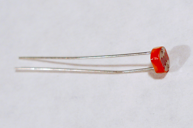
Figure 6. Photocell, or light-dependent resistor Any analog sensor will do the job for this lab.
About mouse control
NOTE: The sketches contained in this lab will cause the Arduino Leonardo to take control of your mouse. Make sure they’re working properly before you add the mouse commands. The example doesn’t introduce the mouse commands until the end of the lab. Instead, messages are printed to the serial monitor to tell you what should happen. When you’ve run this and seen the serial messages occurring when you think they should, then you can add the mouse commands safely.
The sketches here will work on an Uno until you add the mouse commands. So you can test this on an Uno or any board that’s not USB-native simply by commenting out the Mouse.h include at the top of the code below, and any line that says Mouse.begin() or Mouse.move().
Note on Mouse, Keyboard, and Serial Ports
The Mouse and Keyboard libraries on the SAMD boards (MKRZero, MKR1xxx, Nano 33IoT) have an unusual behavior: using them changes the serial port enumeration. When you include the Keyboard library in a sketch, your board’s serial port number will change. For example, on MacOS, if the port number is /dev/cu.usbmodem14101, then adding the Keyboard library will change it to /dev/cu.usbmodem14102. Removing the Keyboard library will change it back to /dev/cu.usbmodem14101. Similarly, if you double-tap the reset button to put the board in bootloader mode, the serial port will re-enumerate to its original number.
Windows and HID Devices
You may have trouble getting these sketches to work on Windows. On Windows, the default Arduino drivers must be uninstalled so the system can recognize the Arduino as both serial device and HID device. Read this issue and follow the instructions there.
Recovering From a Runaway HID (Mouse or Keyboard) Sketch
Programs which control your keyboard and mouse can make development difficult or impossible if you make a mistake in your code. If you create a mouse or keyboard example that doesn’t do what you want it to, and you need to reprogram your microcontroller to stop the program, do this:
Open a new blank sketch.
This sketch is your recovery:
void setup() {

}
void loop() {

}
Programming the board with this blank sketch removes your mistaken sketch and gives you control again. To do this, however, you need the current sketch to stop running. So:
Put the microcontroller in bootloader mode and upload the blank sketch
On the SAMD boards, you can do this by double-tapping the reset button. The on-board LED will begin glowing, and the bootloader will start so that you get a serial port enumeration, but the sketch won’t run. On the Leonardo and other 32U4-based boards, hold the reset down until you’ve given the upload command. The 32U4 bootloader will take a few seconds before it starts the sketch, so the uploader can take command and load your blank sketch.
Once you’ve got the blank sketch on the board, review the logic of your mistaken Keyboard or Mouse sketch and find the problem before uploading again.
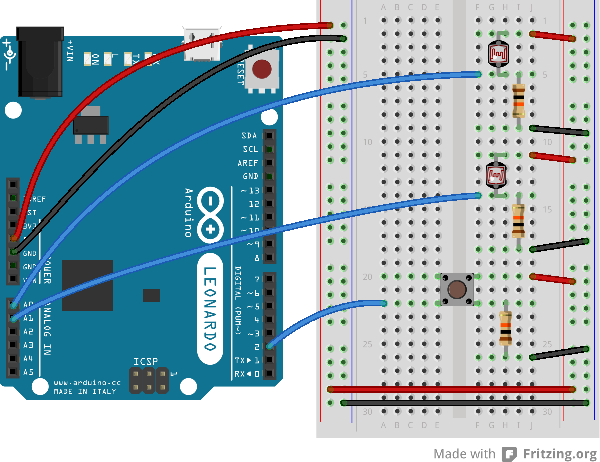
In Figure 7 you see an Arduino Leonardo on the left connected to a solderless breadboard, right. The Leonardo’s 5V output hole is connected to the red column of holes on the far left side of the breadboard. The Leonardo’s ground hole is connected to the blue column on the left of the board. The red and blue columns on the left of the breadboard are connected to the red and blue columns on the right side of the breadboard with red and black wires, respectively. These columns on the side of a breadboard are commonly called the buses. The red line is the voltage bus, and the black or blue line is the ground bus. See Figure 8 for the breadboard view with Arduino Nano.
Figure 7: An Arduino Leonardo on the left connected to a solderless breadboard, right.
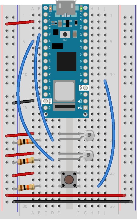
Figure 8 Breadboard view of Arduino Nano mounted on a breadboard.
Figure 8. Breadboard view of an Arduino Nano connected to a breadboard. The +3.3 volts and ground pins of the Arduino are connected by red and black wires, respectively, to the left side rows of the breadboard. +3.3 volts is connected to the left outer side row (the voltage bus) and ground is connected to the left inner side row (the ground bus). The side rows on the left are connected to the side rows on the right using red and black wires, respectively, creating a voltage bus and a ground bus on both sides of the board.
Attach a pushbutton to digital pin 2. Connect one side of the pushbutton to 5 volts, and the other side of the pushbutton to a 10-kilohm resistor. Connect the other end of the resistor to ground. Connect the junction where the pushbutton and the resistor meet to digital pin 2. (For more on this digital input circuit,see the Digital Input Lab)
In Figure 9 and Figure 10 you see a schematic drawing and a breadboard drawing of an Arduino Leonardo connected to a pushbutton. Figure 11 shows the Nano 33 IoT version. The pushbutton straddles the center divide of the breadboard in rows 20 through 22. A red wire connects row 20 on the right center side to the right side voltage bus. A 10-kilohm resistor connects row 22 on the right center side to row 26 on the same side. A black wire connects from row 26 to the ground bus on the right side. A blue wire connects row 22 on the left center side of the board to digital pin 2. See Figure 11 for the breadboard view with Arduino Nano.
Figure 9. Schematic view of an Arduino Leonardo connected to a pushbutton.
Figure 10: Breadboard view of an Arduino Leonardo connected to a pushbutton.
Figure 11. Breadboard view of an Arduino Nano connected to a pushbutton.
Figure 11. Breadboard view of an Arduino Nano connected to a pushbutton. The +3.3 volts and ground pins of the Arduino are connected by red and black wires, respectively, to the left side rows of the breadboard. +3.3 volts is connected to the left outer side row (the voltage bus) and ground is connected to the left inner side row (the ground bus). The side rows on the left are connected to the side rows on the right using red and black wires, respectively, creating a voltage bus and a ground bus on both sides of the board. The pushbutton is mounted across the middle divide of the solderless breadboard. A 10-kilohm resistor connects from the same row as pushbutton’s bottom left pin to the ground bus on the breadboard. There is a wire connecting to digital pin 2 from the same row that connects the resistor and the pushbutton. The top left pin of the pushbutton is connected to +3.3V.
Add two analog inputs
Attach a photoresistor to 5 volts. Attach a 10-kilohm resistor from the other side of the photoresistor to ground. Attach the junction where the photocell and the resistor meet to analog input 0. Do the same for analog input 1. You can use any variable resistor in place of the photoresistors: flex sensors, force-sensing resistors, or whatever feels good to you.
In Figure 12 and Figure 13 you see a schematic drawing and a breadboard drawing of an Arduino Leonardo connected to a pushbutton and two voltage divider inputs. The pushbutton is connected as described in the previous breadboard drawing. Two photoresistors are mounted in the right center section of the breadboard. The first is connected to rows 2 and 5. The second is connected to rows 11 and 14. Rows 2 and 11 are also connected to the right side voltage bus through red wires. Two 10-kilohm resistors are also mounted in the right center section. The first is connected to rows 5 and 9, and the second is connected to rows 14 and 18. Rows 9 and 18 are connected to the right side ground bus. The four resistors thus form two voltage dividers. A blue wire extends from the middle of each divider to the analog pins. The first goes from row 5 to pin A0, and the second from row 14 to pin A1. See Figure 14 for the breadboard view with Arduino Nano.
Figure 12. Schematic view of an Arduino Leonardo connected to a pushbutton.
Figure 13: Breadboard view of an Arduino Leonardo connected to a pushbutton and two voltage divider circuits.
Figure 14. Breadboard drawing of an Arduino Nano connected to a pushbutton and two phototransistors.
Figure 14. Breadboard drawing of an Arduino Nano connected to a pushbutton and two phototransistors. The pushbutton connects remain the same as described in the previous diagram. The short legs of the phototransistors connect to the voltage bus. The longer legs of each phototransistor each connect a 10-kilohm resistor to the ground bus and a blue wire to the analog pins of the Arduino Nano, the first goes to pin A0, and the second to pin A1.
Program the module to read the pushbutton
In the Digital Lab you learned how to read a pushbutton using the digitalRead() command. To tell when a pushbutton is pushed, you need to determine when the button’s state changes from off to on. With the pushbutton wired as you have it here, its state will change from 0 to 1. In order to know that, you need to know not only what the current state of the button is, but you also need to remember the state of the button the previous time you read it.
To do this, set up a global variable to store the button’s previous state. Initialize the button in your program’s setup() function using the pinMode() command. Then, in the loop() function, write a block of code that reads the button and compares its state to the previous state variable. To do this, you need to read the button, check the current button state against the last state, then save the current state of the button in a variable for the next time through the loop like so:
int lastButtonState = LOW;        // state of the button last time you checked

void setup() {
  // make pin 2 an input:
  pinMode(2, INPUT);
}

void loop() {
  // read the pushbutton:
  int buttonState = digitalRead(2);

  // check if the current button state is different than the last state:
  if (buttonState != lastButtonState) {
     // do stuff if it is different here
  }

  // save button state for next comparison:
  lastButtonState = buttonState;
}
If buttonState is not equal to lastButtonState, then the button has changed. Then you want to check if the current state is HIGH. If it is, then you know the button has changed from low to high. That means your user pressed it. Print out a message to that effect.
int lastButtonState = LOW;        // state of the button last time you checked

void setup() {
  // initialize serial communication:
  Serial.begin(9600);
  // make pin 2 an input:
  pinMode(2, INPUT);
}

void loop() {
  // read the pushbutton:
  int buttonState = digitalRead(2);

  // if it's changed and it's high, toggle the mouse state:
  if (buttonState != lastButtonState) {
    if (buttonState == HIGH) {
      Serial.println("Button was just pressed.");
    }
  }
  // save button state for next comparison:
  lastButtonState = buttonState;
}
Your code should only print out a message when the button changes state. For every button press, you should get one line of code. If you’re getting multiple lines of code for every button press, you did it wrong.
Set up a variable to track whether or not you’re controlling the mouse
This sketch is going to take control of your computer’s mouse when you finish it. If you get it wrong, that can cause real problems, because you won’t be able to control your computer until you unplug the Leonardo. So you want to make sure you’ve got a way to turn off control of the mouse. You’ll use this pushbutton to turn on or off the Leonardo’s control of the mouse.
To do this, set up a global variable called mouseIsActive. Initialize it as false. When the button is pressed, change this variable from false to true, or true to false, depending on its state. This should be a boolean variable. This variable doesn’t actually change anything yet, but later on, you’ll decide whether to issue mouse movement commands depending on whether it’s true or false.
// Global variables:
int lastButtonState = LOW;            // state of the button last time you checked
boolean mouseIsActive = false;    // whether or not the Arduino is controlling the mouse

void setup() {
  // initialize serial communication:
  Serial.begin(9600);
  // make pin 2 an input:
  pinMode(2, INPUT);
}

void loop() {
  // read the pushbutton:
  int buttonState = digitalRead(2);

  // if it's changed and it's high, toggle the mouse state:
  if (buttonState != lastButtonState) {
    if (buttonState == HIGH) {
      // if mouseIsActive is true, make it false;
      // if it's false, make it true:
      mouseIsActive = !mouseIsActive;
      Serial.print("Mouse control state: ");
      Serial.println(mouseIsActive);
    }
  }
  // save button state for next comparison:
  lastButtonState = buttonState;
}
Read the sensors and decide on a threshold for action
The photoresistors in the circuit above will be used to detect whether the user wants to move left or right. Set them up close to each other in the same light. When the user waves her hand over the top one in the image above, you’ll move the mouse cursor to the left, and when she waves her hand over the bottom one, you’ll move it to the right. Nothing should happen if she doesn’t have her hands over the sensors, or if she has her hands over both sensors.
Since they’re in the same light, they should read identically. So to detect hands, you want to look for a significant difference between the sensors. When there’s a significant difference between them, you’ll make a move. When the top sensor is higher, you’ll move to the left. When the one on the bottom is higher, you’ll move to the right.
Add code to the main loop to read the sensors into two variables, sensor1 and sensor2, with a one-millisecond delay between readings. Then print the results.
// Global variables:
int lastButtonState = LOW;            // state of the button last time you checked
boolean mouseIsActive = false;    // whether or not the Arduino is controlling the mouse

void setup() {
  // initialize serial communication:
  Serial.begin(9600);
  // make pin 2 an input:
  pinMode(2, INPUT);
}

void loop() {
  // read the pushbutton:
  int buttonState = digitalRead(2);

  // if it's changed and it's high, toggle the mouse state:
  if (buttonState != lastButtonState) {
    if (buttonState == HIGH) {
      // if mouseIsActive is true, make it false;
      // if it's false, make it true:
      mouseIsActive = !mouseIsActive;
      Serial.print("Mouse control state: ");
      Serial.println(mouseIsActive);
    }
  }
  // save button state for next comparison:
  lastButtonState = buttonState;

// read the analog sensors:
  int sensor1 = analogRead(A0);
  delay(1);
  int sensor2 = analogRead(A1);

  // print their values:
  Serial.print(sensor1);
  Serial.print("  ");
  Serial.println(sensor2);
}
Right after this in the main loop, add code to compare the two values. If there is more than 100 points difference, print L or R, depending on which sensor is higher (L for the top sensor, R for the bottom):
// if there's a significant difference to the right:
  if (sensor1 > sensor2 + 100) {
    Serial.println("L");
  }

  // if there's a significant difference to the left:
  else if (sensor2 > sensor1 + 100) {
    Serial.println("R");
  }
When you run this sketch now, you should see an L or R every time there’s a significant difference (> 100) between the sensors. When you push the button, you should get a report of the mouse control state, 1 for true and 0 for false. Run it and open the serial monitor to see that happen.
Add mouse control
Now it’s time to add mouse control commands.
NOTE: The sketches contained in this lab will cause the Arduino Leonardo to take control of your mouse. Make sure they’re working properly before you add these commands. The example doesn’t introduce the mouse commands until the end of the lab. Instead, messages are printed to the serial monitor to tell you what should happen. When you’ve run this and seen the serial messages occurring when you think they should, then you can add the mouse commands safely.
The sketches here will work on an Uno until you add the mouse commands. So you can test this on an Uno simply by commenting out any line that says Mouse.begin() or Mouse.move().
If your sketch causes your mouse to misbehave, upload a blank sketch (the default when you choose File -> New) to your Leonardo and you can start again from the beginning.
The Mouse.begin() command is called in the setup. It initializes mouse control from your Leonardo.
The Mouse.move() command has three parameters: the horizontal movement, the vertical movement, and the scroll wheel movement. All movements are relative, so Mouse.move(1,0,0); moves one pixel to the right; Mouse.move(-1,0,0); moves one pixel to the left; Mouse.move(0,1,0); moves one pixel down; and Mouse.move(0,-1,0); moves one pixel up.
At the top of your code, include the Mouse library. Then Modify the setup by adding the command Mouse.begin(). Then, in the loop where you print L or R, add Mouse.move commands to move left or right, as needed.
#include "Mouse.h"                // include the mouse library
// Global variables:
int lastButtonState = LOW;        // state of the button last time you checked
boolean mouseIsActive = false;    // whether or not the Arduino is controlling the mouse

void setup() {
  // initialize mouse control:
  Mouse.begin();
  // initialize serial communication:
  Serial.begin(9600);
  // make pin 2 an input:
  pinMode(2, INPUT);
}

void loop() {
  // read the pushbutton:
  int buttonState = digitalRead(2);

  // if it's changed and it's high, toggle the mouse state:
  if (buttonState != lastButtonState) {
    if (buttonState == HIGH) {
      // if mouseIsActive is true, make it false;
      // if it's false, make it true:
      mouseIsActive = !mouseIsActive;
    }
  }
  // save button state for next comparison:
  lastButtonState = buttonState;

  // read the analog sensors:
  int sensor1 = analogRead(A0);
  delay(1);
  int sensor2 = analogRead(A1);

  // print their values. Remove this when you have things working:
  Serial.print(sensor1);
  Serial.print("  ");
  Serial.println(sensor2);

  // if there's a significant difference to the right:
  if (sensor1 > sensor2 + 100){
    //  Serial.println("L");
    if (mouseIsActive == true) {
      Mouse.move(-1, 0, 0);
    }
  }

  // if there's a significant difference to the left:
  else if (sensor2 > sensor1 + 100) {
    // Serial.println("R");
    if (mouseIsActive == true) {
      Mouse.move(1, 0, 0);
    }
  }
}
That’s the whole sketch. When you run this, press the button to enable or disable mouse control, then put your hands over the sensors to move the mouse left or right.