Pedro Oliveira
pedro.itp(at)nyu.edu
Office hours
NYU ITP, Fall 2023
TUE 3:20-5:50pm
Class Links
Useful Links
How to Use the Website
The ITP Pcomp website has a wealth of information that is organized in 3 ways:
- The Week-to-Week gives a chronological run down of all the subject matter that will be covered as we move through the semester, as well as assignments and labs that you must do on your own.
- The Lessons, Videos, and Labs pages covers a lot of the same information, but organized by subject matter and in different formats.
- The Resources section contains information that are useful for physical computing in general, like suppliers, links to other useful sites, recommended tools and parts to get started, and more.
Documentation
Document your progress in the class online in a regular blog as you go. At a minimum, you should summarize any insights and questions you have from each week’s lab assignments, and document your production projects and technical research thoroughly. You can find guidelines for good documentation, and several examples, on the Journals & Documentation page.
Setup your blog and add the link to this spreadsheet, please. (You will need to log in with your NYU account).
Class Notes
(Here is where you will find the class Notes)
Class 01
Formula:
INPUT -> COMPUTATION -> OUTPUT
Class 03
Digital Input and Digital Output
// OUTPUT / INPUT
pinMode(13, OUTPUT);
pinMode(2, INPUT);

// Write / Read
digitalWrite(13, HIGH);
digitalRead(2);
Digital IO Examples:
Class 04
Analog Input and “Analog Output” (PWM)
// You do not need to call pinMode() to set the pin as an Analog Input or Analog Output(PWM).

// Write / Read
analogWrite(9, 150);  // ~PWM Pin  (Output)
analogRead(A0);       // Analog Pin (Input)
Analog IO Examples:
Tone Example:
Class 05
Class 06
Examples:
- 018_Math
- 019_Map
- 020_ServoPos
- 021_ServoPot
- 022_ServoConsole
- 023_ServoSerial
- 024_DCMotorPWM
- 025_DCMotorSerial
- 026_StepperMotor
- 026_StepperSerial
Class 07
For week 8:
- Document your Midterm project and update on your blog
- Upload the feedback to this [link]
Class 08
Serial Communication
// Sets the data rate in bits per second (baud) for serial data transmission. For communicating with Serial Monitor, make sure to use one of the baud rates listed in the menu at the bottom right corner of its screen. You can, however, specify other rates - for example, to communicate over pins 0 and 1 with a component that requires a particular baudrate.

Serial.begin(9600);

// Writes binary data to the serial port. This data is sent as a byte or series of bytes; to send the characters representing the digits of a number use the print() function instead.

Serial.write(45);

// Prints data to the serial port as human-readable ASCII text. This command can take many forms. Numbers are printed using an ASCII character for each digit. Floats are similarly printed as ASCII digits, defaulting to two decimal places. Bytes are sent as a single character. Characters and strings are sent as is

Serial.print('A');

// Prints data to the serial port as human-readable ASCII text followed by a carriage return character (ASCII 13, or '\r') and a newline character (ASCII 10, or '\n'). This command takes the same forms as Serial.print().

Serial.println("Hello");

// Reads incoming serial data.

Serial.read();
Serial Communication Examples:
- Arduino -> p5js // Single Value
- Arduino -> p5js // Parse Multiple Values
- p5js <-> Arduino // Send and Receive
Class 09
Serial Communication
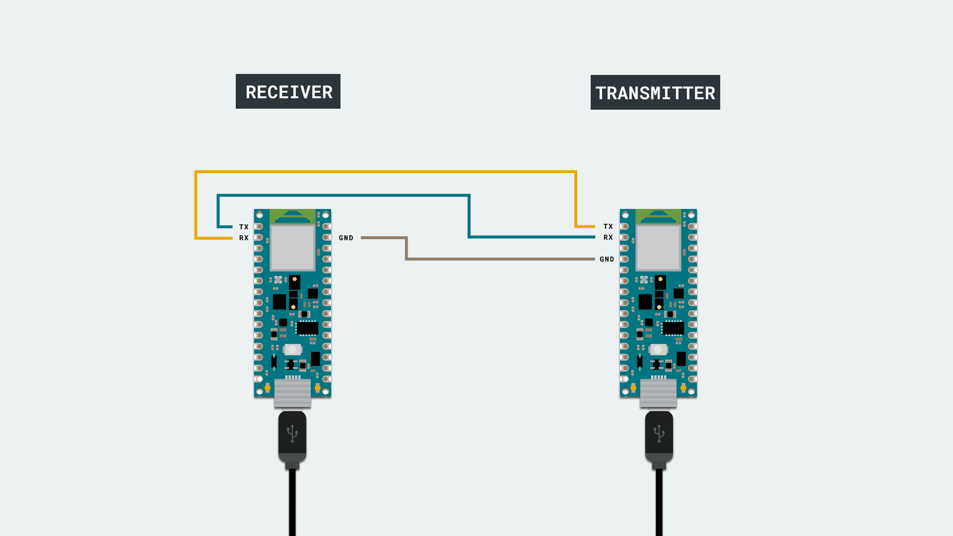
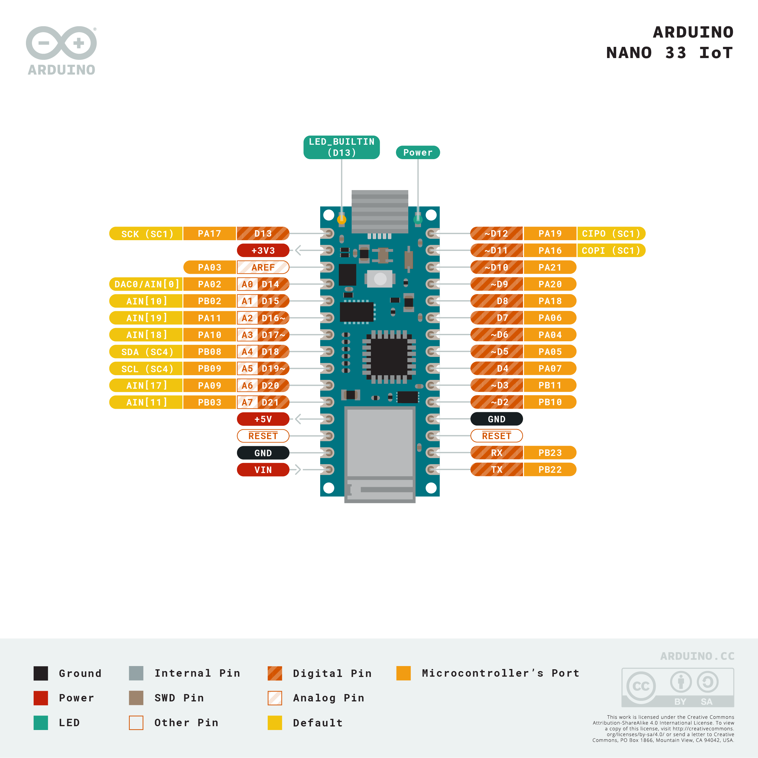
// UART is the communication protocol we use to communicate the PC to the board through the USB cable. In some older boards, TX and RX pins are used for communication with the computer, which means connecting anything to these pins can interfere with that communication, including causing failed uploads to the board. This is not the case for the Nano or MKR families, since these ones have two separate channels, using Serial for the communication with the computer and Serial1 for the communication with any other device through UART.

// Serial through the USB cable
Serial.begin(9600);

// Serial through the pins RX and TX (Nano 33 IOT)
Serial1.begin(9600);
Class 10
Final Proposals [link]
Class 11
USB – HID
A note from Tom: “All Arduinos appear to your personal computer’s operating system as an asynchronous serial port, sometimes called a COM port or Universal Asyncronous Receiver-Trasmitter (UART). This is its USB profile, and when you plug it into your computer, the operating system notes that profile and adds it to the list of USB devices. When you program an Arduino to behave as an HID device, you’re giving it an additional USB profile.
When you include the Keyboard library in a sketch, your board’s serial port number will change. For example, on MacOS, if the port number is /dev/cu.usbmodem14101, then adding the Keyboard library will change it to /dev/cu.usbmodem14102. Versions of the Arduino IDE from 1.8.13 and higher will automatically adjust the serial port selected when you do this, but earlier versions won’t, and other applications using the serial port won’t, so you might need to make the adjustment yourself.”