These notes are heavily indebted to Gordon McComb’s Robot Builder’s Bonanza, second edition, which includes some excellent chapters on motors and motor use.
Introduction
Related video: Meet the Motors
When trying to move things with microcontrollers, you’re likely to use one of three kinds of motors: DC motors, RC servomotors, and stepper motors. Following is a brief introduction to these three. In order to get the most out of these notes, you should know something about how electricity works, and you should know the basics of how a microcontroller works as well. You should also understand how transistors are used to control high-current loads.
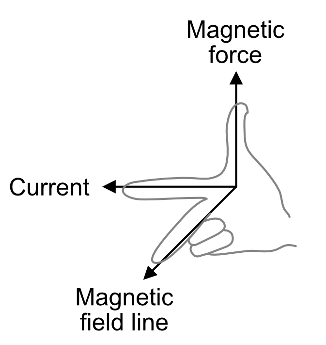
Motors convert electrical energy into mechanical energy so that you can move things in the physical world. They are based on the electrical principle of induction. When you put electric current through a wire, it generates a magnetic field around the wire as shown in Figure 1. The direction of the magnetic field is related to the direction of the electrical current. It’s often described as the right-hand rule. If you hold your right hand up and put your thumb perpendicular to your index finger, then put your middle finger perpendicular on the other axis, can see the directions of current flow (your index finger); magnetic force (your thumb); and the magnetic field line (your middle finger). The higher the current, the greater the magnetic field, and therefore the greater the attraction or repulsion.
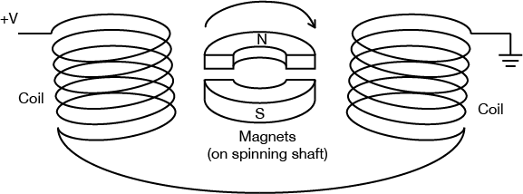
Similarly, if there’s a magnet near a wire, its field will interact with the wire’s magnetic field and generate a current in the wire. If you mount magnets on a spinning shaft surrounded by the wire, you have a motor. In Figure 2, the wire is arranged in two coils. As the magnets are alternately attracted to one coil and repulsed by the other, it spins from one to the other, and you get circular motion. Figure 2 illustrates the basic mechanism of a DC motor.
All inductive loads (like motors, electromagnets, and solenoids) work on this same principle: induce a magnetic field by putting current through a wire, use it to attract or repulse a magnetic body. However, the principle works in reverse as well. When you spin a wire in an existing magnetic field, the field induces a current in the wire. So if you’ve got a motor spinning, and you turn it off, the fact that the motor’s coil is spinning in a magnetic field will generate a current in the wire while it’s spinning. You can test this by attaching an LED to the two leads of a DC motor and spinning the motor by hand. Spun in one direction, the LED will light. Spin in the other, the LED won’t light.
This generated current comes back in the reverse direction of the current flow you generated to run the motor. When the motor isn’t attached to another source of electricity, you’d call this a generator as in the LED experiment, because the motor is now generating voltage. When the motor is connected to another power source, it’s called back voltage, and it can cause damage to your electronics. Usually it’s stopped by putting a diode in parallel with your motor to route the back voltage through the diode.
Motor Characteristics
There are a few characteristics common to all motors that you should keep in mind when looking for motors:
Voltage
The rated voltage of a motor is the voltage at which it operates at peak efficiency. Most DC motors can be operated somewhat above or below their range, but it’s best to plan to operate them at their rated voltage. Dropping below rated voltage reduces the motor’s power, and operating above the rated voltage may burn the motor out. Plan on the motor’s top speed being at rated voltage, and slowest speed at no more than 50% less than the rated voltage.
Current
Motors draw current depending on the load they’re pulling. Usually more load means more current. Every motor has a stall current, which is the current it draws when it’s stopped by an opposing force. This stall current is generally much greater than the running current, or current that the motor draws under no load. Your power supply for a motor should be able to supply the stall current with extra amperage to spare. Motors will draw the stall current for a brief period of time when starting up, to overcome their inertia.
Speed
Motor speed is given in revolutions per minute (RPMs). At the rated voltage, your motor should be turning at the rated speed.
Torque
Torque is the measure of a motor’s turning force. It’s the force a motor can pull when the opposing force is attached to a shaft attached to its center rod. If the shaft sticks out a foot from the motor’s center, and the motor can pull one pound on that shaft, the motor’s torque is one foot-pound. Figure 3 illustrates this with a motor that supplies 1g*cm. Related video: Torque and Gearboxes

Resistance
Often you’ll see a motor rated in ohms. This just gives you the resistance that the motor’s coil offers. Using Ohm’s Law (voltage = current x resistance), you can calculate the motor’s current draw if you know the rated voltage and the coil resistance.
Types of Motors
DC Motor
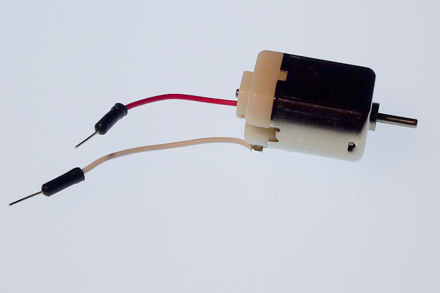
The DC Motor is the simplest of the motors discussed here. Figure 4 shows a photo of a small DC motor. It works on exactly the principle discussed above. There are two terminals, and when you apply direct current to one terminal and ground the other, the motor spins in one direction. When you apply current to the other terminal and ground the first terminal, the motor spins in the opposite direction. By switching the polarity of the terminals, you reverse the direction of the motor. By varying the current supplied to the motor, you vary the speed of the motor. Specific techniques for doing these tasks are discussed below. Related video: Power to a DC Motor
DC motors are usually very fast, often spinning at several thousand revolutions per minute (RPM). The DC motor in Figure 4 is common to many toy and hobby projects.
For more on DC motor control, see this lab for single-direction control, or this lab for controlling a motor in two directions with an H-Bridge.
Gearhead Motor
Gearhead motors are a subset of DC motors. Figure 7 is a drawing of a gearhead motor. They have a box on the top of the motors containing a series of gears that slow the rotational speed of the motor down and increase the torque. They are useful when you don’t need a lot of speed, but you do need power. They are controlled exactly the same as regular DC motors.
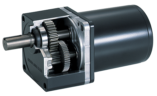
In Figure 8, you can see a gearmotor that uses this size motor. You can see the full specifications at this link. Table 1 has a summary of the specs. You can see that the no-load current is 190mA and the stall current is 250mA. and the rated voltage is 6V. Using this information, you could work out that the coil resistance is probably between 24 and 32 ohms. You can also see that the no-load speed is 230RPM and the stall torque is 0.8 kg-cm. These are the values for the motor with the gearbox attached.
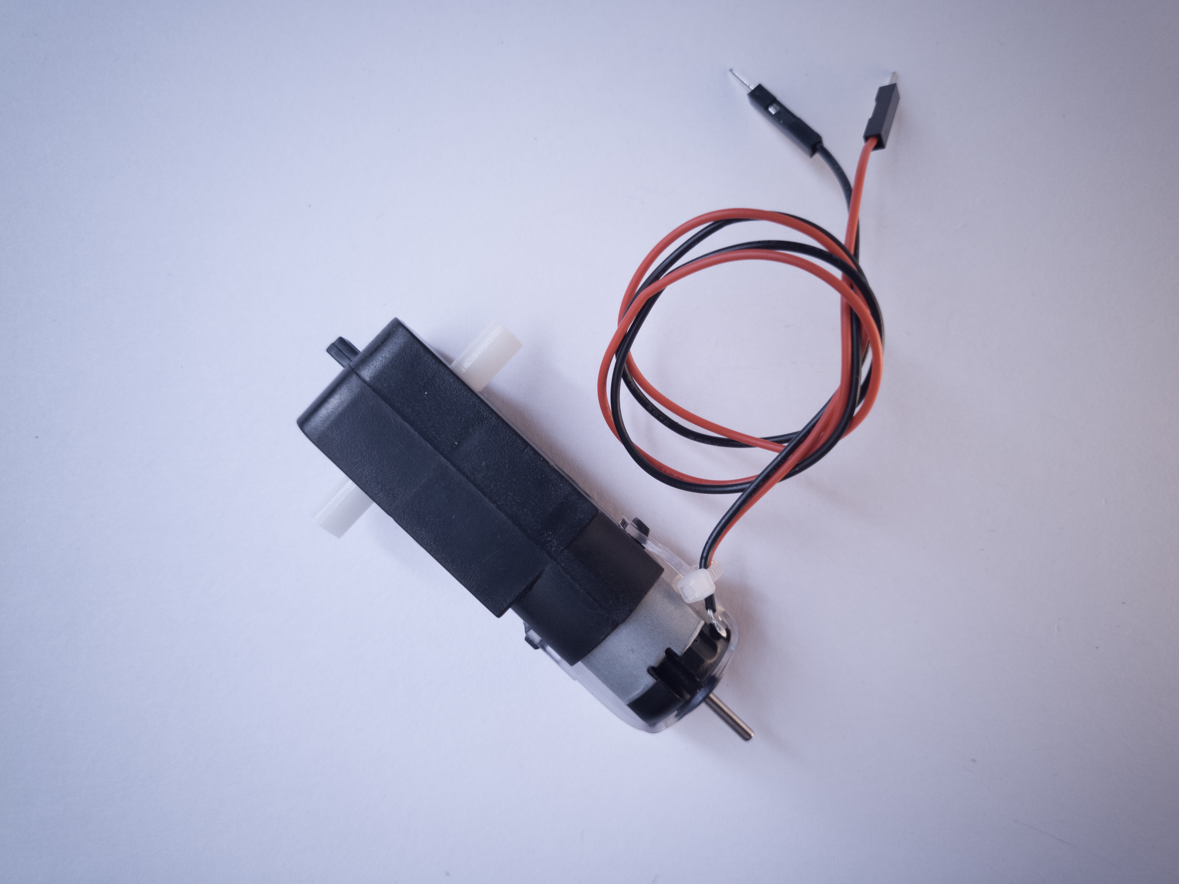
| Voltage (Nominal) | 6VDC |
|---|---|
| No-Load Speed @ 6VDC | 230RPM |
| No-Load Current @ 6VDC | 190mA |
| Stall Current @ 6VDC | 250mA |
| Stall Torque @ 6VDC | 11.11 oz-in (0.8 kg-cm) |
| Gear Ratio | 48:1 |
DC Motor Control
There are two easily controllable parameters of a DC motor, direction and speed. To control the direction, you reverse the direction of the voltage through the motor. To control the speed, you pulse width modulate it.
Direction
To control a DC motor from a microcontroller, you use switching arrangement known as an H-bridge, consisting of four switches with the motor in the center. Figure 9 is the schematic for a typical H-bridge:
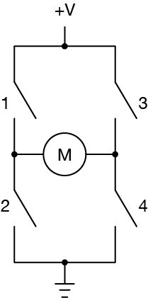
When switches 1 and 4 are closed and 2 and 3 are open, voltage flows from the supply to 1 to the motor to 4 to ground. When 2 and 3 are closed and 1 and 4 are open, polarity is reversed, and voltage flows from the supply to 3 to the motor to 2 to ground. Related video: H-Bridge
An H-bridge can be built from transistors, so that a microcontroller can switch the motor, like this in Figure 10:
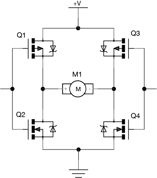
This schematic uses MOSFETs, which are good for controlling motors. The top two transistors above are P-channel, meaning that they allow current to pass when the gate voltage is low rather than high. The bottom two are N-channel, so that the proper two transistors always switch together. When the left control pin is high, transistor 1 (labeled Q1) turns off because it’s a P-channel and Q2 turns on because it’s an N-channel. The same happens with Q3 and Q4. If you were using this circuit, you’d want to make sure that the control pins are always reversed; when one is high, the other is low. Related video: MOSFET Transistor
Although you can make your own H-bridges, it’s usually easier to use a controller manufactured specifically for the job. A pre-manufactured H-bridge chip will include diodes to protect the transistors from back voltage, sometimes a current sensing pin to sense the current the motor is drawing, and much more. There are many motor drivers available from various electronics suppliers. Look around to find one that suits your needs and price range.
Speed
A DC motor’s speed is proportional to the supplied voltage. If the voltage drops too far, the motor won’t get enough power to turn, but within a certain range, usually 50% of the rated voltage, the motor will run at varying speeds. The most effective way to adjust the speed is by using pulsewidth modulation. This means that you pulse the motor on and off at varying rates, to simulate a voltage. Related video: Why use PWM on DC Motors?
RC Servomotor
Servo motors are a variation on the gearhead motor coupled with a potentiometer to give feedback on the motor’s position. Figure 11 shows a photo of a small servomotor. The gears of the gearbox on a servo are attached to a potentiometer inside the case, and the pot is turned by the turning of the motor. The pot is connected to a capacitor in a resistor-capacitor circuit (R-C), and by pulsing this R-C circuit, you give the motor power to turn. When the motor turns, it changes the resistance of the R-C circuit, which in turn feeds the motor again. By pulsing the R-C circuit, you set the motor’s position in a range from 0 to 180 degrees. Related video: Meet the motors – servomotor
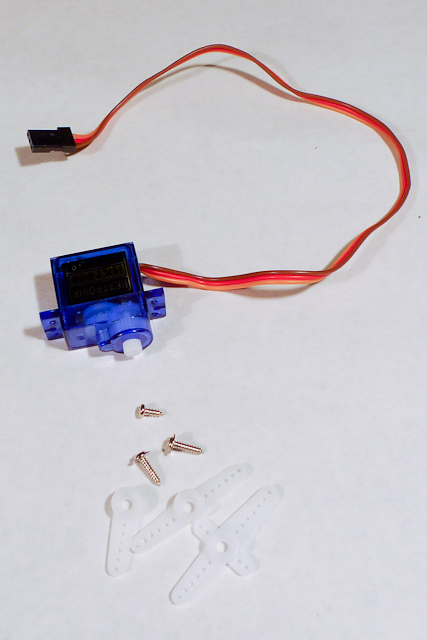
Servos have three wires to them, unlike most DC and gearhead motors, which have two. The first two in a servo are power and ground, and the third is a digital control line. This third line is used to set the position of a servo. Unlike other DC motors, you do not have to reverse the polarity of a servo’s power connections to reverse its direction.
Hobby servos, the kind most often used in small physical computing projects, usually take a pulse of between 1-2 ms every 18-20 ms. They rotate 0 to 180 degrees depending on the pulsewidth. A pulse of 1 ms will turn the motor to 0 degrees; 2 ms will turn it to 180 degrees. A servo needs to see a pulse every 18-20 ms even when it is not turning, to keep it in its current position, so once you’ve moved the motor to a new position, it’s essential to keep pulsing it with the same pulsewidth to keep it there.
For more on Servo motor control, see this lab: Servo Motor Control with an Arduino, and this video: Analog Output – Servo
Stepper Motor
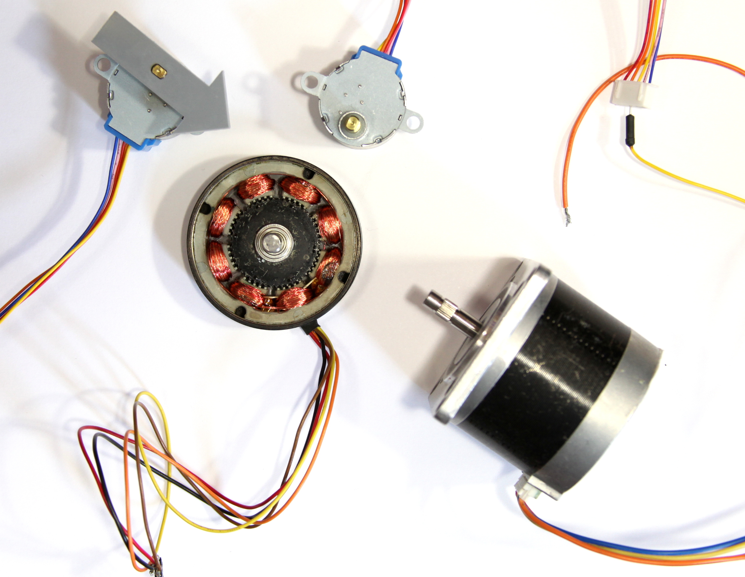
Stepper motors are different than regular DC motors in that they don’t turn continuously, but move in a series of steps. A stepper motor is a motor that has multiple coils, not just one. By energizing each coil in sequence, you attract the shaft magnets to each coil in the sequence, and you can turn the motor in precise steps, rather than simply rotating continually. Figure 12 shows photos of stepper motors in varying sizes.
This design allows for very precise control of the motor: by proper pulsing, it can be turned in very accurate steps of set degree increments (for example, two-degree increments, half-degree increments, etc.). They are used in printers, disk drives, and other devices where precise positioning of the motor is necessary. Steppers usually move much slower than DC motors, since there is an upper limit to how fast you can step them (5-600 pulses per second, typically. However, unlike DC motors, steppers often provide more torque at lower speeds. They can be very useful for moving a precise distance. Furthermore, stepper motors have very high torque when stopped, since the motor windings are holding the motor in place like a brake.
To control a stepper, you use stepper driver that will energize the coils in the right order to make the motor move forward. There are plenty of libraries and driver modules and ICs that simplify the process. What follows is a low-level explanation of how steppers work.
Stepper Motor Control
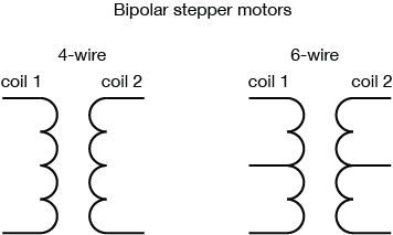
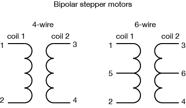
There are two types of stepper motors, called unipolar and bipolar. The difference is in their wiring. Unipolar steppers have all of their coils joined by a center wire. Bipolar steppers have two coils, which are not joined. Unipolar motors typically have five wires, while bipolars have four or six wires. Unipolar stepper motor’s wiring works as shown in Figure 13:
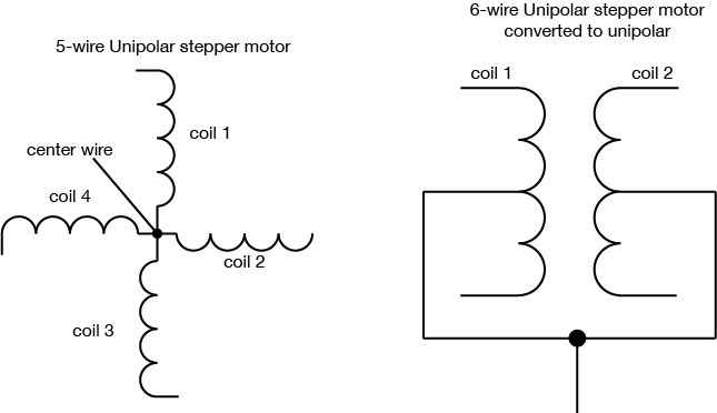
The extra two wires in a 6-wire bipolar stepper allow you to use it as a 4-coil motor instead of a 2-coil, by using the center wire on each coil as a common supply or ground. In addition, you can turn a 6-wire bipolar into a 5-wire unipolar by joining the two center wires as shown in Figure 14:
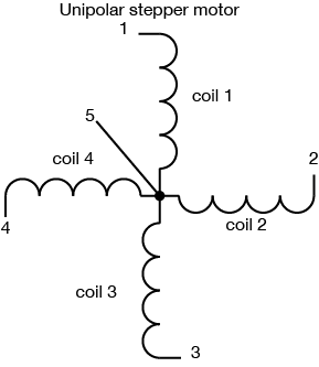
To determine which wire is which, measure the resistance of the coils. In a bipolar motor, the two coils will have the same resistance, and they are not connected to each other. So if you see infinite resistance, you have two wires on separate coils. When you find two pairs that have the same resistance, you’ve found the two coils of your bipolar stepper. In a six-wire bipolar motor, the resistance between the outside wires of a coil will be twice what it is between the center wire and either outer wire. In a unipolar stepper, the resistance between the center wire and any of the other four will be the same, and the resistance between any two outer wires will be twice what it is from the center wire to any of the outer wires, as shown in Figure 15 and Figure 16:
Like other motors, the stepper requires more power than a microcontroller can give it, so you’ll need a separate power supply for it. Ideally you’ll know the voltage from the manufacturer, but if not, get a variable DC power supply, apply the minimum voltage that the supply can generate voltage across two wires of a coil (e.g. 1 to 2 or 3 to 4) and slowly raise the voltage until the motor is difficult to turn. It is possible to damage a motor this way, so don’t go too far. Typical voltages for a stepper might be 5V, 9V, 12V, 24V. Higher than 24V is less common, and frankly, above that it’s best not to guess. Related video: Connect 12V Power Supply
To power each coil, you supply voltage one side of the coil while grounding the other side. Typically, you drive a stepper motor with an H-bridge or an array of power transistors or MOSFETS.
To move the stepper, you apply voltage to each of the coils in a specific sequence. Typical phasing could go as shown in Table 2
| Step | Wire 1 | Wire 2 | Wire 3 | Wire 4 |
|---|---|---|---|---|
| 1 | high | low | high | low |
| 2 | low | high | high | low |
| 3 | low | high | low | high |
| 4 | high | low | low | high |
Once you have the motor stepping in one direction, stepping in the other direction is simply a matter of doing the steps in reverse order. Knowing the position is a matter of knowing how many degrees per step, and counting the steps and multiplying by that many degrees. So for examples, if you have a 2-degree stepper, and it’s turned 180 steps, then it’s turned 2 x 180 degrees, or 360 degrees, or one full revolution.
For more on stepper control, see the notes on stepper motor control and this lab: Controlling a Stepper Motor With an H-Bridge.
For a more technical discussion of stepper motor control, see Control Of Stepping Motors, a tutorial, by Douglas W. Jones.