Introduction
Adapted from Understanding Electricity
In order to understand how electronic circuits work, and how to use them to build physical interfaces to digital systems using microcontrollers, there are some basic terms, relationships, and components that you need to know about. What follows is a brief introduction to those terms.
You won’t need to know anything about electricity or electronics to understand this page.
Definitions
Electricity is the flow of electrical energy through conductive materials. An electrical circuit is made up of two elements: a power source and components that convert the electrical energy into other forms of energy. We build electrical circuits to do work, or to sense activity in the physical world.
Sensors are components that convert other forms of energy into electrical energy so we can read the changes in those other forms. Switches, knobs, light and motion sensors all fit in this category. Actuators are components that convert electrical energy into other forms. Light bulbs, motors, LEDs, and heaters are all actuators.
Electronics refers to reading changes in electrical properties as information. For example, a microphone changes sound pressure waves in the air to a changing electrical voltage. This process of changing one energy into another is called transduction, and devices that do it are called transducers. Much of the technical work of physical computing is about figuring out what forms of energy a person is generating, and what kind of transducer you can buy or build to read that energy. In order to do that, though, it’s necessary to understand a few things about electricity. Following are a few terms we’ll use to refer to electrical properties and components. After that, we’ll talk about the important relationships between some of these terms.
Voltage is a measure of the difference in electrical potential energy between two points in a circuit. It is measured in Volts.
Current is a measure of the magnitude of the flow of electrons through a particular point in a circuit. It is measured in Amperes, or Amps.
Resistance is a measure of a material’s ability to oppose the flow of electricity. It is measured in Ohms.
To understand the relationship between voltage, current, and resistance, imagine an avalanche of snow on a mountain. The height of the mountain is analogous to the voltage; the higher the mountain, the more potential energy the falling material has. The amount of snow and rocks in the avalanche is analogous to the current. And the steepness of the mountain is analogous to the resistance: the steeper the mountain, the less it will resist the flow of the snow and rocks. We’ll define this a bit more formally below.
Every circuit has to have a source of electrical energy and a load that uses the energy.All of the electrical energy in a circuit has to get used by the load. The load will convert the electrical energy to some other form of energy, A circuit with no load is called a short circuit. In a short circuit, the power source feeds all of its power through the wires and back to itself, and either the wires melt (if you’re lucky), or the battery and the components blow up.
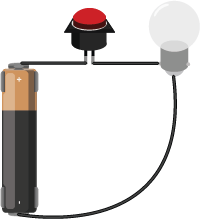
Figure 1 is a very basic circuit, consisting of a lamp, a pushbutton, and a battery. The battery is the source and the lamp is the load. The electrical energy coming from the battery is converted to heat and light energy by the light bulb. All of the energy is used up in the process. However, if the bulb cannot take the voltage produced by the battery (for example, a 6V lamp and a 9V battery), the lamp’s filament will melt trying to transduce all the electrical energy into light and heat.
There are two common kinds of circuits: Direct Current (DC), and Alternating Current (AC). In a DC circuit, current always flows one direction. In an AC circuit, the direction of current flow is reversed in a regular repeating cycle. Most of the circuits we’ll talk about in this class will be DC circuits.
Schematic diagrams are diagrams of circuits that represent the electrical relationships between the components in the circuit. A schematic doesn’t always show the spatial arrangement of the components; it’s arranged so that you can best understand the flow of the electricity. You can find a large collections of schematic symbols in SVG format, useful for drawing your own, on the Wikipedia page for “Electronic Symbol”. An SVG collection of them in one file, convenient for editing into your own diagrams, can be found on this Wikimedia commons page. The symbols for the components you’ll use most commonly in this class are shown below as well.
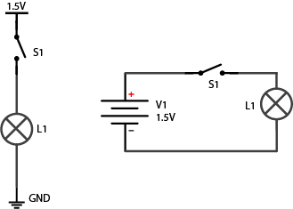
Figure 2 show two schematics of the light bulb circuit above. In both, the important parts to note are the functional components, namely the lamp and the switch, and the power and ground terminals. In the diagram on the right, the whole circuit is shown as a loop, with the battery (marked V1) to the left of the loop. In the diagram on the left, the circuit is not shown as a loop. Instead, the power source is at the top, and the point of lowest energy, or ground, is at the bottom. This diagram shows the flow of energy from the top of the diagram to the bottom. Related Video: Intro to Schematics
Components
Conductors are materials through which electrical current moves freely.
Insulators are materials which prevent the flow of electricity.
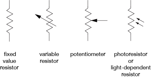
Resistors resist, but do not totally block, the flow of electricity. They are used to control the flow of current. Current can move either way through a resistor, so it doesn’t matter which way they’re connected in a circuit. Resistors are measured by their resistance in ohms (Ω), often seen in kilohms (kΩ). They are symbolized as shown in Figure 3:
Related videos: Resistors, variable resistors, and photocells; Potentiometer
There are many different types of variable resistors, including:
- Thermistors change resistance in reaction to varying temperature;
- Photoresistors change resistance in reaction to varying light;
- Flex sensors change resistance in reaction to being bent or flexed;
- Force sensing resistors change resistance in reaction to a force placed upon them;
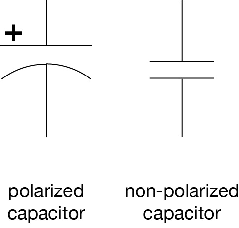
Capacitors store up electricity while current is flowing into them, then release the energy when the incoming current is removed. Capacitors are measured by their capacitance in farads (F), most commonly seen in microfarads (µF). Sometimes they are polarized, meaning current can only flow through them in a specific direction, and sometimes they are not. If a capacitor is polarized, it will be marked as such on the diagram. Don’t wire a polarized capacitor backwards; this can damage the capacitor, and your circuit. Capacitors are also rated by their maximum voltage. Don’t apply more voltage to a capacitor than it’s rated for, or it will explode.
Capacitors are symbolized as shown in Figure 4:
Related video: Capacitors
Diodes permit the flow of electricity in one direction, and block it in the other direction. Because of this, they can only be placed in a circuit in one direction. Light-Emitting Diodes (LED’s) are special types of diodes which emit light when current flows through them. Diodes are symbolized as shown in Figure 5:
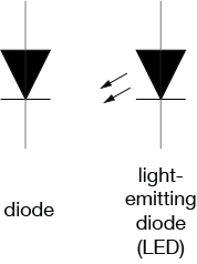
Related video: Diodes and LEDs
Switches and pushbuttons control the flow of current through a junction in a circuit, as shown in Figure 6:
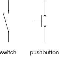
Related video: Switches
Transistors and relays are electrical switching devices, as shown in Figure 7:
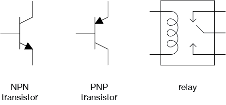
Related video: Relays
Piezoelectric devices create a varying voltage in reaction to slight changes in pressure.
Relationships
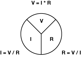
Voltage (V), Current (I), and Resistance (R) are all related, by the following formula, as shown in figure 8:
Volts = Amps x Ohms
or
V = I x R
Related video: Ohm’s Law Part 1 & Part 2. See also Measuring Voltage and Current.
Current (I), voltage (V), and resistance (R) are also related to electrical power (P) (measured in watts), as follows:
Watts = Volts * Amps
or
P = V * I
Electrical current flows from places of higher potential energy to places of lower potential energy (i.e. from positive to negative), as shown in Figure 9. In order for current to flow, there has to be a circuit, and there has to be a load to convert the electrical energy into some other form of energy.
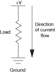
Ground is the place in a circuit with where the potential energy of the electrons is zero. Sometimes this point is connected to the actual ground, either through a grounded electrical circuit, water pipe, or some other method. Basically, any conductor that goes to the earth will do.
Electrical Energy Flow in a Circuit
When you start to add multiple components to a circuit, following the electrical energy can get a bit more complex. Following are some principles that explain how energy flows in a circuit.
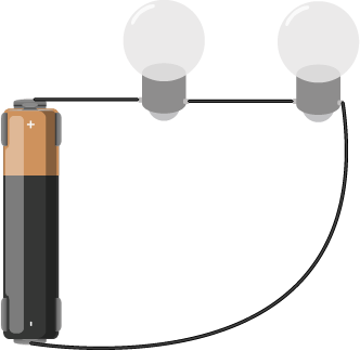
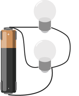
Electrical components can be arranged in a circuit so that the energy flows through one to the other, or they can be arranged so that the energy is split, flowing through both at the same time. When the energy flows from one to the other, the components are in series (Figure 10). When it flows through them at the same time, they are in parallel (Figure 11).
There are a few rules that explain how electrical energy moves through these circuits:
Current tends to follow the path of least resistance to the ground. So if it has a choice of two paths in a circuit, and one has less resistance, that’s the path it’ll take. Looking at the parallel circuit above, if one light bulb offered less resistance, then more of the current wold pass through that bulb.
In any given circuit, the total voltage around the path of the circuit is zero. Each component that offers a resistance lowers the voltage, and by the time you reach the end of the circuit loop, there will be no voltage left. In other words, all energy generated by the electrical power source in a circuit is converted to some other form of energy. Looking at the light bulbs in series above, if you were to measure the voltage on between the two contacts of each bulb, it would be less than the voltage between the contacts of the battery, but when you add up the voltages for all the bulbs, the sum would equal the voltage of the battery.
This explains why some components in a circuit get warm when you don’t expect them to. They are offering resistance to the energy in the circuit, and if they are not efficient at converting that energy into their desired form of energy, they convert it to heat.
The amount of current going into any point in a circuit is the same as the amount coming out of that point.
Let’s look in more detail at how the current and voltage changes when components are in series or in parallel:
When two components are in series, they are placed one after another, as shown in Figure 12:
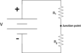
When resistors are in series, the voltage drops across each resistor, and the total resistance is equal to the sum of all the resistors:
Resistors in series:
Rtotal = R1 + R2 + R3…
In the above circuit, the current through both of the resistors is the same and the voltage drops across each resistor, and the total of all the voltage drops equals the voltage across the battery. The voltage between the junction point and the negative terminal of the battery (which is the ground of this circuit) is dependent on the ratio of the two resistors in series. If the resistors are equal in resistance value, then the voltage at the junction point is exactly half that of the battery’s total voltage.
When two components are in parallel, they are placed beside each other, as shown in Figure 13:
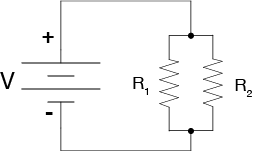
For resistors in parallel, the voltage across them is equal, but the current is divided between them. The divided current across the parallel resistors is equal to the total current. So I1 + I2 = Itotal. That means that
1/Rtotal = 1/R1 + 1/R2 + 1/R3…
If the resistors are equal in resistance value, then the current flowing through each of them is half that of the total current.
Though it’s sometimes useful to think about the mathematical relationships of parallel and series circuits, it’s often more useful to think about them in terms of practical effects: resistors divide voltage when in series, and divide amperage when in parallel.
When you’re ready to begin building circuits, read the Breadboard Setup Lab for a quick introduction to how to use a solderless breadboard. The Components Lab introduces many of the components you will use and the Electronics lab introduces you to how to measure electrical properties. You should also read the the switches lab, and watch this video about connections in schematics.