In this tutorial, you’ll learn how to control a high-current load with a transistor.
Introduction
Transistors are often used as electronic switches, to control loads which require high voltage and current from a lower voltage and current. The most common example you’ll see of this in a physical computing class is to use an output pin of a microcontroller to turn on a motor or other high current device. The output pins of a microcontroller can only produce a small amount of current and voltage. But when coupled with a transistor, they can control much more.
Microcontrollers aren’t the only integrated circuits that produce a low voltage and current on their output pins. There are many components that do this. You’ll see a whole range of so-called logic ICs that can’t produce very much current or voltage, but can produce a small change on their output pins that can be read as a data or control signal. The output voltage from devices is often referred to as a logic or a control voltage, as opposed to the supply or load voltage needed to control the high-current device. You can use transistors from circuits like these. For example, you might put a transistor on the output pin of a 555 timer IC (which produces a variable timing pulse), or a shift register IC (which allows you to produce multiple control signals in parallel) to control high current loads from those devices.
Things You’ll Need
Figures 1-12 are the parts you’ll need for this exercise.
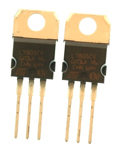
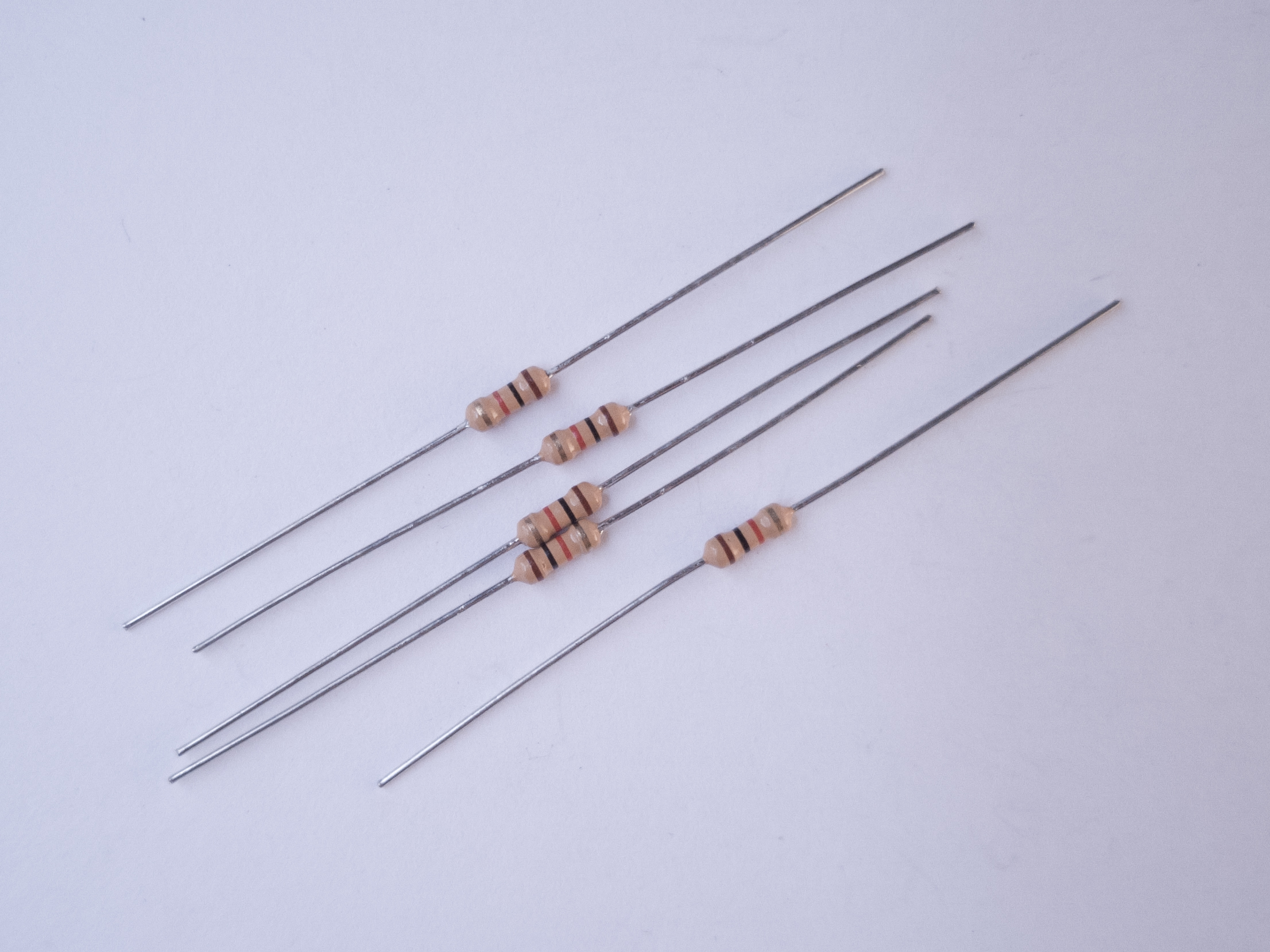
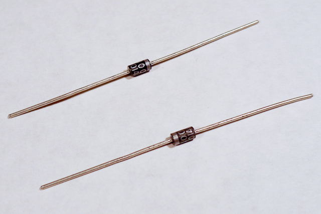
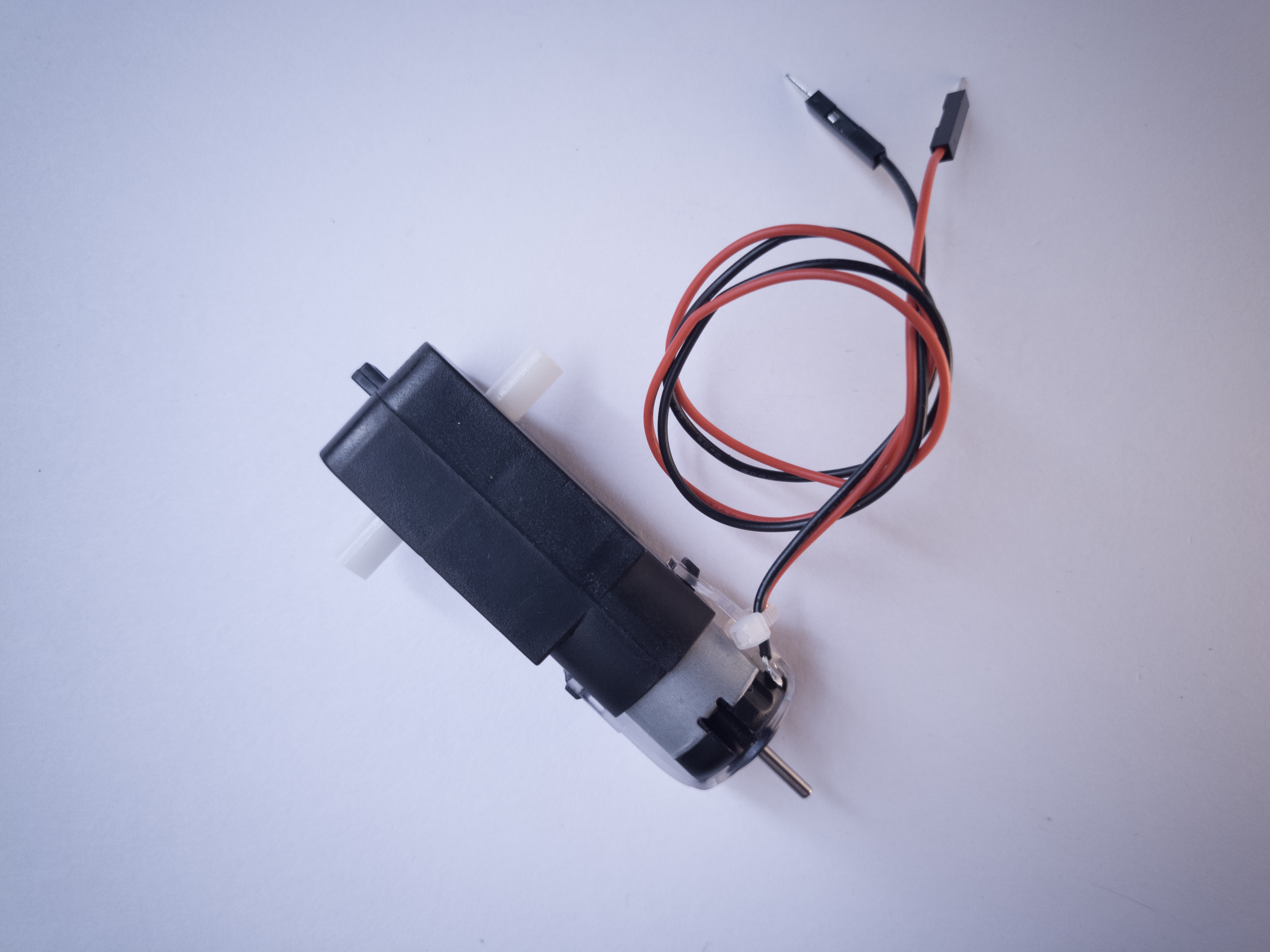
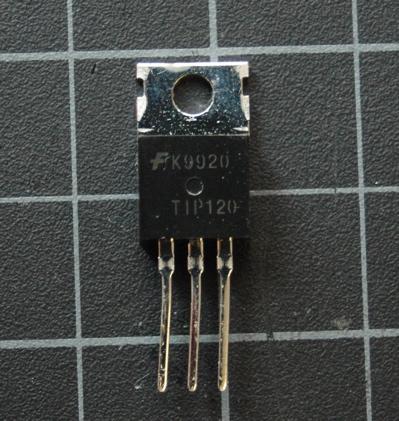
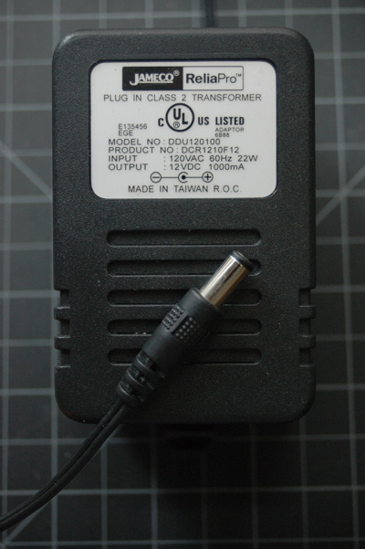
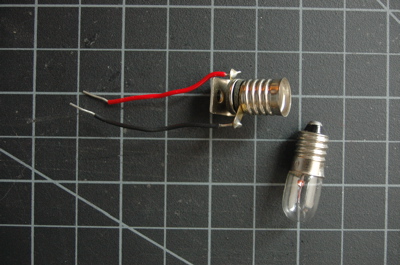
Figure 1. A short solderless breadboard.Figure 2. 22AWG solid core hookup wires. Figure 3. 5-volt voltage regulator, model 7805 Figure 4. Resistors. You’ll need 1-kilohm and 10-kilohm for thisFigure 5. Diodes. Shown here are 1N400x power diodes.Figure 6. DC motorFigure 7. TIP120 Transistor. You can also use a MOSFET, see belowFigure 8. PushbuttonsFigure 9. PotentiometerFigure 10. Force Sensing Resistor (FSR) or other variable resistorFigure 11. DC Power SupplyFigure 12. Small Incandescent lamp bulb or LED bulb and socket
Set Up the Breadboard
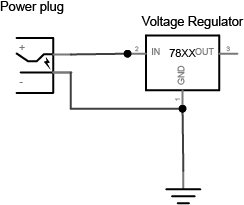
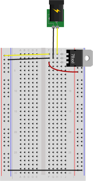
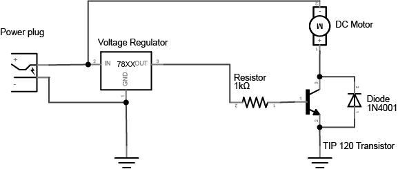
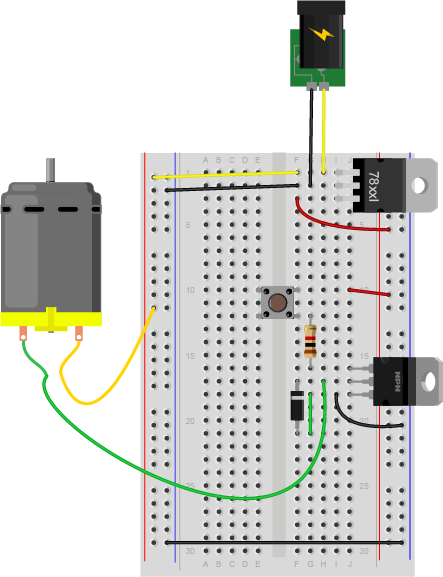
Connect a 7805 5V voltage regulator to your board, and power it from a 9-12V DC power supply. Connect the ground rows on the sides together. Don’t connect the two red rows on the side of the breadboard to each other, though. Wire the breadboard so that the right side of the board receives the 5V output from the regulator, but the left side gets 9-12V directly from your DC power supply. The 5V line is the 5-volt bus or logic supply and the 9-12V line is the high-voltage bus or load supply. The two ground lines are ground. Figure 13 shows the schematic drawing and Figure 14 shows the breadboard view of the circuit explained here.
Figure 14. Schematic drawing of a DC power jack connected to a 7805 5-volt voltage regulator.
Figure 14. DC voltage jack and 7805 voltage regulator on a breadboard. The regulator is supplying 5V and ground holes are supplying voltage to the rest of breadboard.
Add a Motor and Transistor
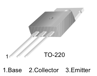
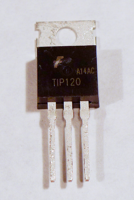
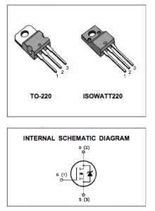
The transistor allows you to control a circuit that’s carrying higher current and voltage from the a lower voltage and current. It acts as an electronic switch. The one you’re using for this lab is an NPN-type transistor called a TIP120. The datasheet for it can be found here. It’s designed for switching high-current loads. It has three connections, the base, the collector, and the emitter as shown in Figure 15 and Figure 16. Attach high-current load (i.e. the motor or light) to its power source, and then to the collector of the transistor. Then connect the emitter of the transistor to ground. Then to control the motor, you apply voltage to the transistor’s base. When there’s at least a 0.7V difference between the base and the emitter, the transistor will “turn on” — in other words, it’ll allow voltage and current to flow from the collector to the emitter. When there’s no voltage difference between the base and the emitter, the transistor turns off, or stops the flow of electricity from collector to emitter.
Figure 15. The schematic symbol of an NPN transistor. B is the base, C is the collector, and E is the emitter.
Figure 16. Pinout drawing of a TIP-120 transistor. From left to right the legs are labelled 1. base, 2. collector, 3. emitter.
Using a MOSFET instead of a TIP120
Figure 17. FQP30N06L MOSFET transistor pin diagram and schematic symbol
You can also use an N-channel MOSFET transistor for this. The diagram and schematic symbols are shown above in Figure 17. The IRF520 and the FQP30N06L MOSFETs are similar in function, and have the same pin configuration as the TIP120, and perform similarly. They can handle more amperage and voltage, but are more sensitive to static electricity damage.
Connect a 1-kilohm resistor from the transistor’s base to another row of the breadboard. This resistor will limit the current to the base.
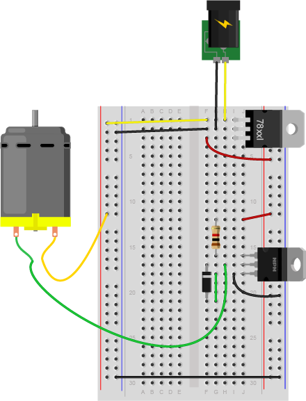
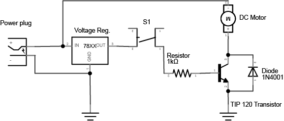
You also need to add a diode in parallel with the collector and emitter of the transistor, pointing away from ground as shown in Figure 18 and Figure 19. The diode to protects the transistor from back voltage generated when the motor shuts off, or if the motor is turned in the reverse direction. This is called a snubber diode, or protection diode. Related topics: Transistors, Relays, and Controlling High-Current Loads
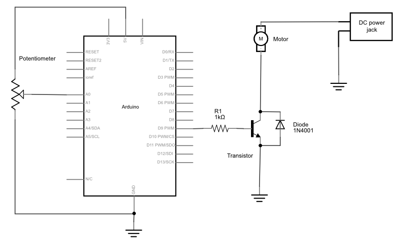
Figure 18. Schematic drawing of a transistor controlling a DC motor.
Figure 19. Breadboard view of a transistor controlling a DC motor.
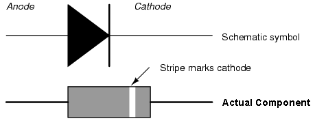
Be sure to add the diode to your circuit correctly. The silver band on the diode denotes the cathode which is the tip of the arrow in the schematic, as shown in Figure 20:
Figure 20. Schematic representation and physical representation of a diode.
This circuit assumes you’re using a 12V motor. If your motor requires a different voltage, make sure to use a power supply that’s appropriate. The TIP120 transistor can handle up to 30V across the collector and emitter, so make sure you’re not exceeding that. Connect the ground of the motor’s supply to the ground of your microcontroller circuit, though, or the circuit won’t work properly.
Add a Switch to Control the Transistor
To turn on the transistor, you need a voltage difference between the base and the emitter of at least 0.7V. Since the emitter is attached to ground, that means any voltage over 0.7V applied to the base will turn the transistor on.
Connect a wire from the 5-volt bus of the board (also called the regulated voltage bus) to the other end of the 1 kilohm resistor as shown above and you should see the motor turn on.
Of course, it’s inconvenient to connect and disconnect a wire like this, so use a switch instead.
Remove the red wire connecting the resistor to 5 volts and connect one side of a pushbutton or switch to the 5-volt bus, and the other side to the 1K resistor. Figure 21 shows the schematic drawing and Figure 22 shows the breadboard view of the circuit.
Figure 21. Schematic drawing of a transistor controlling a DC motor, with a pushbutton to turn it on and off.
Figure 22. Breadboard drawing of a transistor controlling a DC motor with a pushbutton.
Change the Switch for a Potentiometer
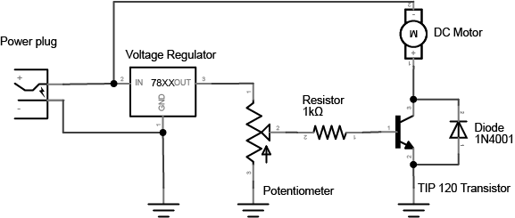
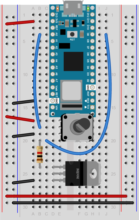
The voltage on the base of the transistor doesn’t have to be controlled by a switch. You can use a potentiometer, connected as a voltage divider, to produce a changing control voltage for the transistor’s base. Figure 23 shows the schematic drawing and Figure 24 shows the breadboard view of the circuit. Related video: Connecting the potentiometer
Figure 23. Schematic drawing of a transistor controlling a DC motor, with a potentiometer to change the speed.
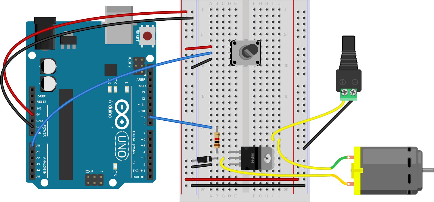
Figure 24. Breadboard drawing of a transistor controlling a DC motor with a potentiometer.
When you turn the potentiometer, you’re producing a varying voltage on the wiper pin. That means you’re changing the voltage on the base of the transistor. Yet the motor doesn’t change its speed. It only turns on or off. When the voltage on the potentiometer’s wiper pin reaches 0.6V, the transistor will turn on. When it’s below 0.6V, the transistor will turn off. The transistor is acting like a switch, not a variable supply. If you want to vary the motor’s speed using a transistor, you need to turn the transistor on and off very fast, and change the ratio of on time to off time. This is called pulse width modulation. You’ll learn more about it in these notes on analog output from a microcontroller and see it in action in the analog lab.
Change the Potentiometer for a Voltage Divider
If you’ve understood everything so far and managed to get it to work, here’s where it gets really fun. Imaging you have a variable resistor and you want the motor to turn on when the variable resistor passes a particular threshold. For example, maybe you want to turn on the motor when a temperature changes on a thermistor (temperature sensitive resistor), or when a weight is placed on a force-sensing resistor. To make this happen, change your control circuit to include a variable resistor as shown in Figure 25 and Figure 26.
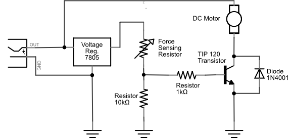
Figure 25. Schematic drawing of a transistor controlling a DC motor, with a potentiometer to change the speed.
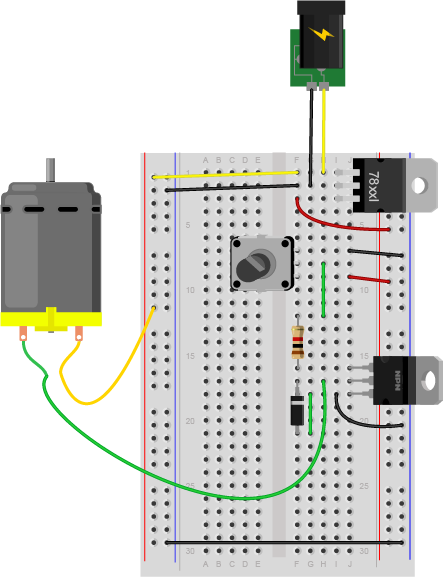
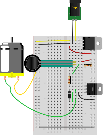
Figure 26. Breadboard drawing of a transistor controlling a DC motor with a voltage divider.
Using a Voltage Divider to Control a Transistor
Extra credit: See if you can work out the correct resistor value for the fixed resistor of the voltage divider that will produce just the right voltage to turn the motor on when you turn on your room’s lights, and off when you turn them off.
Whoa, that blew my mind. How do I do that?
You know you need 0.7V to turn the transistor on, and less than that to turn it off. You know how to measure the resistance of a variable resistor. So find the resistance of your variable resistor with the lights on and with the lights off, and calculate what fixed resistor will give you 0.6V. The input to your voltage divider here is 5V. That means you want 4.3 volts across the variable resistor. You know that the output voltage is proportional to the ratio of the two resistors. And you know that the current running between them is the same, because they are in series. So: Voltage = current * resistance 4.3V = current * photocell resistance therefore, current = 4.3V / variable resistor resistance Then apply this to the fixed resistor: 0.7V = current * fixed resistor resistance therefore, fixed resistor resistance = current / 0.7V or: fixed resistor resistance = (4.3V / variable resistor resistance) / 0.7V
If you’re using a force sensing resistor as your variable resistor (an Interlink model 402 is shown here), you’ll probably find that they’re very sensitive. They tend to be greater than 10 megohms resistance when no force is on them and near zero when pressed. See the graph on page 3 of the datasheet for the voltage output for various fixed resistor values.
Connect a lamp instead
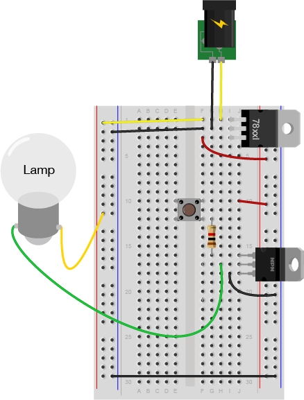
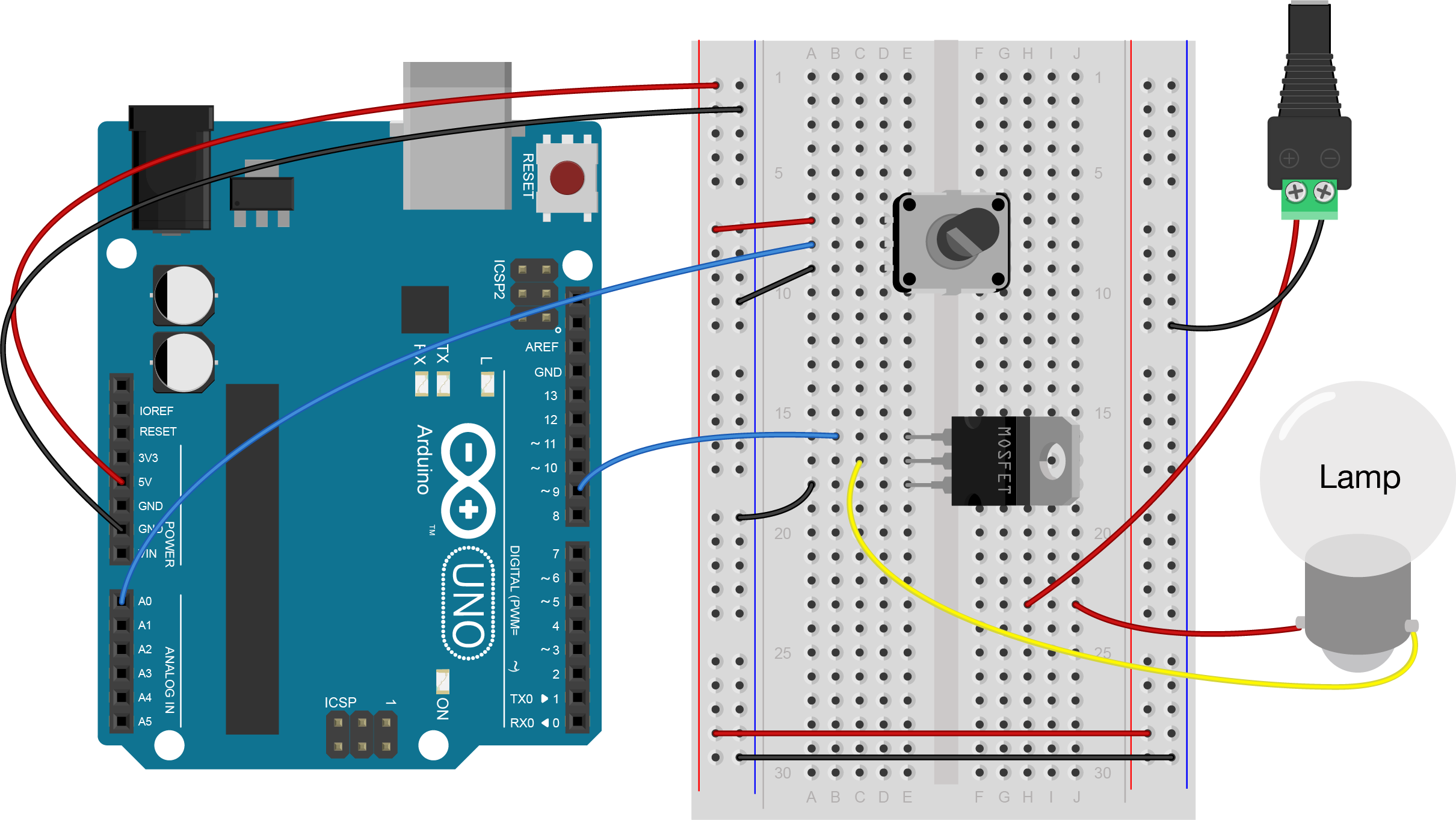
You could also control a lamp using a transistor. Figure 27 shows the schematic drawing and Figure 28 shows the breadboard view of the circuit. Like the motor, the lamp circuit below assumes a 12V lamp. Change your power supply accordingly if you’re using a different lamp. In the lamp circuit, the protection diode is not needed, since there’s no way for the polarity to get reversed in this circuit:
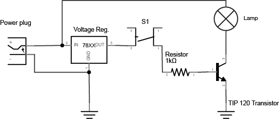
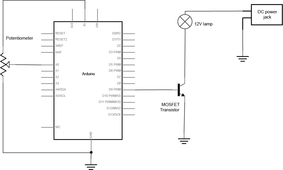
Figure 27. Schematic drawing of a transistor controlling an incandescent lamp with a pushbutton.
Figure 28. Breadboard drawing of a transistor controlling an incandescent lamp with a pushbutton.
Conclusion
A motor controlled like this can only be turned in one direction. To be able to reverse the direction of the motor, an H-bridge circuit is required. For more on controlling DC motors with H-bridges, see the DC Motor Control lab.
In this tutorial, you’ll learn how to control a DC motor’s direction using a DC Motor Driver.
Introduction
In this tutorial, you’ll learn how to control a DC motor’s direction using a DC Motor Driver.
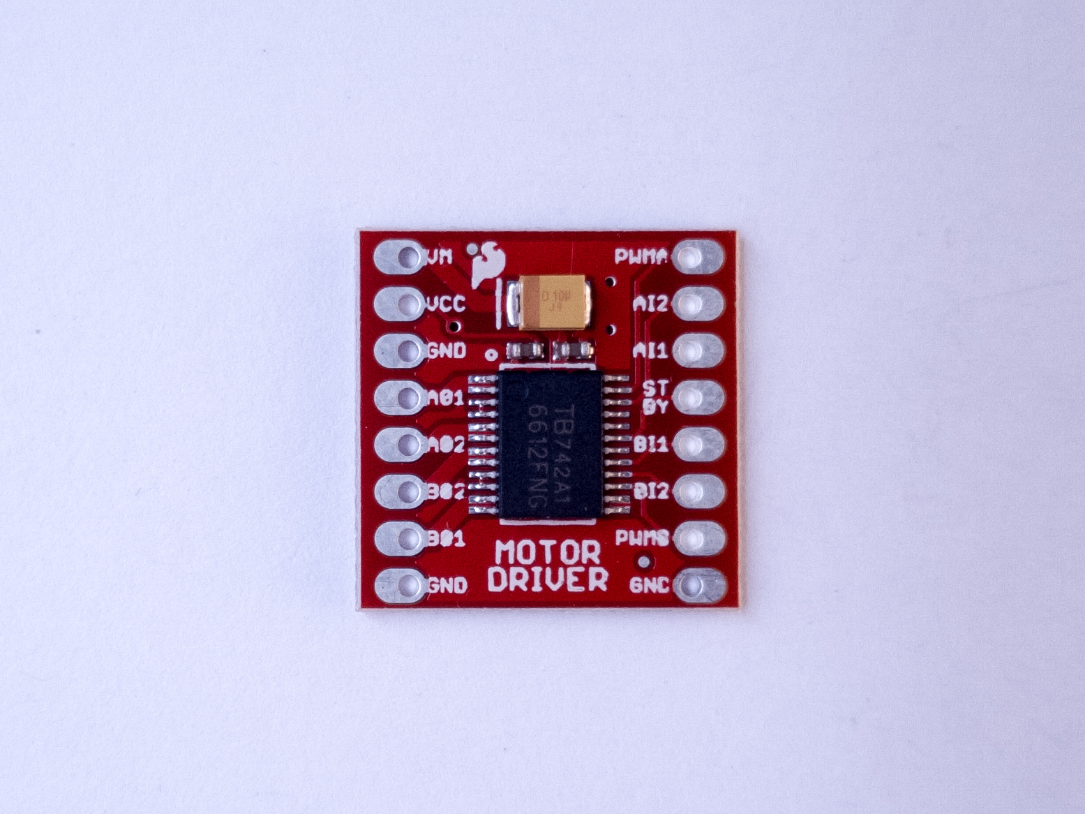
To reverse a DC motor, you need to be able to reverse the direction of the current in the motor. The classic way to do this is using an H-bridge circuit. Though most motor driver chips these days are not in fact H-bridge circuits, the term still persists. This tutorial uses a Toshiba motor driver, the TB6612FNG, which can actually drive two DC motors. Both Sparkfun, Adafruit, and Pololu make breakout boards for the motor driver, though the Sparkfun one is shown in the examples below.
At the end of the lab, an alternative motor driver, the L9110H, is shown. This motor driver can only drive one motor at a time, unlike the TB6612FNG, but it’s more inexpensive than the TB6612FNG.
A solderless breadboard with two rows of holes along each side.
Motor Driver (H-bridge), model TB6612FNG
DC Gearmotor
10-kilohm resistors. These ones are 5-band resistors
Pushbuttons
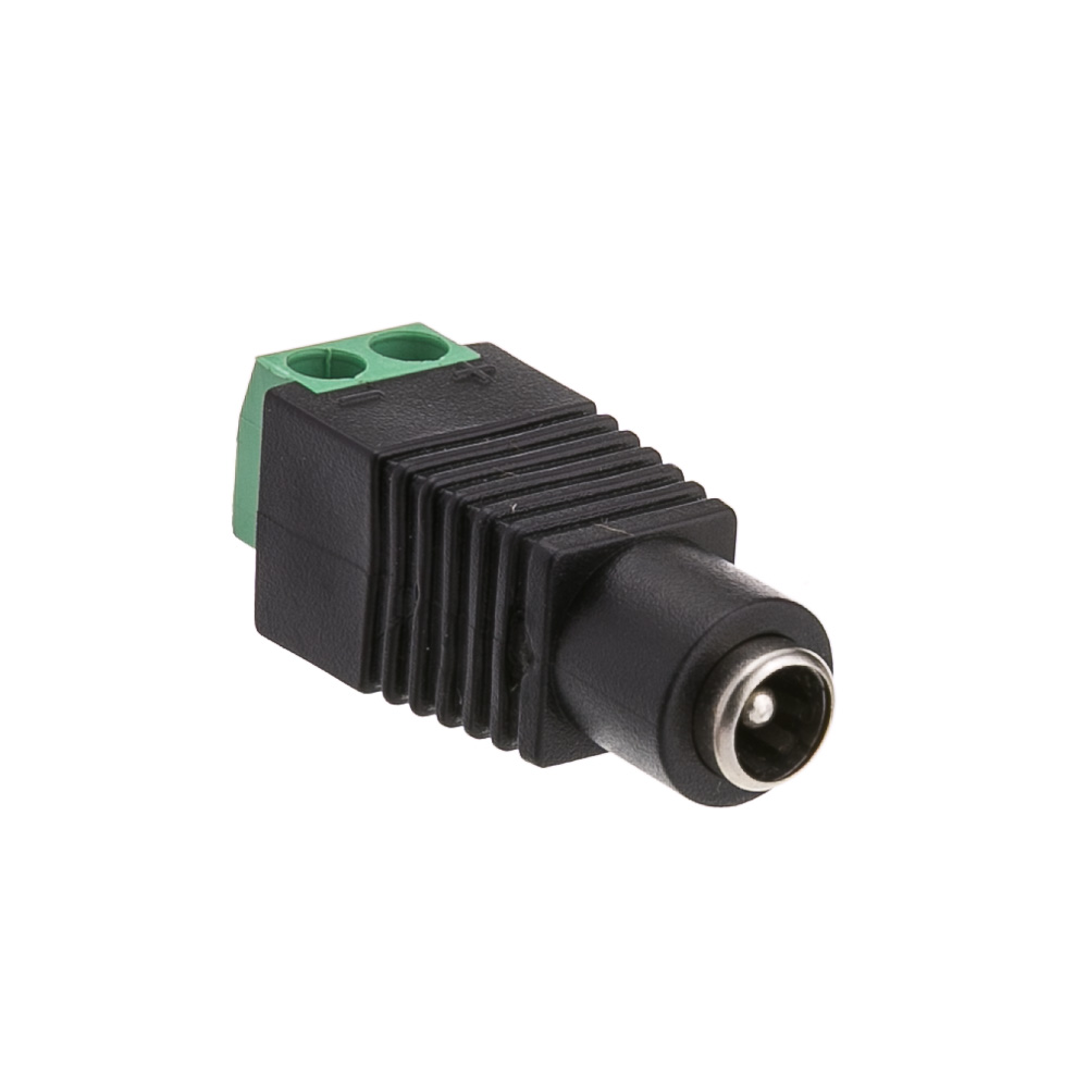
A DC Power Jack
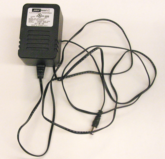
DC Power Supply
Figures 1-9. The parts you’ll need for this exercise. Click on any image for a larger view.
Prepare the breadboard
Connect power and ground on the breadboard to power and ground from the microcontroller. On the Arduino module, use the 5V or 3.3V (depending on your model) and any of the ground connections, as shown in Figures 10 and 11.
Figure 10. Breadboard drawing of an Arduino Uno on the left connected to a solderless breadboard on the right
Figure 10 shows an Arduino Uno on the left connected to a solderless breadboard, right. The Uno’s 5V output hole is connected to the red column of holes on the far left side of the breadboard. The Uno’s ground hole is connected to the blue column on the left of the board. The red and blue columns on the left of the breadboard are connected to the red and blue columns on the right side of the breadboard with red and black wires, respectively. These columns on the side of a breadboard are commonly called the buses. The red line is the voltage bus, and the black or blue line is the ground bus.
Figure 11. Breadboard view of an Arduino Nano mounted on a solderless breadboard.
As shown in Figure 11, the Nano is mounted at the top of the breadboard, straddling the center divide, with its USB connector facing up. The top pins of the Nano are in row 1 of the breadboard.
The Nano, like all Dual-Inline Package (DIP) modules, has its physical pins numbered in a U shape, from top left to bottom left, to bottom right to top right. The Nano’s 3.3V pin (physical pin 2) is connected to the left side red column of the breadboard. The Nano’s GND pin (physical pin 14) is connected to the left side black column. These columns on the side of a breadboard are commonly called the buses. The red line is the voltage bus, and the black or blue line is the ground bus. The blue columns (ground buses) are connected together at the bottom of the breadboard with a black wire. The red columns (voltage buses) are connected together at the bottom of the breadboard with a red wire.
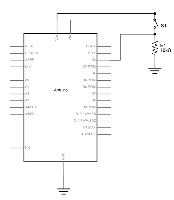
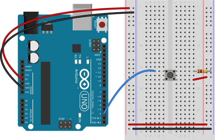
Connect a pushbutton to digital input 2 on the Arduino. Figure 12 shows the schematic, Figure 13 shows the breadboard view for the Uno, and Figure 14 the breadboard view for the Nano.
Figure 12. Schematic Diagram of a pushbutton attached to an Arduino as a digital input. A 10-kilohm resistor connects from the pushbutton to ground.
Figure 13. Breadboard view of a pushbutton attached to an Arduino Uno. The Arduino is connected to a breadboard as described in the image above. A pushbutton is mounted in across the center section of the breadboard. A red wire connects from the left side voltage bus to the lower right pin of the pushbutton. A blue wire connects the upper left pin of the pushbutton to digital pin 2 on the Arduino. A 10-kilohm resistor connects the upper right pin of the pushbutton to the ground bus on the left side of the board.
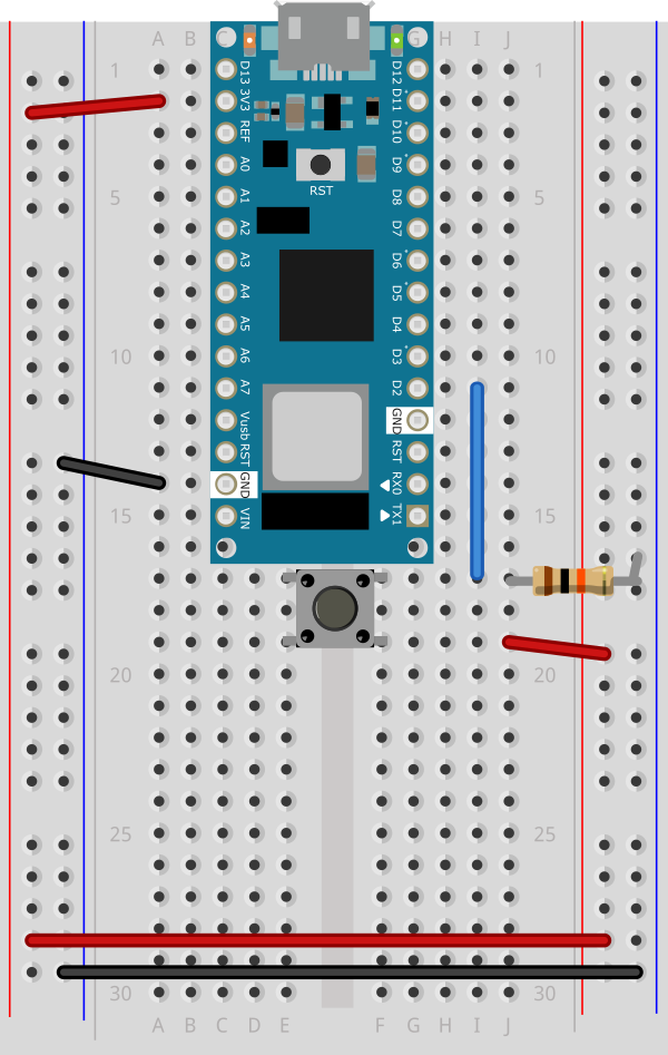
Figure 14. Breadboard view of a pushbutton attached to an Arduino Nano 33 IoT.
As shown in Figure 14, the Nano is mounted across the center divide of the breadboard with the USB connector pointing up. A pushbutton is mounted in across the center section of the breadboard. A red wire connects from the left side voltage bus to the lower right pin of the pushbutton. A blue wire connects the upper left pin of the pushbutton to digital pin 2 on the Arduino. A 10-kilohm resistor connects the upper right pin of the pushbutton to the ground bus on the left side of the board.
Find a motor
Find yourself a DC motor that runs on low DC voltage within the range of 3 – 15V. This one works well for this, or this one or this one. Discarded toys and printers can be good sources of these also. The ITP free store is almost always a goldmine for discarded motors and fans. Asking classmates and second years is another good approach.
Solder leads to the motor’s terminals. The motor’s direction depends on the polarity, so it’s helpful to use different colors so you know which way the motor will turn when you hook it up.
Optional: Consider testing your motor with a bench power supply from the equipment room. Ask a teacher or resident if you need help setting one up. Begin by adjusting the voltage on the bench power supply and observe its effects. Take note of its speed at different voltages without dipping to low or too high.
Safety Warning: Running a motor at a voltage much lower or much higher than what it’s rated for could potentially damage or permanently destroy your motor. When the motor doesn’t spin, the voltage is too low. When the motor runs hot, or sounds like it’s straining, the voltage is too high.
Powering Your Motor
If your motor can run on 5V (if you’re using an Uno) or 3.3V (if using a Nano 33 IoT ) and less than 500mA, you can use the Arduino’s USB voltage. Most motors require a higher voltage and higher current draw than this, however, so you will need an external power supply. You can use any DC power supply or battery up to 15V with this motor driver as long as your motor can run at that voltage, and as long as the supply can supply as much current as your motor needs. However you choose to power this circuit, make sure the power source is compatible with your motor. For example, don’t use a 9V battery for a 3V motor.
The diagrams below show how to power the motor from an external power supply. To power directly from the Arduino’s Vcc, connect the VMOT pin of the motor driver to the Vcc pin on the Arduino (5V on Uno, 3.3V on Nano)
The TB6612FNG can handle a motor supply voltage up to 15V, and it operates on a logic voltage of 2.7–5.5V. It can control an output current of 1.2A. It has two motor driver circuits, each with two logic inputs and two motor outputs. Each motor driver has a PWM input, because they are expected to be used for speed control for the motor by pulse width modulating this pin. There’s also a Standby pin that you have to connect to voltage through a 10-kilohm pullup resistor to activate the motor driver circuits.
The motor driver has the following pins. The pin numbers shown here are for the Sparkfun breakout board. The order of the pins will be different for the Adafruit and Pololu boards. The Pins are numbered here in a DIP fashion, in a U-shape from top left to bottom left, then bottom right to top right.
VMOT – motor voltage supply input, up to 15V.
Vcc – logic voltage supply input, 2.7-5.5V
Gnd – ground
AO1 – A channel output 1. This is the first motor terminal for the first motor driver
AO2 – A channel output 2. This is the second motor terminal for the first motor driver
BO2 – B channel output 2. This is the second motor terminal for the second motor driver
BO1 – B channel output 1. This is the first motor terminal for the second motor driver
Gnd – ground
Gnd – ground
PWMB – B Channel PWM Enable. This pin controls the speed for channel B, regardless of the channel’s direction
BI2 – B channel input 2. This controls B channel output 2. To control that pin, take this pin HIGH or LOW.
BI1 – B channel input 1. This controls B channel output 1. To control that pin, take this pin HIGH or LOW.
Stdby – enables both drivers when you take it HIGH and disables them when you take it LOW
AI1 – A channel input 1. This controls A channel output 1. To control that pin, take this pin HIGH or LOW.
AI2 – A channel input 2. This controls A channel output 2. To control that pin, take this pin HIGH or LOW.
PWMA – A Channel PWM Enable. This pin controls the speed for channel A, regardless of the channel’s direction
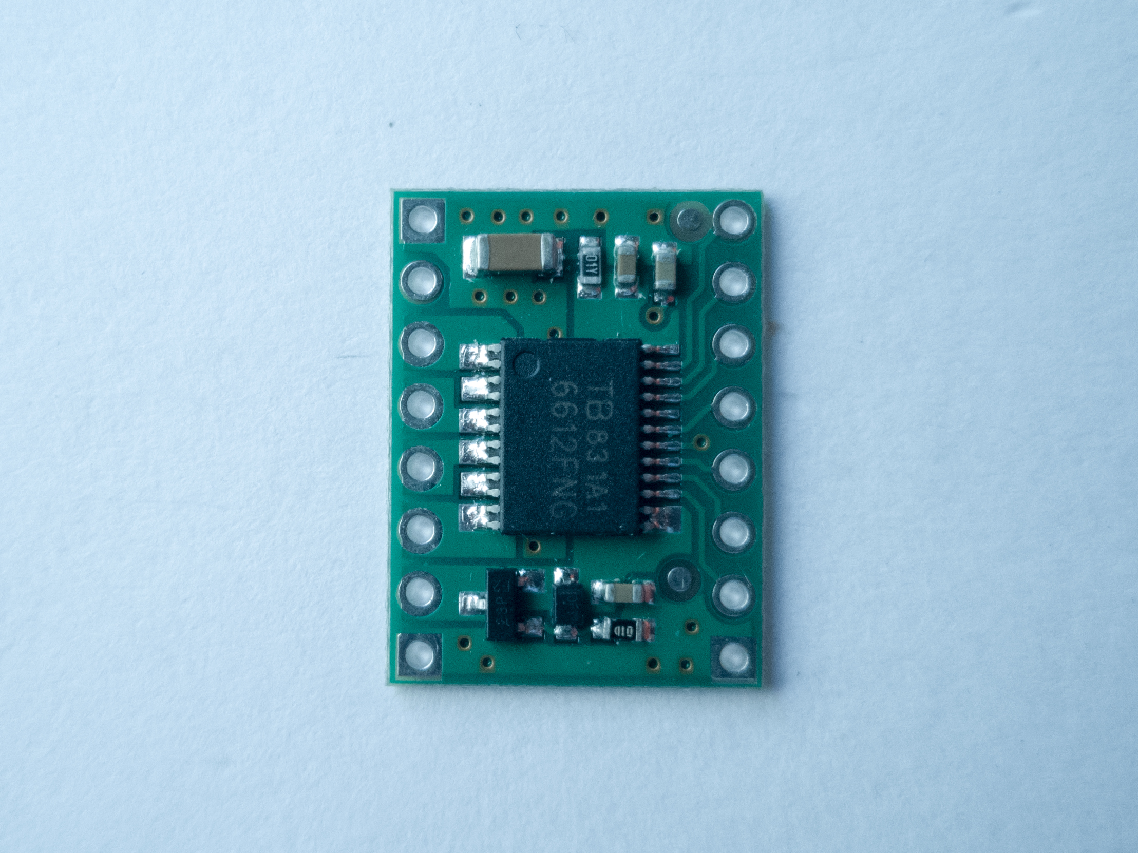
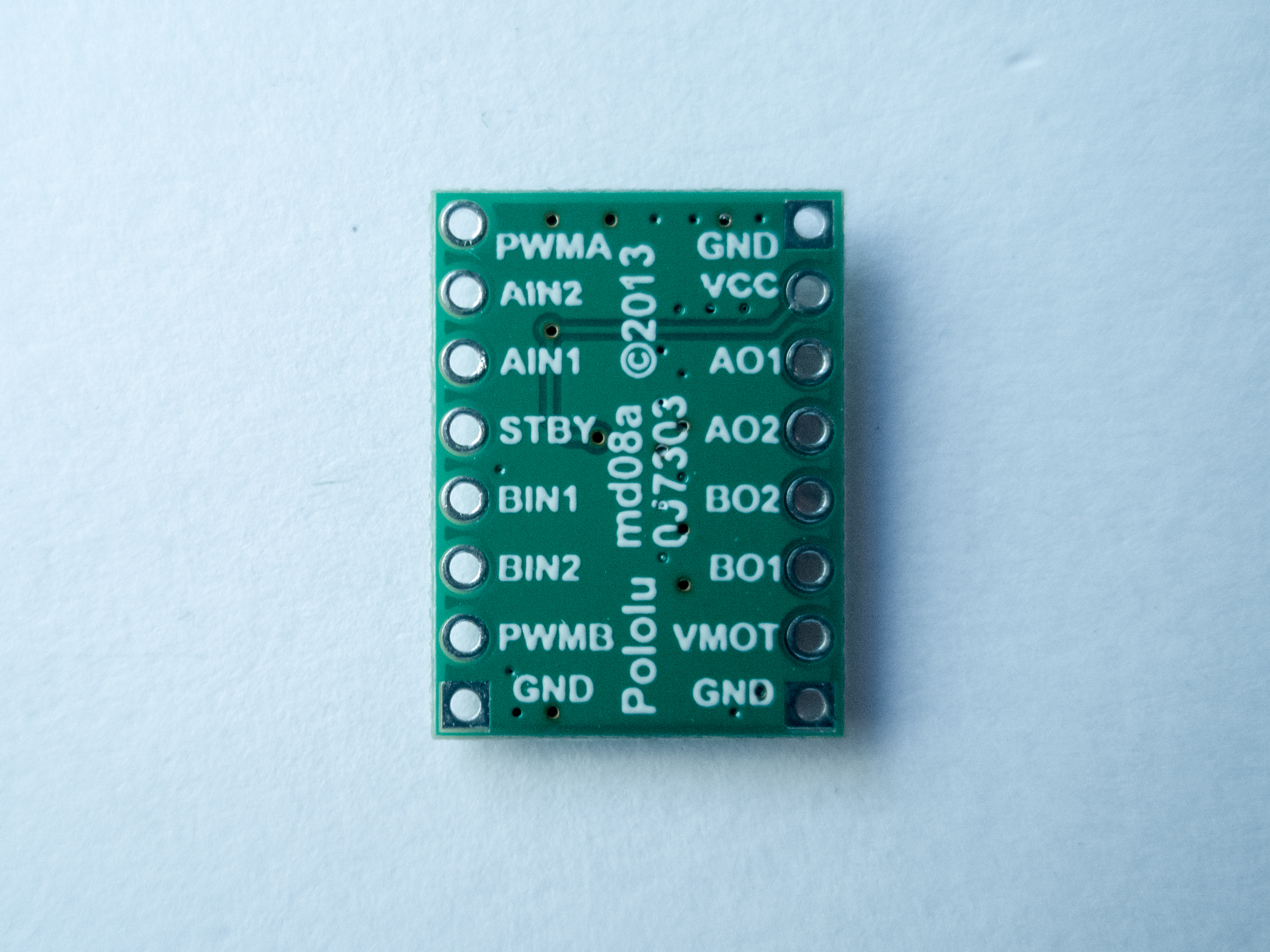
Figure 15 shows the Sparkfun board, and Figures 16 and 17 show the Pololu board front and back. The Pololu board is labeled on the back. You can see that both boards have the same pins, even though the layouts are different.
Figure 15. Motor Driver (H-bridge), model TB6612FNG
Figure 16. Pololu’s TB6612FNG Dual Motor Driver Carrier (front view of the board)
Figure 17. Pololu’s TB6612FNG Dual Motor Driver Carrier (back of the board)
You can change the direction and speed of the motor using the motor driver. The truth table below shows how the motor driver works.
AI1
AI2
PWMA
Effect
H
L
H
Motor turns one direction
L
H
H
Motor turns the other direction
L
L
–
Motor stop
H
H
–
Motor stop
–
–
L
Motor stop
For this lab, the PWMA pin connects to a digital pin on your Arduino so you can send it either HIGH or LOW and turn the motor ON or OFF, or pulse width modulate it to control the speed. The motor logic pins are also connected to designated digital pins on your Arduino so you can set them HIGH and LOW to turn the motor in one direction, or LOW and HIGH to turn it in the other direction. The motor supply voltage connects to the voltage source for the motor, which is usually an external power supply.
Connect the motor to the Driver
Connect the motor to the driver as shown in Figures 18 – 20. Figure 18 shows the schematic, Figure 19 shows the breadboard view for an Uno, and Figure 20 shows the breadboard view for a Nano.
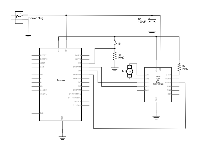
Figure 18. Schematic diagram of an Arduino connected to a motor driver to control a DC motor. The Arduino and switch are connected as described in the drawing above. A motor driver has been added, and is connected as follows: PWMA is connected to the Arduino’s digital pin 5. AIN1 is connected to digital pin 4. AIN2 is connected to digital pin 3 on the Arduino. AO1 and AO2 are connected to the DC motor’s two connections. The ground pins are connected to ground. VMOT is connected to the positive terminal of a DC power source for Arduino and the motor. The power source’s negative terminal is connected to ground. The motor driver’s Vcc pin is connected to the Arduino’s voltage output (5V or 3.3V depending on your model). The Standby pin is connected to voltage through a 10-kilohm resistor. The rest of the driver pins are unconnected.
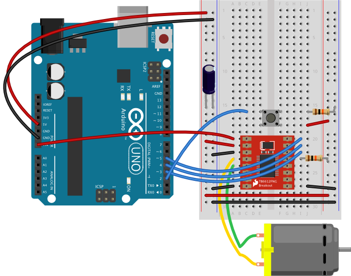
Figure 19. Breadboard drawing of an Arduino connected to a motor driver to control a DC motor. The Arduino and switch are connected as described in the breadboard drawing above. A motor driver has been added, straddling the center of the breadboard. PWMA is connected to the Arduino’s digital pin 5. AIN1 is connected to digital pin 4. AIN2 is connected to digital pin 3 on the Arduino. AO1 and AO2 are connected to the DC motor’s two connections. The ground pins are connected to ground. VMOT is connected to the VIN terminal the Arduino, and the Arduino should be powered through its DC power jack. The power source’s negative terminal is connected to ground. The motor driver’s Vcc pin is connected to the Arduino’s voltage output (5V for the Uno). The Standby pin is connected to voltage through a 10-kilohm resistor. The rest of the driver pins are unconnected. A 100-microfarad capacitor has been added connecting the voltage and ground buses close to the motor driver, to act as a decoupling capacitor.
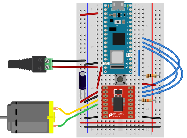
Figure 20. Breadboard drawing of an Arduino Nano connected to a motor driver to control a DC motor. The Arduino and switch are connected as described in the breadboard drawing above. A DC power jack has been added, connected to the Nano’s ground and Vin pin (pins 14 and 15, respectively). A motor driver has been added, straddling the center of the breadboard. PWMA is connected to the Arduino’s digital pin 5. AIN1 is connected to digital pin 4. AIN2 is connected to digital pin 3 on the Arduino. AO1 and AO2 are connected to the DC motor’s two connections. The ground pins are connected to ground. VMOT is connected to the Nano’s Vin pin, which is connected to the positive terminal of the DC power source for the motor. The power source’s negative terminal is connected to ground. The motor driver’s Vcc pin is connected to the Arduino’s voltage output (3.3V). The Standby pin is connected to voltage through a 10-kilohm resistor. The rest of the driver pins are unconnected. A 100-microfarad capacitor has been added connecting the voltage and ground buses close to the motor driver, to act as a decoupling capacitor.
Note on decoupling capacitors
If you find that your microcontroller is resetting whenever the motor turns on, add a capacitor across power and ground close to the motor. The capacitor will smooth out the voltage dips that occur when the motor turns on. This use of a capacitor is called a decoupling capacitor. Usually a 10 – 100uF capacitor will work. The larger the cap, the more charge it can hold, but the longer it will take to release its charge.
Program the microcontroller
Program the microcontroller to run the motor through the driver. First set up constants for the switch pin, the two motor driver pins, and the PWM enable pin of the motor driver. Use pin 5, one of the pins that can produce a PWM signal using analogWrite(), for the PWM enable pin.
const int switchPin = 2;    // switch input
const int motor1Pin = 3;    // Motor driver leg 1 (pin 3, AIN1)
const int motor2Pin = 4;    // Motor driver leg 2 (pin 4, AIN2)
const int pwmPin = 5;       // Motor driver PWM pin
In the setup(), set all the pins for the motor driver as outputs, and the pin for the switch as an input. Then set the PWM enable pin high so the driver can turn the motor on.
void setup() {
    // set the switch as an input:
    pinMode(switchPin, INPUT);

    // set all the other pins you're using as outputs:
    pinMode(motor1Pin, OUTPUT);
    pinMode(motor2Pin, OUTPUT);
    pinMode(pwmPin, OUTPUT);

    // set PWM enable pin high so that motor can turn on:
    digitalWrite(pwmPin, HIGH);
  }
In the main loop() read the switch. If it’s high, turn the motor one way by taking one motor driver pin high and the other low. If the switch is low, reverse the direction by reversing the states of the two pins.
void loop() {
    // if the switch is high, motor will turn on one direction:
    if (digitalRead(switchPin) == HIGH) {
      digitalWrite(motor1Pin, LOW);   // set leg 1 of the motor driver low
      digitalWrite(motor2Pin, HIGH);  // set leg 2 of the motor driver high
    }
    // if the switch is low, motor will turn in the other direction:
    else {
      digitalWrite(motor1Pin, HIGH);  // set leg 1 of the motor driver high
      digitalWrite(motor2Pin, LOW);   // set leg 2 of the motor driver low
    }
  }
Once you’ve seen this code working, try modifying the speed of the motor using the analogWrite() function, as explained in the Analog Lab. Use analogWrite() on the PWM enable pin of the motor, and see what happens as you change the value of the analogWrite().
An Alternative Motor Driver
If you don’t have a TB6612FNG motor driver, or if you want something simpler and less expensive, the L9110H driver will also control a DC motor’s direction and speed. It can handle and input voltage of 2.5V-12V at 800mA of current. It can drive only one motor, unlike the TB6612FNG, and it can’t control stepper motors like that driver can. But it is inexpensive.
THe L9110H comes in an 8-pin DIP package. There are two inputs, labeled the A and B channels, and they are connected to two outputs, also labeled A and B. Your motor connects to the outputs and your control pins connect to the inputs. Vcc connects to the motor supply and GND connects to ground. Its pins, numbered from top left in a U shape as usual, are as follows:
OA – output for the A channel
Vcc – motor supply voltage
Vcc – motor supply voltage
OB output for the B channel
GND – ground
IA – input for the A channel
IB – input for the B channel
GND – ground
Figure 21 shows the schematic, and Figures 22 and 23 show it connected to an Uno and a Nano 33 IoT, respectively.
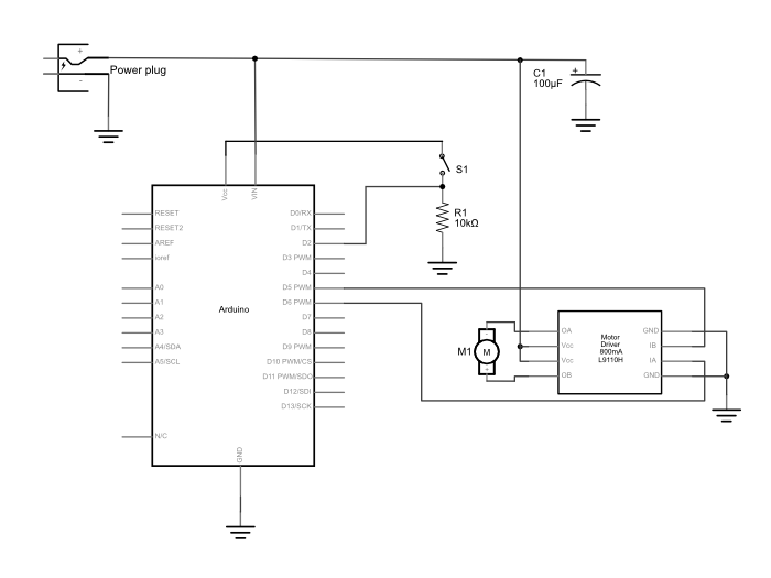
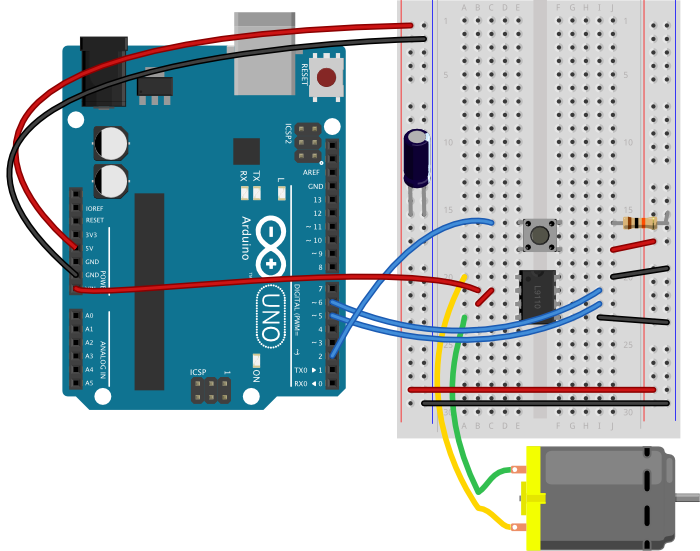
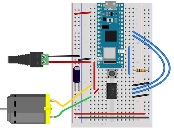
Figure 21. Schematic view of an L9110H H-bridge motor driver connected to an Arduino. A pushbutton is connected to pin 2 of the Arduino as shown in the circuits above. An external DC power supply is connected to the Arduino and the motor as shown in the circuits above as well, along with a 100-microfarad decoupling capacitor. A DC motor is connected to pins OA and OB of the H-bridge. Pins Vcc are both connected to the DC power supply and pins GND are connected to ground. Pin IA is connected to pin 5 of the Arduino, and pin IB is connected to pin 6 of the Arduino. Figure 22. Breadboard view of an L9110H H-bridge motor driver connected to an Arduino Uno. A pushbutton is connected to pin 2 of the Arduino as shown in the circuits above. The L9110H straddles the center divide of the breadboard with pins 1 and 8 facing the top of the diagram. The Arduino should be powered through its DC power jack. The Vin pin of the Arduino connects to the L9110H’s Vcc pins (physical pins 2 and 3). The motor is connected to the L9110H’s OA and OB pins (physical pins 1 and 4). A 100-microfarad decoupling capacitor is connected to the voltage and ground buses on the breadboard. Pins GND (physical pins 5 and 8) are connected to ground. Pin IA (physical pin 6) is connected to pin 5 of the Arduino, and pin IB (physical pin 6) is connected to pin 6 of the Arduino.Figure 23. Breadboard drawing of an Arduino Nano connected to a L9110H H-bridge motor driver to control a DC motor. The Arduino and switch are connected as described in the breadboard drawing above. A DC power jack has been added, connected to the Nano’s ground and Vin pin (pins 14 and 15, respectively). The L9110H straddles the center divide of the breadboard with pins 1 and 8 facing the top of the diagram. The Vin pin of the Arduino connects to the L9110H’s Vcc pins (physical pins 2 and 3). The motor is connected to the L9110H’s OA and OB pins (physical pins 1 and 4). A 100-microfarad decoupling capacitor is connected to the voltage and ground buses on the breadboard. THe L9110H’s ins GND (physical pins 5 and 8) are connected to ground. Pin IA (physical pin 6) is connected to pin 5 of the Nano, and pin IB (physical pin 6) is connected to pin 6 of the Nano.
To control the motor, you take one input high and the other low, just like with the previous motor driver. Since this driver has no PWM pin, you have to pulsewidth modulate the high input to manage speed control, though.
The program below controls the L9110H, setting the speed to about half the maximum whenever you push the button. To make a variable speed you could add a potentiometer and change the value of the speed variable using the potentiometer.
const int switchPin = 2;  // pushbutton input
const int motor1Pin = 5;  // H-bridge leg 1 (pin 6, 1A)
const int motor2Pin = 6;  // H-bridge leg 2 (pin 7, 2A)

// speed of the motor (0-255):
int speed = 127;

void setup() {
  // set the pushbutton as an input:
  pinMode(switchPin, INPUT);

  // set all the other pins you're using as outputs:
  pinMode(motor1Pin, OUTPUT);
  pinMode(motor2Pin, OUTPUT);
}

void loop() {
  // if the pushbutton is high, motor will turn on one direction:
  if (digitalRead(switchPin) == HIGH) {
    // set leg 1 of the H-bridge low:
    digitalWrite(motor1Pin, LOW);
    // set leg 2 of the H-bridge high:
    analogWrite(motor2Pin, speed);
  }
  // if the pushbutton is low, motor will turn in the other direction:
  else {
    // set leg 1 of the H-bridge high:
    digitalWrite(motor1Pin, speed);
    // set leg 2 of the H-bridge low:
    digitalWrite(motor2Pin, LOW);
  }
}
Get creative
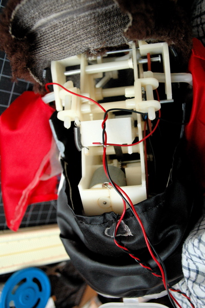
Motors can be used to make things move, vibrate, rise, fall, roll, creep, or whatever you can think of, in response to user input from a digital input device (switch, floor sensor, tripwire, etc). Look inside moving toys, you’ll find a number of excellent motors and gears you can re-purpose. See the innards of a cymbal monkey below as an example. Perhaps you can re-design the user interface to a toy, using the microcontroller to mediate between new sensors on the toy and the motors of the toy.
If you used a motor in this lab, consider any toys you have that have a motor you could take control over. Charley Chimp™ has a motor that’s easy to control from an Arduino, for example.
Figure 21. The guts of a Charley Chimp™ cymbal-playing monkey.
In this tutorial, you’ll learn how to control a high-current DC load such as a DC motor or an incandescent light from a microcontroller.
Introduction
In this tutorial, you’ll learn how to control a high-current DC load such as a DC motor or an incandescent light from a microcontroller. Microcontrollers can only output a very small amount of current from their output pins. These pins are meant to send control signals, not to act as power supplies. The most common way to control another direct current device from a microcontroller is to use a transistor. Transistors allow you to control the flow of a high-current circuit from a low-current source.
Safety Warning: This tutorial shows you how to control high-current loads. This comes with a higher danger of injury from electricity than the earlier tutorials. Please be careful and double-check your wiring before plugging anything in, and never change your wiring while your circuit is powered.
Things You’ll Need
Arduino Nano 33 IoTFlexible jumper wires. These wires are quick for breadboard prototyping, but can get messy when you have lots of them on a board.A solderless breadboard with two rows of holes along each side. The . board is turned sideways so that the side rows are on top and bottom in this view. There are no components mounted on the board. Gearmotor. Any DC motor in the 3-15V DC range will work in with this circuit, though 4-6V is an ideal range.A DC Power JackDC Power Supply to match your motor. If your motor is a 4-6V motor, you should use a 4-6V DC power supply.Small Incandescent lamp bulb and socket. You could use low-voltage DC LED lamps as well.Diodes. Shown here are 1N400x power diodes.PotentiometerTIP120 transistorFigures 1-10. The parts you’ll need for this exercise. Click on any image for a larger view.
Prepare the breadboard
Connect power and ground on the breadboard to power and ground from the microcontroller. On the Arduino module, use the 5V or 3.3V (depending on your model) and any of the ground connections, as shown in Figures 11 and 12.
Figure 11. Breadboard drawing of an Arduino Uno on the left connected to a solderless breadboard on the right
Figure 11 shows an Arduino Uno on the left connected to a solderless breadboard, right. The Uno’s 5V output hole is connected to the red column of holes on the far left side of the breadboard. The Uno’s ground hole is connected to the blue column on the left of the board. The red and blue columns on the left of the breadboard are connected to the red and blue columns on the right side of the breadboard with red and black wires, respectively. These columns on the side of a breadboard are commonly called the buses. The red line is the voltage bus, and the black or blue line is the ground bus.
Figure 12. Breadboard view of an Arduino Nano mounted on a solderless breadboard.
As shown in Figure 12, the Nano is mounted at the top of the breadboard, straddling the center divide, with its USB connector facing up. The top pins of the Nano are in row 1 of the breadboard.
The Nano, like all Dual-Inline Package (DIP) modules, has its physical pins numbered in a U shape, from top left to bottom left, to bottom right to top right. The Nano’s 3.3V pin (physical pin 2) is connected to the left side red column of the breadboard. The Nano’s GND pin (physical pin 14) is connected to the left side black column. These columns on the side of a breadboard are commonly called the buses. The red line is the voltage bus, and the black or blue line is the ground bus. The blue columns (ground buses) are connected together at the bottom of the breadboard with a black wire. The red columns (voltage buses) are connected together at the bottom of the breadboard with a red wire.
Connect a potentiometer to analog in pin 0 of the module as shown in Figure 13 through Figure 15:
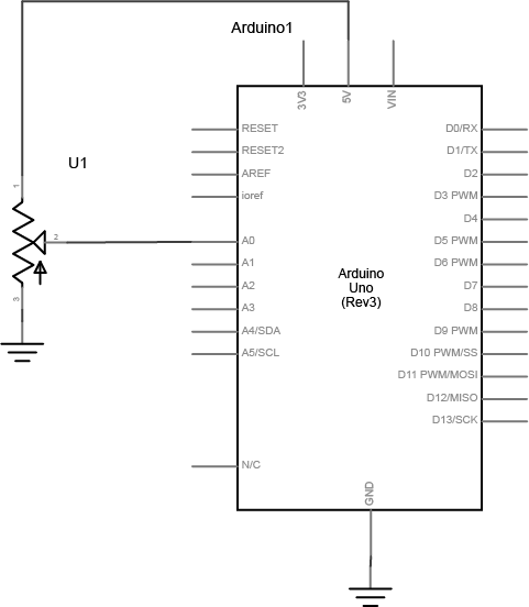
Figure 13. Schematic view of a potentiometer connected to analog in 0 of the Arduino
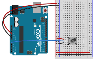
Figure 14. Breadboard view of a potentiometer connected to analog in 0 of an Arduino Uno. The potentiometer is mounted in three rows of the left center section of the breadboard. The two outside pins of the potentiometer are connected to the voltage and ground bus rows, respectively. The center pin is connected to analog in 0 of the Uno.
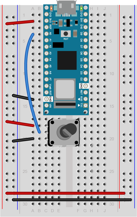
Figure 15. Breadboard view of a potentiometer connected to analog in 0 of an Arduino Nano. The potentiometer is mounted in three rows of the left center section of the breadboard below the Nano. The two outside pins of the potentiometer are connected to the voltage and ground bus rows, respectively. The center pin is connected to analog in 0 (physical pin 4) of the Nano.
Connect a Transistor to the Microcontroller
The transistor allows you to control a circuit that’s carrying higher current and voltage from the microcontroller. It acts as an electronic switch. You can use a bipolar Darlington transistor like the TIP120, or you can use a MOSFET like the IRF520 or FQP30N06L for this lab. All three will work the same way and use the same circuit. See Figures 16 through Figure 19 for the drawings and schematic symbols of the transistors.
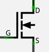
Figure 16. Pinout drawing of a TIP-120 transistor. From left to right the legs are labelled 1. base, 2. collector, 3. emitter.Figure 17. The schematic symbol of an NPN transistor. B is the base, C is the collector, and E is the emitter.Figure 18. NPN Transistor and N-Channel MOSFET side by side with a schematic diagram of the MOSFET. G is the gate (equivalent of base), D is the drain (collector) and S is the source (emitter).Figure 19. Schematic symbol of an N-channel MOSFET, where G is the gate (equivalent of base), D is the drain (collector) and S is the source (emitter).
The IRF520 MOSFET has the same pin configuration as the TIP120, and performs similarly with a 5V gate voltage. The FQP30N06L MOSFET has the same pin configuration, and operates on as low as 1.0V, and works well for 3.3V applications. MOSFETs can generally handle more amperage and voltage, and switch a little faster (the difference is in microseconds, so you won’t notice), but they are more sensitive to static electricity damage. They are grouped into N-Channel and P-Channel, which are equivalent to NPN and PNP bipolar transistors.
All three transistors mentioned here are designed for switching high-current loads. All of them have built-in protection diodes. Each has three connections Table 1 below details their connections.
Bipolar Transistor
MOSFET
Connection
Base
Gate
Connects to microcontroller output
Collector
Drain
Connects to power through load
Emitter
Source
Connects to ground
Table 1. Names of the pins on the bipolar transistor and the equivalent names on the MOSFETs
The datasheets for each of the recommended transistors can be found below:
Here’s the main operating principle of using a transistor as a switch: When a small voltage and current is applied between the base (or gate) and the emitter (or source), the transistor allows a larger current to flow between the collector (or drain) and emitter (or source).
Figures 20 through 22 show how to connect the transistor’s input to the microcontroller’s output. Note that this circuit isn’t complete, because the transistor isn’t controlling anything yet.
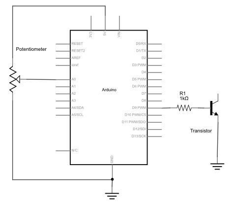
Figure 20. Schematic view of a potentiometer and transistor connected to an Arduino. First leg of the potentiometer is connected to +5 volts. The second leg connected to analog in 0 of the Arduino. The third leg is connected to ground. The base (or gate) of the transistor is connected to digital pin 9 of the Arduino through a 1-kilohm resistor. The emitter (or source) is connected to ground.
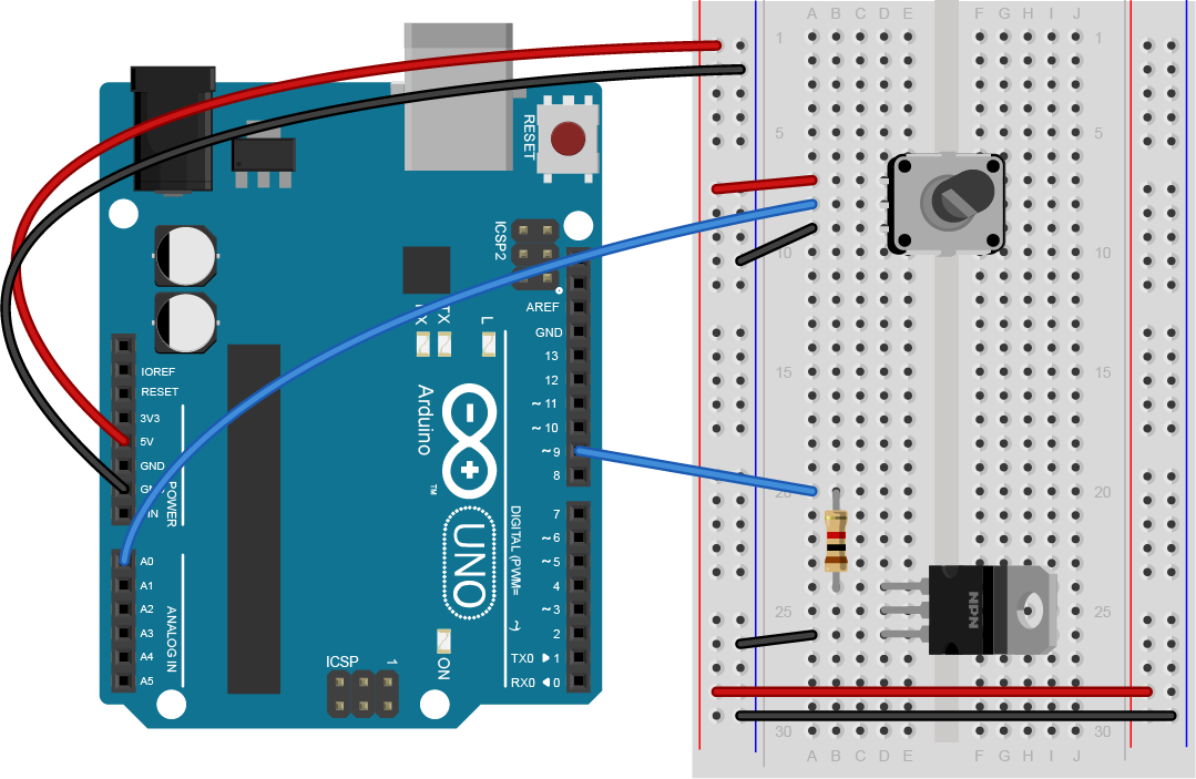
Figure 21. Breadboard view of a potentiometer and transistor connected to an Arduino. First leg of the potentiometer is connected to +5 volts. The second leg connected to analog in 0 of the Arduino. The third leg is connected to ground. The base (or gate) of the transistor is connected to digital pin 9 of the Arduino through a 1-kilohm resistor. The emitter (or drain) is connected to ground.
Figure 22. Breadboard view of a potentiometer and transistor connected to an Arduino Nano. First leg of the potentiometer is connected to +3.3 volts. The second leg connected to analog in 0 of the Arduino. The third leg is connected to ground. The base (or gate) of the transistor is connected to digital pin 9 of the Arduino through a 1-kilohm resistor. The emitter (or drain) is connected to ground.
Connect a Motor and Power Supply
Attach a DC motor to the collector (or drain) of the transistor as shown in Figures 23 through 25. Most motors will require more current than the microcontroller can supply, so you will need to add a separate power supply as well. If your motor runs on around 9V, you could use a 9V battery. A 5V motor might run on 4 AA batteries (6V). You could also use a 12-volt DC wall adapter and a 5-volt regulator. A 12V battery may need a 12V DC wall adapter, or a 12V battery. The ground of the motor power supply should connect to the ground of the microcontroller on the breadboard.
Add a 1N4001 power diode in parallel with the collector and emitter of the transistor, pointing away from ground. The diode protects the transistor from back voltage generated when the motor shuts off, or if the motor is turned in the reverse direction. Used this way, the diode is called a protection diode or a snubber diode. You can omit the diode if you don’t have one, as the transistors recommended here all have a built-in protection diode
Figure 23. Schematic view of a potentiometer connected to analog in 0 of the Arduino. A transistor is connected to Digital Pin 9. A DC motor connects to the transistor and a DC jack. The DC jack connects its positive wire to the first wire of the DC motor. The negative wire of the DC jack connects to ground. The second wire of the DC motor connects to the collector (or drain) of the transistor. A 1N400x diode’s anode is connected to the collector (or drain), and its anode is connected to ground.
Figure 24. Breadboard view of an Arduino connected to a potentiometer, a transistor, a DC motor, and a DC jack. A transistor is connected to Digital Pin 9. A DC motor connects to the transistor and a DC jack. The DC jack connects its positive wire to the first wire of the DC motor. The negative wire of the DC jack connects to ground. The second wire of the DC motor connects to the collector (or drain) of the transistor. A 1N400x diode’s anode is connected to the collector (or drain), and its anode is connected to ground.
Figure 25. Breadboard view of an Arduino Nano connected to a potentiometer, a transistor, a DC motor, and a DC jack. A transistor is connected to Digital Pin 9 through a 1-kilohm resistor. A DC motor connects to the transistor and a DC jack. The DC jack connects its positive wire to the first wire of the DC motor. The negative wire of the DC jack connects to ground. The second wire of the DC motor connects to the collector (or drain) of the transistor. A 1N400x diode’s anode is connected to the collector (or drain), and its anode is connected to ground.
Be sure to add the diode to your circuit correctly. The silver band on the diode denotes the cathode which is the tip of the arrow in the schematic, like so in Figure 26:
Figure 26. Schematic representation and physical representation of a diode. The silver band on the diode indicates the anode end.
Connect a Lamp Instead of a Motor
You could also attach a lamp using a transistor. There are many 12V incandescent lamps, designed for use in track lighting, gallery lighting, and so forth. Nowadays, there are many 12V DC LED equivalents of the 12V AC lamps as well. Here are a few examples:
The lamp circuit in Figures 27 through 29 assumes a 12V lamp. MOSFETs are generally best for switching incandescent and LED lamps, so the circuit below uses a MOSFET. In the lamp circuit, the protection diode is not needed, since there’s no way for the polarity to get reversed in this circuit.
Figure 27. Schematic view of a potentiometer, MOSFET, and lamp connected to an Arduino. The gate of a MOSFET transistor is connected to Digital Pin 9 of the Arduino. A 12V lamp connects to the drain of the transistor and a DC jack. The DC jack connects its positive wire to the first wire of the lamp. The negative wire of the DC jack connects to ground. The second wire of the lamp connects to the drain of the transistor. The source of the transistor connects to ground.
Figure 28. Breadboard view of a potentiometer, MOSFET, and lamp connected to an Arduino. The gate of a MOSFET transistor is connected to Digital Pin 9 of the Arduino. A 12V lamp connects to the drain of the transistor and a DC jack. The DC jack connects its positive wire to the first wire of the lamp. The negative wire of the DC jack connects to ground. The second wire of the lamp connects to the drain of the transistor. The source of the transistor connects to ground.
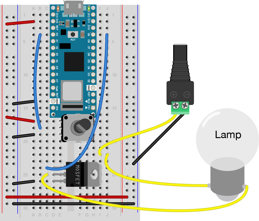
Figure 29. Breadboard view of a potentiometer, MOSFET, and lamp connected to an Nano. The gate of a MOSFET transistor is connected to Digital Pin 9 of the Nano. A 12V lamp connects to the drain of the transistor and a DC jack. The DC jack connects its positive wire to the first wire of the lamp. The negative wire of the DC jack connects to ground. The second wire of the lamp connects to the drain of the transistor. The source of the transistor connects to ground.
Program the microcontroller
Write a program to test the circuit, whether it’s a motor or a lamp. Your program should make the transistor pin an output in the setup method. Then in the loop, it should turn the motor on and off every second, just like the blink sketch does.
const int transistorPin = 9;    // connected to the base of the transistor

 void setup() {
   // set  the transistor pin as output:
   pinMode(transistorPin, OUTPUT);
 }

 void loop() {
   digitalWrite(transistorPin, HIGH);
   delay(1000);
   digitalWrite(transistorPin, LOW);
   delay(1000);
 }
Now that you see it working, try changing the speed of the motor or the intensity of the lamp using the potentiometer.
To do that, read the voltage of the potentiometer using analogRead(). Then map the result to a range from 0 to 255 and save it in a new variable. Use that variable to set the speed of the motor or the brightness of the lamp using analogWrite().
const int transistorPin = 9;    // connected to the base of the transistor

 void setup() {
   // set  the transistor pin as output:
   pinMode(transistorPin, OUTPUT);
 }

 void loop() {
   // read the potentiometer:
   int sensorValue = analogRead(A0);
   // map the sensor value to a range from 0 - 255:
   int outputValue = map(sensorValue, 0, 1023, 0, 255);
   // use that to control the transistor:
   analogWrite(transistorPin, outputValue);
 }
For the motor users: A motor controlled like this can only be turned in one direction. To be able to reverse the direction of the motor, an H-bridge circuit is required. For more on controlling DC motors with H-bridges, see the DC Motor Control lab.
Come Up with an Application
Now that you’ve got motor or lamp control, come up with an application.
If you used a motor in this lab, consider any toys you have that have a motor you could take control over. Charley Chimp™ has a motor that’s easy to control from an Arduino, for example.
The guts of a Charley Chimp™ cymbal-playing monkey.
You’ve got the beginnings of a good desk lamp or table lamp, if you chose to use a light bulb in this lab. How will you control it? How will you mount the switchor the dimmer knob? You might also want to consider a gooseneck pipe to mount your socket on, and a socket that goes with it. Here are a few inspirations: