Look at the parts involved. Do you have them or can you get them? What will they cost?
Read the code. Make sure you know what every line of code does. Something that’s incidental to your needs may be causing you a problem that’s easy to solve.
What processor did they use? Do you have to use that same one? For example, if the tutorial uses basic IO, UART, SPI, I2C,Analog and/or PWM, chance are it can be done on any board. If it uses HID or USB Midi, chances are it’ll work on any USB-native board
Write a Guide to Getting Better Help on Troubleshooting:
Always include:
description of what you’re making
Circuit diagram (get in the habit of drawing them)
Photo of circuit
Power source
Link to code
Describe these:
Describe the expected behavior
Describe what is actually happening
Describe the steps you’ve taken so far
Test programs
A test does one thing. Like blink. Most library examples are good tests. When you are working on a complex project with multiple input and outputs, write a test to make sure each input and each output is working as you expect. Save your test programs, Becky you will need them to re-test as you add features to your project.
If a given component is not working, re-read the tutorial fir each component you are using. Chances are you overlooked a detail of how to make it operate properly.
Here are some tools for sharing circuits, code, and fabrication techniques with your classmates and instructors when you can’t be physically in the same place together.
epocCam – an app for iOS and Android that converts your mobile phone into a wireless camera for your computer. You run an app on your phone and on your personal computer, and your phone shows up as just another camera available to any Zoom, FaceTime, Skype, etc. Steve Daniels recommends you buy the app. It spares you a ton of ads AND give better reolsution / connection control. Delete the free version when you get the pay version.
IPevo document cameras. We have used these on the floor at ITP. They are good for circuit sharing in a studio or classroom setup. Canadianclassroom.com appears to have them in stock.
Text Tools
codeshare.io A shared code editing site. It’s very barebones, but it’s fast and easy to get set up and edit together in real time.
glitch.com makes it easy to share live code in HTML/JS/CSS and node.js projects, including p5.js
Microsoft Visual Studio Code is a decent text editor that is optimized for screen readers. If you have the Arduino IDE installed on your machine, the Arduino Plugin for VS Code makes a good screen reader-friendly editor. The Arduino plugin gives you access to most of the tools in the Arduino IDE: boards manager, library manager, examples, compile and upload, and serial monitor. The VS Live Share Plugin allows you to share code live with other users over a network in real time as well. Setup time for a group is not fast, though, and requires a login.
github – Github is the most common code management platform used at ITP. It’s very useful for managing code and circuit drawing versioning among a group. You’re probably using it right now, if you’re reading this.
p5live – allows you to share p5.js sketches and code in realtime.
Drawing Tools
When drawing circuits, using common [electronic schematic symbols] and sharing your drawings in editable formats like SVG (scalable vector graphics) makes it easier to share materials. Many beginners find schematics abstract at first, so breadboard-friendly drawing programs are handy as well.
mural.co A shared drawing board. There are many others available, but this one is particularly useful because it supports SVG import, meaning you can import parts that you export from other circuit drawing programs like Fritzing or Eagle. It also has a library of standard electrical schematic symbols, making it easy to share circuit drawing exercises in real time.
Fritzing is a circuit and schematic drawing program designed for electronics beginners. It supports drawing in breadboard view, schematic view, or printed circuit board (PCB) view. It can export many different image formats, and can be extended by making your own parts files. Many suppliers of hobbyist elextrinics parts make their parts available as Fritzing files, including Sparkfun and Adafruit, and others. Though it’s no longer free, it’s still open source, and the latest releases are in the gitHub repository, and the work is self-financed by the maintainer, so the price is a good deal.
Tinkercad is another berginner-friendly circuit drawing environment. It’s not apparent how to import parts into it, however.
Inkscape is a free and open source vector drawing tool.
Sketch is another popular vector drawing tool among graphic designers.
Connected tools
The TS04 Multimeter (Amazon Canada link, thanks Steve Daniels) is a multimeter that connects to an Android/iOS app that works through a screen reader. It is possible to write your own HTML interface for the TS04 meter as well, using the web-bluetooth JavaScript framework. Here are some details on the TS04 protocol. You can connect to the connect to the TS04 meter from this link if you have one. This only works on the Chrome browser, as of this writing.
Students in Intro to Physical Computing and IMA Creative Computing will receive a kit of parts the following parts in class from their instructors:
Arduino Nano 33 IoT
830-point solderless breadboard
Jumper wire kit
USB micro cable
Force sensing resistors (FSRs), Qty. 3
4-paks of multicolor buttons (tactile switches), Qty. 2
10 -kilohm potentiometers, Qty. 3
Rotary encoders, Qty. 2
phototransistors, Qty. 6
RC servo motor and mounting components
right angle gear motor
TB6612FNG motor driver board
3″ diameter speaker, 4 ohm, 3W
VL53L0X time of flight distance sensor
The parts in the kit are your major components for the lab exercises in class. You will also need some components which you can find in the shop’s component stock, including resistors, LEDs, transistors, voltage regulators, capacitors, wire, and more. You can also find tools in the shop which you can use on the floor.
When you begin to work on your larger projects, such as the midterm and final, you will likely need to buy parts for yourself, depending on what you decide to build.
Shop Component Stock
The ITP/IMA shop stocks a number of consumable electronics components. This includes potentiometers, pushbuttons, phototransistors, resistors, capacitors, voltage regulators. These are kept in the bin racks in the shop, and are available for students to take as needed. Please take only what you need for a given class exercise, as stock re-supply is not fast, and we want to make sure everyone has the parts they need. Please inform shop staff if a given part is out of stock. It is possible to do all of the lab exercises in the intro classes with parts we have in in your kit, in shop stock, or in checkout.
Beyond this, students are expected to supply electronics parts for their projects. It’s not possible to anticipate every possible component that every project might need. However, we try to stock items to help you try things before you buy. Always consult with your instructors, shop staff, and research residents on how to choose the most appropriate and economical parts for your projects.
Check-out Components
The shop also has parts available for check-out with an NYU ID, just like the equipment room. These include microcontrollers, advanced sensors, and items which may be specific to various advanced classes. These must be returned after use, just like equipment room stock. You can check out components for up to two weeks at a time.
For other parts, talk to your instructors and the resident researchers. If you’re considering a part for your project, they can advise whether it’s the right part for the job, and if there’s one available for loan on the floor, they can procure it.
When You’re Done with Components
Many students at ITP/IMA don’t continue with electronics beyond the intro classes. If you have components in good condition that you’re no longer going to use, feel free to give them to shop staff or your instructors. We’ll do our best to keep components in use and out of landfills.
Shopping for Electronic Components
The intro kits and shop component stock can supply what you will need to complete the assigned lab exercises. For your project assignments, however, you may need a wider range of sensors and/or actuators.
Learning to shop for parts is a useful electronics skill, so we’ve assembled a number of Bills of Materials on Octopart to get you started. Octopart is a site that collects part data from multiple distributors around the world. They list several vendors from our suppliers list for each part. You may find this video about online electronics vendors and this video on how to use Octopart helpful as well.
We realize students will be shopping in many different regions of the world, and Octopart lists alternative vendors that supply as many regions as possible. Mouser, Digikey, and Arrow, all on Octopart, all have outlets in China, for example; Newark, Farnell all cover Europe and the Americas well; RS Components covers the Americas, Europe, and multiple countries in Africa. We have also put together a list of similar parts on Taobao as well. With these lists, you should be able to assemble the parts you need for the labs at the best price possible. Check each vendor to see what they charge to ship to where they are. If you know of a local vendor, feel free to use them instead.
There are a few lists on Octopart that you should pay attention to. The basic parts list and the tool list will get you through most of the labs in the class. For the last two labs in the semester, and probably for your last two project assignments, you’ll need to pick from the Sensor list and the Motor or Lighting lists.
ITP Pcomp Basic Parts – includes the parts you’ll need for the labs in most of the semester, including the breadboard and processor and components available in the shop component stock. This list is generally 100% in stock on Digikey, one of our most used vendors, as well.
ITP Tool List 2020 – The shop has hand tools available for students’ use, but if you want your own tools, this list includes basic hand tools you’ll need if you don’t already have them. Lists several options for each.
Advanced lists for later in the semester:
ITP Pcomp Sensor List – includes more advanced sensors. These are the kinds of sensors covered in the synchronous serial labs. This list will also be handy in later project assignments, when you’re looking for sensors specific to your project’s needs.
ITP Pcomp Motor List – includes parts for motor and mechanical projects, used in the motors and high current lab later in the semester. May be useful in some of your project assignments as well.
ITP Pcomp Lighting List – includes parts for LED lighting control, used in the motors and high current lab later in the semester. May be useful in some of your project assignments as well.
Can I Get a Starter Kit?
There are many Arduino starter kits on the market, but at the moment, none of them contain all the parts we recommend for this class. In particular, there is no kit for the Nano 33 IoT microcontroller yet. You can get a kit if you prefer, but you will likely have to shop for additional parts as well.
Components in Detail
The various types of parts you’ll find in the lists, and that you’ll need for the class, are detailed below.
Microcontroller
Used in most every week’s lab.
Figure 1. Arduino Nano 33 IoT
We’ll be working with the Arduino microcontroller platform. Recently we have switched to the Nano 33 IoT as our standard model. Most of the lab exercises are also compatible with the Arduino Uno, but the Nano 33 IoT offers some useful features that the Uno lacks, such as:
Ability to use Scheduler library for multiple loops
We have a guide to picking a microcontroller that may be helpful for more information. You can use any Arduino-compatible variant that you choose, and we’ll do our best to support you, but we can’t promise to know every variant on the market, there are several of dubious quality.
USB Cable
Used in most every week’s lab.
You’ll need a USB cable to connect your computer to your microcontroller as well. You can probably use one that you already have. The Nano 33 IoT has a USB Micro-B connector.
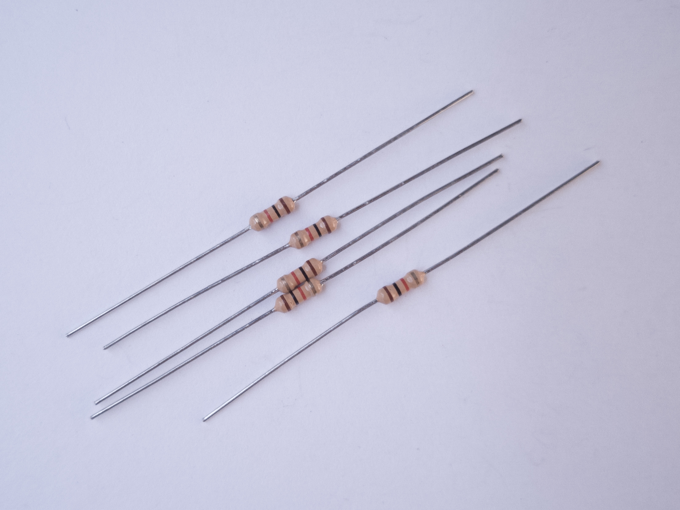
Resistors
Used in most every week’s lab.
Resistors. Shown here are Figure 2. 220-ohm resistors. You can tell this because they have two red and one brown band, followed by a gold band.Figuree 3. 1-kilohm resistors. These ones are 4-band resistorsFigure 4. 10-kilohm resistors. These ones are 5-band resistors
You’ll use resistors for many projects. The most common type you’ll need are 1/4 watt through-hole resistors in the values 220 ohm, 1 kilohm, and 10 kilohm. Occasionally, you might need other values as well, but most projects in this class can be done with combinations of those values. Resistors are usually bought in bulk, but there are also some handy resistor kits that contain samples of many different resistance values. A kit like this one from Sparkfun can last for a couple years of projects for the average electronics hobbyist
Breadboards
Used in most every week’s lab.
Figure 5. a solderless breadboard.
Most of your projects will be built on a solderless breadboard. There’s a lab to get you familiar with how they work. There are a few different models of these. The most common for this class are 16 x 54mm with 830 tie points and two vertical bus rows on either side. The smaller 84 x 54mm version with 400 tie points is also popular.
There are well-made breadboards, and there are cheap ones. Cheap ones seem like a good deal, but they can be difficult to use and easy to break components on. This chart compares different models of breadboards. Our favorites are from Jameco ValuePro, Twin Industries, and Bud Industries.
Breadboards can be reused for each lab, but sometimes it’s handy to have a spare.
For more permanent projects, you can use a printed circuit board to hold your components together. This requires you to solder each wire and component to the board, and cannot be disassembled, so it’s really only used for finished devices. There are some perma-proto boards with the same layout as a standard solderless breadboard that make transferring your circuit easy.
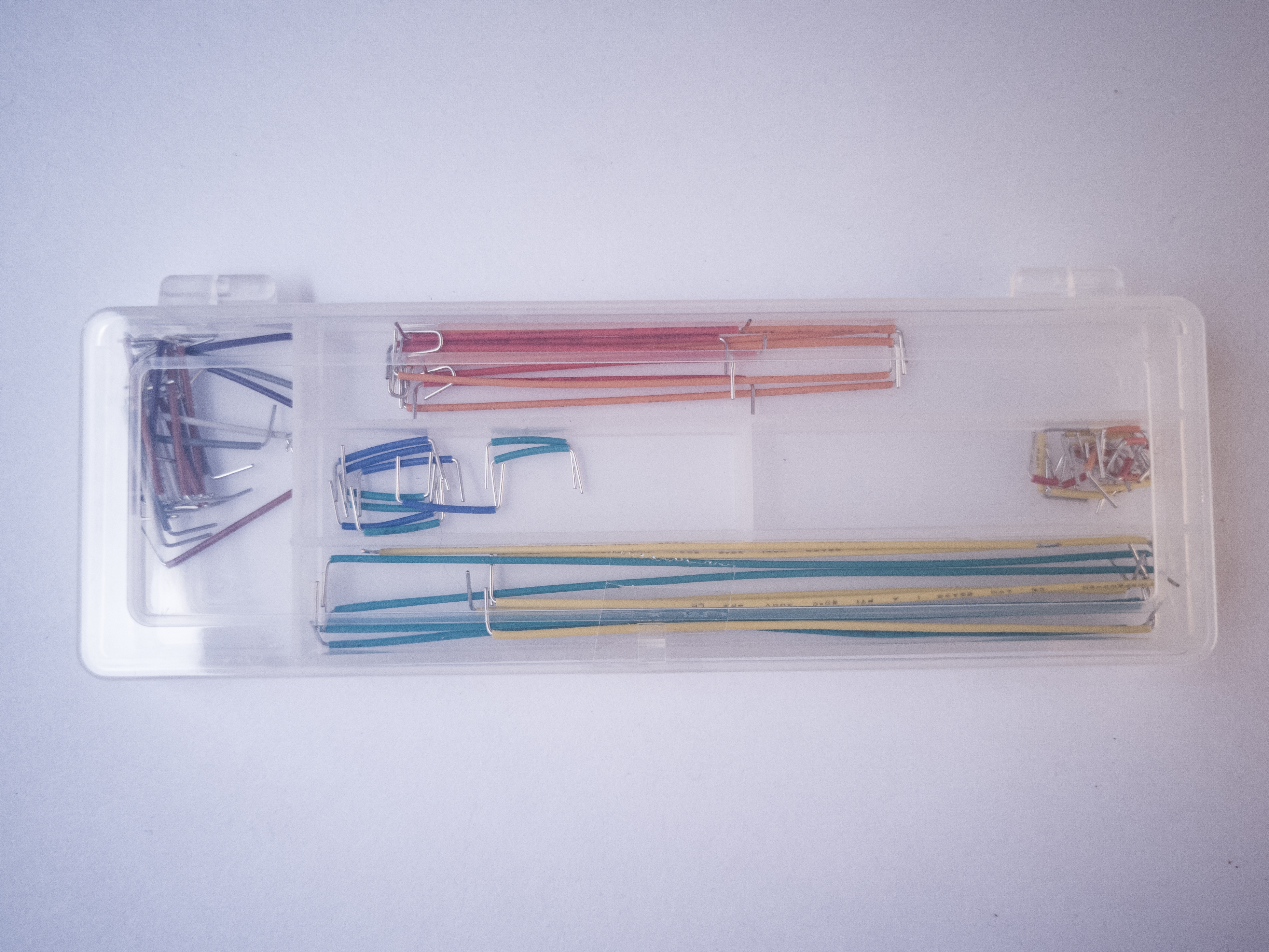
Wires
Used in most every week’s lab.
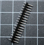
Figure 6. Flexible jumper wires.Figure 7. Pre-cut jumper wires. These ones are solid-core wires. They’re good for breadboards, but too stiff for general useFigure 8. Breakaway header pins
You’ll use a lot of wires to connect components on your breadboards. The breadboards support 22 AWG thickness wires. Some people prefer pre-cut solid core jumper wires, because they can lay flat on the breadboard and they insert into the board firmly. Others prefer flexible jumper wires because they’re easier to add and remove, so you can be spontaneous, but they make for a messier project, and are easy to accidentally pull out.
Another option is to order rolls of 22AWG solid core wire and custom cut your own jumper wires for each project. This is more time-consuming, but makes for a tidy and manageable board. Sometimes you can find multi-pack rolls of this wire in different colors like this one or this one. Here’s a wire options comparison list.
You might need some header pins as well, to solder on to wires and components. These are metal pins, spaced 0.1″ (2.54mm) apart, held together with plastic spacers.
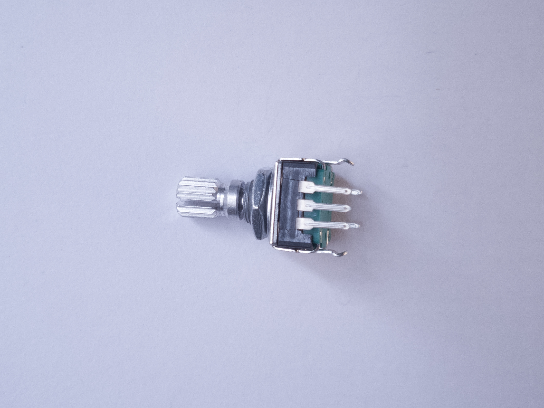
Basic Input And Output Components
Used in most every week’s lab.
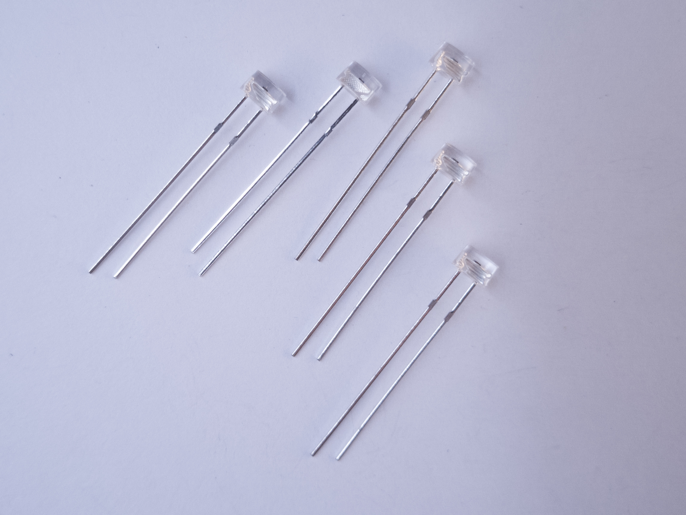
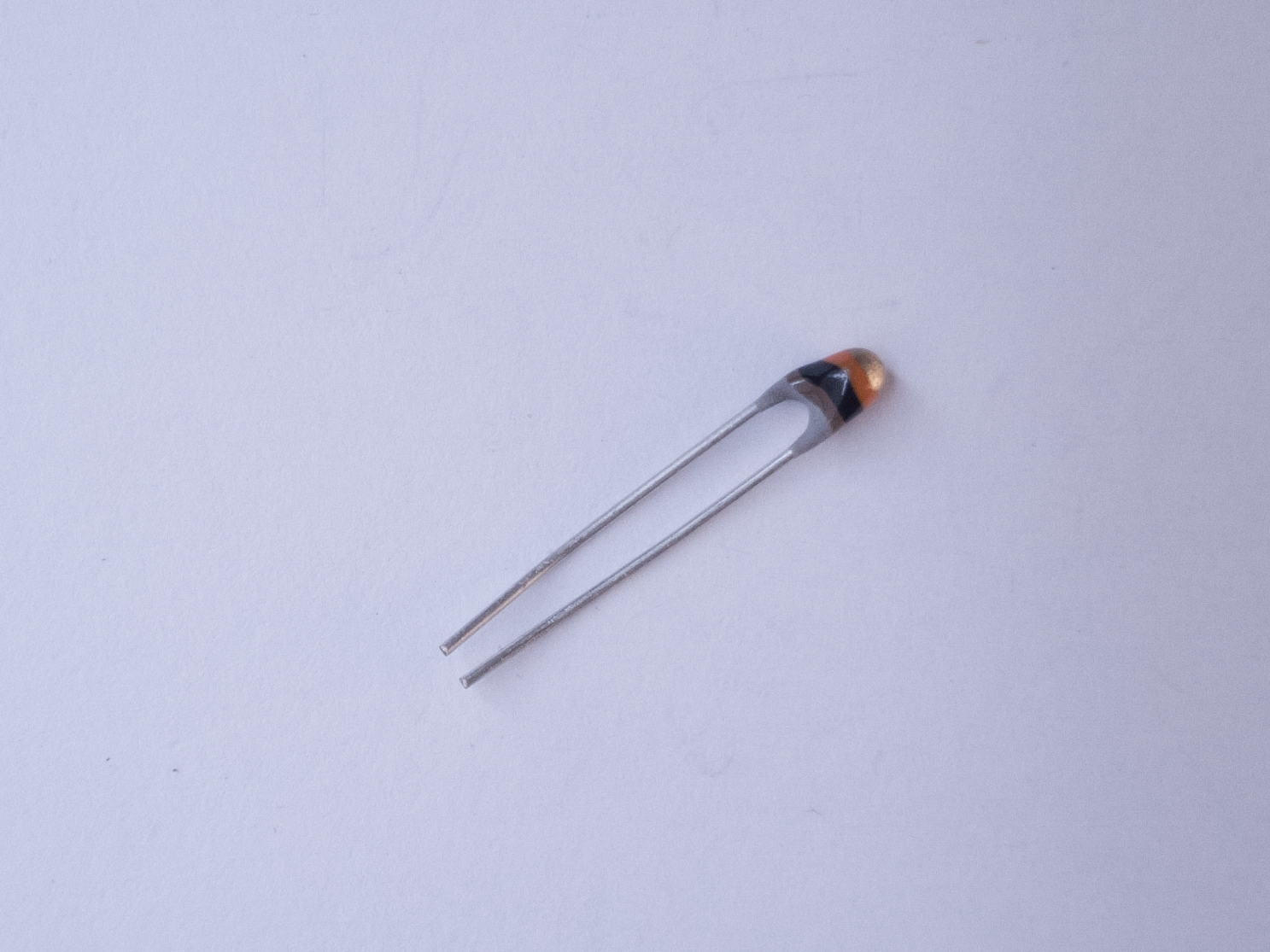
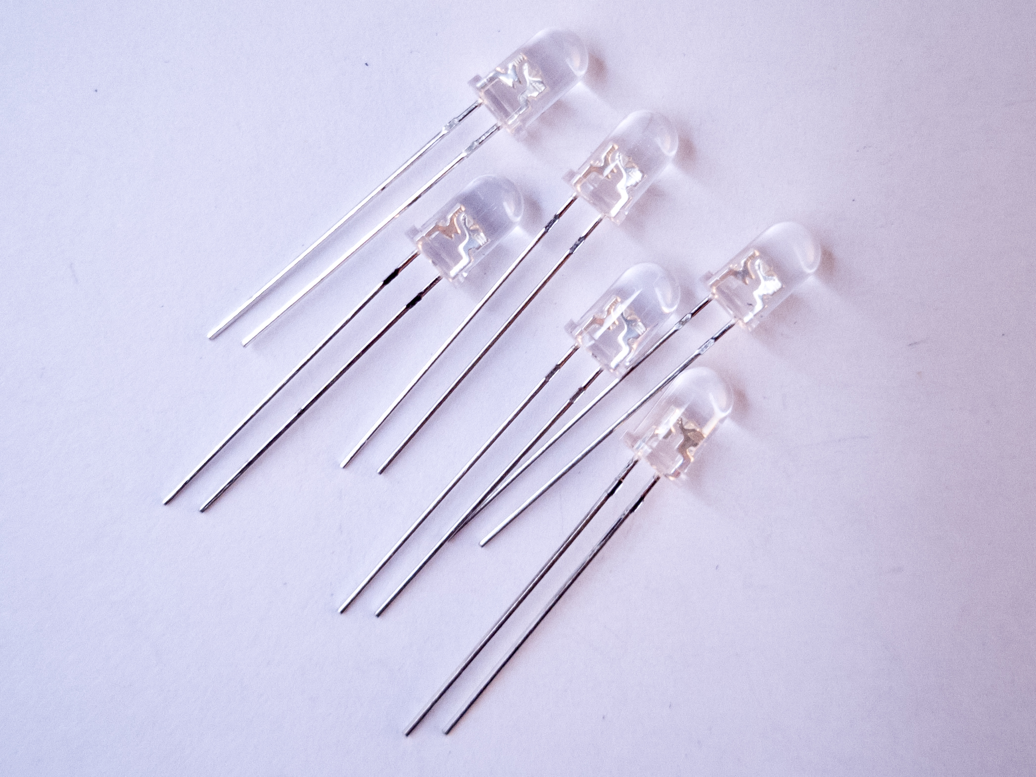
Figure 9. PotentiometerFigure 10. Rotary encoderFigure 11. Phototransistors. The short leg goes to voltage, and the long leg goes to the input pin of a microcontroller.Figure 12. ThermistorFigure 13. Force Sensing Resistor (FSR)Figure 14. LEDs. The long leg goes to voltage and the short leg goes to groundFigure 14. 4- to 8-ohm speaker
For most of the labs and many projects, you’ll use pushbuttons, switches, variable resistors called potentiometers, light emitting diodes (LEDs), speakers and/or piezo buzzers, and perhaps some variable resistors like force-sensing resistors (FSRs) or force-sensing potentiometers (FSPs). These are common and inexpensive components available from most electronic vendors. Make sure that the parts you get can be inserted into a solderless breadboard, or you will have to solder wires onto them.
Advanced Sensors
Used in labs around mid-semester; probably in later projects as well. Check shop check-out components for a variety of sensors.
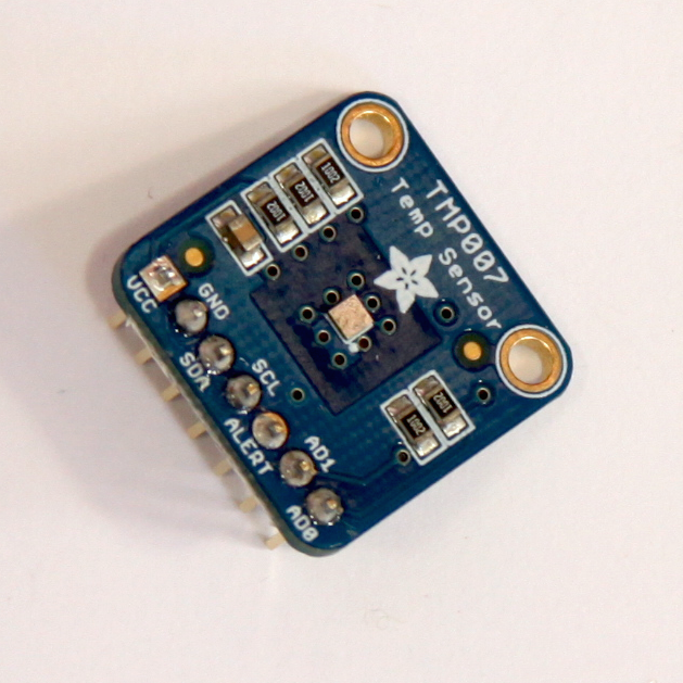
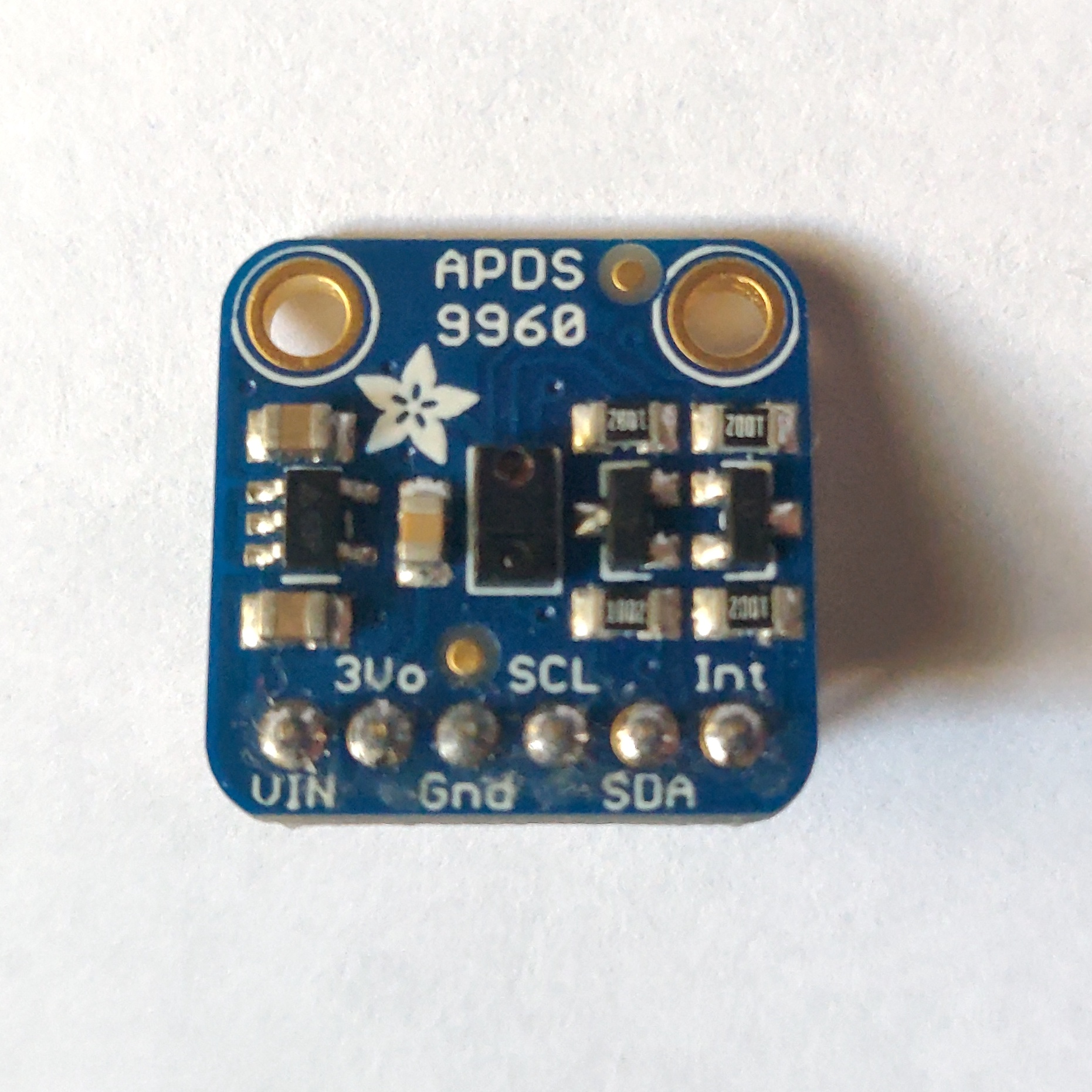
Figure 16. TMP007 infrared temperature sensorFigure 17. APDS-9960 color, gesture, and light sensorFigure 18. Breakaway header pins. You’ll need these to attach breakout boards to your breadboard.
There are many advanced sensors that are very useful in this class. The Nano 33 IoT has one built-in, an inertial measurement unit (IMU) that can measure tilt and rotation. There are light sensors, distance sensors, rotation sensors, environmental sensors, air pressure sensors, and many more. Most of these are sold on breakout boards that have holes for pins that can be fitted to a solderless breadboard. You’ll need to solder on header pins for most of them, and you’ll need to learn their communications protocols. You’ll learn about these in labs in the middle of the semester. There’s an Octopart Bill of Materials that lists several of these. You’ll need to pick one for the synchronous serial lab and by then you’ll have an idea which one might also work well for you in a project. Hold off on getting these until mid-semester.
Motors and Motor Accessories
Used in labs later in semester; possibly in later projects as well.
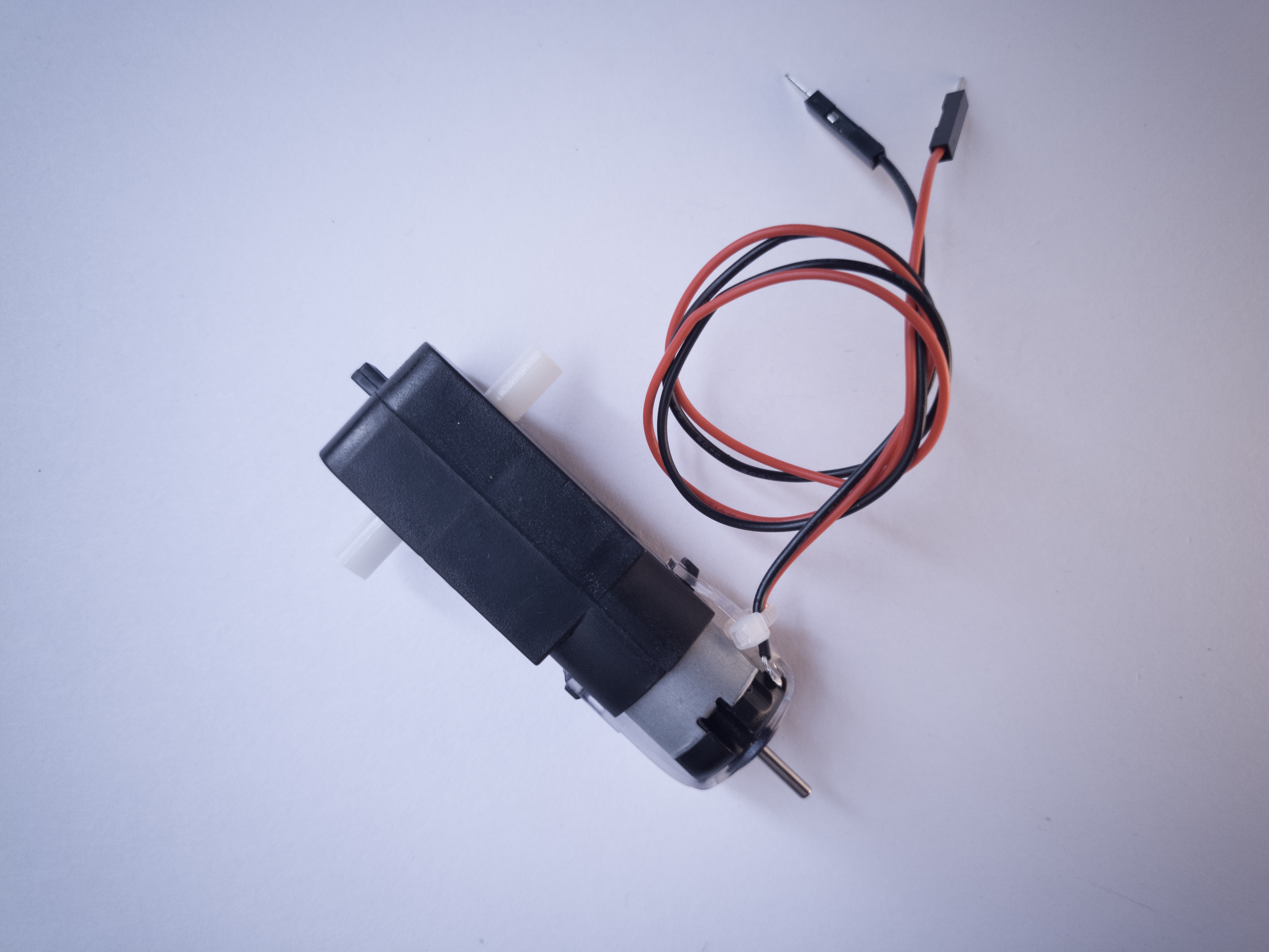
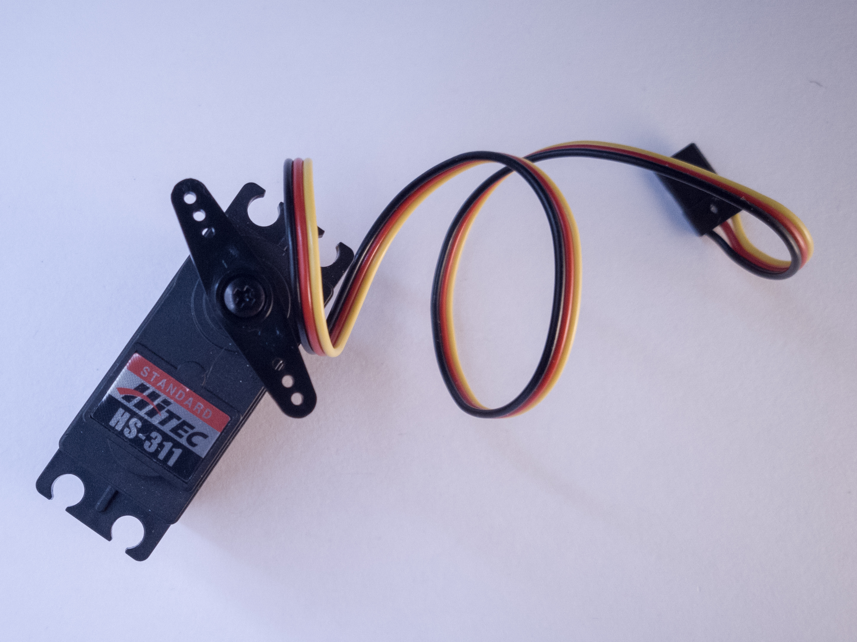
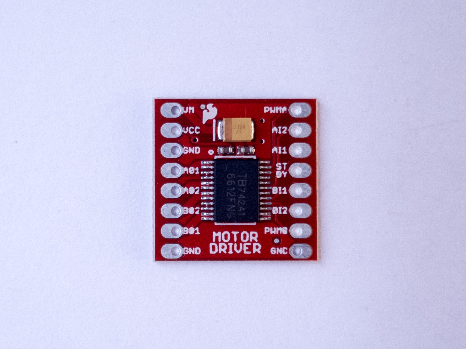
Figure 19. DC GearmotorFigure 20. RC Servomotor Figure 21. TB6612FNG Motor driver module.
There are labs on controlling servomotors, DC motors, and stepper motors in this class, and the parts BOM lists a few we recommend. However, there is not a mechanics module to this class and the motor lab is later in the semester, so if you’re not interested in mechanical motion, you may not need motor parts. Hold off on getting these until mid-semester.
Power Supply and Regulation
Used in many projects. Regulators and jacks available in the shop component stock.
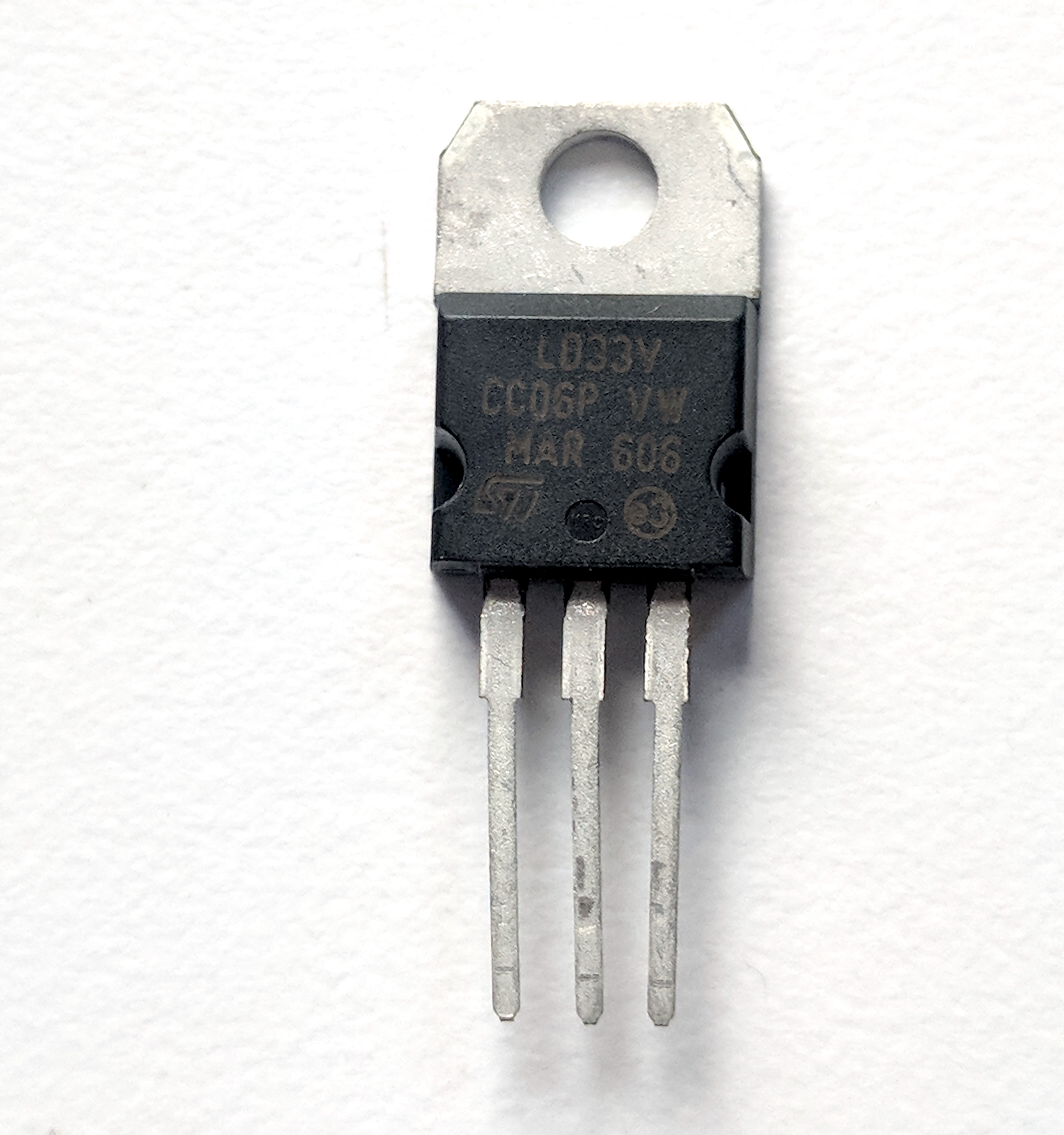
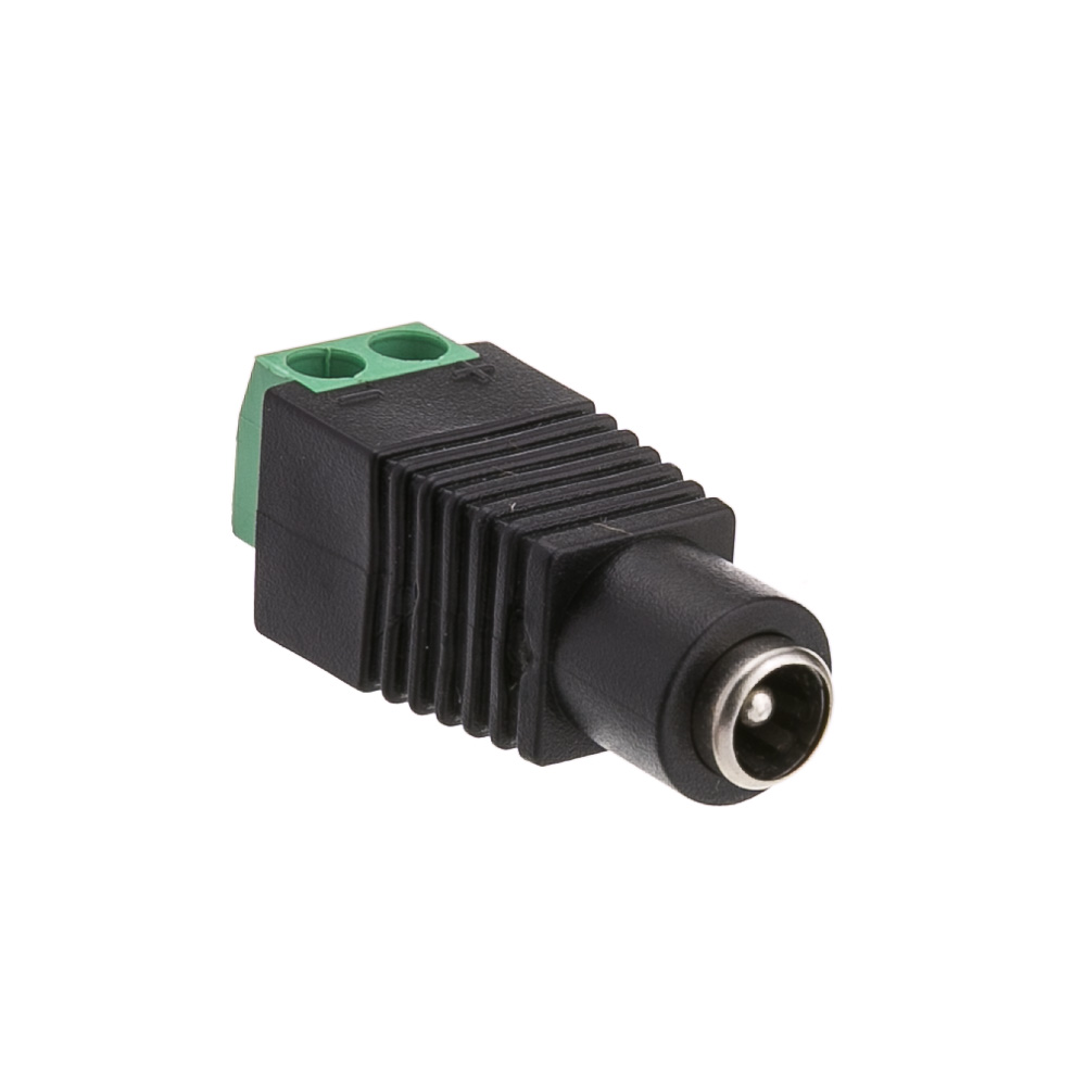
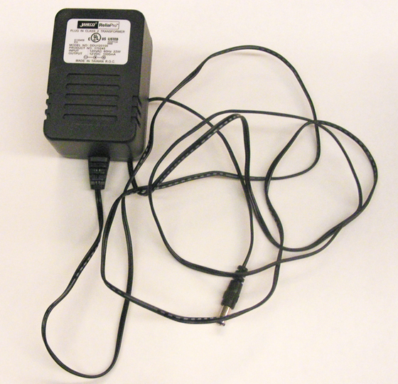
Figure 22. 3.3V voltage regulator. 5V regulators and many transistors you’ll use in this class look just like this, so read the label!Figure 23. A DC Power Jack. There are also DC power plugs that pair with this model. Figure 24. DC Power Supply. You may have one of these at home already. Check the supply of any discarded devices you have.
Though you can power most Arduino sensor projects from the USB port of your computer, you may want to make a project that doesn’t attach to your computer. For this you’ll need a power supply. You may have one at home already. If you don’t have one, you can wait until you are working on a project that needs it. You probably won’t need one in the first couple of weeks of the semester.
If your device can run on less than 500 milliamps and 5 or 3.3 volts, you can power it from a USB cable via your Arduino, and a USB AC to DC power adapter like the ones that you use to charge your phone can run the project .
For some projects, you may need more than a v-volt supply. A 12-Volt AC to DC converter that can supply 1000 or more milliamps is a good general supply. Many will already have a 2.1mm x 5.5mm DC barrel jack connector. There are DC barrel jack and plug adapters in the parts BOM that can connect to this type of connector.
Electronics Tool Kit
Used every week.
The shop stocks a full set of electronics tools which you can use. If you plan to do more electronics on your own, there are a few tools you should pick up for yourself, so you’ve always got a reliable set handy. These are common tools, and you can find them at any electronics retailer or hardware store. The ITP Tool List 2020 includes basic hand tools you’ll need if you don’t already have them. It lists several options for each, for comparison.
The electrical tools and hand tools below are ones you’ll use most every week and every project. You probably won’t need a soldering iron and soldering hardware right away, but you’ll use it frequently, from about week 2 or 3. The rest of the tools are less critical, or optional.
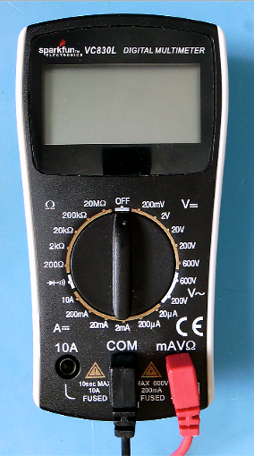
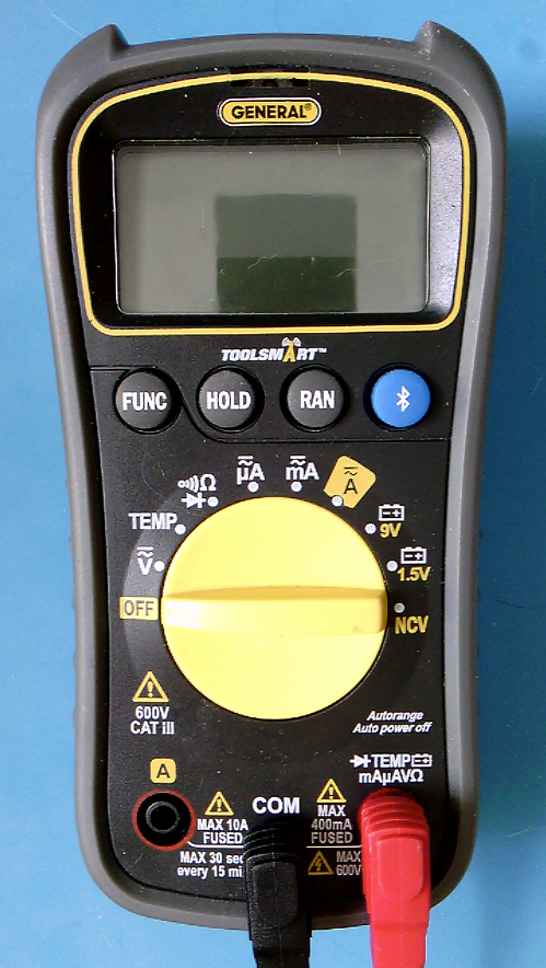
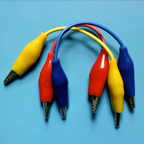
Figure 25 A non-autoranging multimeter. Each property has multiple possible range settings.Figure 26. An autoranging multimeter. It has only one setting for each function and the meter automatically detects the range.Figure 27. Alligator clips. These are wire leads with metal clips on either end, useful for quick and temporary connections in a circuit. They come in various lengths.
Digital Multimeter – You don’t need a fancy multimeter. One that measures voltage, current, continuity, and resistance will do the job.
Alligator Test Leads – these are wires with clips on the end, handy for when you’ve got components to test that can’t fit in a breadboard and that you don’t want to solder yet.
Hand Tools
Used every week. Available for use in the shop.
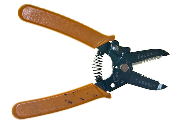
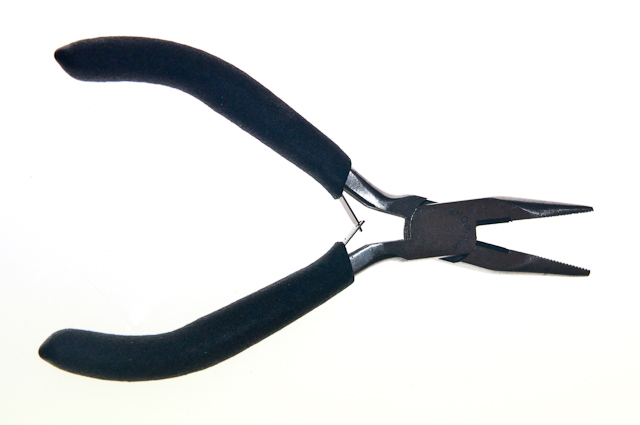
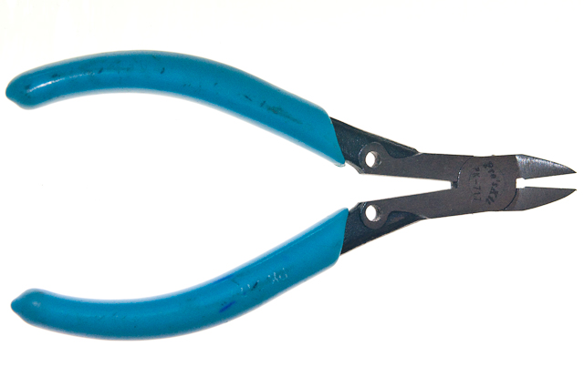
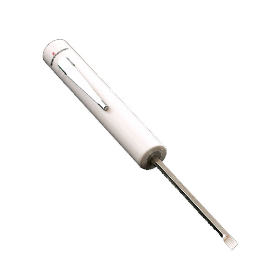
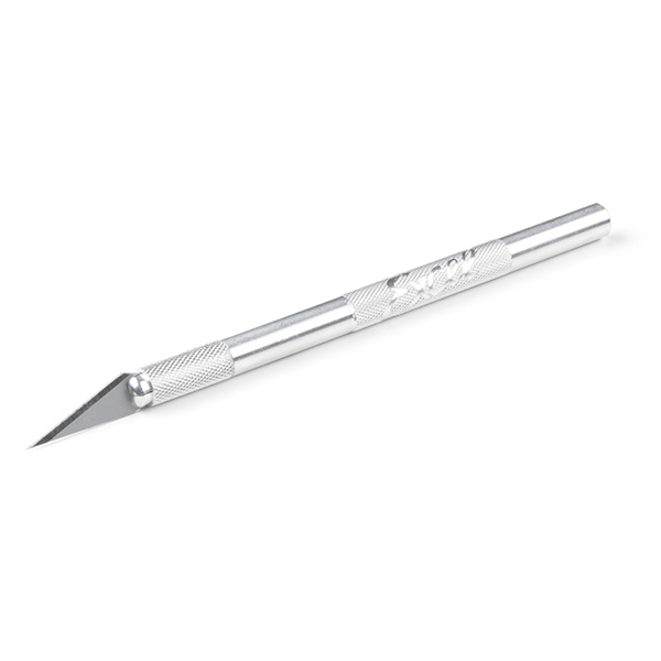
Figure 28. Wire stripper toolFigure 29. Needle-nosed pliersFigure 30. Diagonal cuttersFigure 31. Mini screwdriverFigure 32. Hobby knife. Photo from Sparkfun.
You’ll use hand tools frequently in this class. You may have some of these already.
Wire Strippers, 20-30AWG – These allow you to strip the insulation from wires. The most common wire you’ll use is 22AWG thickness, so use a stripper that can strip wires in that range.
Needle Nose Pliers – These are essential, you’ll use them a lot for pulling wires, bending wires, and picking up components.
Diagonal cutters – These are used for cutting wires and small bits of metal.
Mini Screwdriver – Get a mini screwdriver that has both flat and Philips heads. Many devices have small screws that you need to take out.
Hobby knife -Many people have something like this at home already, but if not, consider getting one. They are effective for cutting cardboard, mat board, and other soft materials.
Personal Protective Equipment (PPE)
Used occasionally. Available for use in the shop.
Safety Glasses – You should wear safety glasses when soldering or working with power tools.
Fume Extractor – for soldering, it’s a good idea to get a fume extractor, which is a fan and a charcoal filter that pulls the solder smoke away so you don’t breathe it in. They can be expensive, however. The one in the BOM is less expensive and aimed at hobbyists.
Soldering Hardware
Used occasionally. Available for use in the shop.
If you don’t have access to the shop, you might need a set of soldering tools., mostly for soldering header pins on breakout boards.
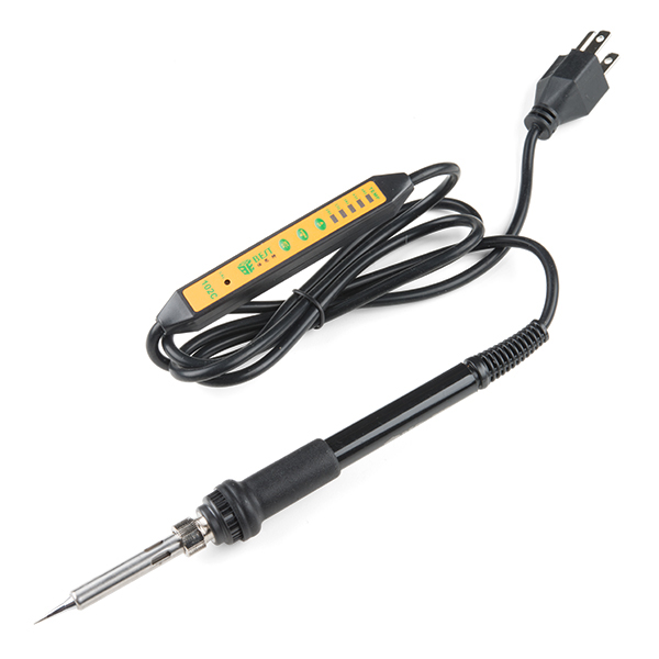
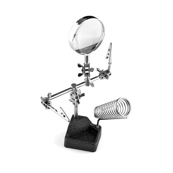
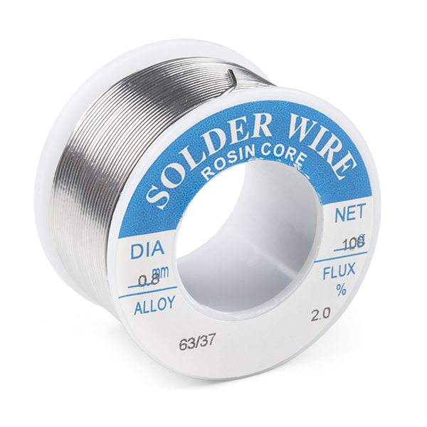
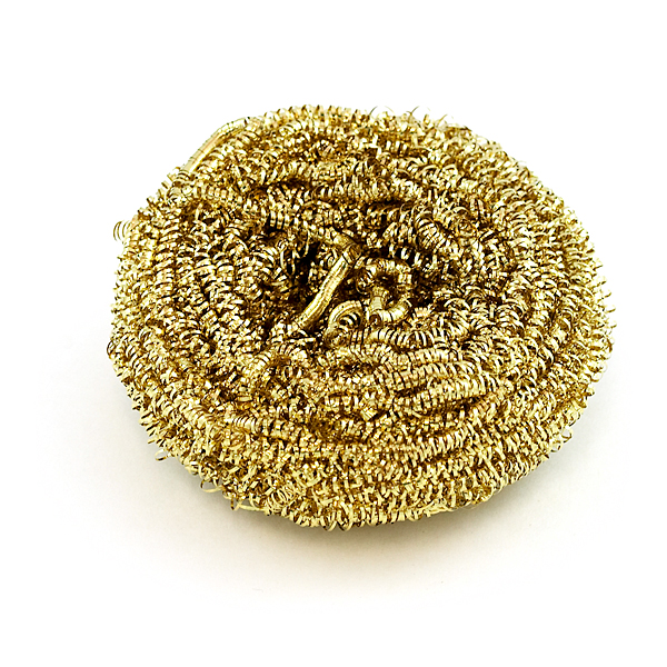
Figure 33. Soldering iron. This one has an adjustable temperature setting and an on-off switch on the cord. Photo from Sparkfun.Figure 34. Third hand soldering tool. Used to hold parts to be soldered together. This one has a stand for your soldering iron too. Photo from Sparkfun.Figure 35. Lead-free solder, 0.031″ guage. Don’t get solder that’s much thicker than this. Photo from SparkfunFigure 36. Brass sponge, used to clean the tip of a soldering iron. Better than a wet sponge for this job. Photo from Sparkfun.
Soldering Iron – The most common soldering you’ll do is breakout boards and some connectors. You don’t need a fancy iron, but a relatively fine tip is useful.
Extra soldering tip – make sure you get one that matches your iron
Solder – 18-22 AWG lead-free is the recommended choice for this class.
Third Hand – You’ll need something to hold the parts that you want to solder while you’re soldering, and this is the most basic tool for the job.
Solder Wick. – braided copper that you can use to wick solder away when you make a mistake. Solder and solder wick are expendable, you can only use them once, so you may need more if you solder frequently.
Solder Vacuum or Desoldering tool – A desoldering tool is another way to remove solder. You probably don’t need both this and solder wick as a beginner. Nice to have, but not essential.
Insulated Silicone Soldering Mat – This keeps your tabletop clean, and it’s also a good insulation so you avoid static discharge on the parts you’re working with. Nice to have, but not essential.
Brass Sponge – A tool for cleaning the tip of the iron. Don’t use a wet sponge, as it can rust your tip. Nice to have, but not essential.
Expendables
Optional
These are some materials you might find convenient in some projects.
Heat shrink tube – Shrinks down on a wire to make an insulator. Useful to tidy up projects.
Electrical tape – a quick insulating material
Copper tape – can be handy for making your own switches
Construction Materials
You’ll go through a lot of construction materials in this class. To save money and save the environment, consider reusing materials. Cardboard boxes and used plastic food containers can make great housings for electronic prototypes. Paper mat board and cardboard can make great housings and control surfaces as well. You will save yourself some money in the process if you do this. You’re not expected to make polished, production-ready devices in this class, so don’t waste time and money on high-end plastics and metals when you don’t have to.
For more information on parts, see the Suppliers page.
We use a few different microcontroller boards in this class over the years, but for each one, there is a standard way we lay out the breadboard. This page details those layouts. In any lab exercise, you can assume the microcontroller and breadboard are laid out in this way, depending on the controller you are using. Figures 1, 2, and 3 show the layouts of an Arduino Nano 33 IoT, an Arduino Uno, an Arduino MKR.
Nano Layout
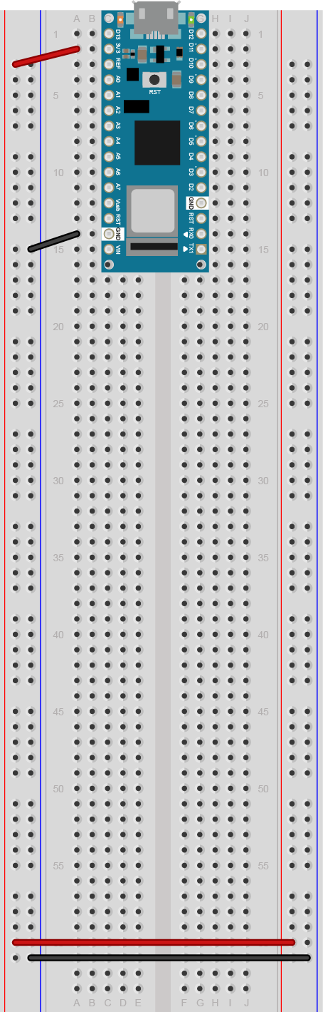
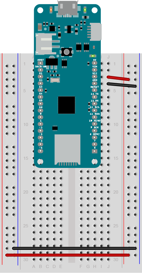
Figure 1. Breadboard view of an Arduino Nano on a breadboard
Figure 1. An Arduino Nano mounted on a solderless breadboard. The Nano is mounted at the top of the breadboard, straddling the center divide, with its USB connector facing up. The top pins of the Nano are in row 1 of the breadboard.
The Nano, like all Dual-Inline Package (DIP) modules, has its physical pins numbered in a U shape, from top left to bottom left, to bottom right to top right. The Nano’s 3.3V pin (physical pin 2) is connected to the left side red column of the breadboard. The Nano’s GND pin (physical pin 14) is connected to the left side black column.
These columns on the side of a breadboard are commonly called the buses. The red line is the voltage bus, and the black or blue line is the ground bus. The blue columns (ground buses) are connected together at the bottom of the breadboard with a black wire. The red columns (voltage buses) are connected together at the bottom of the breadboard with a red wire.
Uno Layout
Figure 2. Breadboard drawing of an Arduino Uno on the left connected to a solderless breadboard on the right
Figure 2. An Arduino Uno on the left connected to a solderless breadboard, right. The Uno’s 5V output hole is connected to the red column of holes on the far left side of the breadboard. The Uno’s ground hole is connected to the blue column on the left of the board. The red and blue columns on the left of the breadboard are connected to the red and blue columns on the right side of the breadboard with red and black wires, respectively. These columns on the side of a breadboard are commonly called the buses. The red line is the voltage bus, and the black or blue line is the ground bus.
MKR Layout
Figure 3. Breadboard view of an Arduino MKR series microcontroller mounted on a breadboard
Figure 3. An Arduino MKR series board mounted on a solderless breadboard. The MKR is mounted at the top of the breadboard, straddling the center divide, with its USB connector facing up. The top pins of the MKR are in row 1 of the breadboard.
The Nano, like all Dual-Inline Package (DIP) modules, has its physical pins numbered in a U shape, from top left to bottom left, to bottom right to top right. The MKR’s Vcc pin (physical pin 26) is connnected to the right side red column of the breadboard. The MKR’s GND pin (physical pin 25) is connected to the right side black column. These columns on the side of a breadboard are commonly called the buses. The red line is the voltage bus, and the black or blue line is the ground bus.
The blue columns (ground buses) are connected together at the bottom of the breadboard with a black wire. The red columns (voltage buses) are connected together at the bottom of the breadboard with a red wire.
Looking for inspiration for your PComp final? Want to see how previous students documented their projects? If you’re an alum and want your blog removed, let us know and we’ll take it off. If so, have a look at the below links to the Physical Computing blogs of ITP alumni. If you find a dead link please let us know about it.
You are expected to keep an online journal of your progress. Your instructors read your journals regularly to see how you are progressing, so you should update your journal regularly throughout the semester. At a minimum, we expect you to summarize any insights you have in each week’s lab assignments, to discuss to the readings, and to document your production projects and technical research thoroughly.
Please make sure your blog assignments are online the night before class (by 8 PM EDT, GMT-4) so that your instructors and classmates can read them before class.
Good documentation habits
Document your projects thoroughly as you go; don’t put it off until the end.
Documentation Platform
You may document your major projects in a separate individual or group site if you choose, but you will be expected to link your site to the your class page on this site. Please avoid formats that are not text-searchable, as they won’t show up on search engines for others to use.
Blogs are great for documenting your process, as they’re usually organized in reverse chronological order. However, they’re not a succinct way to showcase the way once it’s done. When you finish a project set up a separate page or pages on your site to summarize the project, so you can use this as a link in your portfolio.
Documenting Process
Good documentation should include a description and illustration of your project. Use pictures, drawings, and videos liberally to explain your work, although images alone usually don’t tell the whole story. Hence, you should include what it looks like, what it does, what the user or participant does in response. When it’s interactive, mention and show what the user does. Your explanation should give enough information that someone who’s never seen the project can understand it.
You should also include a section describing how the project works, aimed at a more informed reader (your instructor, or next year’s classmates). Include a system diagram to make clear what the major components of the system are and how they communicate.
Another important part is to include what didn’t work and what you struggled with. Describe in words your questions and things you don’t understand so you can bring up during class meetings or office hours.
Documenting Code
Make sure any code that you post is well-commented, so you and others can understand what it does. Don’t overload your notes with code. Code repositories like gitHub are best for sharing code, rather than blogs, so post your code to a repository and link to it from your blog.
If you are posting snippets of your code on your blog for quoting them in your post, refrain yourself rom adding screenshots of the IDE since it is not searchable and has a bad readability. Instead, cut and paste the code snippet or serial output on the IDE that you are referring to. Many blog platforms have features for posting code.
Documenting Circuits
Good documentation of circuits can help you communicate your circuit issues during class times and office hours efficiently. It’ll also become a useful reference for other classmates and yourself in the future. Uploading a picture of video of the breadboard itself does not guarantee a good readability of your circuits. Try drawing a diagram of your circuits either with your hands or on screen. The drawing process will help you understand your circuit better while producing a better documentation. You can also consider use circuit drawing software such as Fritzing.
Crediting Your Sources
Make sure to cite sources from which you get your ideas, code, circuits, and construction techniques. When you base your work on someone else’s, cite the original author and link to their work, just as you would when quoting another author in a paper. If you only changed one part of an existing program, post only the part you changed, and link to the original. Copying code or techniques without attribution is plagiarism. Few ideas come out of the blue, and your readers can learn a lot from the sources from which you learned and by which you were were inspired. So be generous in sharing your sources.
NYU offers access to and information on Zotero, which is a great tool for managing citation. Here’s an intro video. Zotero has a browser plugin that lets you save links to your account easily. You can generate collections of links like this from the app. You can even automatically generate citations for any source from the app. You can download the app and the browser plugin from this link.
This also applies to AI tools such as Chat GPT. Read Use of AI Policy for this class.
Nice project materials in FRSK04 by Sam Lavigne and Fletcher Bach
Nuntinee Tansrisakul’s Shadow through Time foregrounds the project itself, describing and showing the final device first, and then summarizing the components and the process.
This page lists tools, techniques, and resources that may be helpful to students with differing abilities who want to build the projects described on this site. It is a constant work-in-progress, so if you have suggestions for additions, please let us know.
General Resources
Tactile Schematics
The Physical Computing schematics redesigned for tactile use and a style guide for how to design them, available for download at tactileschematics.com.
APH has a good image library of SVG graphics that’s useful in a variety of educational subjects. The Mathematics ones are likely most relevant here. APH has other useful tools as well, like their Braille Blaster Braille conversion editor, and a few good talking calculators as well.
The Smith-Kettlewell Technical File
The Smith-Kettlewell technical file “was a publication by and for blind and visually-impaired electronics professionals and enthusiasts”. Running from 1980-1998, it covers a range of technical topics with practical advice on topics like soldering, using power tools, electronic components, logic tools and testers, and more. It’s useful for anyone interested in electronics, and formatted in a way that’s accessible for assistive reading devices like screen readers and Braille readers. Thanks to Ken Perry for the link.
Microsoft Visual Studio Code is a decent text editor that is optimized for screen readers. If you have the Arduino IDE installed on your machine, the Arduino Plugin for VS Code makes a good screen reader-friendly editor (thanks Ken, Josh and John Schimmel for the tip). The Arduino Plugin gives you access to most of the tools in the Arduino IDE: boards manager, library manager, examples, compile and upload, and serial monitor. The VS Live Share Plugin allows you to share code live with other users over a network in real time as well. The Accessibility for VS Code page is a useful intro to features in the editor.
On MacOS and Linux, the command line allows you to read input from a serial port just as you would from a file, using the cat command. cat /dev/cu.usbmodemXXXX will open an Arduino’s serial port, if no other application has it open already. control-C will close it. If you’ve got a continually repeating serial output, you may prefer to use the less command instead of the cat command. less /dev/cu.usbmodemXXXX will also print out the serial output, but it will stop after each screenful. Type the spacebar to page through multiple screens, or use the arrow keys to read up and down. Type q to exit.
The Emic2 test-to-speech module is an alternative to using the Arduino IDE Serial Monitor for debugging.It’s a piece of hardware that you can plug it into your Arduino’s serial transmit (TX) or softwareSerial transmit pin, and it will speak whatever you send out the serial pin via Serial.print(), Serial.println(), or Serial.write(). You can get it from Parallax, SparkFun or Adafruit. The Emic2 manual is available online. Here is a barebones code example for the Emic2. (Thanks to John Schimmel of DIYAbility for the tip)
Similarly, if you want a replacement for a dimming LED, use a speaker and the tone() function. An 8-ohm speaker will work pretty well with a 220-ohm resistor in series with it, so you can swap an LED for a speaker and swap analogWrite(pinNumber, x); for tone(pinNumber, x*10); in most cases and get an audible result, because analogWrite() takes a number from 0 to 255 as the second parameter, and a tone() from 200 – 2550Hz is reasonably audible.
Grove Components
SeeedStudio’s Grove components are useful for building projects without a breadboard. The Blind Arduino Blog has some notes on using Grove. In addition to the Grove Shield and the components, there’s also a MKR Connector Carrier that’s compatible with Grove for the MKR series Arduinos. Here are a few useful Grove part numbers from Digikey:
This page contains links to a few templates for commonly used design files. For more templates and construction designs, see See the ITP Fab site, http://itp.nyu.edu/fab
Small Breadboard Box. This design fits a small breadboard with a potentiometer or rotary encoder and some 3mm and 5mm LEDs. Can be made from thin cardboard or mat board. Breadboard box in SVG or Breadboard box in Illustrator CS6 format.
This page explains the basic pin functions that most microcontrollers share, and offers some tips for switching from one microcontroller to another. Since the tutorials on this site are all written with the Arduino Uno in mind, and students may be using other controllers, you may need to know how to “convert” a tutorial from the controller it’s written for to your own controller. In order to get the most out of it, you should know something about electrical circuits, and what a microcontroller is and what it can do. This video might help: Hardware functions in a microcontroller
What Do All These Pins Do?
A typical microcontroller can have between 6 and 60 pins on it, to which you’re expected to attach power connections, input and output connections, and communications connections. Every microcontroller has different configurations for its pins, and often one pin will have more than one function. This combining of functions on one pin is called pin multiplexing.
Every microcontroller has names for the pins specific to its hardware, but the Arduino application programming interface (API) provides a set of names for pins and their functions that should work across all microcontrollers that are programmable with the API. So, for example, A0 will always be the analog input pin 0, whether you’re on an Uno, 101, MKRZero, MKR1000, or other Arduino-compatible board. When you connect to the pin with the same function on another board, your code should operate the same, even though the physical layout of pins is different.
Every board has an operating voltage that affects its pins as well. The operating voltage, which is the same as the voltage of the GPIO pins, is labeled below. If you’re connecting a component to a board with a lower voltage than the component, you’ll need to do some level shifting.
Pin Diagrams
Microcontrollers typically come in a variety of physical forms, or packages. Sparkfun has a nice tutorial on integrated circuit package types if you want to know more. Pin numbering on any integrated circuit, including microcontrollers, starts at top left corner, which is usually marked with a dot. From there, you count around the chip counter-clockwise. For modules like the Arduino Uno, this numbering doesn’t hold up, since the board has several pin headers. The pin headers are usually numbered, and the pins of each header are counted. Unfortunately, header numbering does not always follow the same patterns as IC numbering.
Microcontroller pins are referred to by their physical pin (where they are physically on the board) and their functional pin names (what they do). For example, the Arduino Nano’s physical pin 20 is digital I/O pin 2.
Arduino Nano Series
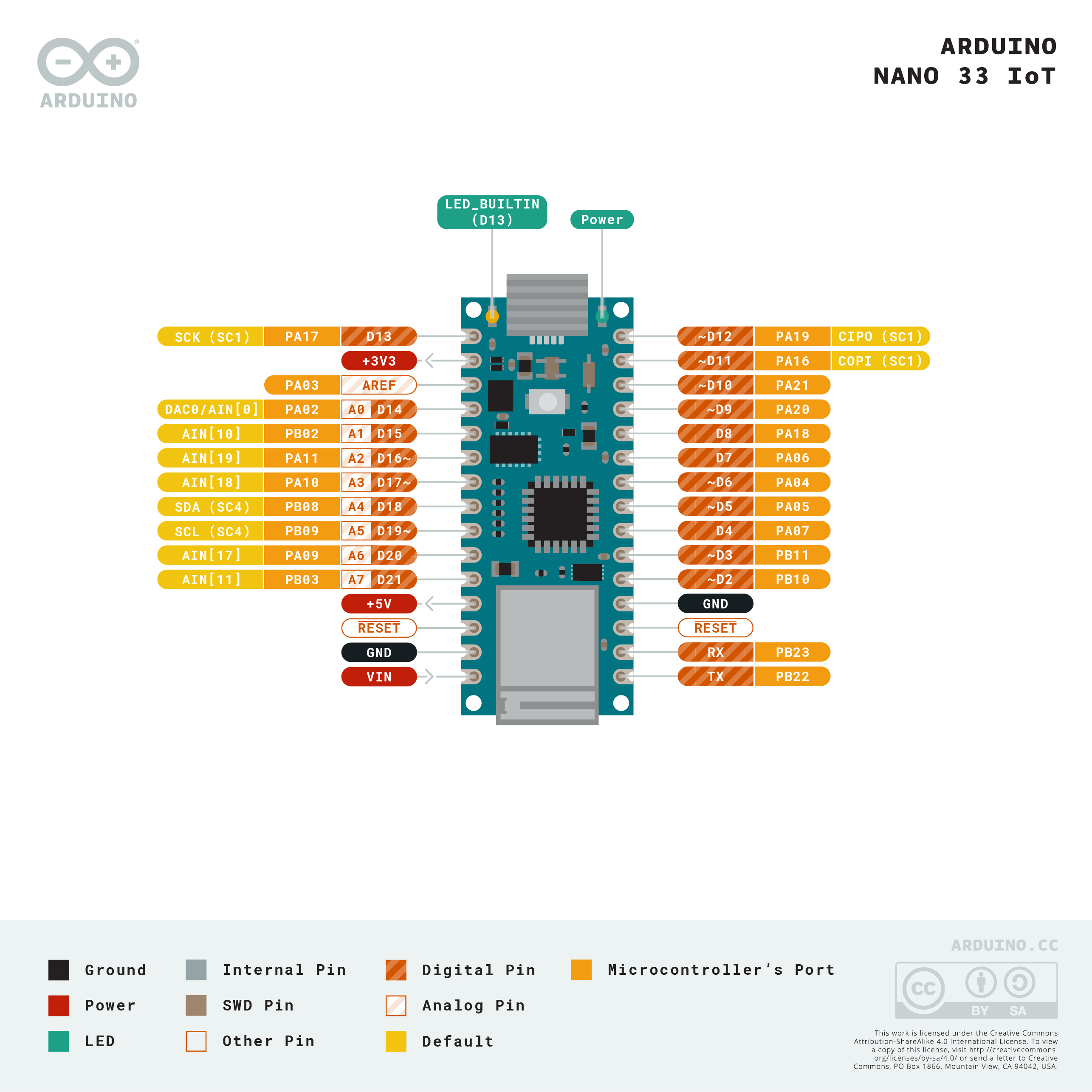
Arduino Nano 33 IoT Pin diagram
The Arduino Nano boards, like the Nano Every, Nano 33 IoT, Nano 33 BLE, Nano 33 BLE Sense, and Nano RP2040 Connect have a number of similar features. The Nano 33 IoT is shown in Figure 1, but the other Nanos have the same pin layout. The pin numbering follows the U-shaped pattern of a typical integrated circuit as described above; pin 1 is on the top left, and pin 30 is on the top right. The pins, summarized, are as follows:
Physical pin 1: Digital I/O 13
Physical pin 2: 3.3V output
Physical pin 3: Analog Reference
Physical pin 4-11: Analog in A0-A7; Digital I/O 14-21
Physical pin 12: VUSB (not normally connected)
Physical pin 13: Reset
Physical pin 14: Ground
Physical pin 15:Vin
Physical pin 16: Digital I/O pin 1; Serial1 UART TX
Physical pin 17: Digital I/O pin 0; Serial1 UART RX
Physical pin 18: Reset
Physical pin 19: Ground
Physical pin 20-30: Digital I/O pins 2-12
PWM Pins: on the Nano 33 IoT, the following pins can be used as PWM pins: digital pins 2, 3, 5, 6, 9, 10, 11, 12, A2, A3, and A5. One pin A0, can also be used as a true analog out, because it has a digital-to-analog converter (DAC) attached. On the Nano Every, only pins 3, 5, 6, 9, and 10 can be used as PWM pins. On the Nano 33 BLE, all digital pins can be used as PWM pins.
SPI Pins:
SDI- digital pin 12 (physical pin 30)
SDO – digital pin 11 (physical pin 29)
SCK – digital pin 13 (physical pin 1)
CS – digital pin 10 (physical pin 28)
I2C Pins:
SDA – pin A4 (physical pin 8)
SCL – pin A5 (physical pin 9)
UART Pins:
Serial 1 TX: digital pin 1 (physical pin 16)
Serial1 RX: digital pin 0 (physical pin 17)
Notes on the Nano Series
The Nano Every operates on 5V. The Nano 33 IoT, 33 BLE, and RP2040 Connect operate on 3.3V.
The Nano 33 IoT is based on the SAMD21 processor, just like the MKR boards. It has a NINA W102 radio that can communicate using Bluetooth 4.0 or WiFi, just like the MKR 1010. The RP2040 Connect has the same radio. It also has a real-time clock and an IMU sensor. For more on this board, see the Introduction to the Nano 33 IoT.
The Nano 33 BLE is based on the nRF 52840 microcontroller. It can communicate using Bluetooth 5.0
The Nano Every is based on the ATMega4809 microcontroller. It is functionally most similar to the Uno’s Atmega328 processor.
The Nano RP2040 Connect is based on the Raspberry Pi RP2040 processor, a dual SAMD21 processor.
On the Nano Every, pins 16 and 17 (TX and RX) are the serial port called Serial; they are also attached to the USB-Serial microcontroller on board. On the 33 IoT and 33 BLE, they are the serial port called Serial1 and are not attached to the USB serial port.
On the Nano 33 IoT as opposed to other Arduino Nano boards, pins A4 and A5 have an internal pull-up resistor and default to the I2C functions.
On the Nano 33 IoT and Nano 33 BLE, the VUSB pin does NOT supply voltage but is connected through a jumper, to the USB power input. You need to solder the jumper on the bottom of the board to use VUSB.
Interrupts: All the Nano 33 IoT’s, Nano 33 BLE’s, and Nano Every’s digital pins can be used as hardware interrupts. However, some repeat, so check the AttachInterrupt guide for the best pins to use as interrupts.
Arduino Uno Rev 3
Arduino Uno Rev 3 Pin diagram
The Arduino Uno Rev 3, shown in Figure 1, is the classic Arduino model. The pin numbering follows the U-shaped pattern of a typical integrated circuit as described above; pin 1 is on the top left, and pin 30 is on the top right. The pins, summarized, are as follows:
Physical pin 1: not connected
Physical pin 2: I/O reference voltage
Physical pin 3: Reset
Physical pin 4: 3.3V output
Physical pin 5: 5V output
Physical pin 6-7: Ground
Physical pin 8: Vin
Physical pin 9-14: Analog in A0-A5; Digital I/O 14-19
Physical pin 15-28: Digital I/O pin 0-13
Physical pin 29: Ground
Physical pin 30:Analog Reference
Physical pin 31: I2C SDA; Digital I/O pin 18; Analog in A4
Physical pin 32: I2C SCL; Digital I/O pin 19; Analog in A5
PWM Pins: on the Uno Rev 3, the following pins can be used as PWM pins: digital pins 3, 5, 6, 9, 10, 11.
SPI Pins:
SDI- digital pin 12 (physical pin 27; digital I/O pin 12)
SDO – digital pin 11 (physical pin 26; digital I/O pin 11)
SCK – digital pin 13 (physical pin 28; digital I/O pin 13)
CS – digital pin 10 (physical pin 25; digital I/O pin 10)
I2C Pins:
SDA – pin A4 (physical pin 13 or 31; Analog in pin A4)
SCL – pin A5 (physical pin 14 or 32; Analog in pin A5)
UART Pins:
Serial TX: digital pin 1 (physical pin 16)
Serial RX: digital pin 0 (physical pin 15)
Notes on the Uno Rev 3
At the bottom center of the Uno board is a six-pin connector called the In-Circuit Serial Programming connector (ICSP). It has two rows of pins, labeled as follows:
Top row (left to right): Reset, SCK, SDI
Bottom row (left to right): Ground, SDO, +5V
On the top right of the Uno is another six-pin connector. The Uno has a second microcontroller on board to handle USB-to-serial communications. This is the ICSP header for that microcontroller.
The Serial port called Serial is attached to pins 0 and 1, and to the USB-Serial micrcontroller on board.
Interrupts: on the Uno rev. 3, only digital pins 2 and 3 can be used as interrupts.
Arduino MKR Series
Mkr Zero Pin diagram
The Arduino MKR series are intended for advanced RF applications. They have the same SAMD Cortex M0+ as the Nano 33 IoT, and a built-in rechargeable battery connector and charging circuit. Like most of the Nanos, the MKRs are 3.3V boards. There are several boards in the MKR line for different connectivity needs:
The pin numbering follows the U-shaped pattern of a typical integrated circuit as described above; pin 1 is on the top left, and pin 28 is on the top right. The pins, summarized, are as follows:
Physical pin 1: Analog Reference
Physical pin 2-8: Analog in A0-A6
Physical pin 9-14: Digital I/O pin 0-5
Physical pin 15-23: Digital I/O pin 6-14
Physical pin 24: Reset
Physical pin 25: Ground
Physical pin 26: 3.3V output
Physical pin 27: Vin
Physical pin 28: 5V output
PWM Pins: on the MKR series, the following pins can be used as PWM pins: digital pins 0 – 8, 10, 12, analog pins A3, A4.
SPI Pins:
SDI- digital pin 12 (physical pin 19; digital I/O pin 10)
SDO – digital pin 11 (physical pin 17; digital I/O pin 8)
SCK – digital pin 13 (physical pin 18; digital I/O pin 9)
CS – any other digital pin
I2C Pins:
SDA – Digital I/O pin 11 (physical pin 19)
SCL – Digital I/O pin 12 (physical pin 20 )
UART Pins:
Serial TX: digital pin 14 (physical pin 21)
Serial RX: digital pin 13 (physical pin 20)
Notes on the MKR Series
Serial: The MKR series boards have two hardware UARTs.The first one, UART0 (aka Serial in your sketches) is attached directly to the USB port not to any pins. GPIO pins 13 and 14 are Serial1
Battery in: LiPo, 3.7V, 700mAh min Recharging circuit on board.
Interrupts: On the MKR series, pins 0, 1, 4, 5, 6, 7, 8, 9, A1, and A2 can be used as interrupts.
Pin Functions Explained
In order to make sense of all of this, it helps to know the general functions of a microcontroller. There are a few common functions:
Power: Every microcontroller will have connections for power (often labeled Vcc, Vdd, or Vin) and ground. A bare microcontroller will have only those, but modules like the Arduino, the Raspberry Pi, and others also have voltage regulators and other components on board. On these, it’s common to see an unregulated voltage input (Vin) and a regulated voltage output (5V and 3.3V on the Uno, for example).
Clock: Every microcontroller needs a clock. The bare microcontroller chip usually has two pins for this. On a module, the clock is usually built onto the board, and the pins are not exposed.
General Purpose Input and Output (GPIO): Most pins on a microcontroller can operate as either a digital input or digital output.
Hardware Interrupts: Many microcontrollers have a subset of their GPIO pins attached to hardware interrupt circuits. A hardware interrupt can interrupt the flow of a program when a given pin changes its state, so you can read it immediately. Some higher level functions like asynchronous serial and PWM sometimes use these interrupts. They’re also good for very responsive reading of digital inputs.
Analog Input (ADC): Not all microcontrollers have an analog-to-digital converter (ADC), but those that do have a number of pins connected to it and act as inputs to the ADC. If there are analog inputs, include analog reference pin as well, that tells the microcontroller what the default high voltage of the ADC is.
Pulse Width Modulation (PWM): Few microcontrollers have a true analog voltage output (though the MKR1000 does), but most have a set of pins connected to an internal oscillator that can produce a pseudo-analog voltage using PWM. This is how the analogWrite() function in Arduino works.
Communications:
Universal Asynchronous Receiver/Transmitter (UART): Asynchronous serial communication is managed by a Universal Asynchronous Receiver/Transmitter, or UART, inside the processor. The UART pins are usually attached to internal hardware interrupts that can interrupt the program flow when new serial data arrives, so you never miss a byte. It’s possible to manage serial communication in software alone, but at high speeds, you’ll see more errors.
Synchronous Serial: SPI and I2C: Most microcontrollers also have dedicated modules in the processor to handle the two most common forms of synchronous serial communication.
The Serial-Peripheral Interface (SPI) bus has four dedicated pins: Serial Data Out (SDO), also called Controller In, Peripheral Out (CIPO); Serial Data In (SDI), or Controller Out, Peripheral In (COPI); Serial Clock (SCK) and Chip Select (CS). Many miccrocontrollers are programmed via SPI through an In-Circuit Serial Programming header (ICSP) as well.
The Inter-Integrated Circuit (I2C) bus has two pins: Serial Data (SDA) and Serial Clock (SCL).
Reset: All microcontrollers have a pin which resets the program. Usually you take this pin low to reset the controller.
IORef: this is the operating voltage of the board. The Uno and 101 have this pin so that shields can read this voltage to adjust their own output voltages as needed. Not all shields have this functionality.
There are four LittleBits workshop kits available for checkout at ITP. Here are a few links that may be helpful in using these kits in your design work:


