Introduction
This lab will introduce you to a few basic electronic principles by trying them in action. You’ll learn how to measure voltage, amperage, and resistance using a multimeter. You will also learn about components in series vs. parallel and be introduced to Ohm’s Law in practice. For more information on the theory behind this lab, please check out these notes.
When you’re building electronics, you run into problems all the time. Diagnosing those problems relies not only on a good theoretical knowledge of how circuits work, but also on practical knowledge of how to test them. The most common tool for testing circuits is the multimeter, a device that can measure current, voltage, resistance, and electrical continuity. More expensive multimeters can also measure other electrical properties, but if you can measure these four, you can diagnose most common circuit problems.
What You’ll Need to Know
To get the most out of this lab, you should be familiar with the following concepts beforehand. If you’re not, review the links below:
- What is a solderless breadboard
- What is a Voltage Regulator
- DC Power Supplies
Safety Warnings! Check below when measuring Amperage in order to avoid damaging your meter!
Things You’ll Need


Testing The Meter
by Deqing Sun
Related video: Introduction to Multimeters
Before you get started, you will want to make sure your meter is working. This is a particularly good idea if you’re using a meter that lots of other people use, such as the ones at ITP. Here is how to test that:
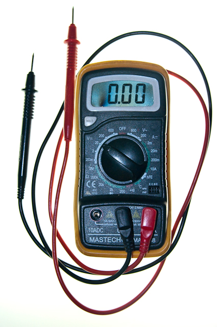
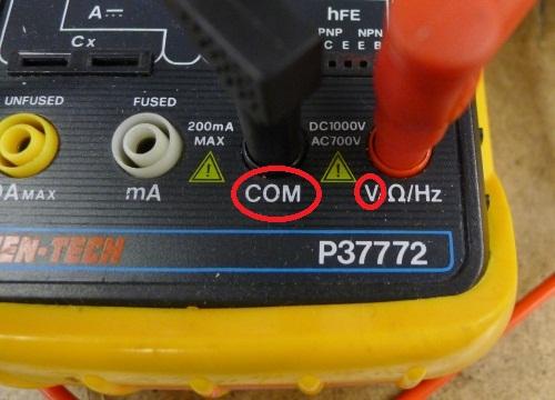
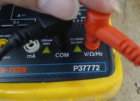
Insert the two probes. Insert the Black probe in the “COM” jack. This is the COMmon, or ground, connection. The Red probe should be in the “V” jack (Figure 11). This connection is for measuring voltage. It can also be used to measure resistance in Ohms, or frequency in megaHertz, on the meter shown here.
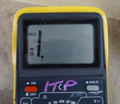
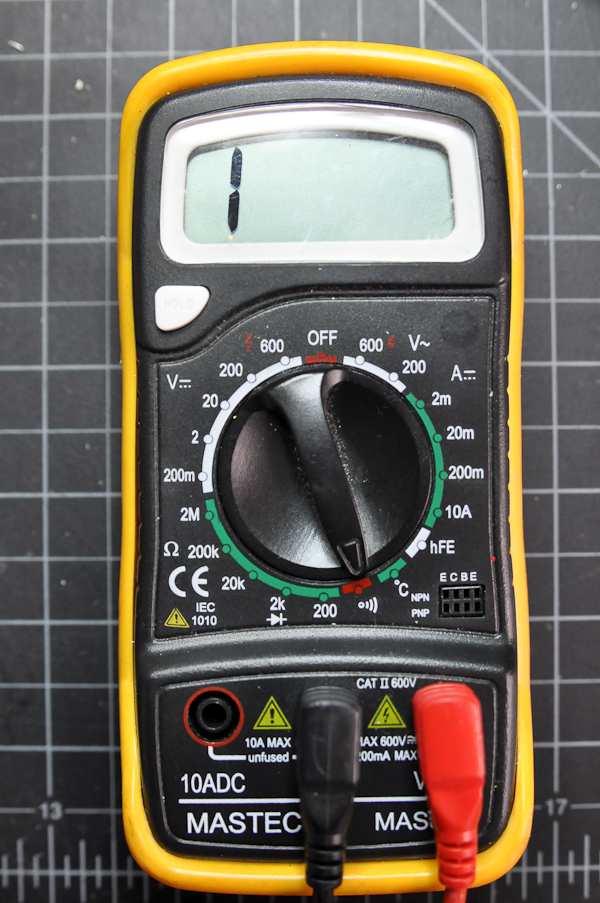
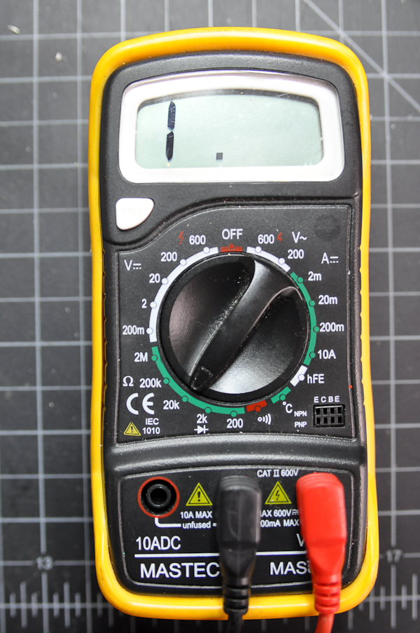
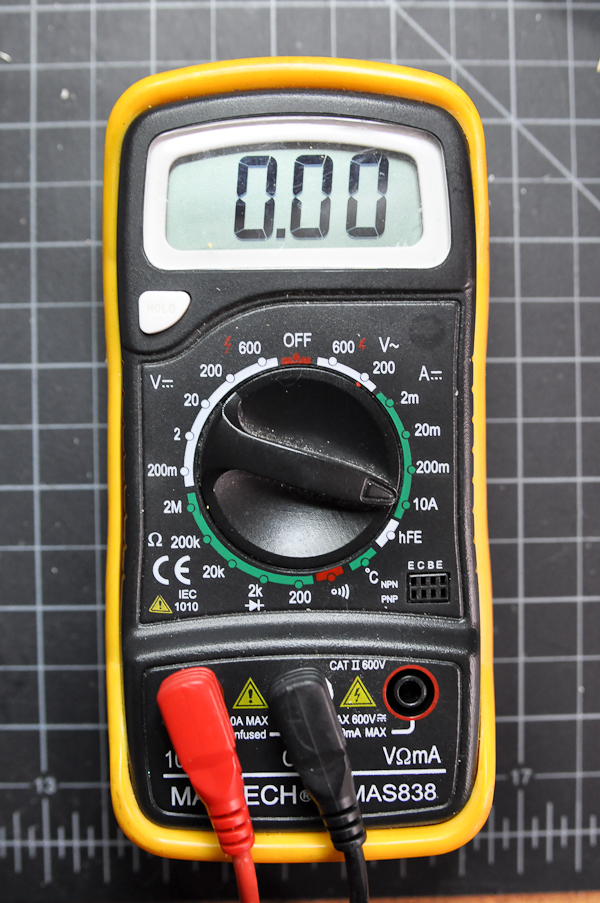
Turn the function knob to the Diode/Continuity Function and switch the meter on. If the word “Hold” appears on the screen, press the hold button once to disable the hold function (not all meters have a clearly labeled Hold function; check your meter’s manual to be sure – see Figure 12). This function is used to hold a value onscreen after you remove the probes from a circuit. The “1.” on left picture means the value is out of range now.
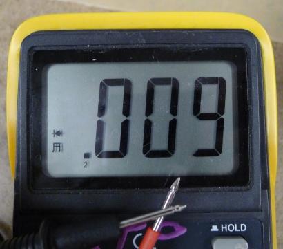
Touch the tips of the probes together. The meter will beep and the display value should be less than 0.01 (Figure 13). If it works, congratulations! you have a usable meter. If not, try to push the plug of the probes to improve the contacts (Figure 14). In many cases the failure is caused by loose contact of the jacks. In other cases, you might have a weak or dead battery.
The Controls on a Meter
Different meters have different controls, but most meters will have the following:
- Voltage: This setting is generally broken up into Volts DC, indicating that the polarity of the voltage will not change, and Volts AC, indicating that the polarity will alternate.
- Amperage: This setting measures the current in a circuit. Again, it’s usually broken up into AC and DC. There are commonly two holes for the positive probe to measure current, one that’s low amperage and the other that’s high amperage. Don’t try to measure high amperages with the positive probe in the low amperage hole or you will damage the meter.
- Resistance: Resistance is measured in ohms. This function is sometimes grouped with the continuity check.
- Continuity: Continuity measures for a connection, generally very low or no resistance.
- Diode Check: Diode check measures for a voltage drop across a diode, typically 2.7V or less. If you hold the positive probe on the anode of the diode and the common probe on the cathode, you’ll see a voltage drop. If you reverse the probes, you’ll see no reading.
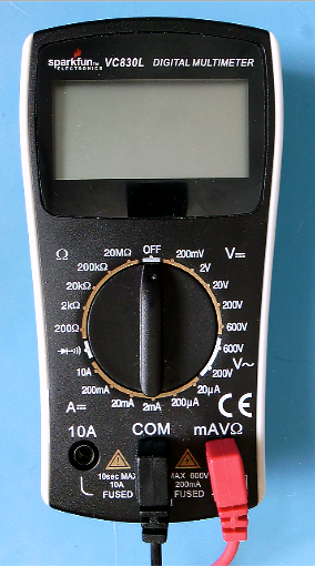
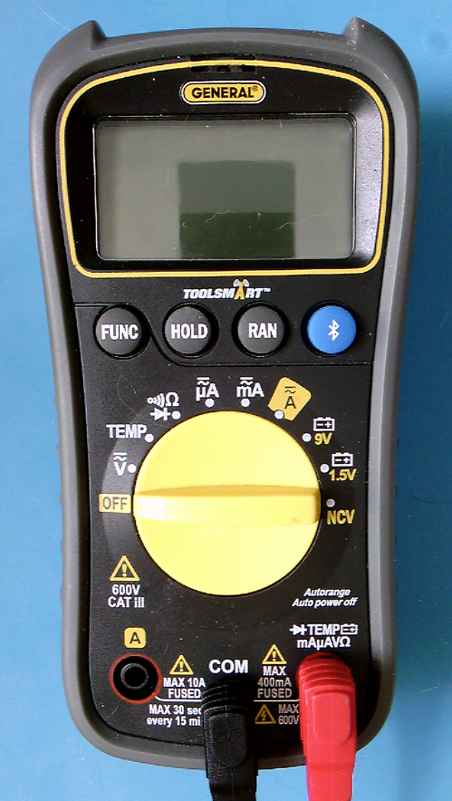
Some meters are auto-ranging, meaning that they will choose the right order of magnitude for a reading automatically. These meters will only have one setting for a given property (volts, ohms, amps, etc). Other meters are not auto-ranging. These meters will have multiple settings for a given property. For example, the meter in the next section below has multiple settings for the resistance (or ohms) property: 2M (megohms), 200k (kilohms), 20k, 2k, and 200 ohms.
Many meters will have additional functions, like temperature, capacitance, transistor checks, and more. The functions listed above are the minimum that you can expect, however.
Figures 15 and 16 show two multimeters. Figure 16 is autoranging and Figure 15 is not. Notice how the autoranging meter has only one setting per function, while the non-autoranging meter has several per function. For example, Voltage on the meter in Figure 15 is divided into AC (marked by a ~) and DC (marked by a ⎓). Within those two areas, there are multiple possible ranges: DC voltage can be set to 200mV, 2V, 20V, 200V, or 6ooV. Each range setting represents the maximum voltage you can read on that setting.
The Symbols on a Meter
Here are a few of the common symbols on electrical meters:
- Volts: V
- Ohms (resistance): Ω
- Amps (current): A
- AC: ~, ⏦ (tilde, sine wave)
- DC: ⎓
- Continuity: diode, speaker
- Diode Check:diode
- Non-Contact Voltage: NCV
- Ground: ⏚ (vertical line with three horizontal lines below it)
Measuring Continuity
Continuity is simply whether or not there is a connection between two points. You just used this function to test your meter (Figure 17). Now you’ll use it to test a conductor.
You can use the continuity check to find connections on a switch or if the pushbutton is connected when you press the button. You can also use it to measure whether there’s a break in a wire, or whether a given material conducts electricity. Set your meter as shown here, and try touching the probes together. The meter should beep.
Related video: Measure continuity with the Multimeter’s “beep”
Touching Two Ends of a Wire
Now try touching the probes to two ends of a wire. Again, the meter should beep. The wire conducts electricity. There is a continuous flow of electricity from one end of the wire to another.
Touching Two Points on a Switch
If you touch two points on a switch, what happens when you switch the switch? Beep or no beep? When you close the switch, the meter should beep, indicating that there is continuity between the two probes of the meter. If the meter beeps whether the switch is open or closed, then those two points are always connected.
Probing Points on a Breadboard
Put a wire in one hole of a breadboard that has no circuit on it. Then put another wire in another hole, chosen at random. Measure continuity between the two wires. Did you get what you expected? If the two holes were in the same row (or in the same column, on the side of the board) then you would get continuity and the meter would beep. If they were in different rows, then it would not beep.
Measuring Continuity Across Your Hand
Try measuring the continuity across your hand. Do you get anything? Why or why not? You probably don’t because the resistance across your skin is so high that it doesn’t register as a continuous conductor. It can conduct small amounts of current though. You don’t want your body to carry high amounts of current or voltage though, because it can damage or kill you.
Setup the Breadboard
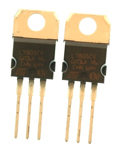
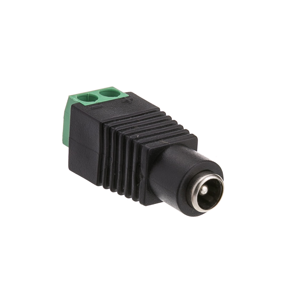
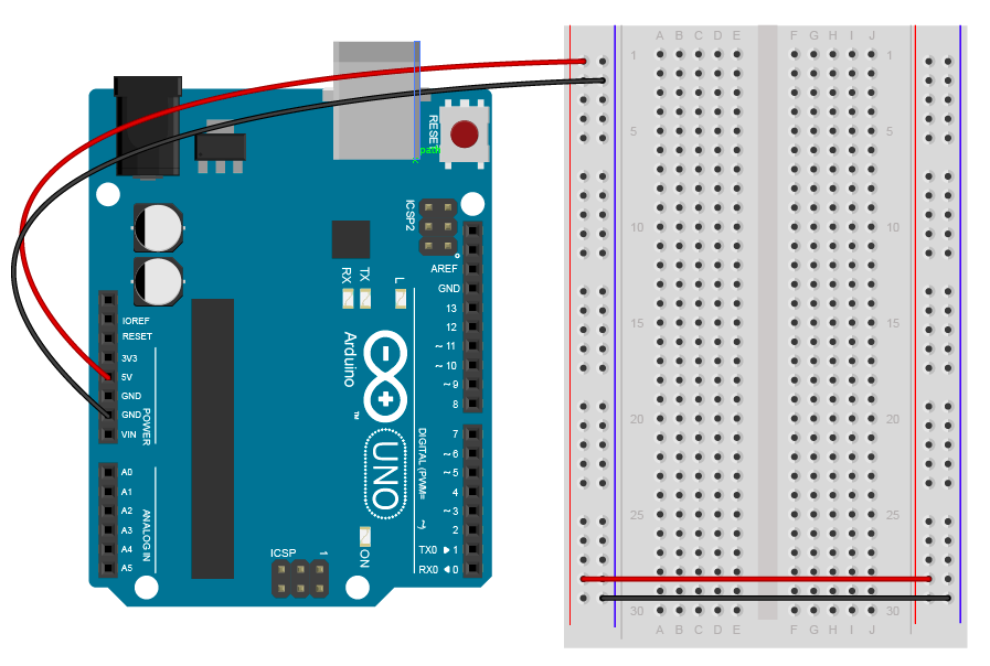
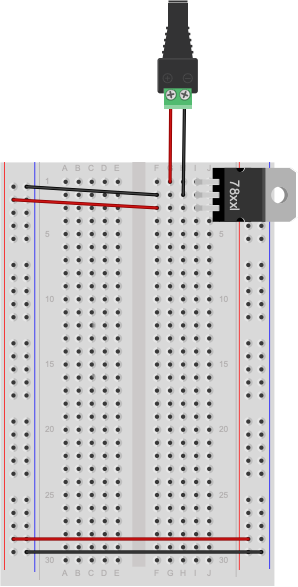
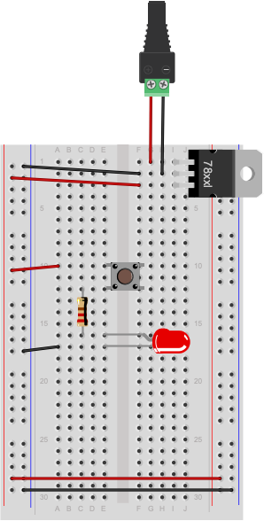
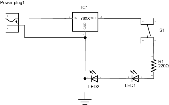
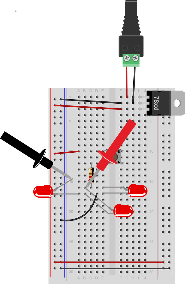
For the rest of this lab, you’ll need a breadboard connected to a +5 Volt or +3.3 volt power supply. You can use an Arduino as your power supply (Using Arduino Uno shown in Figure 18, using Arduino Nano shown in Figure 20), if it’s connected to a USB power supply or a DC power supply, or you can solder together a DC power jack as shown in the Soldering lab, and use a 9-12V DC power supply and a 7805 voltage regulator (Figure 19). The voltage regulator will take the DC power supply’s Voltage and regulate it down to 5 Volts DC.
If you are using a Nano for the first time, you might want to check out these videos before you get started, to prep your board and care for your microcontroller.
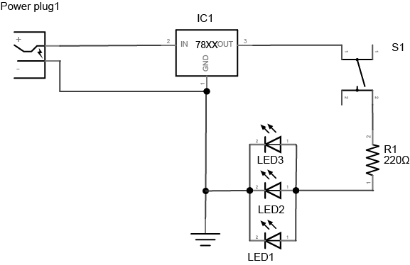
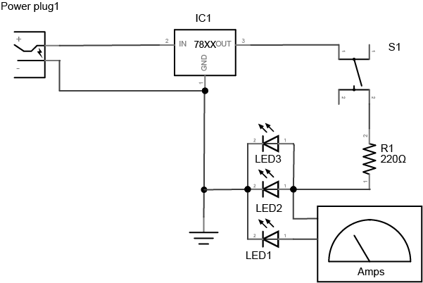
Note: Schematics
The diagrams to the left of some of the breadboard images in this exercise are called schematics.They show the electrical layout (as opposed to the physical layout) of the components. For a good rundown on reading and understanding schematics, see this page and some very useful videos on this topic in the videos section of this site.
Related video: Using a voltage regulator on a breadboard

From here on out, diagrams will show the DC power supply and voltage regulator version, but feel free to use the Arduino version instead if you prefer.
Measuring Resistance of a Component
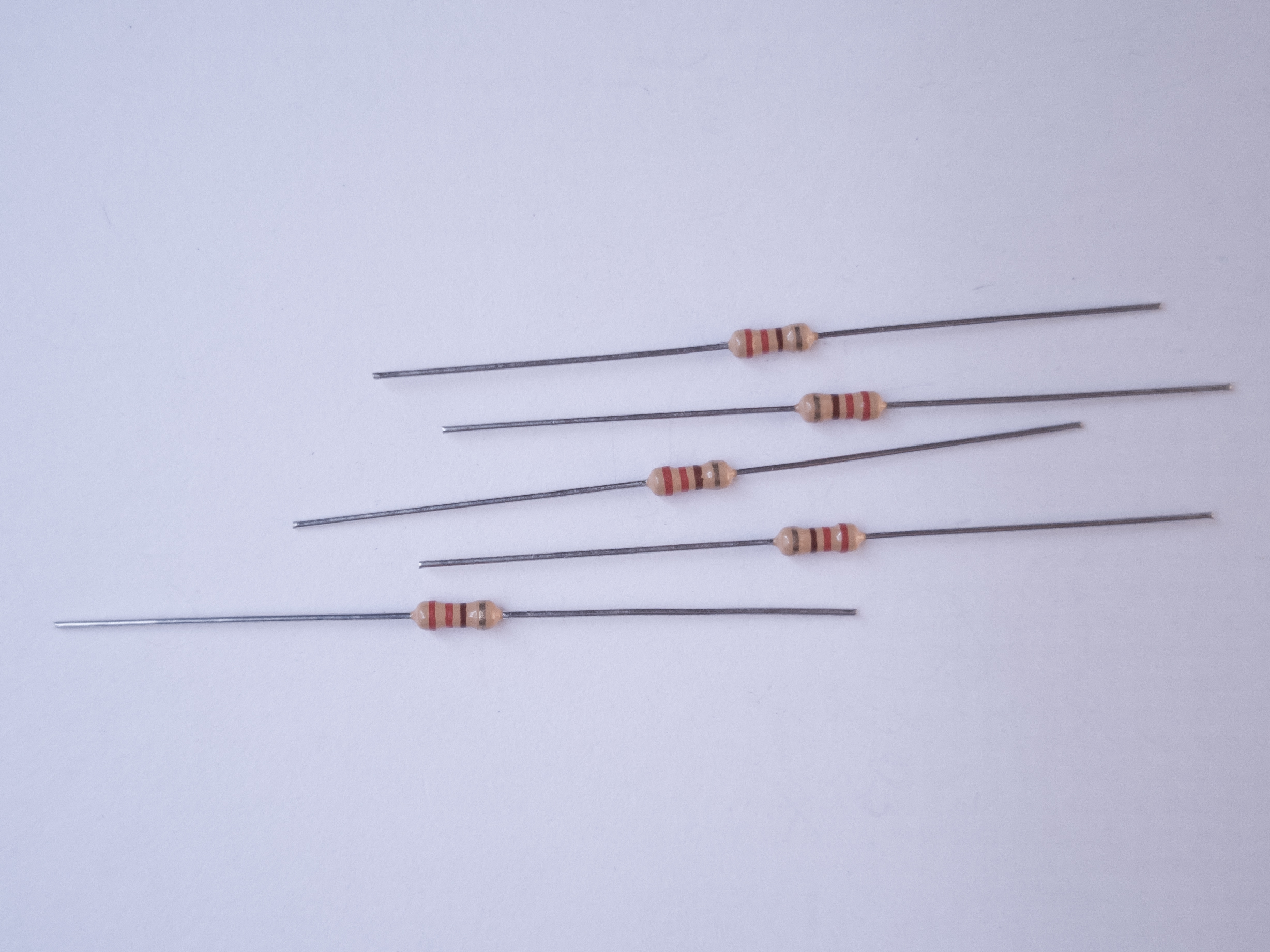
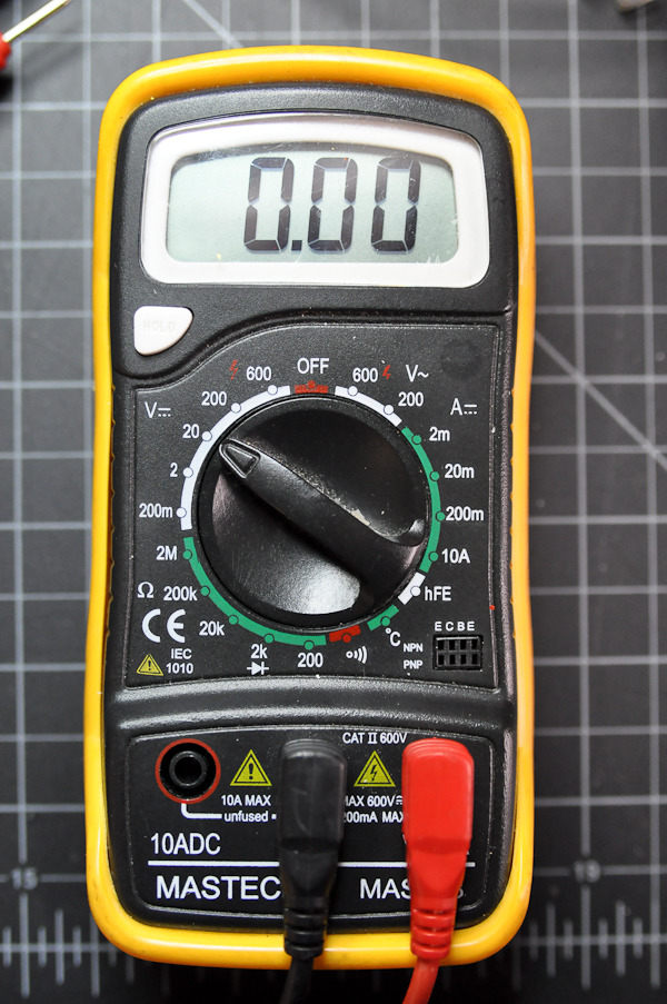
Resistance is a material property of any component, like a resistor or a wire. To measure the resistance of a component, you have to remove the component from the circuit. To measure resistance, turn your meter to the setting marked with the Greek letter Omega (Ω), as shown in Figure 21.
If your meter is not an auto-ranging meter, you want the meter set to the approximate range, and slightly higher than, of the component’s resistance. For example, to measure a 10-Kilohm resistance, you’d choose 20K, because 10K and 20K are in the same order of magnitude. For a 50K resistance, or anything over 20K, you’d have to step up to 200K. If you don’t know the component’s resistance, start with the meter set to a high reading, like 2M (2 Megohms). If you get a reading of zero, turn the meter one step lower, and keep doing so until you get a good reading. A reading of 1 on the left side of the meter, or of 0L, indicates you’re set to too low a range.
Related video: Measure resistance with a Multimeter
Not all components will register resistance. For example, a wire will ideally register 0 Ohms, because you want wires to have as little resistance as possible so they don’t affect the circuit. The longer the wire, the greater the resistance, however. Likewise, switches have ideally zero resistance.
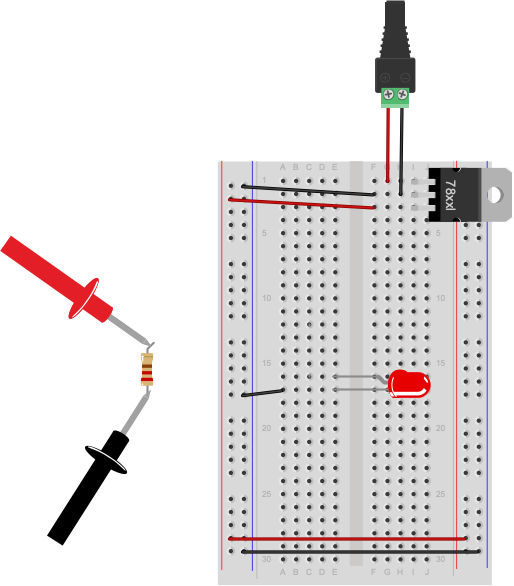
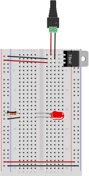
The circuit shown in Figure 22 is not complete. The resistor connecting the LED to voltage has been removed to measure its resistance. The resistor would normally connect in the row connecting to the red wire (row 12) to the anode of the LED (row 15). To measure resistance of a component, you must remove it from the circuit.
Resistance and Diodes
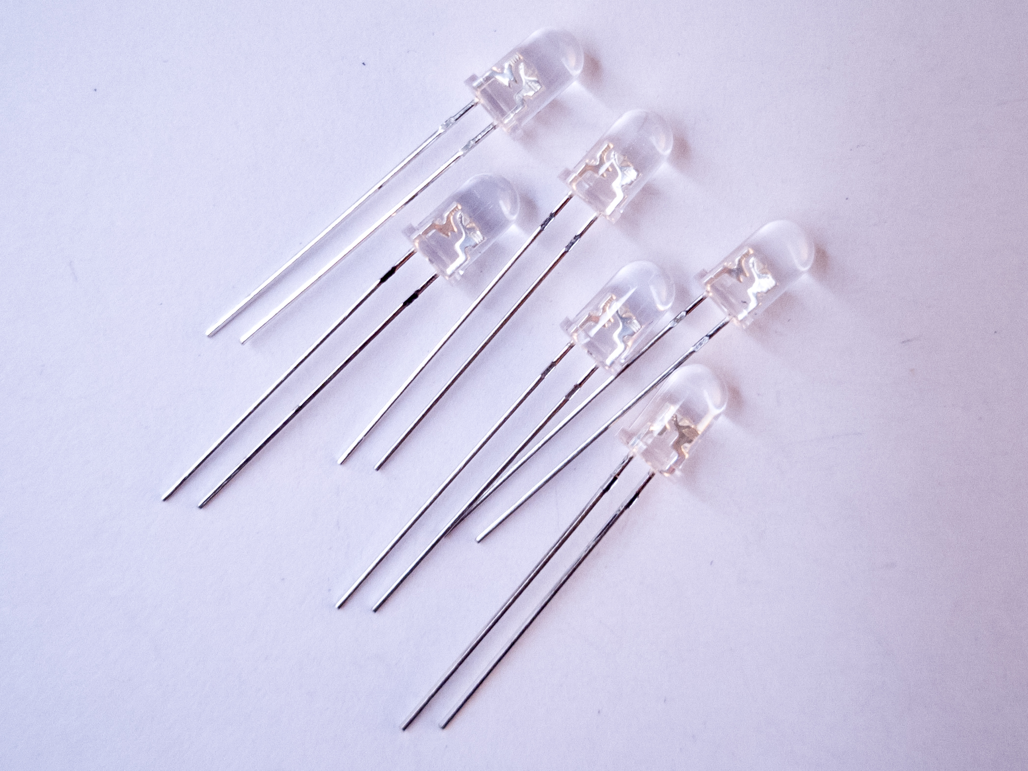
If you measure the resistance of a diode (such as the LED shown in Figure 20), you may see a number flash briefly on the meter, then disappear. This is because diodes ideally have little or no resistance once voltage is flowing through them, but have what’s called a forward bias, which is a minimum voltage needed to get current flowing. Before you reach the forward bias voltage, the diode’s resistance is ideally infinite. After you reach it, the resistance is ideally zero. There are no ideals in electronics, however, which is why you see a resistance value flash briefly as the meter meets the diode’s forward bias. Most meters have a diode check setting, marked with a diode symbol, that will allow you to check the forward bias of the diode.
Related video: Diodes and LEDs
Measuring Resistance Across Your Hand
Try measuring the resistance across your hand. Set the meter really high, perhaps 20 Megohms. Do you get anything? You should get a resistance in the 2-20 Megohm range. Make your palm sweaty, or lick it, and try again. You should get a lower resistance, perhaps 0.2 Megohms or so.
Measuring Voltage
Once a circuit is complete and powered, you should learn to read voltages between different points in the circuit. Wire a 7805 5-Volt voltage regulator on a breadboard as shown above and connect it to power. If you don’t have one, you can use the 5V or 3.3V output from an Arduino instead, as explained above. Now add an LED and a 220-ohm resistor to the breadboard as shown in Figure 23.
Note how the long leg, or anode, of the LED goes to voltage through the resistor, and the short leg, or cathode, goes to ground. Next you’re going to measure voltage in this circuit.
Voltage is a measure of the difference in electrical potential energy between two points in a circuit. It’s always measured between two points in a circuit. Measuring the voltage between the two sides of a component like an LED tells you how much voltage that component uses. When you’re measuring voltage between one side of a component and another, for example, it’s called measuring the voltage drop “across” the component.
Set your multimeter to measure DC volts (Figure 24). The voltage regulator you’re using can take an input voltage range of about 8 to 15 volts, and it outputs 5 volts, so you know that no voltage you’ll read in this circuit is over 15 volts. If your meter has a variety of ranges for DC volts, choose a range that ‘s closest to, and greater than, 15 volts. For example, many meters have a setting for 20 volts, meaning that they can read up to 20V DC at that setting.
Measure for voltage between the power and ground bus rows on the breadboard. You should have 5 volts, or very close to that.
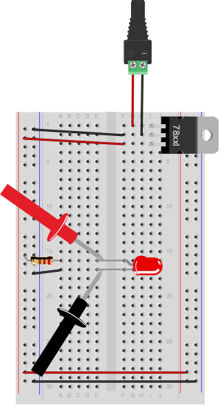
Now measure the voltage drop across the LED (Figure 25). When you’re measuring the voltage drop across a component, you put the meter probes in parallel with the component. In this case, the voltage across both the component and the meter will be the same.
Related video: Measuring voltage with a Multimeter
Getting a Negative Voltage
Did you get a negative voltage? Why would that happen? That means you placed the red probe on the point of lower voltage, and the black probe on the point of higher voltage. In other words, you reversed the polarity.
A Switched LED Circuit
Now you’re going to make a more complex circuit. Disconnect the board from power and add a switch in series with the LED and resistor as shown in Figure 26 and 27. Remember, long leg (anode) goes to voltage, short leg (cathode) goes to ground).
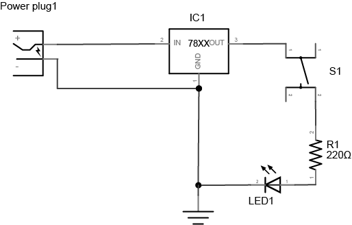
Connect the board to your power supply and press the switch. It will illuminate the LED. Let go of the switch and it will turn the LED off again. By pressing the switch you are completing a circuit and allowing the resistor and LED to begin consuming electricity. The resistor is very important in this circuit as it protects the LED from being over-powered, which will eventually burn it out. A typical LED operates at a voltage of 2.0-2.6 volts (V) and consumes approximately 20 milliamps (mA). The resistor limits the current to a level that is safe for the LED. The higher the resistor value, the less voltage that will reach the LED. The lower the resistor value (with 0 ohms being no resistor at all), the more the voltage that will reach the LED.
Adding Up Voltage
Now, while playing with the pushbutton, measure the voltage across the pushbutton as you did in the last step, both in the on position and the off position. Is there a voltage drop across the pushbutton? What voltage do you read when the pushbutton is not pressed?
Measure the voltage across the LED and the resistor as well. Does the total voltage across all the components add up to the voltage between voltage and ground on your board? Remember, in any circuit, all of the voltage must be used up. Why? If the voltage across all the components doesn’t add up, that indicates to you that some of the electrical energy is getting converted to light, heat, and other forms of energy. No component is 100% efficient, so there’s always the possibility for some loss.
Components in Series
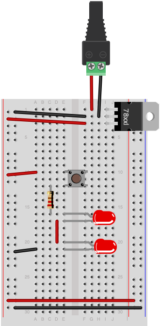
Change your circuit to add another LED in series with the first one, as shown in Figures 28 and 29.
Adding Up Voltage
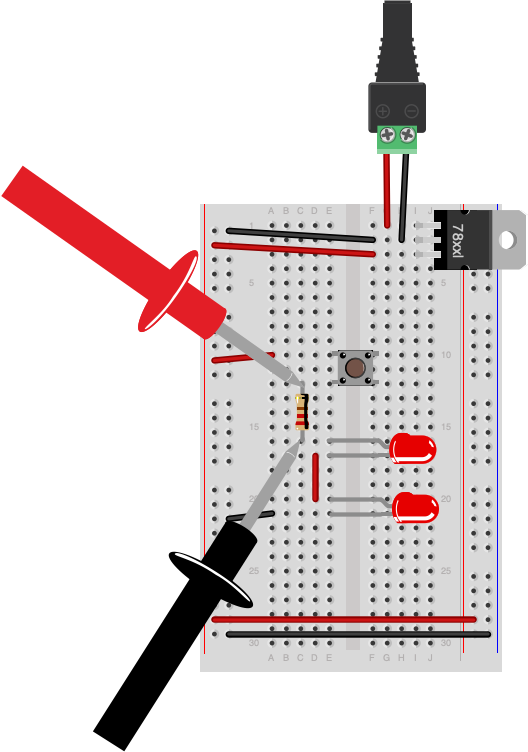
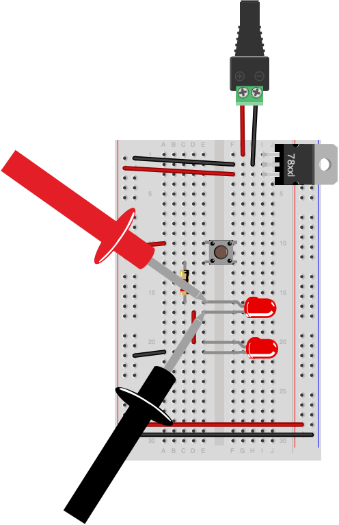
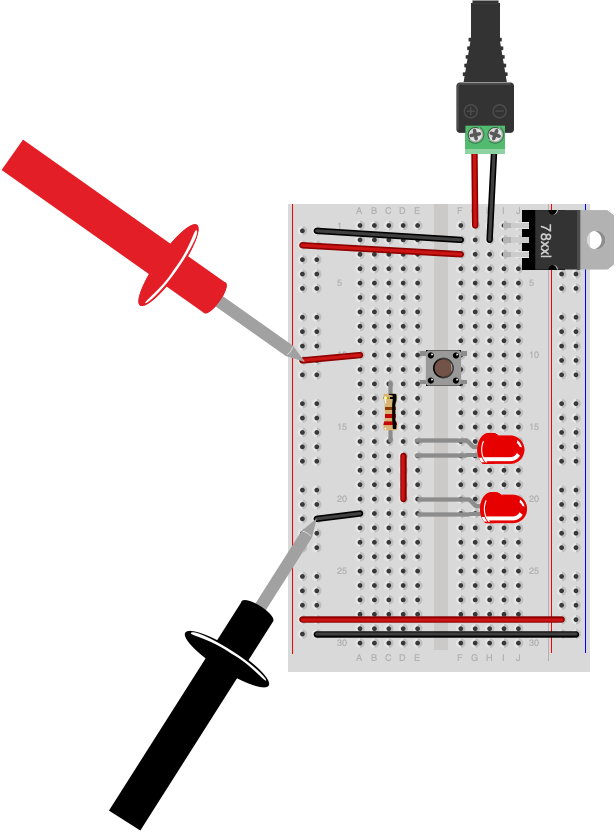
Measure the voltage across the resistor, as shown in Figure 30. Then measure the voltage across each LED, as shown in Figures 31 and 32. Does the total add up to the voltage from power to ground? If not, where does the missing voltage go? The remaining energy is lost as heat generated from the components.
Did you use two different color LEDs and get a different voltage drop across each one? That’s normal. Different color LEDs are made with different elements, and have slightly different voltage drops. Did you get no reading when you measured? Did you remember to push the button before you took your reading?
Adding a Third LED in Series
Add a third LED in series with the other two. Do the LEDs light? Why or why not? They most likely will not light up. Each LED needs about 2V to reach its forward bias and turn on. If you have three in series, and a 5-volt supply, each is getting less than the 2V it needs to turn on.
Components in Parallel/Measuring Amperage
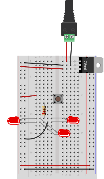
Connect three LEDs in parallel as shown in Figure 33 and 34 (remember, long leg (anode) goes to voltage, short leg (cathode) goes to ground):
Measure the voltage across each LED. It should be the same across each one.
Now you’re going to read the amperage at various points in the circuit. Move your meter’s red probe to the hole for measuring high amperage. On many meters, there are three holes, one marked “Volts/Ohms/mA”, and another marked “10A”. The right one can be used for measuring amperage when the expected amperage is less than 1A. The left is for measuring high amperage, up to 10A (Figure 35). If you’re not sure, it’s best to use the hole for 10A. Then set your meter to measure DC amperage.
To measure the amperage through a given component, you need to place your meter in series with the component. When two components are in series, the amperage flowing through both of them is the same. For this, use the circuit with the three parallel LEDs that’s shown in Figures 36 and 37. To measure the amperage through any one of the LEDs in this circuit, you’ll need to disconnect one of the LED’s ends from the circuit (disconnect power first!) and use the meter to complete the circuit, as shown in Figures 36 and 37:
You’ll find that the amperage drawn by the LEDs is tiny, on the order of 10 or 20 milliamps at the most. That’s normal for LEDs. Make sure that you check which holes your meter probes are connected to when you’re using a meter.
Warning: Measuring amperage with the red probe in the voltage hole when you have no idea how big the current is, or measuring voltage with it in the amperage holes is a good way to damage the meter.
Related video: Measuring amperage (current) with a Multimeter
Related video: Measure current in series, and voltage in parallel
Generating a Variable Voltage with a Potentiometer
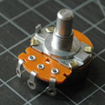
In this last step, you’ll generate a changing voltage using a potentiometer. A potentiometer is a resistor that can change its resistance. A potentiometer (or pot) has three connections. The outer connections are the ends of a fixed value resistor. The center connection connects to a wiper which slides along the fixed resistor. The resistance between the center connection and either of the outside connection changes as the pot’s knob is moved. Related video: Potentiometer schematic
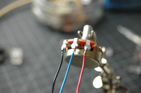
If your potentiometer does not have pins that will insert into a breadboard, then solder hook-up wires to the pot connections as shown in Figures 38 and 39.
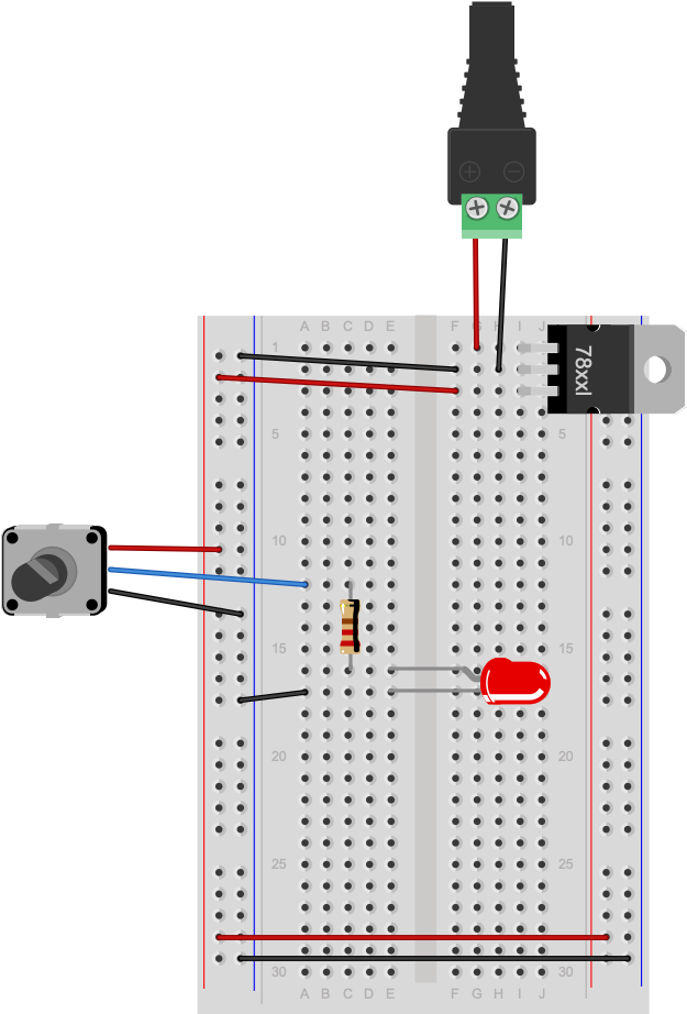
Next, connect the pot to an LED and a 220-ohm resistor using the circuit shown in Figure 38:
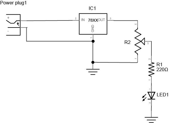
As you turn the potentiometer from one end to the other, measure the voltage between the center position and ground. The pot is acting as a voltage divider, dividing the 5V into two parts. As the voltage feeding the LED goes up or down, the LED gets brighter or dimmer. The 220-ohm resistor in the circuit protects the LED from over-voltage when the resistance between the pot’s voltage lead and its center lead is 0 ohms.
Related video: Measure a potentiometer’s variable resistance
Now you’ve got a basic understanding of how to use a meter to measure voltage, current, resistance, and electrical continuity. You’ll use these tests all the time.
Next, check out the lab on Switches.