Lab: Arduino and p5.js using a Raspberry Pi

For some applications, you only need a computer with an operating system in order to connect a serial device like an Arduino or other microcontroller with a browser-based multimedia application like p5.js. This page introduces how to do it using node.js, p5.serialserver, and a Raspberry Pi.

Introduction

For some applications, you only need a computer with an operating system in order to connect a serial device like an Arduino or other microcontroller with a browser-based multimedia application like p5.js. Perhaps you’re planning to run the sketch on a mobile device like an iPhone or Android device, but you need it to get data from sensors on your Arduino, or to be able to control motors or other outputs on the microcontroller. For these applications, an embedded Linux processor like a Raspberry Pi or BeagleBone can do the job well. By running an HTTP server and the p5.serialserver application from the Linux command line, you can make this happen. This page introduces how to do it using node.js, p5.serialserver, and a Raspberry Pi.

To get the most out of this tutorial, you should know what a microcontroller is and how to program microcontrollers. You should also understand asynchronous serial communication between microcontrollers and personal computers. You should also understand the basics of command line interfaces. It’s helpful to know a bit about the Raspberry Pi as well, and p5.js. If you’re looking for a Raspberry Pi setup that works on the networks at ITP, try this one. Finally, this tutorial on serial communication using node.js will give you a decent intro to node.js.

System Diagram

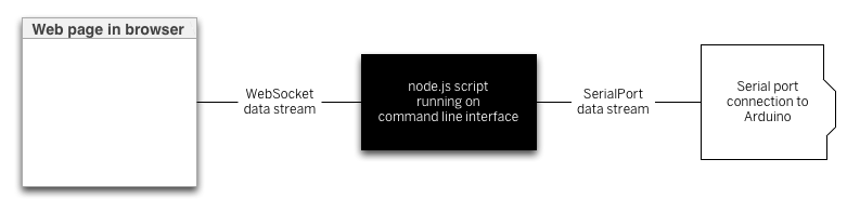
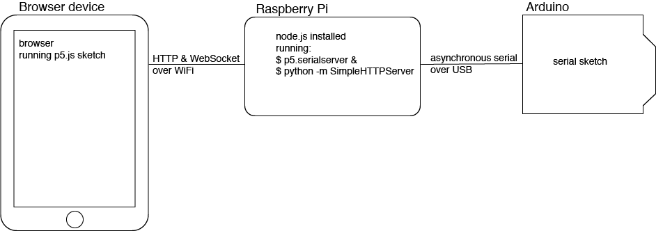
The system for this tutorial is as follows: your microcontroller is running a sketch that communicates using asynchronous serial communication, just like many of  the other serial tutorials on this site. It’s connected to an embedded Linux processor (a Raspberry Pi, in this case), which is running p5.serialserver, a command-line version of the p5.serialcontrol app used in the other p5.js serial tutorials on the site. The Pi is also running a Python-based HTTP server, which will serve your p5.js sketch and HTML page to any browser on the same network. The p5.js sketch uses the p5.serialport library to communicate back to p5.serialserver on the Linux processor in order to read from or write to the microcontroller’s serial port. The diagram below shows the system(Figure 1):

This is a system diagram that depicts the system described in the paragraph above. The browser device is on the left. The Raspberry Pi is in the center, and the Arduino is on the right.
Figure 1. Raspberry Pi serving p5.js files and running p5.serialserver

Node.js

The JavaScript programming language is mainly used to add interactivity to web pages. All modern browsers include a JavaScript interpreter, which allows the browser to run JavaScript code that’s embedded in a web page. Google’s JavaScript engine is called v8, and it’s available under an open source license. Node.js wraps the v8 engine up in an application programming interface that can run on personal computers and servers. On your personal computer, you run it through the command line interface.

Node was originally designed as a tool for writing server programs, but it can do much more. It has a library management system called node package manager or npm that allows you to extend its functionality in many directions. There is also an online registry of node libraries, npmjs.org. You can download libraries from this registry directly using npm. Below you’ll see npm used to add both serial communication functionality and a simple server programming library to node.

Install Linux, Node.js, and p5.serialserver

To get started, you’ll need to set up a Raspberry Pi for command line access. Follow this tutorial on how to set up the Rasberry Pi with th latest Raspbian distribution of Linux, with node.js and a firewall installed.

If you’ve never used a command line interface, check out this tutorial on the Unix/Linux command line interface.  From here on out, you’ll see the command prompt indicated like this:

yourlogin@yourcomputer ~$

Any commands you need to type will follow the $ symbol. The actual command prompt will vary depending on your operating system. On Windows, it’s typically this: >. On most Unix and Linux systems, including OSX, it’s $. Since this tutorial is only for Linux, look for the $.

Post-Install Checklist

Once you’ve installed everything from the previous tutorial, run the following commands on the command line of the Pi to make sure everything you need is installed. If you get the answers below, you’re ready to move on.

To check the version of the Raspbian distribution of Linux that you’re using, type:

$ lsb_release -a

You should get something like this or later:

No LSB modules are available.
Distributor ID: Raspbian
Description: Raspbian GNU/Linux 9.1 (stretch)
Release: 9.1
Codename: stretch

To get the versions of node.js,  npm, and iptables that you’re running, type (and get the replies below, or later):

$ node -v
v6.9.5

$ npm -v
3.10.10

$ sudo iptables --version
iptables v1.6.0

To check that your iptables firewall configuration is correct, type:

$ sudo iptables -S

You should get something like this, though your IP addresses for your router and gateway on lines 9 and 10 might be different:

-P INPUT ACCEPT
-P FORWARD ACCEPT
-P OUTPUT ACCEPT
-A INPUT -i lo -j ACCEPT
-A INPUT -i wlan0 -p tcp -m tcp --dport 80 -j ACCEPT
-A INPUT -i wlan0 -p tcp -m tcp --dport 443 -j ACCEPT
-A INPUT -i wlan0 -p tcp -m tcp --dport 8080 -j ACCEPT
-A INPUT -i wlan0 -p tcp -m tcp --dport 8081 -j ACCEPT
-A INPUT -s 192.168.0.1/32 -i tcp -p tcp -m tcp --dport 22 -j DROP
-A INPUT -s 192.168.0.0/24 -j ACCEPT
-A INPUT -m state --state RELATED,ESTABLISHED -j ACCEPT
-A INPUT -j REJECT --reject-with icmp-port-unreachable
-A FORWARD -j REJECT --reject-with icmp-port-unreachable

Get your Pi’s IP Address

It’s easy enough to run a simple HTTP server on your Pi, and then to use it to serve an HTML page with a p5.js sketch to any browser. First you’ll need to know your Pi’s IP address. You can get it like so:

$ sudo ifconfig wlan0 | grep inet

You’re using the ifconfig command to get the data on the wlan0 network interface. That’s your Pi’s WiFi radio. Then you’re passing the output from ifconfig to the grep program using a pipe (the | character). grep searches through the results for any line beginning with the string ‘inet’. Your result will look something like this:

inet 192.168.0.11 netmask 255.255.255.0 broadcast 192.168.0.255
inet6 2604:2000:c58a:da00:3b21:bed1:e1bb:8c3c prefixlen 64 scopeid 0x0<global>
inet6 fe80::52a3:f22:847f:7beb prefixlen 64 scopeid 0x20<link>

Your numbers will vary, but the one you want will be the four decimal numbers  following the first ‘inet’; 192.168.0.11 in the example above, but yours will be different depending on your network. That’s your IP address. Remember it, you’ll use it in a moment to browse files on your Pi.

Make a Simple Web Server on your Pi

To get your p5.js sketch and HTML page from the Pi, you’ll need to run a web server program. The installed version of the Python programming language includes one already. You need some content to serve. Make a p5.js project. You can download the p5.js example project. You can create all the files yourself, or you can download the files automatically using a command line tool called p5-manager. To install it, type:

$ sudo npm install -g p5-manager

This install might take awhile (45-70 minutes on a Pi Zero W), so take a break while it installs. When it’s installed, you can create a new p5 project anywhere like so:

$ p5 g -b myProject

This will generate (g -b stands for generate bundle) a directory called myProject containing all the files you need for a p5.js project. Change directories into your new project, then update your project’s p5.js files to the latest versions like so:

$ cd myProject
$ p5 update
p5-manager version 0.4.1
The latest p5.js release is version 0.5.16

The sketch.js file in this project doesn’t do anything, so you might want to edit it. You can edit it using the command line editor called nano like so:

$ nano sketch.js

You’ll get a full edit window like the one below, and you can move around the window with the arrow keys. Add the following lines to sketch.js’ draw() function:

1
2
3
4
5
function draw() {
    background('#3399FF');
    fill('#DDFFFF');
    ellipse(width / 2, height / 2, 50, 50);
}

To save the file, type control-X, then Y to confirm. The nano editor will quit and you’ll be back on the command line. Now run Python’s simpleHTTPServer like so:

sudo python -m SimpleHTTPServer 8080

You should get a reply like this:


Serving HTTP on 0.0.0.0 port 8080 ...

Now go to a web browser and enter your IP address from above like so: http://192.168.0.11:8080. You should see a page with a p5.js sketch in it like this(Figure2):

Screenshot of a p5.js sketch running in a browser. a light blue ball on a brilliant blue field fills the canvas of the sketch.
Figure 2. The p5.js serial sketch p5.js sketch running in a browser

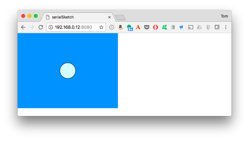
Congratulations, your Pi is now a web server! Now you’re ready to add the serial connection.  Type control-C to quit the SimpleHTTPServer.

Add node serialport and p5.serialserver

The next pieces to add are node’s p5.serialserver, which depends on the  node serialport library. The serialport library has to be downloaded and compiled natively for your processor. As the node serialport documentation explains, you’ll need to do it as shown here. You’re enabling unsafe permissions, and building from the source code.The unsafe permissions are needed to give your user account permission to access the /dev directory, in which serial port files live. You can do this all at once, by installing p5.serialserver with the same options, like so:

$ sudo npm install -g p5.serialserver --unsafe-perm --build-from-source

This install will take a long time, so again, take a break (60-90 minutes on a Pi Zero). Once it’s successfully installed, you’ve got all the pieces you need to serve serial-enabled p5.js sketches from your Pi, supplying the serial connection via the Pi’s serial ports.

The Raspberry Pi Serial Ports

There are a couple of ways you can access a serial port on the Pi. The GPIO port for the Pi includes a serial port on pins GPIO14 and GPIO15 (Figure 3.). This port is known as /dev/ttyS0 to the operating system.

The Raspberry Pi's GPIO pin diagram
The Raspberry Pi’s GPIO pin diagram.

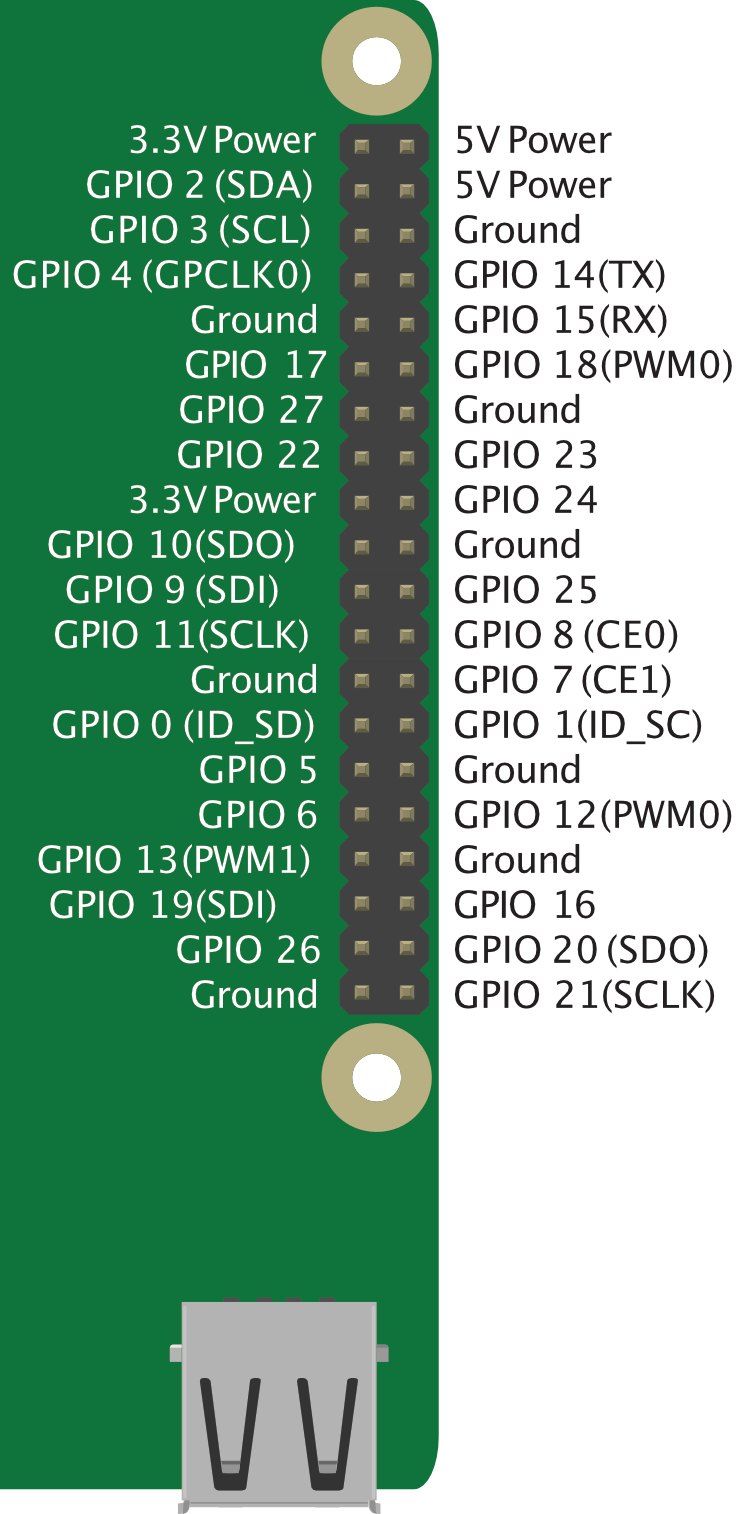
Table 1 below details the pin functions

Left SideRight Side
3.3V Power5V Power
GPIO 2 (SDA)5V Power
GPIO 3 (SCL)Ground
GPIO 4 (GPCLK0)GPIO 14 (TX)
GroundGPIO 15 (RX)
GPIO 17GPIO 18 (PWM0)
GPIO 27Ground
GPIO 22GPIO 23
3.3V PowerGPIO 24
GPIO 10 (SPI SDO)Ground
GPIO 9 (SPI SDI)GPIO 25
GPIO 11 (SPI SCLK)GPIO 8 (CE0)
GroundGPIO 7 (CE1)
GPIO 0 (ID_SD)GPIO 1 (ID_SC)
GPIO 5Ground
GPIO 6GPIO 12 (PWM0)
GPIO 13 (PWM1)Ground
GPIO 19 (SPI SDI)GPIO 16
GPIO 26GPIO 20 (SPI SDO)
GroundGPIO 21 (SPI SCLK)

If you’re connected to your Pi through a serial terminal connection, you’re going to have to give that up to talk to your microcontroller. To do that, first log out from the serial terminal and log in via ssh over a network connection. Once you’re logged in over the network, launch raspi-config:

$ sudo raspi-config

Pick option 5, interfacing options, and enable the serial port but disable the serial terminal. Save your choice, exit raspi-config, and restart your Pi:

$ sudo reboot

To get a list of your Pi’s ports, type the following:

$ ls /dev/tty*

You’ll get a long list, most of which are not your ports, and you’ll see the TTYS0 port toward the end. If you have an Arduino or other USB-to-serial device attached, you might see other ports marked TTYUSB0 as well. To determine which are the USB serial devices, run the ls command, then unplug the device, then run it again to see what disappears.

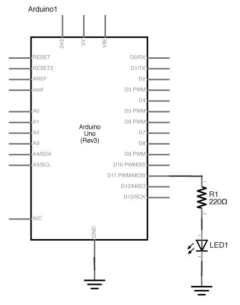
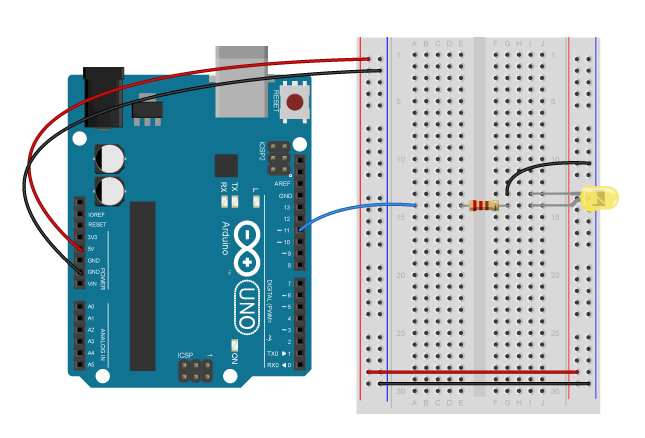
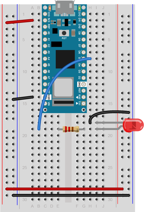
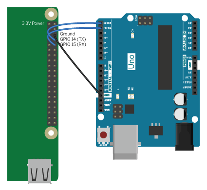
To connect a microcontroller to the GPIO serial port, attach the TX from your controller to the RX of the GPIO port and vice versa. Attach the ground of the GPIO port to the ground of your controller as well. The diagram below(Figure 4) shows the Pi connected to an Uno.

Pi to Uno configuration. Pi is connected to uno through ground pins, as well as, GP 14 (TX) to RX and GP 15(RX) to TX
Figure 4. Raspberry Pi connected serially to an Arduino Uno.

If you’re connecting to a Nano 33, MKRZero, MKR1000, Feather M0 Leonardo, Micro, or any of the boards based on the ARM M0 or ATMega 32U4, connect RX to TX and vice versa, but be aware that the RX and TX pins of those boards are addressed using Serial1 instead of Serial. For example, you’d call Serial1.begin(), Serial1.println(), and so forth.

You can also add serial ports as you would on a laptop, by plugging in a device that is compatible with a USB serial COM driver, like an Arduino. If you’re using a Pi Zero, you’ll need to use a USB-on-the-go adapter to connect to the Zero’s USB port.

The compatibility of your device will depend on the compatibility of the device’sUSB-to-serial chip. The official Arduino models comply with the USB standard serial COM protocol, and require no drivers. Third party and derivative models will vary depending on the hardware. If you want to avoid any driver issues and additional USB cables, use the GPIO serial port.

To test whether you’ve got control over the serial port, put a sketch on your microcontroller that sends out serial messages, like the AnalogReadSerial sketch in the Arduino Basics examples. Connect the controller to your Pi, and then use the cat command to read from the serial port like so:

$ cat /dev/ttyS0

You should see the serial data coming in just as you might in the Arduino Serial Monitor. If you do, you’re ready to build a full serial application. To quit cat, type control-C.

Making a Dynamic p5.serialport Sketch

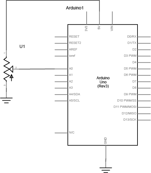
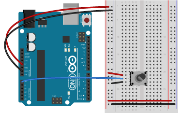
For background on p5.serialport, see the lab on serial input to p5.js.  To start with, you’ll need a microcontroller sending out serial data. Attach a potentiometer to pin A0 of your ArduinoStart, then with this basic handshaking sketch. Using handshaking (also sometimes called call-and-response) keeps the Pi’s serial buffer from getting full:

1
2
3
4
5
6
7
8
9
10
11
12
13
14
15
16
17
18
19
20
void setup() {
  Serial.begin(9600); // initialize serial communications
  while (!Serial.available()) { // until the server responds,
    Serial.println("Hello");    // send a hello message
    delay(500);                 // every half second
  }
}
 
void loop() {
  // if there are incoming bytes:
  if (Serial.available()) {
    // read incoming byte:
    int input = Serial.read();
    // read the input on analog pin 0:
    int sensorValue = analogRead(A0);
    // print out the value you read:
    Serial.println(sensorValue);
    delay(1); // delay in between reads for stability
  }
}
Schematic view of a potentiometer. First leg of the potentiometer is connected to +5 volts. The second leg connected to analog in 0 of the Arduino. The third leg is connected to ground.
Figure 5. Schematic view of a potentiometer connected to analog in 0 of the Arduino
Breadboard view of a potentiometer. First leg of the potentiometer is connected to +5 volts. The second leg connected to analog in 0 of the Arduino. The third leg is connected to ground.
Figure 6. Breadboard view of a potentiometer connected to analog in 0 of an Arduino

On the command line, create a new p5 sketch like so, then change directories to get into the sketch, then update the libraries:

$ p5 g -b serialSketch
$ cd serialSketch
$ p5 update

You’ll need the p5.serialport library to your sketch as well. You can copy it into the libraries directory like so:

$ sudo curl https://raw.githubusercontent.com/vanevery/p5.serialport/master/lib/p5.serialport.js --output libraries/p5.serialport.js

Once you’ve done that, edit the index.html file using nano as you did for the sketch.js above, and add a script include for libraries/p5.serialport.js in the HTML document’s head, before the script include for the sketch.js.

Save the file, then edit the sketch.js as follows:

1
2
3
4
5
6
7
8
9
10
11
12
13
14
15
16
17
18
19
20
21
22
23
24
25
26
27
28
29
30
31
32
33
34
35
36
37
38
39
40
41
42
var serial; // instance of the serialport library
var portName = '/dev/ttyS0'; // fill in your serial port name here
 
var circleSize = 50;
 
function setup() {
  createCanvas(320, 240);
  // initalize serialport library to connect to p5.serialserver on the host:
  serial = new p5.SerialPort(document.location.hostname);
  // set callback functions for list and data events:
  serial.on('list', printList);
  serial.on('data', serialEvent);
  // open the serial port:
  serial.open(portName);
}
 
function draw() {
  background('#3399FF');
  fill('#DDFFFF');
  // draw a circle at the middle of the screen:
  ellipse(width / 2, height / 2, circleSize, circleSize);
}
 
function serialEvent() {
  // read a line of text in from the serial port:
  var data = serial.readLine();
  console.log(data);
  // if you've got a valid line, convert it to a number:
  if (data.length > 0) {
    circleSize = int(data) / 4;
  }
  // send a byte to the microcontroller
  // to prompt it to respond with another reading:
  serial.write("x");
}
 
function printList(portList) {
  // portList is an array of serial port names:
  for (var i = 0; i < portList.length; i++) {
    console.log(i + ' ' + portList[i]);
  }
}

Note that when you’re calling new SerialPort();, you’re including a parameter, document.location.hostname. This is the address from which your sketch was served, in this case, your Pi. You can enter a specific IP address or domain name if you prefer, but document.location.hostname will always return the address of the server. This is the key to making your p5.serialport sketch dynamic, so it’s not locked to localhost.

At this point you have enough of a sketch to test the system. When loaded in a browser, this sketch should look like the one above, and should print the list of serial ports to the JavaScript console.

Run python’s SimpleHTTPServer a little differently this time:

$ python -m SimpleHTTPServer 8080 &

The & makes python return control to the command line so you can do other commands while it’s running. Hit the return key to get a command prompt again, then type:

$ p5serial

You should get this response:

p5.serialserver is running

Do as you did above, and open the sketch in a browser again. This time, open your JavaScript console and you should see the following output:

ws://192.168.0.12:8081
p5.serialport.js:83 opened socket
sketch.js:20 0 /dev/ttyAMA0
sketch.js:20 1 /dev/ttyS0

You should also see the serial data coming in from the microcontroller, and if you turn the potentiometer, you should see the circle size change. If you get this, do a happy dance. You’ve got a working p5.serialserver system working.

To quit p5.serialserver, type control-C. To stop the SimpleHTTPServer, type the following to get a list of the running processes:

$ ps
PID TTY TIME CMD
785 pts/0 00:00:02 bash
8186 pts/0 00:00:00 python
8203 pts/0 00:00:00 ps

This is a list of all running user-started processes and their process numbers. The python SimpleHTTPServer is number 8186 above. To stop it, type:

$ kill 8186

with your own process number, and python will stop. In the future, you can run p5serial this way as well, to get the command line control back while it’s still running.

Once you’ve got this much working, all the same dynamics of serial communication that apply on your desktop also apply on the Pi. Only one program at a time can control the port. Both sides need to agree on electrical connections, timing, and data format. Handshaking can help manage traffic flow. The troubleshooting techniques you used in desktop serial apply here also.

The Pi isn’t perfect as a multimedia host for all projects. It’s not as good on graphics as even the most basic desktop computer, for example. It’s great as a network connector like this, though, and it’s great to serve browser-based content that needs to connect to a serial port.

For more info:

Lab: Serial Input to an Arduino from Node.js

In this lab, you’ll send asynchronous serial data from your personal computer to an Arduino microcontroller in order to control a digital output of the microcontroller. Once you’ve done that, you’ll also learn how to interpret ASCII-encoded numeric strings on the Arduino.

Introduction

In this lab, you’ll send asynchronous serial data from your personal computer to an Arduino microcontroller in order to control a digital output of the microcontroller. Once you’ve done that, you’ll also learn how to interpret ASCII-encoded numeric strings on the Arduino.

These videos will help to understand this lab:

The current version of this lab works with version 6.x.x of the node-serialport library.

What You’ll Need to Know

To get the most out of this Lab, you should be familiar with the basics of programming an Arduino microcontroller. If you’re not, review the Digital Input and Output Lab, the Serial Output from an Arduino Lab, and perhaps the Getting Started with Arduino guide.

The video Video: Serial 3 – DIY Protocol covers the same material as this lab.

Things You’ll Need

Figure 1-3 are basically what you need for this lab.

Photo of an Arduino Nano 33 IoT module. The USB connector is at the top of the image, and the physical pins are numbered in a U-shape from top left to bottom left, then from bottom right to top right.
Figure 1: Arduino Nano 33 IoT
Three short pieces of hookup wire: one is clad in red insulation, one in blue, and one in black. All three have exposed ends approximately 5mm long.
Figure 2: 22AWG hookup wire
LEDs. Shown here are four LEDs. The one on the right is an RGB LED. You can tell this because it has four legs, while the others have only two legs.
Figure 3: LEDs. Shown here are four LEDs. The one on the right is an RGB LED. You can tell this because it has four legs, while the others have only two legs.

Prepare the breadboard

Connect power and ground on the breadboard to power and ground from the microcontroller. On the Arduino module, use the 5V and any of the ground connections(Figure 4):

An Arduino Uno on the left connected to a solderless breadboard, right. The Uno's 5V output hole is connected to the red column of holes on the far left side of the breadboard. The Uno's ground hole is connected to the blue column on the left of the board. The red and blue columns on the left of the breadboard are connected to the red and blue columns on the right side of the breadboard with red and black wires, respectively. These columns on the side of a breadboard are commonly called the buses. The red line is the voltage bus, and the black or blue line is the ground bus.
Figure 4: An Arduino Uno on the left connected to a solderless breadboard, right.
Arduino Nano on a breadboard.
Figure 5. Breadboard view of Arduino Nano on a breadboard.

As shown in Figure5, the +3.3 volts and ground pins of the Arduino are connected by red and black wires, respectively, to the left side rows of the breadboard. +3.3 volts is connected to the left outer side row (the voltage bus) and ground is connected to the left inner side row (the ground bus). The side rows on the left are connected to the side rows on the right using red and black wires, respectively, creating a voltage bus and a ground bus on both sides of the board.


Add the LED

Related Video: DIY Serial protocol

Connect an LED and resistor to pin 11 of the Arduino through a 220-ohm resistor. If you prefer an audio output, you can use a speaker instead. Appropriate code changes will be mentioned below (Figure6-7):

Schematic view of an Arduino connected to an LED. Digital pin 5 is connected to a 22-ohm resistor. The other side of the resistor is connected to the anode (long leg) of an LED. The cathode of the LED is connected to ground.
Figure 6: Schematic view of an Arduino connected to an LED.
Breadboard view of an Arduino connected to an LED. The +5 volts and ground pins of the Arduino are connected by red and black wires, respectively, to the left side rows of the breadboard. +5 volts is connected to the left outer side row (the voltage bus) and ground is connected to the left inner side row (the ground bus). The side rows on the left are connected to the side rows on the right using red and black wires, respectively, creating a voltage bus and a ground bus on both sides of the board. A blue wire connects Digital to a 22-ohm resistor that straddles the center divide of the breadboard in row 17. The other side of the resistor is connected to the anode (long leg) of an LED. The LED is mounted in rowsd 16 and 17 of the right side of the center section of the board. a black wire connects the cathode's row, row 16, to the ground bus on the right side of the board.
Figure 7: Breadboard view of an Arduino connected to an LED.

Breadboard view of an LED connected to digital pin 5 of an Arduino Nano.
Figure 8. Breadboard view of an LED connected to digital pin 5 of an Arduino Nano.

Figure 8: Breadboard view of an LED connected to digital pin 5 of an Arduino Nano. The Nano straddles the center of the breadboard in the first fifteen rows. The Nano’s voltage pin (physical pin 2) connects to the board’s voltage bus, and the Nano’s ground pin (physical pin 14) connects to the board’s ground bus. The LED is in the right center of the board, with its anode in one row and the cathode in the next. A 220-ohm resistor connects the LED’s anode to a wire connecting to digital pin 5. The LED’s cathode is connected to the ground bus.


Program the Microcontroller to Read Serial Input

Related Video: Serial.available()
To program the Arduino to read serial input, you use the Serial.available() command. The .available() command returns the number of bytes that are available in the Arduino’s serial buffer that you haven’t read yet. When there are bytes available, you can read them using Serial.read().

In the setup() function of your program, initialize serial communications using Serial.begin(). Set the LED’s pin to be an output using pinMode() as well. Then in the setup, check how many bytes are available in the serial buffer using Serial.available() like so:

1
2
3
4
5
6
7
8
9
10
void setup() {
  Serial.begin(9600);   // initialize serial communications
  pinMode(11, OUTPUT);  // set digital pin 11 to be an output, to control the LED
}
 
void loop() {
  if (Serial.available() > 0) {
 
  }
}

Interpret the Incoming Serial Bytes

Related Video: reading the bytes in Arduino
Inside the if statement that checks Serial.available(), you’ll interpret the bytes as they come in. First, read the incoming bytes using Serial.read(). The serial buffer is a First-in, First-out buffer, or a FIFO buffer, meaning that the first byte that the computer sends is the first byte that the Arduino can read:

Here’s how to read the incoming bytes and interpret them:

1
2
3
4
5
6
7
8
9
10
11
void loop() {
  if (Serial.available() > 0) {
    byte input = Serial.read();  // read first available byte into a variable
    if (input == 'H') {          // if the variable equals H, or ASCII 72
      digitalWrite(11, HIGH);     // turn on the LED
    }
    if (input == 'L') {          // if the variable equals L, or ASCII 76
      digitalWrite(11, LOW);      // turn off the LED
    }
  }
}

This sketch now reads the first available byte  into the variable input, then evaluates the variable. If input is equal to 72, which is the ASCII letter H, it turns on the LED. If input equals 76, or ASCII L, it turns the LED off.

Note: What Do the Single Quotes Mean?

In the C programming language (and by extension, in Arduino, since Arduino based on C), you can put a single ASCII character in single quotes and the compiler will interpret it as its numeric value. This can be handy when you know you want to compare a byte to an ASCII character, but can’t remember the numeric value of the ASCII character.

Send Bytes to the Microcontroller

Related Video: uploading the sketch to the Arduino

Once you’ve uploaded this to the board, open the serial monitor. If you’re using the Arduino Serial Monitor to read and write serial data, make sure the line ending tab is set to “no line ending” like so(Figure 9):

Screenshot of the Arduino IDE Serial Monitor line ending option. The "no line ending" option is chosen.
Figure 9: Screenshot of the Serial Monitor line ending option

If you prefer to use a command line interface for serial communication, you can do that using the screen command.

Type H or L in the text input bar at the top, then hit enter. You should see the LED turn on when you send H, and turn off when you send L. You’ll notice that if you send lower case h or l, nothing happens. That’s because you didn’t check for those values. In ASCII, uppercase letters and lowercase letters each get different values. Uppercase H is 72, for example, but lowercase h is 104.

The serial monitor isn’t the only program that can send bytes to your microcontroller. Any program that can communicate over asynchronous serial communication can be used to send data. So if you’re using Processing, or Max/MSP, or node.js, you can control this simple Arduino program serially.

Change the Brightness of the LED Bytes Serially

The microcontroller reads all incoming bytes as values from 0 to 255. In the example above, you saw how to interpret those values as ASCII characters. But you can use the byte values any way you wish. Change the loop of your program as shown below:

1
2
3
4
5
6
7
8
void loop() {
  // put your main code here, to run repeatedly:
  if (Serial.available() > 0) {
    byte input = Serial.read();
    // use the value of the incoming byte to control the LED's brightness:
    analogWrite(11, input);
  }
}

Upload this new sketch and open the serial monitor. When you send characters now, what’s happening? The LED’s brightness might be jumping around, seemingly randomly.  Lower case letters toward the end of the alphabet will make the LED slightly brighter, and uppercase ones toward the beginning will make it dimmer. The lower the value, the lower the brightness of the LED. a space, which is ASCII 32, will make the LED very dim, while a tilde (~), which is ASCII value 126, will make it brighter.

Related Video: reading a byte from the computer in Arduino

Advanced Serial Input: Parsing Numeric Strings

But what if you want to send an ASCII-encoded numeric string?  Why doesn’t the LED turn on to full brightness when you type “255”?  Even though you interpret the characters as one number, the Arduino interprets them as three bytes, with the values 50 (“2” = ASCII 50), 53 (“5” = ASCII 53), and 53. How do you get the Arduino to convert these strings as numbers?

You can use the Serial.parseInt() function to interpret ASCII numeric strings. This function will read all incoming bytes looking for a numeric character, and when it finds one, it will keep looking until it finds the next non-numeric character. Then it will interpret all the numeric characters it found as one number. Change your sketch’s loop as follows:

1
2
3
4
5
6
7
8
void loop() {
  // put your main code here, to run repeatedly:
  if (Serial.available() > 0) {
    int input = Serial.parseInt();
    // use the value of the incoming byte to control the LED's brightness:
    analogWrite(11, input);
  }
}

Then send in a numeric string, like 255 or 10. You should see the LED get much brighter with 255, and much dimmer with 10. If you send 0, the LED should turn off. Instead of interpreting your data byte-by-byte, .parseInt() is looking for strings of numbers and interpreting them. You can even give it multiple strings separated by non-numeric characters. Try the following strings:

10,127,255 0 255 0 12-250-3

You can separate your numbers however you wish. You could even look for multiple different numbers with multiple variables, like this:

1
2
3
4
5
6
7
8
void loop() {
  // put your main code here, to run repeatedly:
  if (Serial.available() > 0) {
    int red = Serial.parseInt();
    int green = Serial.parseInt();
    int blue = Serial.parseInt();
  }
}

With the code above, if you sent three comma-separated values, you’d be able to set the three variables red, green, and blue independently.

Serial.setTimeout()

You may notice that .parseInt() is slow to respond. It has a timeout that defaults to one second, waiting for incoming data. You can speed it up by using Serial.setTimeout() to set the timeout in milliseconds. In your setup, right after Serial.begin(), try a Serial.setTimeout(10) to set the timeout to 10 milliseconds. This is generally good for most programs that might be sending ASCII strings to the microcontroller.

Serial Control from Node.js

If you’re familiar with node.js and the node-serialport library, perhaps because you’ve already tried the Serial to node.js lab, upload the following Arduino sketch:

1
2
3
4
5
6
7
8
9
10
11
12
13
14
15
void setup() {
  // put your setup code here, to run once:
  Serial.begin(9600);
  Serial.setTimeout(10);
  pinMode(11, OUTPUT);
}
 
void loop() {
  // put your main code here, to run repeatedly:
  if (Serial.available() > 0) {
    char input = Serial.parseInt();
    // use the value of the incoming byte to control the LED's brightness:
    analogWrite(11, input);
  }
}

Now try the following node.js script (you’ll need to install node-serialport using npm as you did in the Serial to node.js lab). Save this as serialOutput.js:

1
2
3
4
5
6
7
8
9
10
11
12
13
14
15
16
17
18
19
20
21
22
23
24
25
26
27
28
29
30
// serial port initialization:
var SerialPort = require('serialport'); // include the serialport library
var portName = process.argv[2]; // get the port name from the command line
var myPort = new SerialPort(portName, 9600);// open the port
 
// these are the definitions for the serial events:
myPort.on('open', openPort); // called when the serial port opens
 
function openPort() {
  var brightness = 0; // the brightness to send for the LED
  console.log('port open');
  console.log('baud rate: ' + myPort.options.baudRate);
 
  // since you only send data when the port is open, this function
  // is local to the openPort() function:
  function sendData() {
    // convert the value to an ASCII string before sending it:
    myPort.write(brightness.toString());
    console.log('Sending ' + brightness + ' out the serial port');
    // increment brightness by 10 points. Rollover if < 255:
    if (brightness < 255) {
      brightness+= 10;
    } else {
      brightness = 0;
  }
}
 
// set an interval to update the brightness 2 times per second:
setInterval(sendData, 500);
}

Make sure the serial monitor in Arduino is closed, then run this by typing the following on the command line:

$ node serialOutput.js portname

Replace portname with the name of your serialport. When this runs, you should see the LED getting ten percent brighter every half a second, then go out when it reaches the brightest.

Lab: Serial Communication with Node.js

In this lab you’ll connect a microcontroller to a web browser using the node.js programming environment, HTML, and JavaScript.

Introduction

You can write programs that handle serial communication in many different languages. This page introduces how to do it using node.js. Node is a JavaScript environment that allows user to write web server programs. Below, you’ll use it to connect a microcontroller to a web browser using the node.js programming environment, HTML, and JavaScript.

To get the most out of this tutorial, you should know what a microcontroller is and how to program a microcontroller. You should also understand asynchronous serial communication between microcontrollers and personal computers. You should also understand the basics of command line interfaces.

You will struggle with this tutorial if you aren’t familiar with JavaScript.  For more on JavaScript, see Douglas Crockford’s JavaScript: The Good Parts, Manuel Kiessling’s  the Node Beginner Book, or Shelley Powers’ Learning Node.

The current version of this tutorial works with version 6.x.x of the node-serialport library.

This node.js introductory video will help in understanding this lab. The code in the video is different than this lab, but the basic concepts are similar. This lab simplifies the process a bit.

Node.js

The JavaScript programming language is mainly used to add interactivity to web pages. All modern browsers include a JavaScript interpreter, which allows the browser to run JavaScript code that’s embedded in a web page. Google’s JavaScript engine is called v8, and it’s available under an open source license. Node.js wraps the v8 engine up in an application programming interface that can run on personal computers and servers. On your personal computer, you run it through the command line interface.

Node was originally designed as a tool for writing server programs, but it can do much more. It has a library management system called node package manager or npm that allows you to extend its functionality in many directions. There is also an online registry of node libraries, npmjs.org. You can download libraries from this registry directly using npm. Below you’ll see npm used to add both serial communication functionality and a simple server programming library to node.

To get started, download the node.js installer and install it on your computer. Then open your command line terminal. On OSX, open the Terminal app, which can be found in the Applications/Utilities directory. On Windows, go to the start menu and type cmd then press enter to open a window to the command line.

If you’ve never used a command line interface, check out this tutorial on the Unix/Linux command line interface.  From here on out, you’ll see the command prompt indicated like this:

yourname@yourcomputer ~ $

Any commands you need to type will follow the $ symbol. The actual command prompt will vary depending on your operating system. On Windows, it’s typically this: >. On most Unix and Linux systems, including OSX, it’s $ or %.

When you’ve installed node.js, type this command at the command prompt to get the version of node that you’re running:

$ node -v

If you installed it correctly, you’ll get a version number like 12.18.0. The node installer should also install the node package manager (npm). You can check that in the same way:

$ npm -v

Once node and npm are in place, you’re ready to create a new project.

Related video: Install the serialport Node module

Hello from Node.js

There’s a library for node.js that allows you to communicate over your computer’s serial ports called serialport. If your computer’s connected to the internet, you can download install it automatically using npm. Create a new directory for your project:

$ mkdir nodeSerialExample

Then change directories to that directory:

$ cd nodeSerialExample


Now make a new text file in that directory with the name index.js.

This will be your main program file.  Add the following text to the file:

1
console.log("Hello, and welcome to node.");

Save the file, then run it by typing the following on the command line:

$ node index.js

Your program should print out:

Hello, and welcome to node.

The program will finish and return to the command line when it’s done. Seeing that script running is indication that node.js is fully working on your machine.

You can also pass information into your node program using the process arguments on the command line.  Change your program like so:

1
2
var name = process.argv[2];
console.log("Hello, and welcome to node," + name);

Run this as you did before, but add your name after the name of your program when you invoke it, like so:

$ node index.js Tom

You’ll get the following:

Hello, and welcome to node, Tom

The command line arguments are passed to your program as an array. The name was the third word you typed, or array element 2 (counting “node” as element 0 and “index.js” as element 1).  This is a useful technique, and you’ll see it later to pass the program your serial port’s name.

The Node Serialport Library

You’ll also need the node serialport library, which you can install from the npm registry like so:

$ npm install serialport

This command will make a new subdirectory called node_modules, and in that directory it will install all the necessary assets for the serialport library.  You’ll see a lot of text go by, and hopefully no errors. If you get errors, consult npmjs.org and the github wiki for serialport. Now you’re ready to use the serialport library.

The first thing you’ll want is a list of the serial ports. Replace the text of your program file with the following:

1
2
3
4
5
6
7
let serialport = require('serialport');
 
// list serial ports:
serialport.list().then (
  ports => ports.forEach(port =>console.log(port.path)),
  err => console.log(err)
)

Note: What’s With This Crazy Syntax?

If you’re new to JavaScript, this syntax may be confusing. Node.js examples tend to use anonymous functions frequently. JavaScript can pass functions as variables (and vice versa).  This is also using the JavaScript ES6 arrow function notation. That’s what’s going on here.

Stoyan Stefanov’s JavaScript Patterns is useful for understanding the various patterns of JavaScript coding.

When you run this script, you’ll get a list of your serial ports like so:

$ node ListPorts.js
/dev/cu.Bluetooth-Incoming-Port
/dev/cu.Bluetooth-Modem
/dev/cu.usbmodem1411

If you’ve got an Arduino plugged in via USB, you should see the name of your board’s port there as well. In the example above, which was run on OSX, the Arduino’s port is /dev/cu.usbmodem1411.

The process of using the serialport library will be the same every time:

  • initialize the serialport library
  • open the serial port
  • set up the callback functions and let them do the rest

Which are all explained below.

Opening the Serial Port

To open a serial port in node, you include the library at the beginning of  your script, and make a local instance of the library in a variable. Make a new script or replace index.js with the following:

1
2
3
let serialport = require('serialport');// include the library
// get port name from the command line:
let portName = process.argv[2];

Then you open the port using new() like so:

1
let myPort = new SerialPort(portName, 9600);

Note the serial parameters, which are passed to the new() function after the port name, as a list. The only one used here is the baud rate, set to 9600 bits per second.

If you want to read serial data as ASCII-encoded text, line by line, you also need to create a parser to tell the serial library how to interpret data when it comes in. It should read all the incoming data as a line of text, and generate a new data event when it sees  a newline (“\n”). The parser is doing the same thing as Processing’s Serial.bufferUntil() function does. You do it like so:

1
2
3
let Readline = SerialPort.parsers.Readline; // make instance of Readline parser
let parser = new Readline(); // make a new parser to read ASCII lines
myPort.pipe(parser); // pipe the serial stream to the parser

You can find the full program so far at this link.

The Program Won’t Stop!

When you run this program now, it won’t automatically stop and return to the command line. To stop it, you’ll need to type control-C in the terminal window to stop it.   The new instance of Serialport created a software object that listens for events from the serial port. Any node.js script that creates an event listener like this will run until you explicitly stop it.  Both the serialport library and the http library, which you’ll use below, generate event listeners and will need to be explicitly stopped using control-C.

Serialport Library Events

The serialport library, like most node.js libraries, is event-based. This means that when the program is running, the operating system and the user’s actions will generate events and the program will provide functions to deal with those events called callback functions.

The main events that the serial library will deal with are when a serial port opens, when it closes, when new data arrives, and when there’s an error. The data event in particular performs the same function as Processing’s serialEvent() function.  Once you’ve made an instance of the serialport library using the new() function as shown above, you define what functions will get called when each event occurs by using serialport.on() like so:

1
2
3
4
myPort.on('open', showPortOpen);
parser.on('data', readSerialData);
myPort.on('close', showPortClose);
myPort.on('error', showError);

The functions that are called by the event are the callback functions. In the example above, when the serial port is opened, the showPortOpen function will get called. When new data arrives, the sendSerialData function will get called, and so forth. If the event generates any parameters (for example a new data event will have the data as a parameter), those parameters will get passed to the callback function.

In the example above, you’re listening for the open, close, and error events using functions from the serial port object (e.g. myPort.on('open', showPortOpen);), but you;’re listening for the data event using a function from the parser object (parser.on('data',readSerialData);). You can listen with the serial port object too (e.g.myPort.on('data',readSerialData);), but the port object listener function generates a data event once every byte, while the parser object lets you generate a data event once every newline instead.

Write the callback functions for these events like so:

1
2
3
4
5
6
7
8
9
10
11
12
13
14
15
function showPortOpen() {
  console.log('port open. Data rate: ' + myPort.baudRate);
}
 
function readSerialData(data) {
  console.log(data);
}
 
function showPortClose() {
  console.log('port closed.');
}
 
function showError(error) {
  console.log('Serial port error: ' + error);
}

Now you’ve got enough of a program to see some results. Upload a simple serial output sketch to your Arduino such as the AnalogReadSerial example or the sketch shown in the Analog Input Lab, you’ll be able to see its output from this script. Save the script. Then invoke it as follows, replacing portname with the name of your serial port:
$ node index.js portname

For example, on OSX, if you haven an Arduino attached to the serial port called /dev/cu.usbmodem1411, then you’d type:

$ node index.js /dev/cu.usbmodem1411

When the port opens, you’ll see the message from the showPortOpen() function, then the output from the Arduino. Here’s the output from the node script:

port open. Data rate: 9600

266
276
261

To send serial output from node.js to the Arduino, use the serialport write() function like so:

myPort.write("Hello");

That’s all it takes to read and write serial data from node.js to a microcontroller. Node.js is designed for writing web server applications, however, so in the following steps you’ll see how to connect a serial port to your web browser using more of node.js.

Connecting from the Browser to the Node Program

In order to connect your node.js program to a web page, your program needs to listen for messages from the web browser, and the web pages need to connect to the program. To do this, you’ll use a connection called a webSocket. WebSockets are connections between web clients and servers that function a bit like serial ports. Both serial connections and webSocket connections are data streams, in which the first byte sent into the stream on one end is the first byte read out on the other end. Data streams are common programming structures and you’ll see them used in lots of places. They connect programs to files on your computer, or client programs to server programs, or desktop programs to serial or network ports.  The diagram below(Figure 1) shows how the browser connects to your node.js program and how the node.js program connects to the serial port.

Diagram of the node.js serial workflow. The webpage on the left communicates with a node.js script running on a computer, shown in a box in the middle of the diagram. The node.js script communicates with an Arduino, shown on the right of the diagram, through a serial port.
Figure 1. Diagram of the node.js serial workflow. The webpage on the left communicates with a node.js script running on a computer, shown in a box in the middle of the diagram. The node.js script communicates with an Arduino, shown on the right of the diagram, through a serial port.

There’s a node.js library your script will need to listen for webSocket connections that you should install using  the node package manager like so:

$ npm install ws

Once it’s successfully installed, include it with your previous script by adding the following at the beginning of  the script, right after you included the serialport library:

1
let WebSocketServer = require('ws').Server;

Following that, you need to use new() to make a new instance of the webSocket servver, and then configure a few parameters, and finally start the server:

1
2
3
const SERVER_PORT = 8081;               // port number for the webSocket server
let wss = new WebSocketServer({port: SERVER_PORT}); // the webSocket server
let connections = new Array;          // list of connections to the server

The server will operate on port 8081, so when you write a client-side JavaScript program, you’ll connect to that port number. Your browser will be a client of the node.js script, and the script will be running as a server. Just as there are serialport event listener functions, there will be webSocket event listener functions too. You’ll need to listen for a webSocket connection event, and once connected, you’ll need to listen for incoming messages, and for the webSocket to close.

There can be multiple webSocket clients at any one time, so the server maintains an array to keep track of all the clients. That array is called connections, and every time a new client connects, the client is added to the array using the .push() function. When a client closes, it’s removed from the array using the .slice() function.

Here are the webSocket event listeners:

1
2
3
4
5
6
7
8
9
10
11
12
13
14
wss.on('connection', handleConnection);
 
function handleConnection(client) {
  console.log("New Connection"); // you have a new client
  connections.push(client); // add this client to the connections array
 
  client.on('message', sendToSerial); // when a client sends a message,
 
  client.on('close', function() { // when a client closes its connection
    console.log("connection closed"); // print it out
    let position = connections.indexOf(client); // get the client's position in the array
    connections.splice(position, 1); // and delete it from the array
  });
}

You’ll also need to modify the serialport data event listener to send data to the webSocket, and vice versa. Here’s a function to send webSocket data to the serial port. Put this after the serial event listeners above:

1
2
3
4
function sendToSerial(data) {
  console.log("sending to serial: " + data);
  myPort.write(data);
}

To parallel that, here’s a function to send serial data to the webSocket clients. Put this after the webSocket event listeners:

1
2
3
4
5
6
// This function broadcasts messages to all webSocket clients
function broadcast(data) {
  for (myConnection in connections) {   // iterate over the array of connections
    connections[myConnection].send(data); // send the data to each connection
  }
}

Finally, you need to add the highlighted lines below to the readSerialData() function. This will send the latest data to all available webSocket clients:

1
2
3
4
5
6
7
8
function readSerialData(data) {
  console.log(data);
  // if there are webSocket connections, send the serial data
  // to all of them:
  if (connections.length > 0) {
    broadcast(data);
  }
}

Now you’ve got a complete script for connecting serial data to a webSocket server, and serving that to a client through a browser. Next you need a web page with its own embedded JavaScript to connect to his script.

Using the Data in HTML

The real value in connecting the serial port to a server is to generate dynamic HTML from the sensor data. You can do this by making an HTML page that includes some JavaScript to request data from the server, and serving that HTML page from a directory called public in your project directory. First, create the directory and change directory into it:
$ mkdir public
$ cd publicThen create a new document, index.html, in this directory. Don’t enter any elements, just the bare skeleton of a page:

1
2
3
4
5
6
7
8
9
10
<!DOCTYPE html>
<html>
<head>
  <meta charset='utf-8'>
  <title>Hello</title>
</head>
<body>
   
</body>
</html>

Including P5.js

If you’re used to Processing, then P5.js is a really good way to get started with JavaScript in the browser. It gives you the same structure as Processing, but in JavaScript.  To use it, you’ll need to include P5.js using script tags in the head of your HTML.

First, you need to include p5.js in the document head. You can either download P5.js and its libraries directly, or you can include them from p5.js’s content delivery site, as shown in the HTML below.

Create a file called sketch.js in the same directory as your HTML file. This is where you’ll write your JavaScript, using the p5.js library.

p5.js uses setup() and draw() methods, just like Processing, and similar to Arduino. You’re going to use it to create an HTML text div element in the document, and when you receive serial data, you’ll use it to set the text and the position of the text element.  Start with the setup() and draw() and global variables for the text element and a webSocket connection like so (from here on out, the rest of the HTML will be omitted for brevity. Everything you see below will be done in the sketch.js file. Here’s the final HTML:

1
2
3
4
5
6
7
8
9
10
11
12
<!DOCTYPE html>
<html>
 
<head>
  <script type="text/javascript" src="https://cdnjs.cloudflare.com/ajax/libs/p5.js/1.0.0/p5.min.js"></script>
  <script type="text/javascript" src="sketch.js"></script>
</head>
 
<body>
</body>
 
</html>

Start the sketch.js file by making webSocket that will listen on port 8081. Then add the p5.js setup() and draw() functions:

1
2
3
4
5
6
7
8
let text;       // variable for the text div you'll create
let socket = new WebSocket("ws://localhost:8081");
 
function setup() {
}
 
function draw() {
}

In the setup() function, add listeners for the webSocket, and create the text div and position it. You’ll write the listener functions a bit later:

1
2
3
4
5
6
7
8
9
10
11
12
function setup() {
  // The socket connection needs two event listeners:
  socket.onopen = openSocket;
  socket.onmessage = showData;
 
  // make a new div and position it at 10, 10:
  text = createDiv("Sensor reading:");
  text.position(10,10);
}
 
function draw() {
}

Next, write the openSocket() listener and showData functions which are the callback functions for the webSocket’s event listeners:

1
2
3
4
5
6
7
8
9
10
11
12
13
function openSocket() {
  text.html("Socket open");
  socket.send("Hello server");
}
 
function showData(result) {
  // result is a JSON string. Parse it:
  let input = JSON.parse(result.data);
  // when the server returns, show the result in the div:
  text.html("Sensor reading:" + input);
  xPos = int(input);        // convert result to an integer
  text.position(xPos, 10);        // position the text
}

This last function changes the text inside the div. It also moves the div’s horizontal position. Whenever new data arrives from the server, this function will be called automatically, so there’s no need for a draw() function. Save this file in the public directory, then restart the server and open the file in your browser.  You should see the text moving across the screen left to right, depending on the sensor, as in the video below. When the sensor value is high, its text representation will be to the right in the browser. When it’s low, it will be to the right in the browser:

browser-animation from ITP_NYU on Vimeo.

There is no soundtrack to this video.

Once you’ve got a server program serving data from a serial device to a browser, you have potential to make all kinds dynamic interfaces that combine HTML and physical interfaces. Notice that the server program doesn’t actually parse the serial data; it just treats it as a string, and passes that string on to the client. The client does any parsing work; in this case, converting the numeric string to an integer. This means you can keep the server very simple, so you only need to make sure the two endpoints (the microcontroller and the web client) are speaking the same protocol. JavaScript has many functions for manipulating strings, particularly comma-separated values. So consider sending your data from Arduino as comma-separated values.

Note: Check your data types

When p5.js returns the result of a request, it returns the string as an array with one element. If you’re planning on manipulating that string with functions like parseInt(), split() and other string handling functions, make sure to get the string out of the array first. For example, if you’ve sent over the string:

1
"234, 124, 134"

and you want to split it, here’s how you’d do it:

1
2
3
4
5
6
7
8
9
function showData(result) {
  var resultString = JSON.parse(result.data);
  text.html("Sensor reading:" + resultString);
  // split it:
  var numbers = split(resultString, ",");
  // use the numbers:
  text.position(int(numbers[0]), int(numbers[1]));
  text.style("font-size", int(numbers[2]) + "%");
}

Adding Handshaking (aka Call-and-Response)

Because the wsServer.js script passes through messages through without parsing, you can add handshaking to this application by modifying only the Arduino program and the P5.js script. When you add handshaking the Arduino will only send new data when it receives a byte of data in the serial port. It allows you to control the flow of data better.

To implement handshaking, make the following change in the Arduino sketch. Wrap the contents of the loop() in the Arduino sketch in an if statement like so:

1
2
3
4
5
6
7
8
9
10
void loop() {
  if (Serial.available()) {
    char input = Serial.read();
    // read the input on analog pin 0:
    int sensorValue = analogRead(A0);
    // print out the value you read:
    Serial.println(sensorValue);
    delay(1); // delay in between reads for stability
  }
}

Then add the following line to the end of the showData() function in your p5.js sketch:

1
2
3
4
5
6
7
8
9
function showData(result) {
  // result is a JSON string. Parse it:
  let input = JSON.parse(result.data);
  // when the server returns, show the result in the div:
  text.html("Sensor reading:" + input);
  xPos = int(input);        // convert result to an integer
  text.position(xPos, 10);        // position the text
  socket.send('a');        // send a byte to get the Arduino to send new data
}

You won’t need to change the wsServer.js script at all. Just restart it after you upload to the Arduino, and reload the page in the browser. When the client connects to the server, it will send the “Hello” message, which will be sent from the server to the Arduino, and that will trigger the Arduino to start sending data.

For more info:

A more complete set of code for this lab can be found on gitHub.