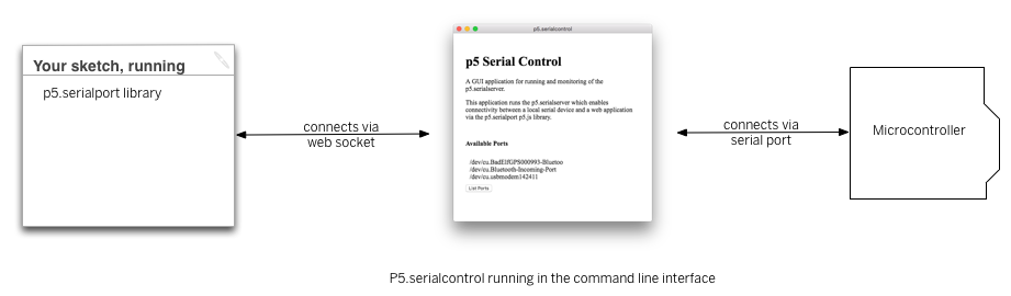
Asynchronous serial communication is not part of the core of p5.js, nor is it part of the core for web browsers. To read serial in a p5.js sketch, or in a web page in general, you need some help. One approach is to open a separate application that connects to the serial port and offers a webSocket connection to the browser. This is the approach that the p5.serialport library and the p5.serialcontrol app take. Another approach is to use the browser API called WebSerial. This is the approach that the p5.webserial library takes.
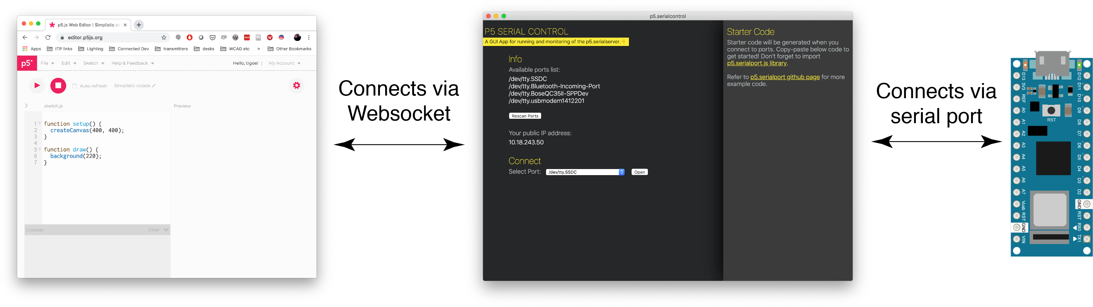
The difference between them is best illustrated by Figures 1 and 2 below. With p5.seriaport, you must open another application on your computer, p5.serialcontrol, to communicate with the serial port. It is this application that handles serial communication, not the p5.js sketch in the browser. This can be more complicated for beginning users.
Figure 1. Diagram of the connection from the serial port to p5.js through p5.serialcontrol
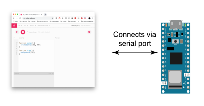
Figure 2. Diagram of the connection from the serial port to p5.js through p5.webserial
p5.serialport/p5.serialcontrol:
p5.webserial:
advantages: * works in all browsers. * Allows your browser to connect to the serial port of a remote computer, if that computer is running a web server program. * Supports opening multiple serial ports at the same time
advantages: * connection is direct to the browser, making it easier for beginners to learn
disadvantages: * requires a third application (p5.serialcontrol), making it more difficult for beginners to learn
disadvantages: * only works in Chrome and Edge browsers * No connection to remote computers * Not sure if it supports a second serial port.
Table 1. Comparing p5.seriaport to p5.webserial
The APIs of p5.serialport and p5.webserial are similar, so it’s pretty straightforward to convert between them.
The code below is a typical p5.serialport setup. You make an instance of the p5.serialport library with the port name, then you make callback functions for the primary tasks:
let serial;          // variable to hold an instance of the serialport library
let portName = '/dev/cu.usbmodem1421';  // fill in your serial port name here

function setup() {
  serial = new p5.SerialPort();       // make a new instance of the serialport library
  serial.on('list', printList);  // set a callback function for the serialport list event
  serial.on('connected', serverConnected); // callback for connecting to the server
  serial.on('open', portOpen);        // callback for the port opening
  serial.on('data', serialEvent);     // callback for when new data arrives
  serial.on('error', serialError);    // callback for errors
  serial.on('close', portClose);      // callback for the port closing

  serial.list();                      // list the serial ports
  serial.open(portName);              // open a serial port
}
The code below is a typical p5.webserial setup. You check t see if WebSerial is available, and then you make an instance of the p5.webserial library, then you look for ports using getPorts():
// variable to hold an instance of the p5.webserial library:
const serial = new p5.WebSerial();
 // port chooser button:
let portButton;
// variable for incoming serial data:
let inData;

function setup() {
   // check to see if serial is available:
   if (!navigator.serial) {
    alert("WebSerial is not supported in this browser. Try Chrome or MS Edge.");
  }
  // check for any ports that are available:
  serial.getPorts();
  // setup function continues below:
Unlike with p5.serialport, you don’t pass in the port name. Instead, the user chooses the port with a pop-up menu:
  // if there's no port chosen, choose one:
  serial.on("noport", makePortButton);
  // open whatever port is available:
  serial.on("portavailable", openPort);
  // setup function continues below:
Then you make callback functions for the primary tasks. These are similar to p5.serialport’s callbacks:
   // handle serial errors:
  serial.on("requesterror", portError);
  // handle any incoming serial data:
  serial.on("data", serialEvent);
  serial.on("close", makePortButton)
  // setup function continues below:
You also add listeners for when the USB serial port enumerates or de-enumerates. This way, if you unplug your serial device or reset it, your program automatically reopens it when it’s available:
  // add serial connect/disconnect listeners from WebSerial API:
  navigator.serial.addEventListener("connect", portConnect);
  navigator.serial.addEventListener("disconnect", portDisconnect);
} // end of setup function
The functions in each API are similar too:
p5.serialport functions (from the library’s guide)
read() returns a single byte of data (first in the buffer)
read() — reads a single byte from the queue (returns a number)
readChar() returns a single char, e,g, ‘A’, ‘a’
readChar() — reads a single byte from the queue as a character (returns a string)
readBytes() returns all of the data available as an array of bytes
readBytes() — reads all data currently available in the queue as a Uint8Array.
readBytesUntil(charToFind) returns all of the data available until charToFind is encountered
readBytesUntil(charToFind) — reads bytes until a character is found (returns a Uint8Array)
readString() returns all of the data available as a string
readStringUntil(charToFind) returns all of the data available as a string until charToFind is encountered
readStringUntil(stringToFind) — reads out a string until a certain substring is found (returns a string)
last() returns the last byte of data from the buffer
lastChar() returns the last byte of data from the buffer as a char
readLine() — read a string until a line ending is found (returns a string)
write() – sends most any JS data type out the port.
write() – sends most any JS data type out the port.
print()– sends string data out the serial port
println() – sends string data out the serial port, along with a newline character.
Table 2. Comparison of p5.serialport and p5.webserial APIs
Both p5.serialport and p5.webserial will do the job of getting bytes from a serial device like an Arduino or other microcontroller to p5.js and vice versa. Which you use depends on what you need. p5.webserial is great if you’re connected directly to the browser’s computer via USB. For most serial applications, this is the way to go. Alternately, p5.serialport offers the advantage that you can run p5.serialcontrol app on your browser’s computer or on another computer on the same network. That way, a browser on your phone or tablet can communicate to the serial device via the computer running p5.serialcontrol.
In this lab you’ll learn how to send data from p5.js to a microcontroller using asynchronous serial communication.
In this lab you’ll learn how to send data from p5.js to a microcontroller using asynchronous serial communication.
Overview
When you use the p5.serialport library for P5.js, it communicates with a webSocket server in the P5.js IDE to give you access to serial devices attached to your computer. This lab shows you how to use P5 to control a microcontroller using asynchronous serial communication.
Figure 2. LEDs. Shown here are four LEDs. The one on the right is an RGB LED. You can tell this because it has four legs, while the others have only two legs.
Figure 3. Resistors. Shown here are 220-ohm resistors. You can tell this because they have two red and one brown band, followed by a gold band.
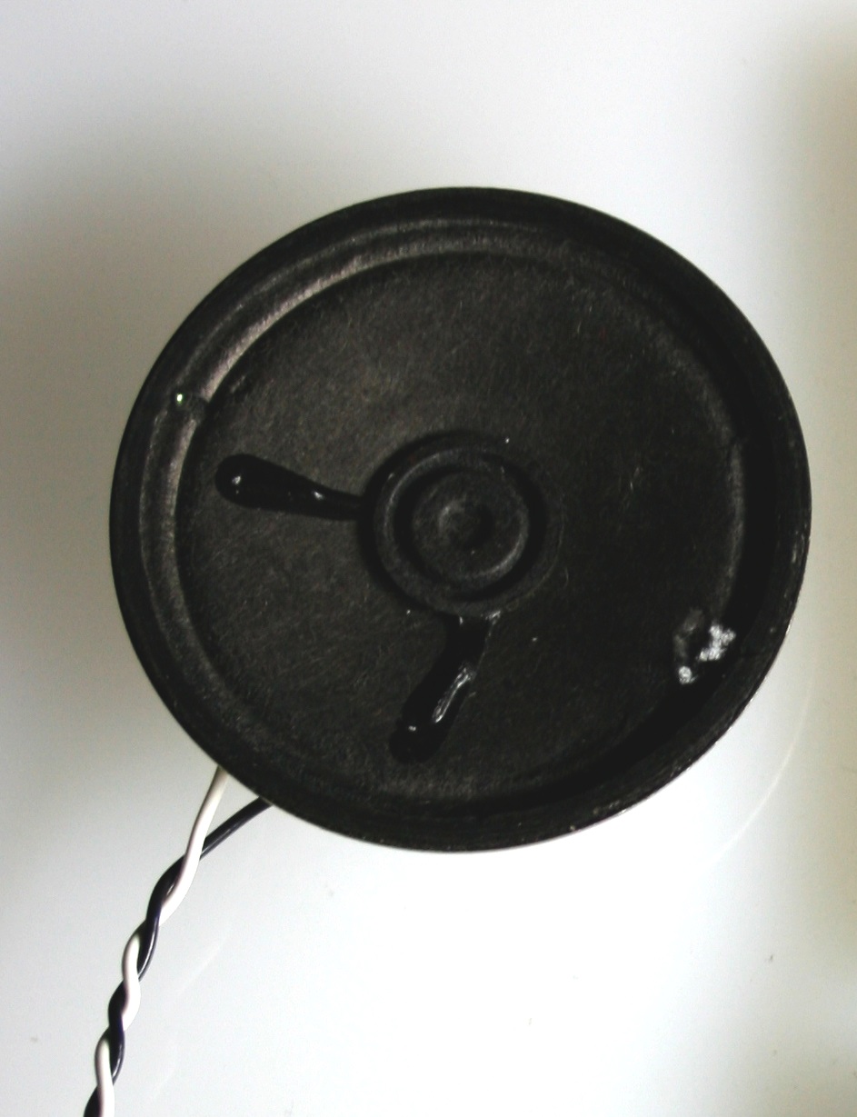
Figure 4. An 8 ohm speaker (optional).This is a good alternate to the LED if you prefer audible output.
Prepare the breadboard
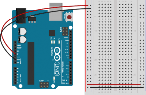
Connect power and ground on the breadboard to power and ground from the microcontroller. On the Arduino UNo, use the 5V and any of the ground connections. On the Nano, use 3.3V and the ground connections:
Figure 5. An Arduino Uno on the left connected to a solderless breadboard, right.
Figure 6. Breadboard view of an Arduino Nano mounted on a breadboard.
The +3.3 volts and ground pins of the Arduino Nano are connected by red and black wires(Figure 6), respectively, to the left side rows of the breadboard. +3.3 volts is connected to the left outer side row (the voltage bus) and ground is connected to the left inner side row (the ground bus). The side rows on the left are connected to the side rows on the right using red and black wires, respectively, creating a voltage bus and a ground bus on both sides of the board.Figure 5. Breadboard view of an Arduino Nano connected to a breadboard. The +3.3 volts and ground pins of the Arduino are connected by red and black wires, respectively, to the left side rows of the breadboard. +3.3 volts is connected to the left outer side row (the voltage bus) and ground is connected to the left inner side row (the ground bus). The side rows on the left are connected to the side rows on the right using red and black wires, respectively, creating a voltage bus and a ground bus on both sides of the board.
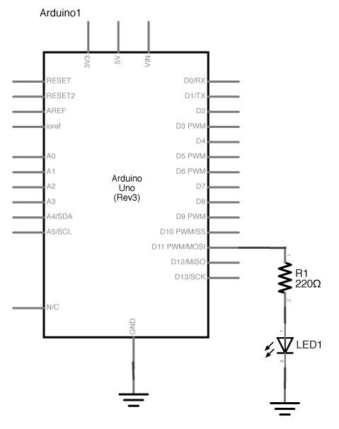
Connect the LED and resistor to digital I/O pin 11 of the module(Figure 7-8). Alternately, you can replace the 220-ohm LED with a speaker (Figure 9-10). You’ll find code below that uses tones instead of LEDs where appropriate. For more on how to do that, see the Tone Output lab:
Figure 7. Schematic view of an Arduino connected to an LED.
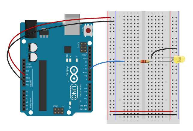
Figure 8. Breadboard view of an Arduino connected to an LED.
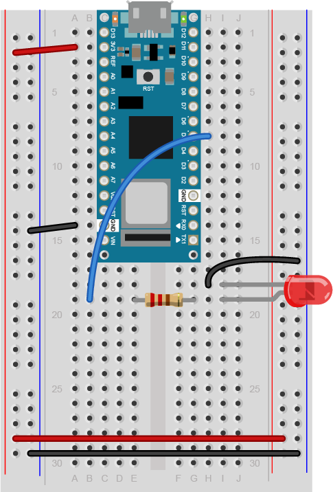
Figure 9. Breadboard view of an LED connected to digital pin 5 of an Arduino Nano.
Figure 9 shows a breadboard view of an LED connected to digital pin 5 of an Arduino Nano. The Nano straddles the center of the breadboard in the first fifteen rows. The Nano’s voltage pin (physical pin 2) connects to the board’s voltage bus, and the Nano’s ground pin (physical pin 14) connects to the board’s ground bus. The LED is in the right center of the board, with its anode in one row and the cathode in the next. A 220-ohm resistor connects the LED’s anode to a wire connecting to digital pin 5. The LED’s cathode is connected to the ground bus.
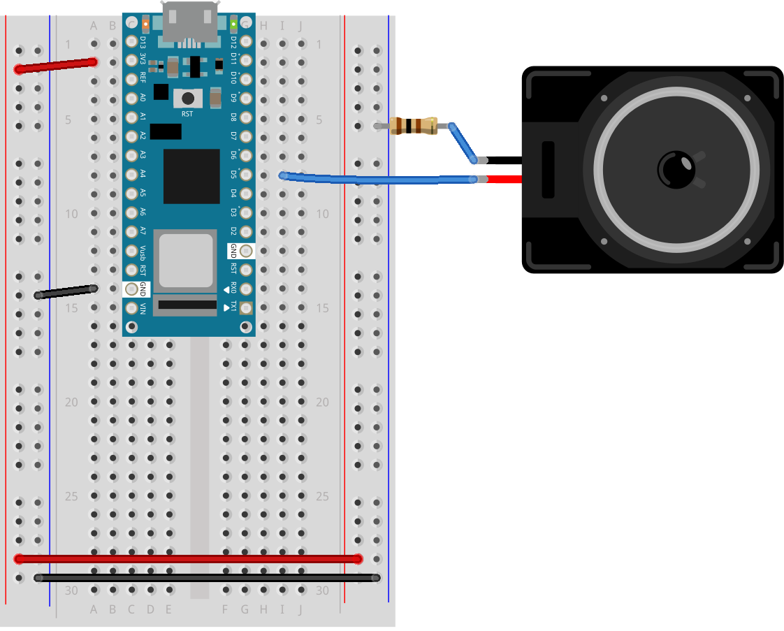
Figure 10. Breadboard view of an Arduino Nano connected to a speaker to digital pin 5.
Figure 10 shows a breadboard view of an Arduino Nano connected to a speaker. The Nano’s ground (physical pin 14) is connected to the ground bus of the breadboard as usual. The red positive wire of the speaker is connected to digital pin 5 of the Arduino. The black ground wire of the speaker is connected to one leg of a 100 ohm resistor. The other leg of the resistor connects to ground.
Program the Microcontroller
Program your Arduino to read the analog input as follows:
void setup() {
  Serial.begin(9600);           // initialize serial communications
}

void loop() {
  if (Serial.available() > 0) { // if there's serial data available
    int inByte = Serial.read();   // read it
    Serial.write(inByte);         // send it back out as raw binary data
    analogWrite(5, inByte);       // use it to set the LED brightness
    // if you're using a speaker instead of an LED, uncomment line below  and comment out the previous line:
    //  tone(5, inByte*10);     // play tone on pin 5
  }
}
The P5.js serialport library
To communicate with your microcontroller serially, you’re going to use the P5.js serialport library and the p5.serialcontrol app. The P5.js serialport library can’t access your serial ports directly when a sketch is running in a browser because the browser doesn’t have direct access to the serial port. But it can communicate with another program on your computer that can exchange data with the serialport. p5.serialcontrol is the app that connects your sketch, running in a browser, with the serial ports on your computer as shown in Figure 11.
Figure 11. Diagram of the connection from the serial port to p5.js through p5.serialcontrol
Once you gain an understanding of serial communication, you can use any program that can connect with your computer’s serial ports to communicate with a microcontroller. Processing, Max/MSP, and OpenFrameworks are three other popular multimedia programming environments that can communicate via the serial ports. You can also do this with Unity, Unreal, or any other programming environment that can access the serial ports.
Install the P5.serialcontrol App
Download the latest version of the P5.serialcontrol application and save it in your Applications folder. When you run it, it will check serial ports on your machine. You don’t need to do anything with the app, just have it open. However, remember this most important fact:
Only one port at a time can access a serial port.
That means that when you want to reprogram your Arduino from the Arduino IDE, you need to quit p5.serialcontrol to do so. Then, reopen p5.serialcontrol when you’re done reprogramming the Arduino. You don’t need to quit the Arduino IDE each time, because it knows to release the serial port when it’s not programming. However, you do need to close the Serial Monitor in the Arduino IDE when you are using p5.serialcontrol.
You’ll need to know the name of your serial port to get started. If you’re not sure how to get this, see the Serial Input to P5.js lab for how to get a list of ports.
The P5.js Sketch
The sketch you’re going to write will control the microcontroller’s LED from P5.js. Dragging the mouse up and down the canvas will dim or brighten the LED, and typing 0 through 9 will set the LED’s brightness in increments from off (0) through almost full brightness (9). There’s an alternate sketch that will make changing tones if you prefer that instead of a changing LED. The sketch will also receive serial input from the microcontroller just as in the Serial Input to P5.js lab, so that you can see that the microcontroller is getting the same values you’re sending.
Program P5.js For Serial Communication
Make a P5.js sketch. If you’re using the p5.js web editor, make a new sketch. Click the Sketch Files tab, and then choose the index.html file. In the head of the document, look for this line:
The setup of your sketch will initialize the P5.serialport library and define your callback functions for serial events. Program the global variables and setup() function as follows:
var serial;          // variable to hold an instance of the serialport library
var portName = '/dev/cu.usbmodem1421'; // fill in your serial port name here
var inData;                            // for incoming serial data
var outByte = 0;                       // for outgoing data

function setup() {
  createCanvas(400, 300);          // make the canvas
  serial = new p5.SerialPort();    // make a new instance of the serialport library
  serial.on('data', serialEvent);  // callback for when new data arrives
  serial.on('error', serialError); // callback for errors
  serial.on('list', printList);       // set a callback function for the serialport list event
  serial.list();                   // list the serial ports

  serial.open(portName);           // open a serial port
}
You’re only using the ‘data’ and ‘error’ and ‘list’ callbacks this time, but you can add the other serial callbacks if you want them. You can also add a serialport select menu as you did in the Serial Input to P5.js lab if you wish.
Program the serialEvent() function and serialError() function similarly to those in the previous lab. They read incoming data (serialEvent()) and report any errors (serialError()), as follows:
function serialEvent() {
  // read a byte from the serial port:
  var inByte = serial.read();
  // store it in a global variable:
  inData = inByte;
}

function serialError(err) {
  println('Something went wrong with the serial port. ' + err);
}
Program the draw() function to display the value of any incoming serial bytes. Here it is:
function draw() {
  // black background, white text:
  background(0);
  fill(255);
  // display the incoming serial data as a string:
  text("incoming value: " + inData, 30, 50);
}
To read the mouse and keyboard, you’ll need to write functions to respond to the ‘mouseDragged’ and ‘keyPressed’ events. ‘MouseDragged’ will happen whenever you click and drag the mouse on the canvas. When that happens, read the mouseY, and map its position on the canvas to a value from 0 to 255. Convert the result to a number using the int() function. Then send it out the serial port using the serial.write() function:
function mouseDragged() {
  // map the mouseY to a range from 0 to 255:
  outByte = int(map(mouseY, 0, height, 0, 255));
  // send it out the serial port:
  serial.write(outByte);
}
The serial.write() function is versatile. If you give it a variable or literal that’s a numeric data type, it will send it as its raw binary value. In the code above, note how you’re converting the output of the map() function to a number using the int() function. If you give it a string, however, it will send out that ASCII string. So be aware of the difference, and make sure you know whether your serial receiving device wants raw binary or ASCII-encoded data.
Program the keyPressed() function similarly to the mouseDragged() function. You want it to read the key strokes, convert them to raw bytes, and send them out the serial port. But you only want to send them if they key hit was 0 through 9. The P5.js variable key returns a numeric value, so you can do math on it and convert it like so:
function keyPressed() {
  if (key >= 0 && key <= 9) { // if the user presses 0 through 9
    outByte = byte(key * 25); // map the key to a range from 0 to 225
  }
  serial.write(outByte); // send it out the serial port
}
That’s all you want your sketch to do, so try running it now. You should see that the initial incoming serial value is undefined, but when you drag the mouse up and down, or type 0 through 9, it will update when the Arduino program returns what it received. The LED will also change with these actions.
Sending ASCII-Encoded Serial Data
If you want to send ASCII-encoded serial data from P5.js, all you have to do is to serial.write() your string. Sending strings is the P5.serialport’s default behavior. On the Arduino side, you can read single characters one byte at a time simply as well. However, if you want to convert multi-byte number strings to numeric values, you’ll need a new function to read ASCII encoded numeric strings called parseInt().
Program the Microcontroller Again
To start off with, load a sketch from the Arduino examples called PhysicalPixel. You can find it in the File Menu -> Examples -> Communication -> PhysicalPixel. Here’s what it looks like. Change the LED pin number to pin 5 as follows:
const int ledPin = 5; // the pin that the LED is attached to
int incomingByte;     // a variable to read incoming serial data into

void setup() {
  Serial.begin(9600);             // initialize serial communication
  pinMode(ledPin, OUTPUT);        // initialize the LED pin as an output
}

void loop() {
  if (Serial.available() > 0) { // see if there's incoming serial data
    incomingByte = Serial.read(); // read it
    if (incomingByte == 'H') {    // if it's a capital H (ASCII 72),
      digitalWrite(ledPin, HIGH); // turn on the LED
      // if you're using a speaker instead of an LED, uncomment line below  and comment out the previous line:
      //  tone(5, 440);           // play middle A on pin 5
    }
    if (incomingByte == 'L') {    // if it's an L (ASCII 76)
      digitalWrite(ledPin, LOW);  // turn off the LED
      // if you're using a speaker instead of an LED, uncomment line below  and comment out the previous line:
      // noTone(5);
    }
  }
}
When you run this, open the serial monitor and type H or L, and the LED will go on or off. Try typing h or l instead. The LED won’t change, because H and h have different ASCII values, as do L and l. But you can see from this that you don’t need to memorize the ASCII chart to check for character values in your code. Put the character you want to read in single quotes, and the Arduino compiler will automatically convert the character to its ASCII value for you. It only works for single characters, though.
Program P5.js To Control the LED
To get P5.js to control this Arduino program serially, you only need to change the keyPressed() function to read H or L instead of 0 through 9. Here’s your new mousePressed() function:
function keyPressed() {
  if (key ==='H' || key ==='L') { // if the user presses H or L
    serial.write(key);              // send it out the serial port
  }
}
Because the key is already a single character, P5.js sends it out as is, and Arduino reads it as a single byte, looking for the ASCII value of H or L. Notice how the values returned to P5.js are 72 and 76, the ASCII values for H and L. For single characters like this, exchanging data is simple.
If you tried to change the LED with the mouse, you didn’t see anything happen unless your output value was 72 or 76. Why is that?
Processing ASCII-Encoded Strings With Arduino
It is also possible to read and interpret ASCII-encoded strings in Arduino. The String.parseInt() function reads an incoming string until it finds a non-numeric character, then converts the numeric string that it read into a long integer. This is a blocking function, meaning that String.parseInt() stops the program and does nothing until it sees a non-numeric character, or until a timeout passes. The timeout is normally one second (or 1000 milliseconds), but you can set it to a lower number of milliseconds using Serial.setTimeout(). Here’s a variation on the original Arduino sketch from above, using Serial.parseInt() this time:
void setup() {
  Serial.begin(9600);    // initialize serial communications
  Serial.setTimeout(10); // set the timeout for parseInt
}

void loop() {
  if (Serial.available() > 0) { // if there's serial data available
    int inByte = Serial.parseInt(); // read it
    if (inByte >= 0) {
      Serial.write(inByte);      // send it back out as raw binary data
      analogWrite(5, inByte);    // use it to set the LED brightness
      // if you're using a speaker instead of an LED, uncomment line below  and comment out the previous line:
      //  tone(5, inByte*10);     // play tone on pin 5
    }
  }
}
Upload this to your microcontroller, then open the Serial Monitor and send in some ASCII numeric strings. You’ll see the character that’s represented by the string’s value. For example, 65 will return A, 34 will return “, and so forth.Notice that this version of the sketch has a conditional statement to check if the incoming byte is 0. This is because of a quirk of the parseInt() function. It returns 0 if the timeout is hit, or if the string is legitimately 0. This means you can’t really parse for a string like this: "0\n".
Program P5.js To Send a String With a Newline Character
Now that your microcontroller is expecting a string, program P5.js to send one. This means changing the mouseDragged() function. You still need to convert it to an integer using the int() function (you could also use round()), but then you need to convert it back to a String and add a delimiter. A quick way to do this is by adding the delimiter in the serial.write() command like so:
serial.write(outByte + '\n');
When the command encounters the two different elements, the number and the string (‘\n’), it will convert the number into a string in in order to concatenate the two. In addition, the newline on the end will is useful on the Arduino side. Since it’s a non-numeric character, the Serial.parseInt() function will see it and parse the string, not waiting for the timeout.
When you’re sending data between two computers using asynchronous serial communication, you have to make sure that what the sender is sending is formatted the same as what the receiver is listening for. See Table 1 to review what are suitable data formats for different types/sizes of data and which functions to use on p5.js and Arduino for serial communication.
Number of Bytes
1 Byte
Multi Bytes
Data to Send
A single number < 255
A single character
A single number > 255, multiple values
Send as:
Binary
Ascii
Ascii
p5.js ->
serial.write(integer)
serial.write(string)
serial.write
(valueToSend + ",")
-> Arduino
Serial.read()
Serial.parseInt()
Table 1. Serial Communication: p5.js to Arduino
Think this out in advance before you code, then consider what functions you’ve got on both computers to convert data from strings to raw binary numbers and back. Test with fixed values at first, so you know you’re getting what you think you should. For example, sending an ASCII-encoded numeric string like this:
1023\n
Will always result in these six bytes:
49 48 50 51 10
Likewise, this text string:
Hello\n
will always be:
72 101 108 108 111 10
By sending a string you know both the ASCII and raw binary representations of, you can test your code easier, because what you’re sending won’t change. Once you know the sending and receiving works, then you can send variable strings.
The more you work with serial data, the more you’ll become familiar with the methods for handling it.
In this tutorial you’ll learn how to send data using asynchronous serial between an Arduino and p5.js in both directions.
Introduction
In the Introduction to Asynchronous Serial Communication lab, you learned about various methods for managing the communications between computers via asynchronous serial communication. These included formatting your data as ASCII-encoded strings or raw serial bytes and managing the flow of data using handshaking. In the P5.js Serial Input Lab, you sent data from one sensor to a personal computer. In this lab, you’ll send data from multiple sensors to a program in P5.js. You’ll use the data from the sensors to create a pointing-and-selecting device (i.e. a mouse).
Figures 1-5 below are the parts you’ll need for this exercise. Click on any image for a larger view.
Figure 1. Microcontroller. Shown here is an Arduino Nano 33 IoT
Figure 2. Jumper wires. You can also use pre-cut solid-core jumper wires.
Figure 3. A solderless breadboard
Figure 4. A pushbutton
Figure 5. two potentiometers. You can use any two analog sensors in place of these if you prefer.
Connect the Sensors
For this exercise, you’re going to need two analog inputs to your microcontroller, and one digital input. It doesn’t matter what they are, so use something that’s easy for you to set up. The photos and schematic in this lab show potentiometers and a pushbutton. You don’t have to use these, though. Any three sensor inputs will do the job. If you’re looking for options, consider:
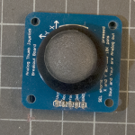
Figure 6. A joystick, which consists of two potentiometers and a pushbutton
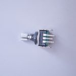
Figure 7. Rotary encoders, which include a built-in pushbutton
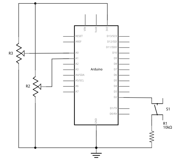
Figure 9. Schematic view of an Arduino attached to two potentiometers and a pushbutton. The potentiometers’ center pins are connected to the Arduino’s A0 and A1 inputs, respectively. Their left pins are connected to the voltage bus, and the right pins are connected to the ground bus, respectively. The pushbutton is connected from the Arduino’s voltage output to pin D2. a 10-kilohm connects the junction of the switch and pin D2 to ground.
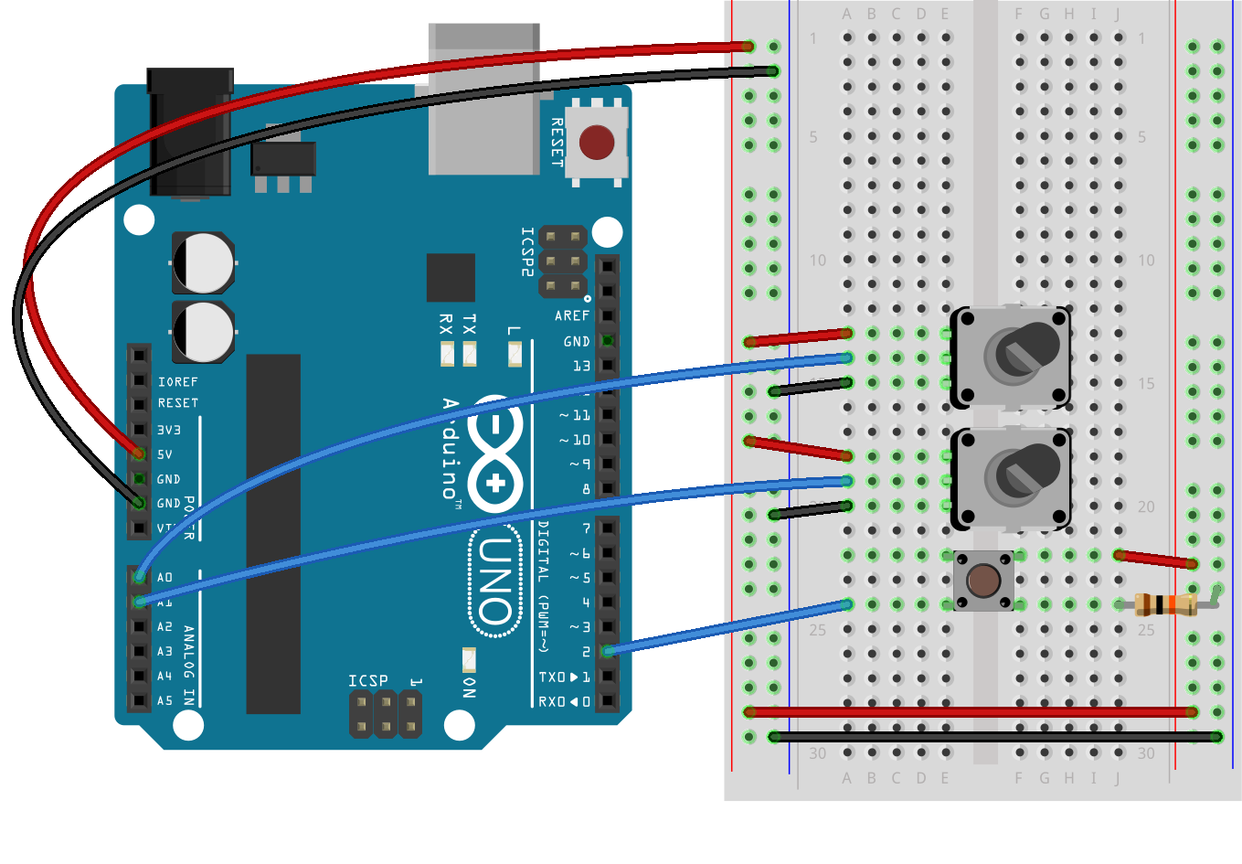
Figure 10. Breadboard view of an Arduino Uno attached to two potentiometers and a pushbutton. The potentiometers’ center pins are connected to the Arduino’s A0 and A1 inputs, respectively. Their left pins are connected to the voltage bus, and the right pins are connected to the ground bus, respectively. The pushbutton is connected from the Arduino’s voltage output to pin D2. a 10-kilohm connects the junction of the switch and pin D2 to ground.
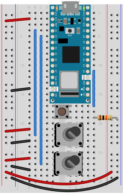
Figure 11. Breadboard view of an Arduino Nano attached to two potentiometers and a pushbutton. The potentiometers’ center pins are connected to the Arduino’s A0 and A1 inputs, respectively. Their left pins are connected to the voltage bus, and the right pins are connected to the ground bus, respectively. The pushbutton is connected from the Arduino’s voltage output to pin D2. a 10-kilohm connects the junction of the switch and pin D2 to ground.
You’re going to program the microcontroller to read the pushbutton and two analog sensors just like you did in the Intro to Serial Communications Lab. When you have to send multiple data items, you need a way to separate them. If you’re sending them as ASCII-encoded strings, it’s simple: you can just put non-numeric punctuation bytes between them (like a comma or a space) and a unique termination punctuation at the end (like a newline and/or carriage return).
This program will send the two analog sensor values and then the pushbutton. All three will be ASCII-encoded numeric strings, separated by commas. The whole line of sensor values will be terminated by carriage return (\r, ASCII 13) and newline (\n, ASCII 10).
const int buttonPin = 2;      // digital input

void setup() {
  // configure the serial connection:
  Serial.begin(9600);
  // configure the digital input:
  pinMode(buttonPin, INPUT);
}

void loop() {
  // read the first analog sensor:
  int sensorValue = analogRead(A0);
  // print the results:
  Serial.print(sensorValue);
  Serial.print(",");

  // read the second analog sensor:
  sensorValue = analogRead(A1);
  // print the results:
  Serial.print(sensorValue);
  Serial.print(",");

  // read the button:
  sensorValue = digitalRead(buttonPin);
  // print the results:
  Serial.println(sensorValue);
}
When you run this and output it to the Serial Monitor, you should see something like this:
Turn the potentiometers (or tweak the analog sensors) and push the button. Now you’ve got a data format: three sensors, comma-separated, terminated by carriage return and newline. This means that you already have an algorithm for how you’re going to program P5.js to read the serial input:
Read the incoming serial data into a string until a carriage return and newline appear
split the string into substrings on the commas
convert the substrings into numbers
assign the numbers to variables to change your programNow that you’ve got a plan, put it into action.
Receive the data in P5.js
Now write a P5.js sketch that reads the data as formatted by the Arduino program above. Download the latest version of the P5.serialcontrol application if you haven’t already and save it in your Applications folder. When you run it, it will check serial ports on your machine. You don’t need to do anything with the app, just have it open.
You’ll need to know the name of your serial port to get started. If you’re not sure how to get this, see the Serial Input to P5.js lab for how to get a list of ports.
The P5.js Sketch
The sketch you’re going to write will control the microcontroller’s LED from P5.js. Dragging the mouse up and down the canvas will dim or brighten the LED, and typing 0 through 9 will set the LED’s brightness in increments from off (0) through almost full brightness (9). There’s an alternate sketch that will make changing tones if you prefer that instead of a changing LED. The sketch will also receive serial input from the microcontroller just as in the Serial Input to P5.js lab, so that you can see that the microcontroller is getting the same values you’re sending.
Make a P5.js sketch. If you’re using the p5.js web editor, make a new sketch. Click the Sketch Files tab, and then choose the index.html file. In the head of the document, look for this line:
The setup of your sketch will initialize the P5.serialport library and define your callback functions for serial events. , as you did in other sketches
Then in the setup(), create a canvas, make an instance of the serialport library, and declare your callback functions.
var serial;          // variable to hold an instance of the serialport library

function setup() {
  createCanvas(800, 600);          // make canvas
  smooth();                        // antialias drawing lines
  serial = new p5.SerialPort();    // make a new instance of the serialport library
  serial.on('list', printList);    // set a callback function for the serialport list event
  serial.on('connected', serverConnected); // callback for connecting to the server
  serial.on('open', portOpen);     // callback for the port opening
  serial.on('data', serialEvent);  // callback for when new data arrives
  serial.on('error', serialError); // callback for errors
  serial.on('close', portClose);   // callback for the port closing

  serial.list();                   // list the serial ports
}
var portSelector; // a select menu for the port list
Then change the printList function like so:
// get the list of ports:
function printList(portList) {
  // make a select menu and position it:
  portSelector = createSelect();
  portSelector.position(10,10);

  // portList is an array of serial port names
  for (var i = 0; i < portList.length; i++) {
    // Display the list the console:
    // console.log(i + " " + portList[i]);
    // add item to the select menu:
    portSelector.option(portList[i]);
  }
  // set a handler for when a port is selected from the menu:
  portSelector.changed(mySelectEvent);
}
When the select menu’s value has changed, you can assume a serial port has been selected, so write a handler to open it like so:
function mySelectEvent() {
  let item = portSelector.value();
   // if there's a port open, close it:
  if (serial.serialport != null) {
    serial.close();
  }
  // open the new port:
  serial.open(item);
}
From now on, when you run this sketch, you’ll need to select the serial port to open the port.
The rest of the serial event handlers are all the same as you saw in the P5.js Serial Input Lab, except for the serialEvent(). Here are all but the serialEvent():
function serverConnected() {
  console.log('connected to server.');
}

function portOpen() {
  console.log('the serial port opened.')
}

function serialError(err) {
  console.log('Something went wrong with the serial port. ' + err);
}

function portClose() {
 console.log('The serial port closed.');
}
Program the serialEvent() function to read the incoming serial data as a string until it encounters a carriage return and newline (‘\r\n’). Then check to see that the resulting string has a length greater than 0 bytes. If it does, use the split() function to split it in to an array of strings. If the resulting array is at least three elements long, you have your three sensor readings. The first reading is the first analog sensor, and can be mapped to the horizontal movement using the locH variable. The second is the second analog sensor and can be mapped to the locV variable. The third is the button. When it’s 0, set the circleColor variable equal to 255 and when it’s 1, set the variable to 0. Here’s how:
function serialEvent() {
  // read a string from the serial port
  // until you get carriage return and newline:
  var inString = serial.readStringUntil('\r\n');

  //check to see that there's actually a string there:
  if (inString.length > 0 ) {
    var sensors = split(inString, ',');            // split the string on the commas
    if (sensors.length > 2) {                      // if there are three elements
      locH = map(sensors[0], 0, 1023, 0, width);   // element 0 is the locH
      locV = map(sensors[1], 0, 1023, 0, height); // element 1 is the locV
      circleColor = 255 - (sensors[2] * 255);      // element 2 is the button
    }
  }
}
Note the mappings of sensor[0] and sensor[1]. You should use the input mappings for your accelerometer instead of 0 and 1023. If your analog values are greater than the width of the sketch or the height, the circle will be offscreen, which is why you have to map your sensor range to the screen size.
Program the draw() function to draw a circle that’s dependent on three global variables, locH, locV, and circleColor. Add these three globals to the top of the program:
var locH = 0;
var locV = 0;        // location of the circle
var circleColor = 255; // color of the circle
Finally, here is the draw function:
function draw() {
  background(0);               // black background
  fill(circleColor);           // fill depends on the button
  ellipse(locH, locV, 50, 50); // draw the circle
}
If you run this, you should see the circle moving onscreen whenever you tilt the accelerometer. When you press the pushbutton, the circle will disappear. Okay, it’s not exactly a mouse, but you are controlling an animation from a device that you built.
Flow Control: Call and Response (Handshaking)
You’ve seen now that by coming up with a serial format (called a protocol), you can write the algorithm for receiving it even before you see any data. You can send multiple pieces of data this way, as long as you format it consistently.
Sometimes you can run into a problem when the sender sends faster than the receiver can read. When this happens, the receiver program slows down as the serial buffer fills up. You can manage this by implementing some form of flow control. The simplest way do to this is using a call-and-response method, where the sending program only sends when it’s told to do so, and the receiving program has to request new data every time it finishes reading what it’s got.
You can add handshaking to the code above fairly simply. Modify the Arduino code as follows. First, add a a new block of code in the setup() This block sends out a message until it gets a byte of data from the remote computer:
void setup() {
  Serial.begin(9600);
  while (Serial.available() <= 0) {
    Serial.println("hello"); // send a starting message
    delay(300);              // wait 1/3 second
  }
}
Now, modify the loop() by adding an if() statement to look for incoming serial data and read it.
void loop() {
  if (Serial.available() > 0) {
    // read the incoming byte:
    int inByte = Serial.read();
    // read the sensor:
    sensorValue = analogRead(A0);
    // print the results:
    Serial.print(sensorValue);
    Serial.print(",");

    // read the sensor:
    sensorValue = analogRead(A1);
    // print the results:
    Serial.print(sensorValue);
    Serial.print(",");

    // read the sensor:
    sensorValue = digitalRead(buttonPin);
    // print the results:
    Serial.println(sensorValue);
  }
}
The rest of the sketch remains the same. When you run this and open the serial monitor, you’ll see:
hello
hello
hello
hello
Type any character in the output box and click Send. You’ll get a string of sensor values at the end of your hellos:
510,497,0
Type another character and click Send. It doesn’t matter what character you send, but the loop will always wait for an incoming byte before sending a new set of sensor values. When you write a program to receive this format, it just has to behave the same way you did:
Open the serial port
Wait for a Hello
Send a byte to request data
Begin loop:
Wait for one set of data
Send a byte to request new data
end loop
Next, modify the P5.js sketch. Most of the changes are in the serialEvent() function. The initial “hello” messages will trigger this function, so when you get a “hello” or any other string, you need to send a byte back so that the Arduino has a byte available to read. Here’s the new serialEvent():
function serialEvent() {
  // read a string from the serial port
  // until you get carriage return and newline:
  var inString = serial.readStringUntil('\r\n');
  //check to see that there's actually a string there:
  if (inString.length > 0) {
    if (inString !== 'hello') { // if you get hello, ignore it
      var sensors = split(inString, ','); // split the string on the commas
      if (sensors.length > 2) { // if there are three elements
        locH = map(sensors[0], 0, 1023, 0, width); // element 0 is the locH
        locV = map(sensors[1], 0, 1023, 0, height); // element 1 is the locV
        circleColor = 255 - (sensors[2] * 255); // element 2 is the button
      }
    }
    serial.write('x'); // send a byte requesting more serial data
  }
}
You also need to add a line to the openPort() function like so:
function portOpen() {
  console.log('the serial port opened.')
  // send a byte to prompt the microcontroller to send:
  serial.write('x');
}
The reason for this is that if your Arduino has already broken out of the loop (let’s say you opened the Serial monitor to check), then it is waiting for a byte from p5.js to send the next block of code. By sending a byte when you know the port has just been opened in p5.js, you force the Arduino to send you new data.
That’s it. Your sketch should still run just as it did before, though the serial communication is managed better now, because Arduino’s only sending when P5.js is ready to receive.
All the examples shown here sent the sensor values as ASCII-encoded strings. As mentioned above, that means you sent three bytes to send a three-digit value. If that same value was less than 255, you could send it in one raw binary byte. So ASCII is definitely less efficient. However, it’s more readable for debugging purposes, and if the receiving program is well-suited to convert strings to numbers, then ASCII is a good way to go. If the receiver’s not so good at converting strings to numbers (for example, it’s more challenging to read a multiple byte string in Arduino than in Processing) then you may want to send your data as binary values.
Advantages of Punctuation or Call-and-Response
The punctuation method for sending multiple serial values may seem simpler, but it has its limitations. You can’t easily use it to send binary values, because you need to have a byte with a unique value for the punctuation. In the example above, you’re using the value 10 (ASCII newline) as punctuation, so if you were sending your sensor values as raw bytes, you’d be in trouble when the sensor’s value is 10. The receiver would interpret the 10 as punctuation, not as a sensor value. In contrast, call-and-response can be used whether you’re sending data as raw binary values or as ASCII-encoded values.
Sometimes the receiver reads serial data slower than the sender sends it. For example, if you have a program that does a lot of graphic work, it may only read serial data every few milliseconds. The serial buffer will get full in that case, you’ll notice a lag in response time. This is when it’s good to switch to a call-and-response method.
Build an Application of Your Own
You just duplicated the basic functionality of a mouse; that is, a device with two analog sensors that affect X and Y, and a digital sensor (mouse button). What applications can you think of that could use a better physical interface for a mouse? A video editor that scrubs forward and back when you tilt a wand? An action game that reacts to how hard you hit a punching bag? An instructional presentation that speeds up if you shift in your chair too much? A music program driven by a custom musical instrument that you design?
Create a prototype in Arduino and P5.js, Node.js, Processing, or whatever programming environment you choose. Come up with a physical interface that makes it clear what actions map to what movements and actions. Figure out which actions can and should be possible at the same time. Present a working software and hardware model of your idea.
n this lab, you’ll generate an analog output value from a potentiometer, then send that value via asynchronous serial communication to P5.js. You’ll use that value in P5.js to draw a graph.
Overview
In this lab, you’ll generate an analog output value from a potentiometer, then send that value via asynchronous serial communication to P5.js. You’ll use that value in P5.js to draw a graph.
Serial communication to a web page in a browser isn’t something you see every day. Web browsers don’t usually have access to a computer’s serial ports. In order to get your browser-based applications to communicate with a microcontroller serially, you need a program that can both serve HTML/JavaScript pages, and communicate with the serial port. When you’re making projects with P5.js, you can achieve this by using the P5.serialport library and the P5.serialcontrol app by Shawn Van Every (updated by Jiwon Shin). When you use the p5.serialport library, it communicates with the p5.serialcontrol app, a WebSocket server that gives you access to serial devices attached to your computer. This lab shows you how to do that.
Figures 1-4 below show the parts you’ll need for this exercise. Click on any image for a larger view.
Figure 1. Microcontroller. Shown here is an Arduino Nano 33 IoT
Figure 2. Jumper wires. You can also use pre-cut solid-core jumper wires.
Figure 3. A solderless breadboard
Figure 4. Potentiometer
Prepare the Breadboard
For this exercise you’re going to attach a potentiometer as an analog input to your microcontroller, and send the sensor’s reading serially to p5.js via the p5.serialcontrol app.
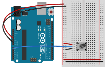
Connect power and ground on the breadboard to the microcontroller. On the Arduino module, use the 5V or 3.3V (depending on your model) and any of the ground connections. Figures 5 and 6 show connections for an Arduino Uno and a Nano, respectively.
Figure 5. An Arduino Uno on the left connected to a solderless breadboard, right.
The Uno’s 5V output hole is connected to the red column of holes on the far left side of the breadboard (Figure 5). The Uno’s ground hole is connected to the blue column on the left of the board. The red and blue columns on the left of the breadboard are connected to the red and blue columns on the right side of the breadboard with red and black wires, respectively. These columns on the side of a breadboard are commonly called the buses. The red line is the voltage bus, and the black or blue line is the ground bus.
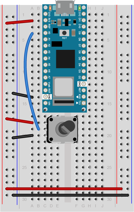
Figure 6. Breadboard view of an Arduino Nano mounted on a breadboard.
Images made with Fritzing, a circuit drawing application
The Nano is mounted at the top of the breadboard (Figure 6), straddling the center divide, with its USB connector facing up. The top pins of the Nano are in row 1 of the breadboard.
The Nano, like all Dual-Inline Package (DIP) modules, has its physical pins numbered in a U shape, from top left to bottom left, to bottom right to top right. The Nano’s 3.3V pin (physical pin 2) is connected to the left side red column of the breadboard. The Nano’s GND pin (physical pin 14) is connected to the left side black column. These columns on the side of a breadboard are commonly called the buses. The red line is the voltage bus, and the black or blue line is the ground bus. The blue columns (ground buses) are connected together at the bottom of the breadboard with a black wire. The red columns (voltage buses) are connected together at the bottom of the breadboard with a red wire.
Add a Potentiometer
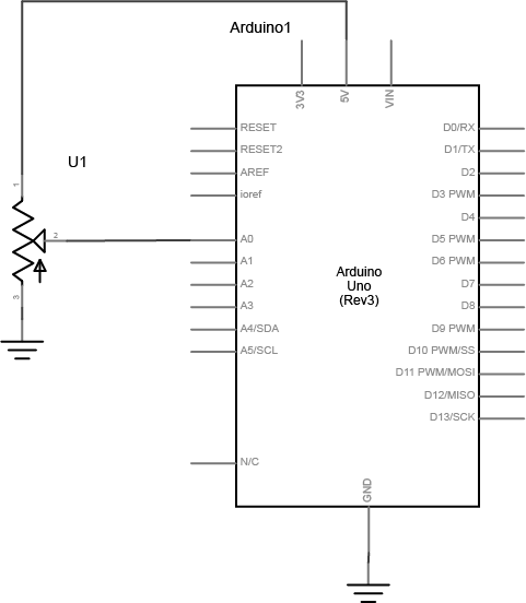
Connect a potentiometer to analog in pin 0 of the module. Figure 7 shows the schematic and figures 8 and 9 show the potentiometer connected to an Arduino and Nano, respectively.
Figure 7. Schematic view of a potentiometer connected to analog in 0 of the Arduino
Figure 8. Breadboard view of a potentiometer connected to analog in 0 of an Arduino. The potentiometer is connected to three rows in the left center section of the breadboard. The two outside pins are connected to voltage and ground. The center pin is connected to the Arduino’s analog in 0.
Figure 9. Breadboard view of a potentiometer connected to analog in 0 of an Arduino Nano. The Nano is connected as usual, straddling the first fifteen rows of the breadboard with the USB connector facing up. Voltage (physical pin 2) is connected to the breadboard’s voltage bus, and ground (physical pin 14) is connected to the breadboard’s ground bus. The potentiometer is connected to three rows in the left center section of the breadboard. The two outside pins are connected to voltage and ground. The center pin is connected to the Nano’s analog in 0.
Program the Microcontroller
Program your Arduino to read the analog input as follows:
void setup() {
  Serial.begin(9600); // initialize serial communications
}

void loop() {
  // read the input pin:
  int potentiometer = analogRead(A0);
  // remap the pot value to fit in 1 byte:
  int mappedPot = map(potentiometer, 0, 1023, 0, 255);
  // print it out the serial port:
  Serial.write(mappedPot);
  // slight delay to stabilize the ADC:
  delay(1);
}
The P5.js Serialport Library
To communicate with your microcontroller serially, you’re going to use the P5.js serialport library and the p5.serialcontrol app. The P5.js serialport library can’t access your serial ports directly when a sketch is running in a browser because the browser doesn’t have direct access to the serial port. But it can communicate with another program on your computer that can exchange data with the serialport. p5.serialcontrol is the app that connects your sketch, running in a browser, with the serial ports on your computer as shown in Figure 10.
Figure 10. Diagram of the connection from the serial port to p5.js through p5.serialcontrol
Once you gain an understanding of serial communication, you can use any program that can connect with your computer’s serial ports to communicate with a microcontroller. Processing, Max/MSP, and OpenFrameworks are three other popular multimedia programming environments that can communicate via the serial ports. You can also do this with Unity, Unreal, or any other programming environment that can access the serial ports.
Install the p5.Serialcontrol App
Download the latest version of the P5.serialcontrol application and save it in your Applications folder. When you run it, it will check serial ports on your machine. You don’t need to do anything with the app, just have it open. However, remember this most important fact:
Only one port at a time can access a serial port.
That means that when you want to reprogram your Arduino from the Arduino IDE, you need to quit p5.serialcontrol to do so. Then, reopen p5.serialcontrol when you’re done reprogramming the Arduino. You don’t need to quit the Arduino IDE each time, because it knows to release the serial port when it’s not programming. However, you do need to close the Serial Monitor in the Arduino IDE when you are using p5.serialcontrol.
Program P5.js to List the Available Serial Ports
Now you’re ready to make a P5.js sketch. If you’re using the p5.js web editor, make a new sketch. Click the Sketch Files tab, and then choose the index.html file. In the head of the document, look for this line:
To start off, your programming environment needs to know what serial ports are available in the operating system. Open the sketch.js file and change it to the following:
let serial; // variable to hold an instance of the serialport library

function setup() {
  serial = new p5.SerialPort(); // make a new instance of the serialport library
  serial.on('list', printList); // set a callback function for the serialport list event

  serial.list(); // list the serial ports
}

// get the list of ports:
function printList(portList) {
  // portList is an array of serial port names
  for (var i = 0; i < portList.length; i++) {
    // Display the list the console:
    console.log(i + portList[i]);
  }
}
When you run this p5.js sketch in a browser, you’ll get a list of the available serial ports in the console. This list will look just like the list of serial ports you see in the Arduino Tools menu. Find the name of your port in the list. Later, you’ll assign that name to a global variable called portName.
Now you’re ready to listen for some incoming serial data.
Serial Events
JavaScript, the language on which p5.js is based, relies heavily on events and callback functions. An event is generated by the operating system when something significant happens, like a serial port opening, or new data arriving in the port. In your sketch, you write a callback function to respond to that event. The serialport library uses events and callback functions as well. It can listen for the following serialport events:
list – the program asks for a list of ports.
connected – when the sketch connects to a webSocket-to-serial server
open – a serial port is opened
close – a serial port is closed
data – new data arrives in a serial port
error – something goes wrong.
You’re already using a callback for the ‘list’ event in the code above. You set a callback for the ‘list’ event, then you called it with serial.list(). Generally, you should set your callbacks before you use them like this.
To use the rest of the serialport library’s events, you need to set callback functions for them as well. Add a new global variable called portName and initialize it with the name of your serial port that you got from the listPorts() function before. Then change your setup() function to include callbacks for open, close, and error like so:
let serial;          // variable to hold an instance of the serialport library
let portName = '/dev/cu.usbmodem1421';  // fill in your serial port name here

function setup() {
  serial = new p5.SerialPort();       // make a new instance of the serialport library
  serial.on('list', printList);  // set a callback function for the serialport list event
  serial.on('connected', serverConnected); // callback for connecting to the server
  serial.on('open', portOpen);        // callback for the port opening
  serial.on('data', serialEvent);     // callback for when new data arrives
  serial.on('error', serialError);    // callback for errors
  serial.on('close', portClose);      // callback for the port closing

  serial.list();                      // list the serial ports
  serial.open(portName);              // open a serial port
}
Notice the final line of the setup(). It’s going to generate an ‘open’ event, which will be handled by a function called portOpen().
Wait a Minute! Don’t I have to Set the Data Rate When I Open the Port?
In asynchronous serial communications, both computers have to set the same data rate in order to communicate. In Arduino, you set the data rate with Serial.begin(9600); In p5.js, 9600 bits per second is the default, so you don’t have to set the rate if you want 9600bps. But if you want to set the rate to another value, do it like this:
let options = { baudrate: 9600}; // change the data rate to whatever you wish
serial.open(portName, options);
Now add new functions to respond to the callbacks you just declared. These come after your setup() function:
function serverConnected() {
  console.log('connected to server.');
}

function portOpen() {
  console.log('the serial port opened.')
}

function serialEvent() {

}

function serialError(err) {
  console.log('Something went wrong with the serial port. ' + err);
}

function portClose() {
  console.log('The serial port closed.');
}
The function that matters the most, though, is serialEvent(), the one that responds to new data. Each time a new byte arrives in the serial port, this function is called. Now it’s time to make serialEvent() do some work. Add a new global variable at the top of your sketch called inData like so:
let serial;          // variable to hold an instance of the serialport library
let portName = '/dev/cu.usbmodem1421';  // fill in your serial port name here
let inData;                             // for incoming serial data
Then modify the serialEvent() function like so:
function serialEvent() {
  inData = Number(serial.read());
}
Next, make the draw() function to print the sensor value to the screen. Start by adding a createCanvas() call to the top of your setup() like so:
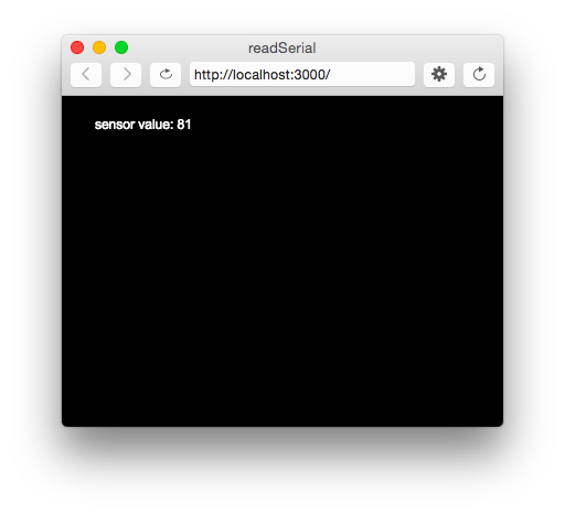
Figure 13. A screenshot of the sketch running in a browser. The sketch prints the sensor value in text on the screen.
When you run your sketch now, you should get something like the sketch shown in Figure 13.
The sensor value onscreen should change as you turn your potentiometer. Congratulations! You’ve got P5.js talking to your microcontroller.
What’s Happening Here
Every time your microcontroller sends a byte serially using Serial.write(), the computer receives it and generates a ‘data’ event. Then your serialEvent() function is called. It reads the byte as a number, and stores it in the global variable inData. The draw() method just uses the latest value of inData in the text string it displays on the screen.
You may be wondering why you’re mapping the sensor value or dividing it by 4 in the Arduino sketch above. That’s because in order to send the sensor value as a single byte, it must be between 0 and 255, or no more than 28 bits.
P5.js Console.log() and Arduino delay(): a Tricky Combination
In testing this, you may have put a console.log() statement in the serialEvent() function in your P5.js sketch. When you did, you would have noticed that it causes a lag in the sketch, and the console.log() statements continue even after you stop the sketch. This is because the operating system keeps the incoming serial data in a buffer, and P5.js isn’t reading and printing it as fast as Arduino is sending it.
You might think, “Okay, then I’ll just put a delay() in my Arduino sketch to slow it down.” That’s a bad idea. When you put in a delay, it means you’re only reading your sensor when that delay is not running. You can miss critical sensor events while that delay is in progress. Even a relatively small delay, for example 30ms, can make it difficult to reliably read state changes in a switch or peaks in an analog sensor. Don’t use delays if you can avoid it. For more on how to handle the flow of serial data from Arduino to P5.js and back, see the Duplex Serial Flow in P5.js lab.
Adding A Serial Port Select Menu
If you don’t want to have to remember the serial port name every time you run the sketch, you can add a drop-down menu to select the port. Add a global variable at the top of your sketch called portSelector like so:
// HTML Select option object:
let portSelector;
Then replace the printList() function with the following:
// make a serial port selector object:
function printList(portList) {
// create a select object:
portSelector = createSelect();
portSelector.position(10, 10);
// portList is an array of serial port names
for (var i = 0; i < portList.length; i++) {
// add this port name to the select object:
portSelector.option(portList[i]);
}
// set an event listener for when the port is changed:
portSelector.changed(mySelectEvent);
}
Then add an extra function that will get called when the port list is changed. This function will get the name of the port you select, close any port that’s open, and open the port you asked for:
function mySelectEvent() {
let item = portSelector.value();
// if there's a port open, close it:
if (serial.serialport != null) {
serial.close();
}
// open the new port:
serial.open(item);
}
If you choose this approach, you can delete the global portName variable at the top of your sketch, and the line in your setup() that says:
serial.open(portName); // open a serial port
Instead of opening the serial port once at the beginning of your code, you’re now opening and closing the port every time you select from this menu.
Draw a Graph With the Sensor Values
It would be useful to see a graph of the sensor values over time. You can do that by modifying the draw() method to draw the graph. To do this, add a new global variable at the top of your sketch called xPos. You’ll use this to keep track of the x position of the latest graph line:
let xPos = 0; // x position of the graph
Because of the way the graphing function below works, you can’t reset the background every time through the draw() loop. So take the background() command and put it in the setup() function instead of the draw(), as shown below. That way it runs once, then not again. As long as you’re at it, switch from black & white to a nice blue color:
function setup() {
createCanvas(400, 300);
background(0x08, 0x16, 0x40);
Now make a new function called graphData(). It’ll take a number value as a parameter, and it will draw a line on the screen that’s mapped to the number value. Then it will increment xPos so that the next line is drawn further along. It will also check if the xPos is at the right edge of the screen, and reset the screen by calling background() again if it is:
function graphData(newData) {
  // map the range of the input to the window height:
  var yPos = map(newData, 0, 255, 0, height);
  // draw the line in a pretty color:
  stroke(0xA8, 0xD9, 0xA7);
  line(xPos, height, xPos, height - yPos);
  // at the edge of the screen, go back to the beginning:
  if (xPos >= width) {
    xPos = 0;
    // clear the screen by resetting the background:
    background(0x08, 0x16, 0x40);
  } else {
    // increment the horizontal position for the next reading:
    xPos++;
  }
}
Finally, take everything out of the draw() function and just call graphData() from there:
function draw() {
  graphData(inData);
}
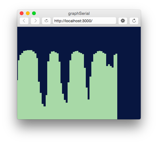
When you run the sketch now, you should get a graph, as shown in Figure 14.
Figure 14. Screenshot of the serial graph p5.js sketch. The sensor’s values are graphed on the screen
If you’d like to see a fancier graphing sketch, check out this sketch, which adds chart.js to make a better graph. Chart.js is a great tool for graphing data in JavaScript, and it integrates well with p5.js.
Reading Serial Data as a String
This works well if you want to read your sensor values as a single byte, but what if you want a larger range of numbers? What if you want the full 0 to 1023 that analogRead() can output instead of just 0 to 255? To do this, you need to send the data as an ASCII-encoded numeric string from the microcontroller, and you need to read and interpret the incoming data in P5 as an ASCII-encoded numeric string as well.
Change your Arduino program to the following:
void setup() {
 Serial.begin(9600); // initialize serial communications
}

void loop() {
 int potentiometer = analogRead(A0);                  // read the input pin
 int mappedPot = map(potentiometer, 0, 1023, 0, 255); // remap the pot value to fit in 1 byte
 Serial.println(mappedPot);                           // print it out the serial port
 delay(1);                                            // slight delay to stabilize the ADC
}
Now it will print the potentiometer’s value as an ASCII-encoded numeric string, and it will add a carriage return byte and a newline byte at the end, because that’s what println() does.
Once you’ve uploaded this to your Arduino, run your P5 sketch again. Try adding println(inData);at the end of your serialEvent() function. When your P5 sketch reads the data from this Arduino program, you get very low values, and every so often you see the value 10 followed by the value 13. What’s going on?
When a computer ASCII-encodes a number, it converts that number to a string of bytes, each of which is the ASCII value for a numeral in the number. For example, the number 865 gets converted to three bytes, as shown in Figure 15.
Figure 15. The decimal number 865 when sent serially as ASCII is three bytes long. The first byte representing digit, 8, has the ASCII value 58. The second byte representing the digit 6 has the ASCII value 54. The third byte representing the digit 5 has the ASCII value 53.
If there’s a carriage return byte and a newline byte after this, the string is five bytes, and the last two bytes’ values are 13 (carriage return, or \r in most programming languages) and 10 (newline or \n in most programming languages), respectively.
Your P5.js sketch is reading every byte’s value and graphing it. That’s why you get a graph of very low values, with a bunch of them being 13 and 10. The Arduino is ASCII-encoding the potentiometer values, but the P5 sketch is interpreting the bytes as if they’re not encoded that way.
Now change the serialEvent() function like so:
function serialEvent() {
  // read a byte from the serial port, convert it to a number:
  inData = serial.readLine();
}
Run it again. What’s changed? Now you’re getting a graph kind of like you were before. The serial.readLine();command reads the incoming serial data as a string, and when that string happens to be all-numeric, it converts it to a number. So you’re getting the ASCII-encoded string as a number again. But now there are gaps. Why?
Remember, the ‘data’ event occurs every time a new byte comes in the serial port. Now that you’re sending an ASCII-encoded string, every potentiometer reading is several bytes long. So you only get a complete string every three to six bytes (three for “0\r\n” and six for “1023\r\n”). Sometimes, when the serialEvent() function calls serial.readLine(); it gets nothing. That’s when draw() draws the gaps. You need to change your function to check that the resulting string is actually a valid number before you put the string into inData. First, create a local variable to get the string, then check to see if the string’s length is greater than zero. If it is, then put it into inData so that the other functions in the sketch can use the new data. Here’s how you do that:
function serialEvent() {
  // read a string from the serial port:
  var inString = serial.readLine();
  // check to see that there's actually a string there:
  if (inString.length > 0 ) {
  // convert it to a number:
  inData = Number(inString);
  }
}
Now you’re able to send in a number of any value to P5.js. You don’t have to limit your input to a 0-255 value range. See if you can modify the Arduino sketch and the P5.js sketch to exchange a potentiometer value that spans the whole range from 0 to 1023.
note: readLine() is the same as readStringUntil(‘\r\n’);
Optional: Accessing a Serial Sketch From Another Computer
You know that p5.js can run in any browser, but what happens to a sketch using p5.serialport.js when it’s running on someone else’s computer, or on your phone or tablet? What serial port does it connect to? That depends on what you do when you initialize it.
When you call new p5.SerialPort() with no parameter between the parentheses, the library attempts to connect to p5.serialcontrol app on the computer that’s running the sketch. If you’re running the sketch on your laptop’s browser, then the library connects to the your laptop’s ports through p5.serialcontrol. But imagine you run the sketch on your phone, but you want the sketch to connect to an Arduino connected to a serial port on your laptop. To do this, the your laptop has to be the web host for your sketch, as well as the computer running p5.serialcontrol. In addition, your laptop and the device running the sketch have to be on the same local network.
note: this will not work if your sketch is in the p5.js web editor. You’ll need to download the sketch and edit it on your laptop to make it work.
Launch the p5.serialcontrol app. It will display the IP address of the computer on which it’s running. Copy it, and modify the new p5.SerialPort() line at the beginning of your setup() function, adding the IP address like so:
serial = new p5.SerialPort('10.17.34.128'); // fill in your own IP address in place of the one shown here
Save the sketch, then open a command line interface on your computer (the Terminal app in MacOS, for example). Change directories to the directory where your sketch lives (for example, cd ~/Documents/p5_sketches/mySerialSketch) and run a simple web server like so:
$ python -m SimpleHTTPServer 8080
Now open a browser, either on your computer or your phone or tablet, and enter the following address:
http://your.ip.address:8080
To close this server, type control-C. You can modify the sketch as much as you want, and reload it in the browser without having to re-start the server.
The sketch should run, and operate just as you saw earlier. This approach is handy if you want to use a tablet or phone as a multimedia device to control sounds or videos, controlled by physical sensors on a microcontroller.
Note: the IP address of your computer will change as you move from one network to another (for example, from school to home). If you want to get the IP address dynamically, you can use this: window.location.hostname. This will always return the address of the host computer that served the webpage. So, for example, changing the line above to read as follows will automatically adjust the hostname each time.
// use the hostname of the computer that served this page:
serial = new p5.SerialPort(window.location.hostname);
In this lab, you saw how to connect an Arduino microcontroller to a P5.js sketch using a webSocket-to-serial server, P5.serialserver, and the P5.serialport library. You sent data from Arduino to the sketch as a raw binary value — that is, a single byte ranging from 0 to 255 — and you sent it as an ASCII-encoded numeric string with a carriage return and newline at the end. See Table 1 below to review what are suitable data formats for different types/sizes of data and which functions to use on p5.js and Arduino for serial communication.
Data to Send
A single value
within 0-255
(< 2^8 = 1 byte)
Larger numbers & characters in Ascii Table,
Multiple values
Send as:
Binary
Ascii
Arduino ->
Serial.write()
Serial.println()
-> p5.js
serial.read()
serial.readLine()
=readStringUntil('\r\n')
Table 1. Serial Communication: Arduino to p5.js
Notes about sending Ascii data:
Using Serial.println() on Arduino and serial.readLine() on p5.js is one of many different ways of sending Ascii data from Arduino to p5.js with serial communication.
If you want to use the value as a numeric value not a string, convert the value into number by using Number().
Understanding the difference between ASCII-encoded strings and raw binary data is central to all serial communications. For more examples of this in action, see the Serial Output from P5.js lab.