Introduction
In this lab, you’ll connect a digital input circuit and a digital output circuit to a microcontroller. Though this is written for the Arduino microcontroller module, the principles apply to any microcontroller.
Digital input and output are the most fundamental physical connections for any microcontroller. The pins to which you connect the circuits shown here are called General Purpose Input-Output, or GPIO, pins. Even if a given project doesn’t use digital in and out, you’ll often use LEDs and pushbuttons or switches during the development for testing whether everything’s working.
What You’ll Need to Know
To get the most out of this lab, you should be familiar with the following concepts and you should install the Arduino IDE on your computer. You can check how to do so in the links below:
- What is a microcontroller
- Beginning programming terms
- The basics of electricity
- What is a solderless breadboard and how to use one
- Getting Started with Arduino Guide
- Notes on Microcontroller Digital In and Out
Things You’ll Need
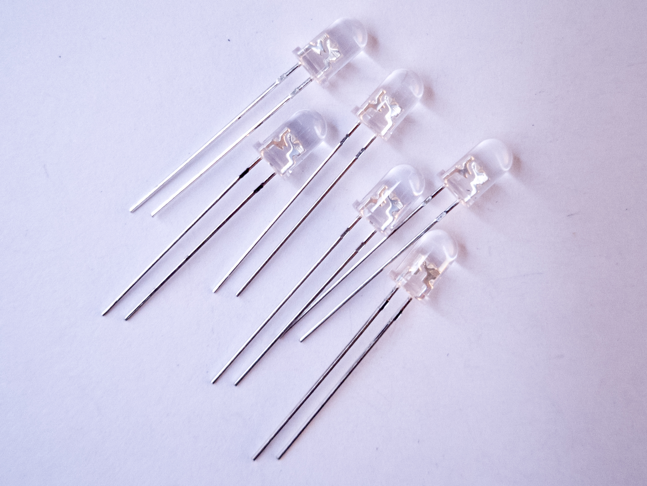
Figures 1-8 show the parts you’ll need for this exercise. Click on any image for a larger view.


Related video
The video Video: Digital Output covers the material in this lab.
Prepare the breadboard
If you’re using a brand new breadboard, you might want to check out these videos before you get started, to prep your board and care for your microcontroller.
Connect power and ground on the breadboard to power and ground from the microcontroller. On the Arduino Uno, use the 5V or 3.3V (depending on your model) and any of the ground connections. Figures 9 and 10 show how to do this for an Arduino Uno and for an Arduino Nano 33 IoT.

As shown in Figure 9, the Uno’s 5V output hole is connected to the red column of holes on the far left side of the breadboard. The Uno’s ground hole is connected to the blue column on the left of the board. The red and blue columns on the left of the breadboard are connected to the red and blue columns on the right side of the breadboard with red and black wires, respectively. These columns on the side of a breadboard are commonly called the buses. The red line is the voltage bus, and the black or blue line is the ground bus.

As shown in Figure 10, the Nano is mounted at the top of the breadboard, straddling the center divide, with its USB connector facing up. The top pins of the Nano are in row 1 of the breadboard.
The Nano, like all Dual-Inline Package (DIP) modules, has its physical pins numbered in a U shape, from top left to bottom left, to bottom right to top right. The Nano’s 3.3V pin (physical pin 2) is connected to the left side red column of the breadboard. The Nano’s GND pin (physical pin 14) is connected to the left side black column. These columns on the side of a breadboard are commonly called the buses. The red line is the voltage bus, and the black or blue line is the ground bus. The blue columns (ground buses) are connected together at the bottom of the breadboard with a black wire. The red columns (voltage buses) are connected together at the bottom of the breadboard with a red wire.
Images made with Fritzing
Related video: Overview of the Arduino microcontroller
Related video: Connect Power and Ground using wires
Add a Digital Input (a Pushbutton)
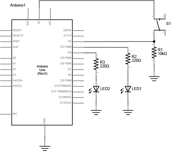
Connect a pushbutton to digital input 2 on the Arduino. Figures 11 and 12 show the schematic and breadboard views of this for an Arduino Uno, and Figure 13 shows the breadboard view for an Arduino 33 IoT. The pushbutton shown below is a store-bought momentary pushbutton, but you can use any pushbutton. Try making your own with a couple of pieces of metal as shown in the Switches lab.
Related video: Connect a pushbutton to a digital pin
What Are The Input and Output Pins?
If you’re not sure what pins are the inputs and outputs of your board, check the Microcontroller Pin Functions page for more information. The reference page on the standard breadboard layouts for the Uno, Nano series, and MKR series might be useful as well.
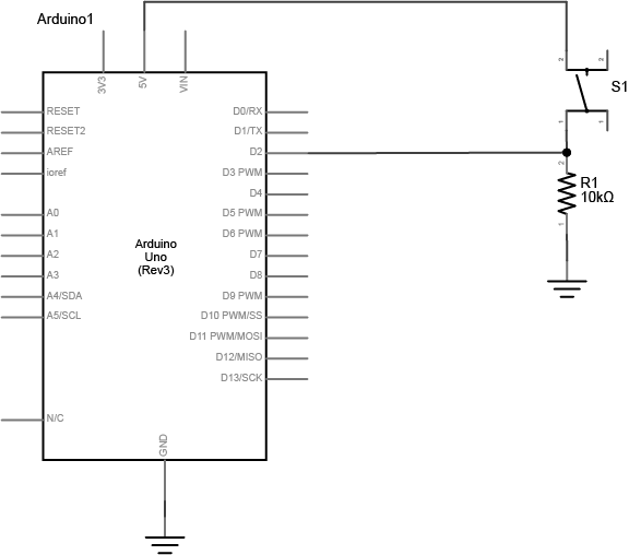
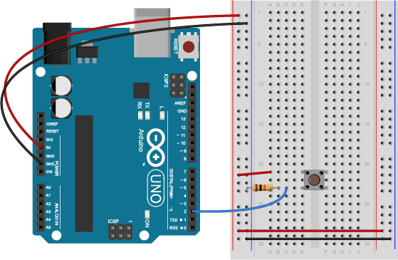
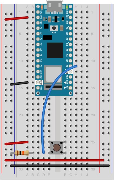
Figure 13 shows the breadboard view of an Arduino Nano connected to a pushbutton. The +3.3 volts and ground pins of the Arduino are connected by red and black wires, respectively, to the left side rows of the breadboard. +3.3 volts is connected to the left outer side row (the voltage bus) and ground is connected to the left inner side row (the ground bus). The side rows on the left are connected to the side rows on the right using red and black wires, respectively, creating a voltage bus and a ground bus on both sides of the board. The pushbutton is mounted across the middle divide of the solderless breadboard. A 10-kilohm resistor connects from the same row as pushbutton’s bottom left pin to the ground bus on the breadboard. There is a wire connecting to digital pin 2 from the same row that connects the resistor and the pushbutton. The top left pin of the pushbutton is connected to +3.3V.
Note on The Pulldown Resistor
What happens if you don’t include the resistor connecting the pushbutton to ground? The resistor connecting the pushbutton is a pulldown resistor. It provides the digital input pin with a connection to ground. Without it, the input will behave unreliably.
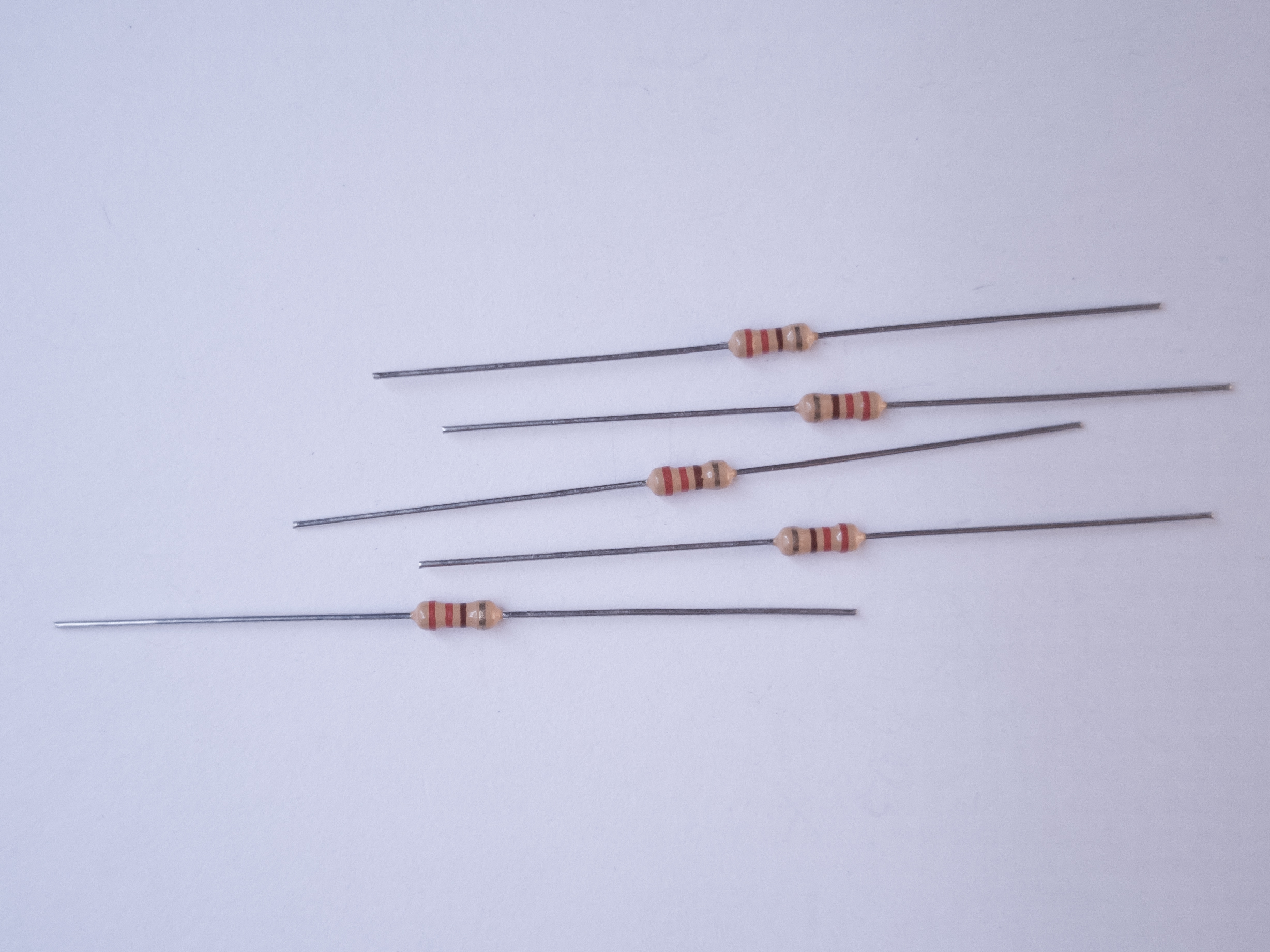
If you don’t have a 10-kilohm resistor for the pushbutton, you can use any reasonably high value. 4.7K, 22K, and even 1 Megohm resistors have all been tested with this circuit and they work fine. See the digital input and output notes for more about the digital input circuit.
If you’re not sure about the resistor color codes, use a multimeter to measure the resistance of your resistors in ohms, and check this resistor color code calculator.
Add Digital Outputs (LEDs)
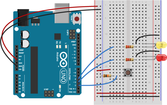
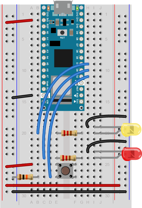
Connect a 220-ohm resistor and an LED in series to digital pin 3 and another to digital pin 4 of the Arduino. Figures 14, 15, and 16 below show the schematic view as well as the breadboard view for both the Uno and the Nano. If you prefer an audible tone over a blinking LED, you can replace the LEDs with speakers or buzzers. The 220-ohm resistor will work with LED, speaker, or buzzer.
Note on LED Resistor Values
For the resistor on the LED, the higher the resistor value, the dimmer your LED will be. So 220-ohm resistors give you a nice bright LED, 1-kilohm will make it dimmer, and 10K or higher will likely make it too dim to see. Similarly, higher resistor values attenuate the sound on a speaker, so a resistor value above 220-ohm will make the sound from your speaker or buzzer quieter.
Related video: Resistors for an LED
Program the Arduino
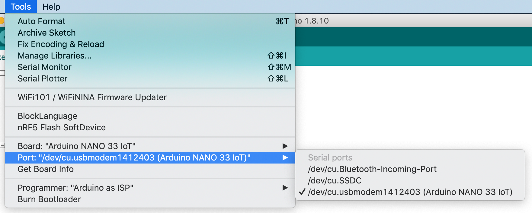
Make sure you’re using the Arduino IDE version 1.8.19 or later. If you’ve never used the type of Arduino module that you’re using here (for example, a Nano 33 IoT), you may need to install the board definitions. Go to the Tools Menu –> Board submenu –> Board Manager. A new window will pop up. Search for your board’s name (for example, Nano 33 IoT), and the Boards manager will filter for the correct board. Click install and it will install the board definition.
Connect the microcontroller to your computer via USB. When you plug the Arduino into your computer, you’ll find a new serial port in the Tools–>Port menu (for details on installing the software, and USB-to-serial drivers for older Arduino models on Windows, see the Arduino Getting Started Guide). In the MacOS, the name look like this: /dev/tty.usbmodem-XXXX (Board Type) where XXXX are part of the board’s unique serial number and Board Type is the board type (for example, Arduino Uno, Nano 33 IoT, MKRZero, etc.) In Windows it will be called COM and a number. Figure 17 shows the tools men and its Port submenu.
Now it’s time to write a program that reads the digital input on pin 2. When the pushbutton is pressed, turn the yellow LED on and the red one off. When the pushbutton is released, turn the red LED on and the yellow LED off.
In your setup() method, you need to set the three pins you’re using as inputs or outputs, appropriately.
 void setup() {
   pinMode(2, INPUT);    // set the pushbutton pin to be an input
   pinMode(3, OUTPUT);   // set the yellow LED pin to be an output
   pinMode(4, OUTPUT);   // set the red LED pin to be an output
 }
In the main loop, first you need an if-then-else statement to read the pushbutton. If you’re replacing the LED with a buzzer, the code below will work as is. If you’re using a speaker, there’s an alternative main loop just below the first one:
void loop() {
   // read the pushbutton input:
   if (digitalRead(2) == HIGH) {
     // if the pushbutton is closed:
     digitalWrite(3, HIGH);    // turn on the yellow LED
     digitalWrite(4, LOW);     // turn off the red LED
   }
   else {
     // if the switch is open:
     digitalWrite(3, LOW);     // turn off the yellow LED
     digitalWrite(4, HIGH);    // turn on the red LED
   }
 }
Here’s an alternate loop function for an audible output on two speakers. If you want to use only one speaker, try alternating the tone frequency from 440Hz (middle A) to 392Hz (middle G):
void loop() {
   // read the pushbutton input:
   if (digitalRead(2) == HIGH) {
     // if the pushbutton is closed:
     tone(3, 440);    // turn on the first speaker to 440 Hz
     noTone(4);     // turn off the second speaker
   }
   else {
     // if the switch is open:
     noTone(3);     // turn off the first speaker
     tone(4, 440);    // turn on the second speaker to 440 Hz
   }
 }
Once you’re done with that, you’re ready to compile your sketch and upload it. Click the Verify button to compile your code. Then click the Upload button to upload the program to the module. After a few seconds, the following message will appear in the message pane to tell you the program was uploaded successfully. Related video: Upload the code to the Arduino
Binary sketch size: 5522 bytes (of a 7168 byte maximum)
Press the pushbutton and watch the LEDs change until you get bored. That’s all there is to basic digital input and output!
The Uno vs Newer Boards
If you’ve used an Uno r3 board before (the “classic Uno”), and are migrating to the Nano or a newer board, you may notice that the serial connection behaves differently. When you reset the MKR, Nano, Uno R4, or Leonardo boards, or upload code to them, the serial port seems to disappear and re-appear. Here’s why:
There is a difference between the Uno R3 and most of the newer boards like the MKR boards, the Nano 33 IoT and BLE, the Leonardo and the Uno R4: the Uno R3 has a USB-to-serial chip on the board which is separate from the microcontroller that you’re programming. The Uno R3’s processor, an ATMega328, cannot communicate natively via USB, so it needs the separate processor. That USB-to-serial chip is not reset when you upload a new sketch, so the port appears to be there all the time, even when your Uno R3 is being reset.
The newer boards can communicate natively using USB. They don’t need a separate USB-to-serial chip. Because of this, they can be programmed to operate as a mouse, as a keyboard, or as a USB MIDI device. Since they are USB-native, their USB connection gets reset when you upload new code or reset the processor. That’s normal behavior for them; it’s as if you turned off the device, then turned it back on. Once it’s reset, it will let your computer’s operating system know that it’s ready for action, and your serial port will reappear. This takes a few seconds. It means you can’t reset the board, and then open the serial port in the next second. You have to wait those few seconds until the Arduino board has made itself visible to the computer’s operating system again.
If you have problems with the UBS-native boards’ serial connection, tap the reset button once, then wait a few seconds, then see if the port shows up again once the board has reset itself. You can also double-tap the reset on the MKR and Nano boards to cause the processor to reset and go into a sleep mode. In this mode, the USB connection will reset itself, but your sketch won’t start running. The built-in LED will glow softly. Then upload a blank sketch. From there, you can start as if your board was brand new.
Applications
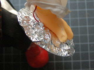
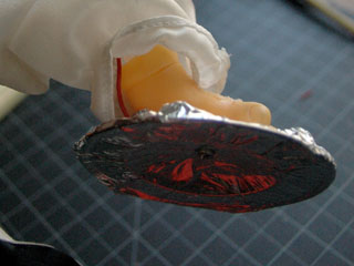
Many projects can be made with just digital input and output. For example, a combination lock is just a series of pushbuttons that have been pushed in a particular sequence. Consider the cymbal-playing monkey in Figures 18-20:
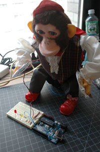
The monkey’s cymbals can be turned into a switch by lining them with tin foil and screwing wires to them:
Those wires can be run to a breadboard and used as a switch. Then the microcontroller could be programmed to listen for pattern of cymbal crashes, and if it sees that pattern, to open a lock by turning on a digital output.
Consider the project ideas from Project 1 for more applications you can do with simple input and output.