This lab covers the process of taking MIDI messages sent from the Arduino and creating sound with them via a Digital Audio Workstation (DAW) such as Ableton LIVE, Logic or Garageband.
Introduction
This lab covers the process of taking MIDI messages sent from the Arduino and creating sound with them via a Digital Audio Workstation (DAW) such as Ableton LIVE, Logic or Garageband.
What You’ll Need to Know
To get the most out of this lab, you should be familiar with the following concepts. You can check how to do so in the links below:
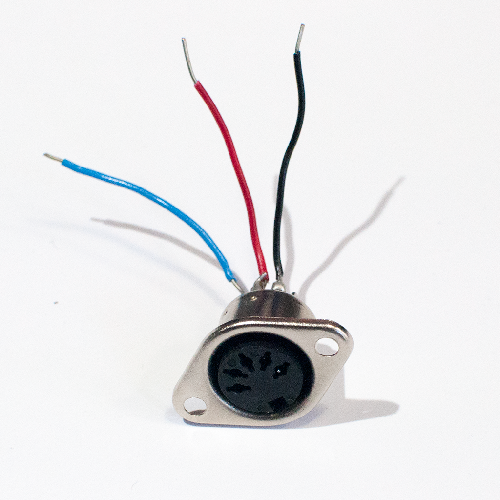
Figure 5. A 5-pin MIDI socket (for the Uno version only)
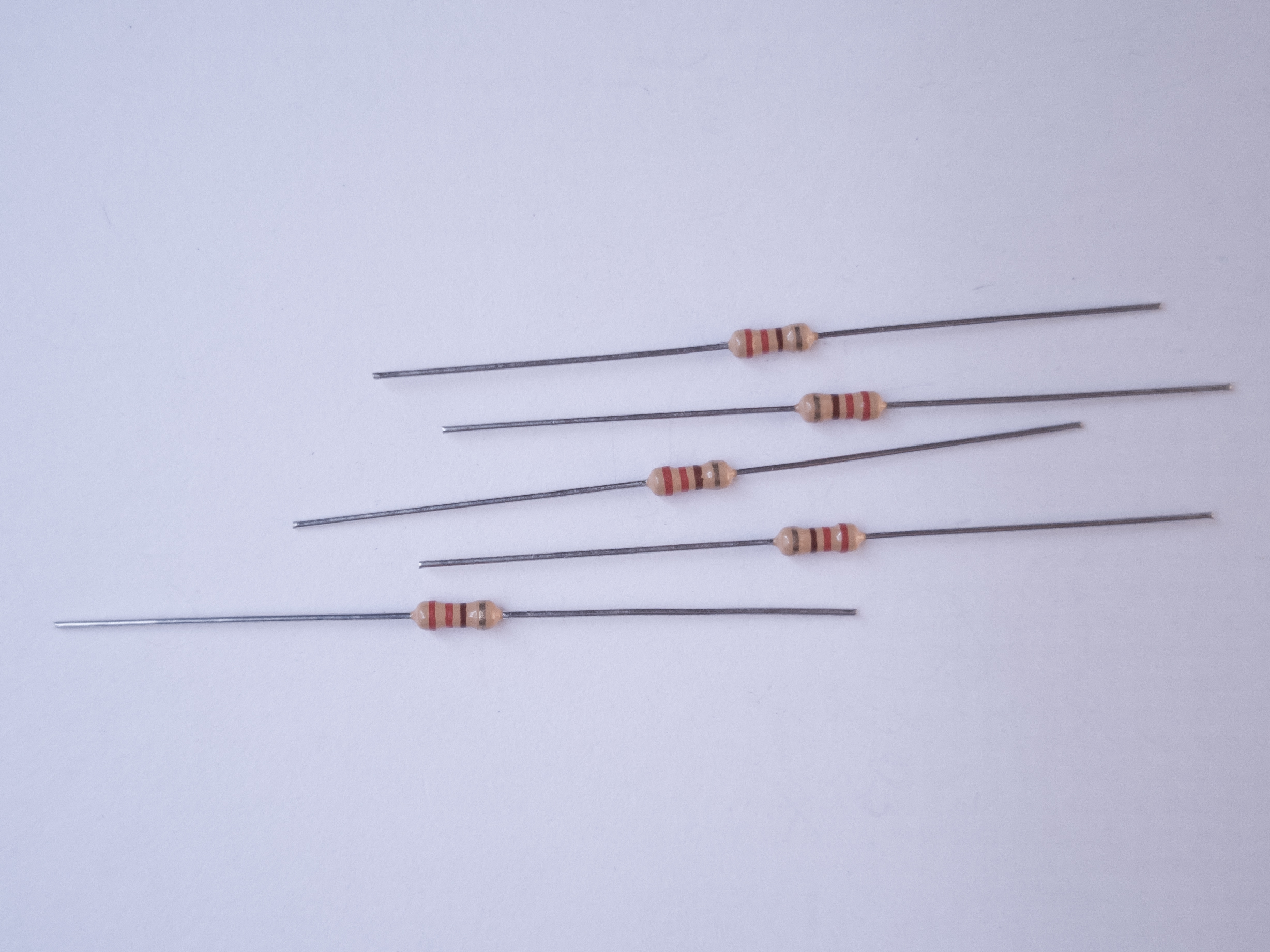
Figure 6. 220-ohm resistors (for the Uno version only)
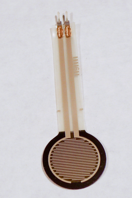
Figure 7. Force-sensing resistor
Figure 8. 10-kilohm resistors.
Figure 9. Pushbuttons
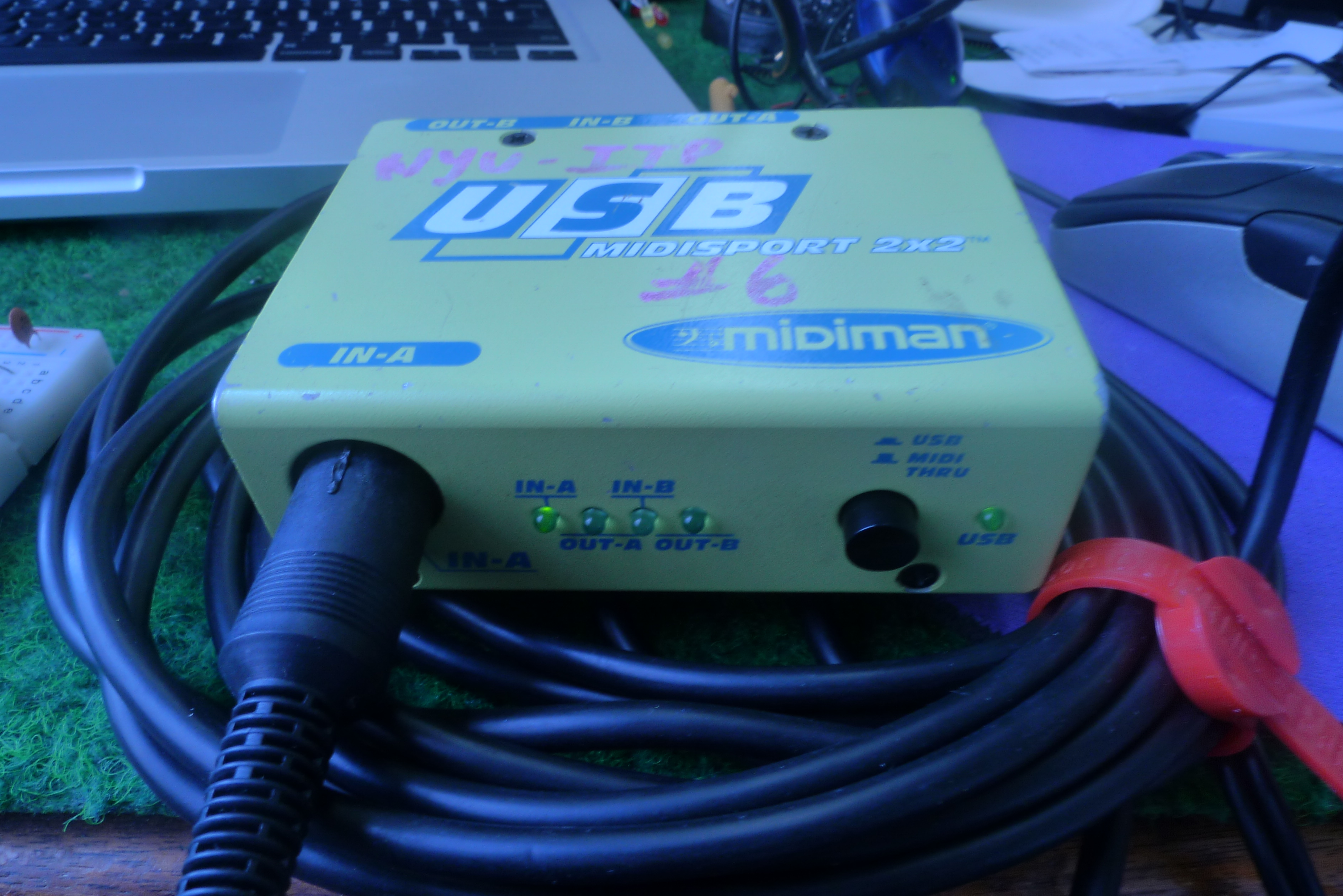
Figure 10. MIDISport 2×2 or other USB-to-MIDI interface (Serial versions only). ITP has some in the equipment room.
MIDI approaches: Serial, SoftwareSerial, or MIDIUSB
There are three approaches you can take to MIDI output, depending on the board you’re using and the application you have in mind.
If you’re communicating with a MIDI sound module like a synthesizer or sample, you’ll need to use either Serial or SoftwareSerial output. On the Uno, SoftwareSerial is best. On most other Arduino models, there is a second hardware serial port, Serial1, that you can use for MIDI output.
If you’re communicating with a MIDI program like Ableton, GarageBand, or a soundFont synth like Sforzando, either on a laptop or mobile device, then MIDIUSB is the way to go. The Uno can’t communicate using MIDIUSB, but the Nano 33 IoT, the MKR series, the Leonardo, Micro, or Due can.
SoftwareSerial Approach
If you’re using an Uno or any board with only one serial port, the SoftwareSerial library is your best bet. This section describes how to wire and program your board for SoftwareSerial.
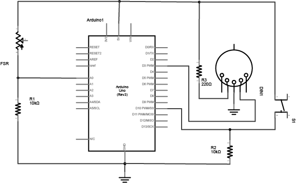
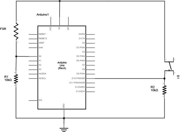
Figure 11. Schematic view of an Arduino connected to a voltage divider and a switch, with a MIDI connector as well.
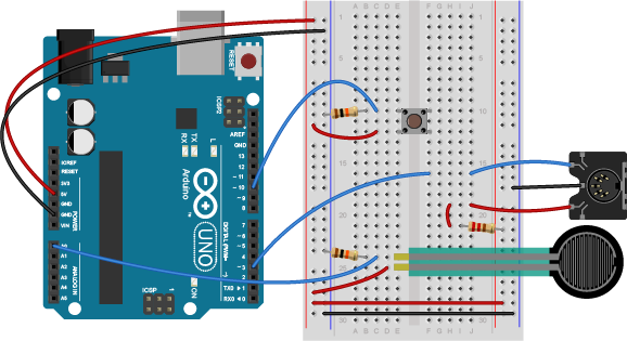
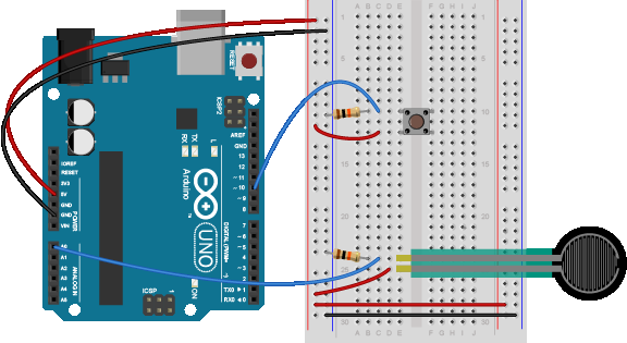
Figure 12. Breadboard view of an Arduino connected to a voltage divider, a switch, and a MIDI connector.
This circuit doesn’t actually match the MIDI specification, but it works with all the MIDI devices we’ve tried it with. This circuit includes an analog and a digital sensor to allow for physical interactivity, but those aren’t necessary to send MIDI data.
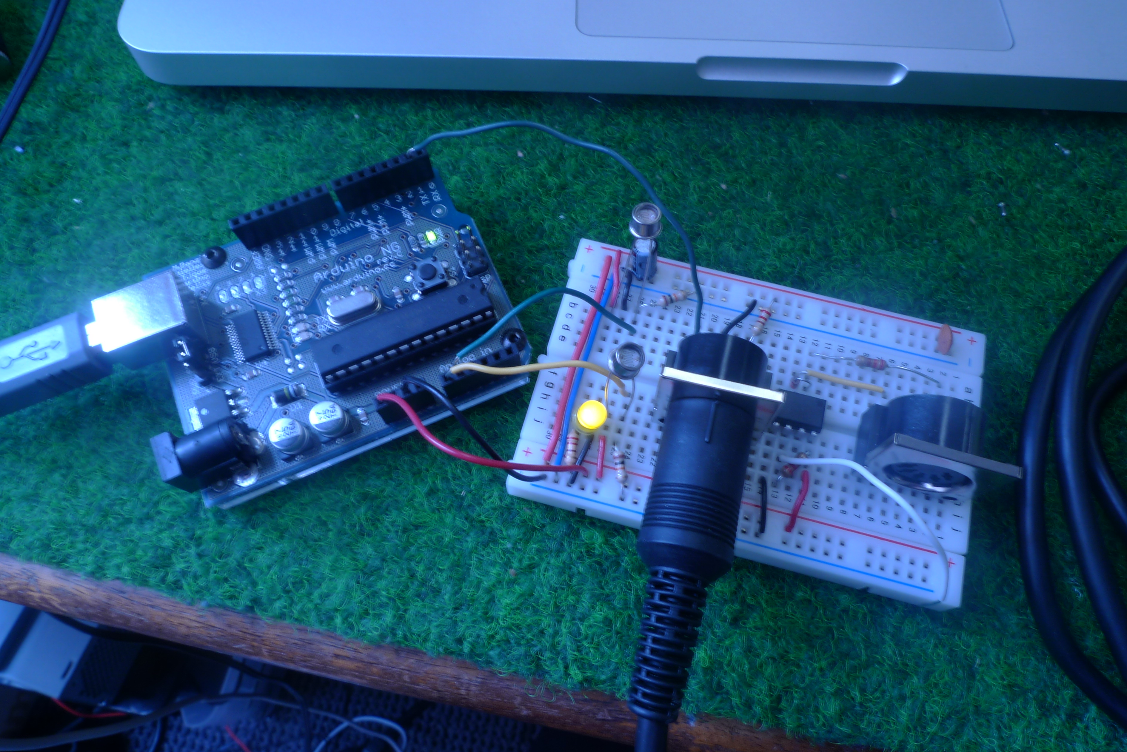
Figure 13. An Arduino MIDI circuit ready to play
Here we have a little Arduino instrument we whipped up using the MIDI Output Lab. It features two photocells, one controlling the pitch (or note being sent) and the other controlling the volume. Now that we are sending MIDI messages, we need to get them into the computer.
Figure 14. The MIDISport 2×2 USB-to-MIDI interface
USB-to-MIDI Interfaces
To get the MIDI messages into the computer, you will need a USB MIDI interface. A MIDISport 2×2 like the one pictured can be found in the Equipment Room. For more information see the technical details on the MIDISport. The interface connects to your computer via the USB cable and to the Arduino via a MIDI cable. Connect the Arduino to the MIDI In port of the interface.
Alternatively, you can use the MIDIUSB library to send MIDI via USB if you are using an ARM-based Arduino board like the MKR series. Doing so will eliminate the need for a USB-to-MIDI adapter like the MIDISport. Your Arduino will communicate directly with the computer as a MIDI device over USB.
Note on MIDIUSB and Serial Ports
The MIDIUSB library on the SAMD boards (MKRZero, MKR1xxx, Nano 33IoT) has an unusual behavior: using it changes the serial port enumeration. When you include the MIDIUSB library in a sketch, your board’s serial port number will change. For example, on MacOS, if the port number is /dev/cu.usbmodem14101, then adding the MIDIUSB library will change it to /dev/cu.usbmodem14102. Removing the MIDIUSB library will change it back to /dev/cu.usbmodem14101. Similarly, if you double-tap the reset button to put the board in bootloader mode, the serial port will re-enumerate to its original number.
Windows and MIDIUSB
You may have trouble getting these MIDI sketches to work on Windows. On Windows, the default Arduino drivers must be uninstalled so the system can recognize the Arduino as both serial device and MIDI device. Read this issue and follow the instructions there.
Audio MIDI Setup
To connect with your device on MacOS you’ll need the Audio MIDI Setup application. It’s in the Utilities directory of your Applications directory.
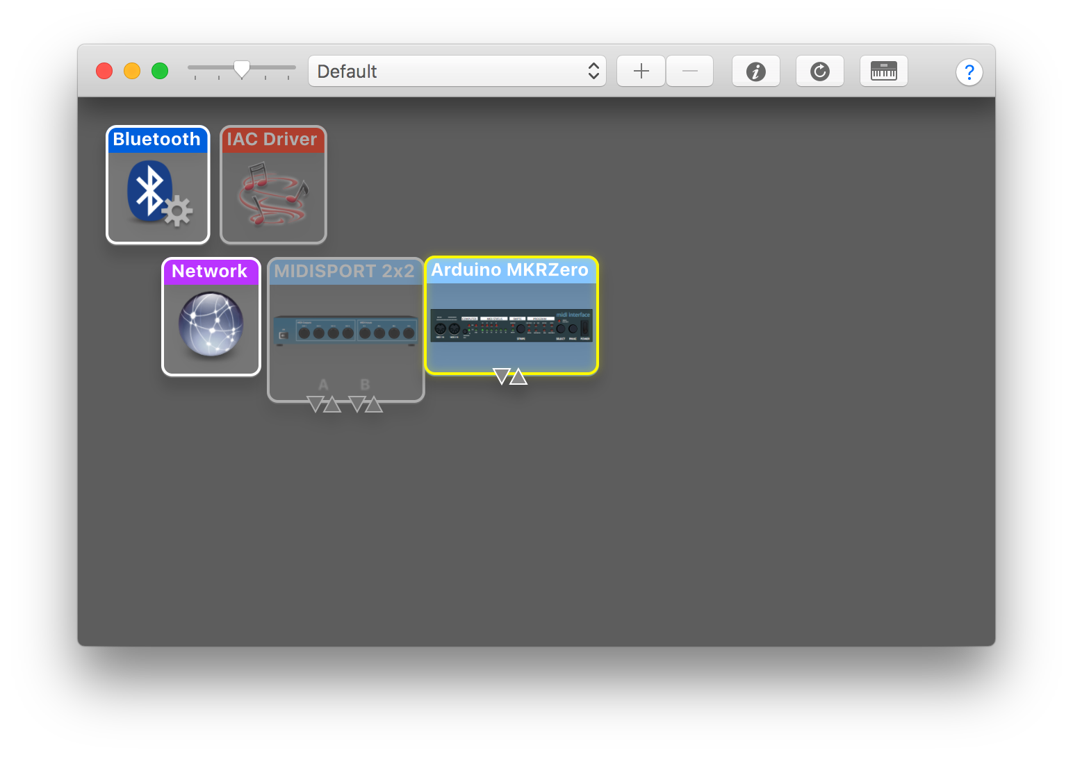
Figure 15. The Audio MIDI setup window in MacOS
If you’re not using the MIDIUSB library, you will need to download drivers for the MIDI interface you are using. Go to the manufacturer’s website (for example, M-Audio’s driver page, where you can find the MIDISport under MIDI Interfaces) and download the drivers that correspond to your interface and operating system. Once the drivers are installed, the interface should be recognized by your computer. To check this, open up Audio MIDI Setup. If you only see the Audio setup, click Window in your task bar and select Show MIDI Studio. You should then see the window pictured here and the interface should appear colored in. Interfaces that are not connected will appear faded as shown above.
Preferences in your DAW Software
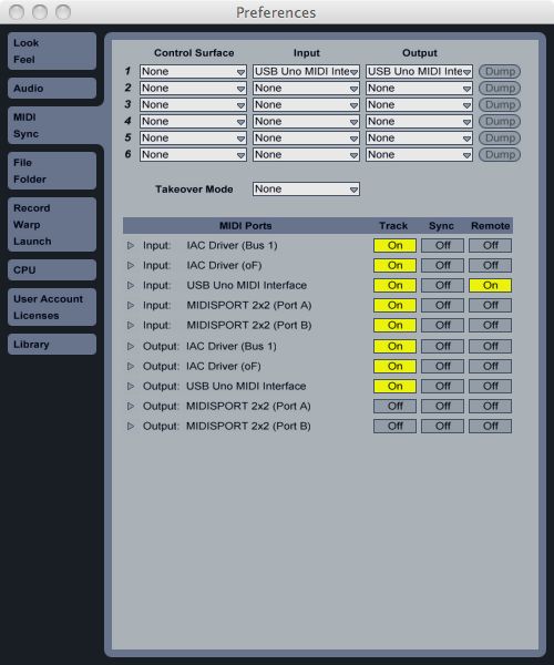
Figure 16. The MIDI Sync control panel in Ableton Live
Now that your computer recognizes the MIDI interface, you need to set up your preferences in the DAW. In this case, we are using Ableton Live so open up the preferences window. Ableton will recognize the interface but the ports need to be set. Find your interface and where it says Input, turn on the button listed under Track. Now Live will receive MIDI messages on these ports.
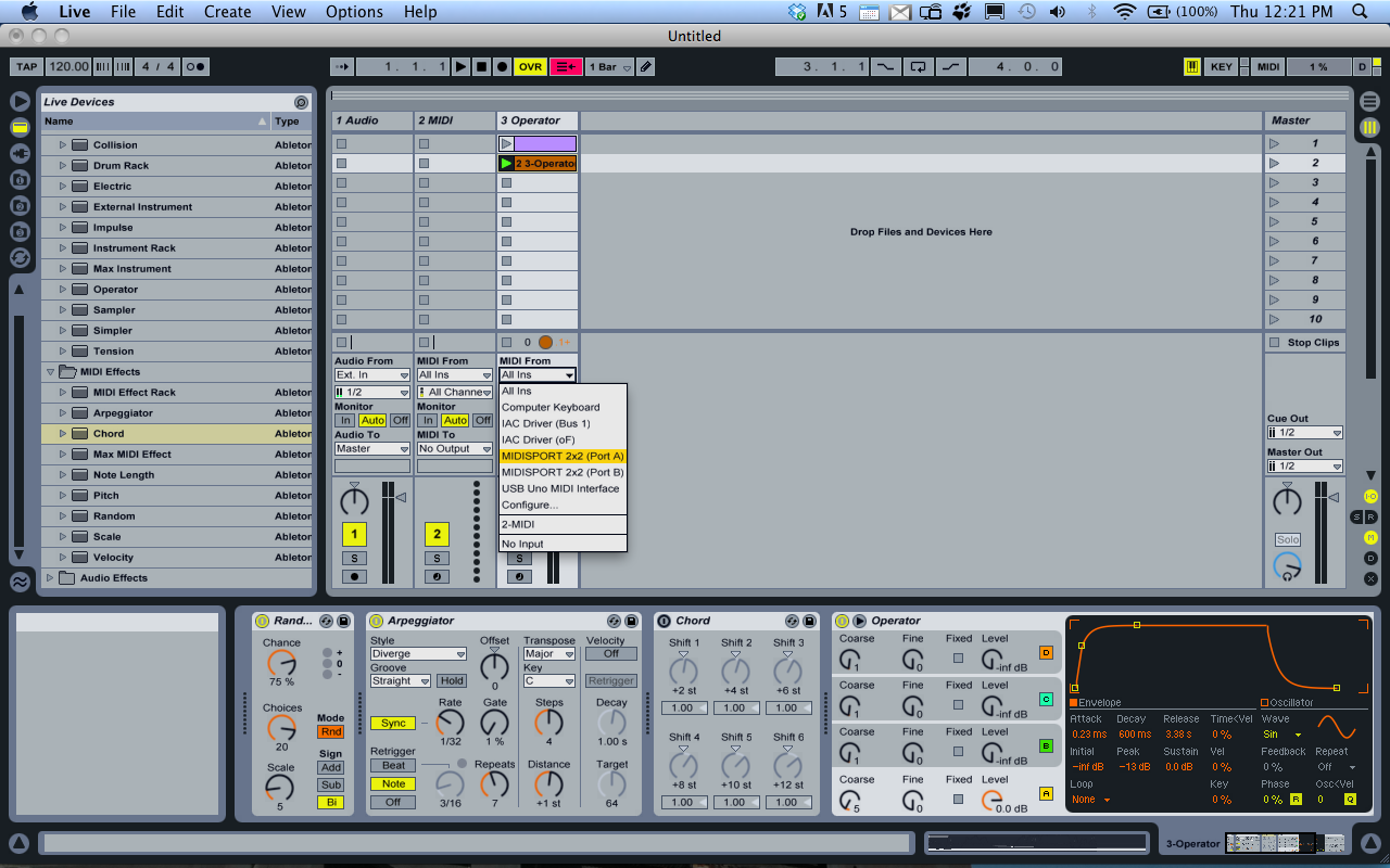
Figure 17. Screenshot of the Ableton Live Devices window
Select a MIDI track and add an instrument. Live has some instruments built in or you can use a third party plugin as a sound generator. In the screenshot above, the Operator FM synthesizer is selected. If you only have one device going in to Live, it is fine to leave the track’s MIDI input set to “All Ins.” If you have more than one, you will probably want to select a specific port as shown in the image above.
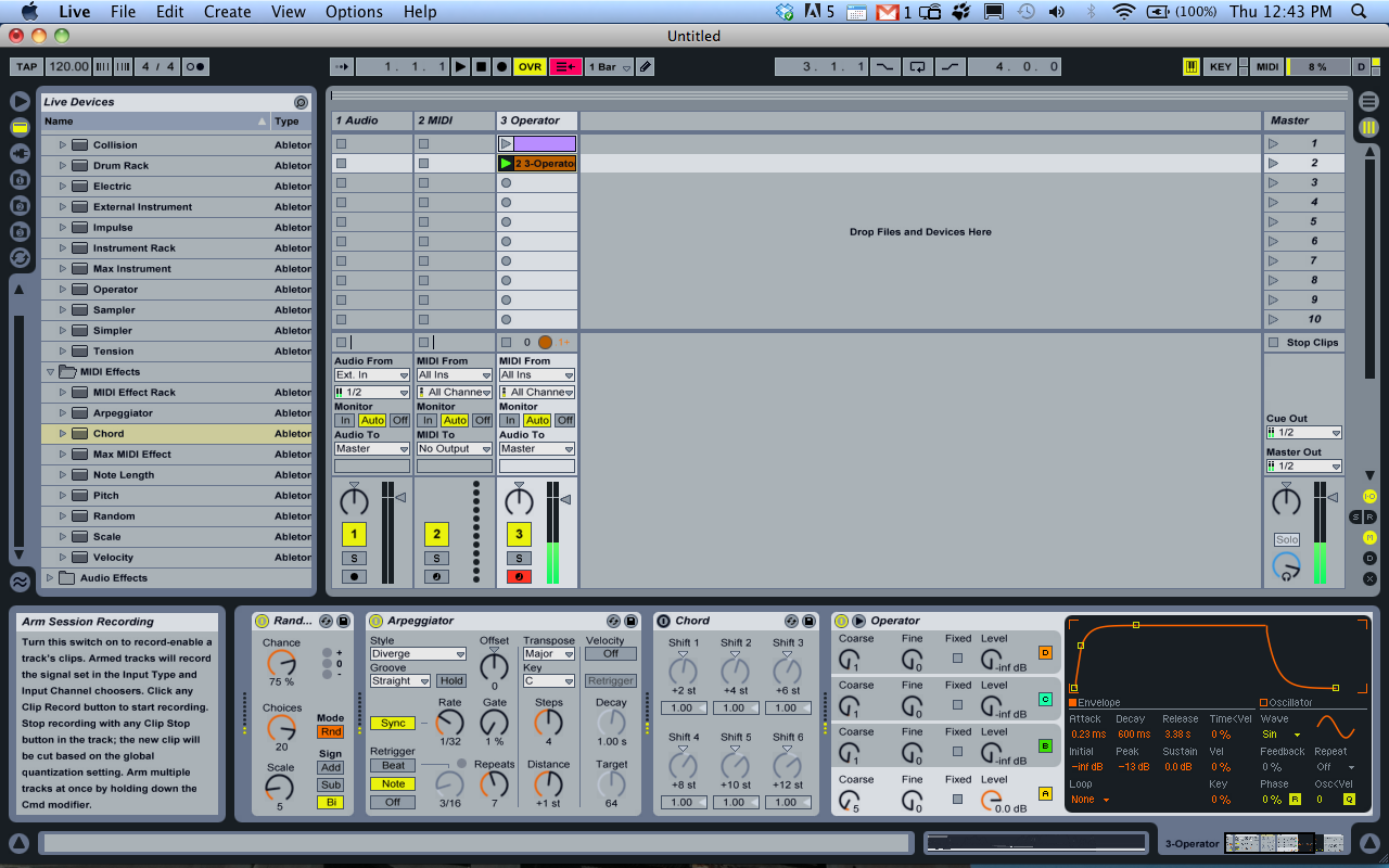
Figure 18. Arm your tracks with your MIDI inputs
The last step is to Arm the track by clicking the Arm button on the bottom of the channel strip. Now you are ready to go. Start sending MIDI from the Arduino and you should be hearing your lovely new instrument.
MIDI Monitor App
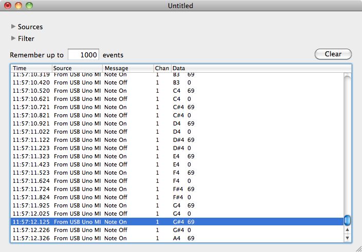
Figure 19. Snoize MIDI monitor is like a Serial Port monitor for MIDI
The Snoize MIDI monitor is a useful application to have if you do lots of MIDI input to your computer. You can download it from Snoize’s download page.
When running the application, MIDI Monitor will show you all the information that is coming in through the MIDI interface, such as the source, channel, message and note values. This is especially useful for debugging your MIDI instrument.
This lab covers only the details of MIDI communication on the Arduino module.
Introduction
This lab covers only the details of MIDI communication on the Arduino module. For a more general introduction to MIDI on a microprocessor, see the the MIDI notes.
MIDI, the Musical Instrument Digital Interface, is a useful protocol for controlling synthesizers, sequencers, and other musical devices. MIDI devices are generally grouped in to two broad classes: controllers (i.e. devices that generate MIDI signals based on human actions) and synthesizers (including samplers, sequencers, and so forth). The latter take MIDI data in and make sound, light, or some other effect.
What You’ll Need to Know
To get the most out of this lab, you should be familiar with the following concepts. You can check how to do so in the links below:
Figure 1-9 are the parts that you need for this lab.
Figure 1. A solderless breadboard.
Figure 2. 22 AWG hookup wire
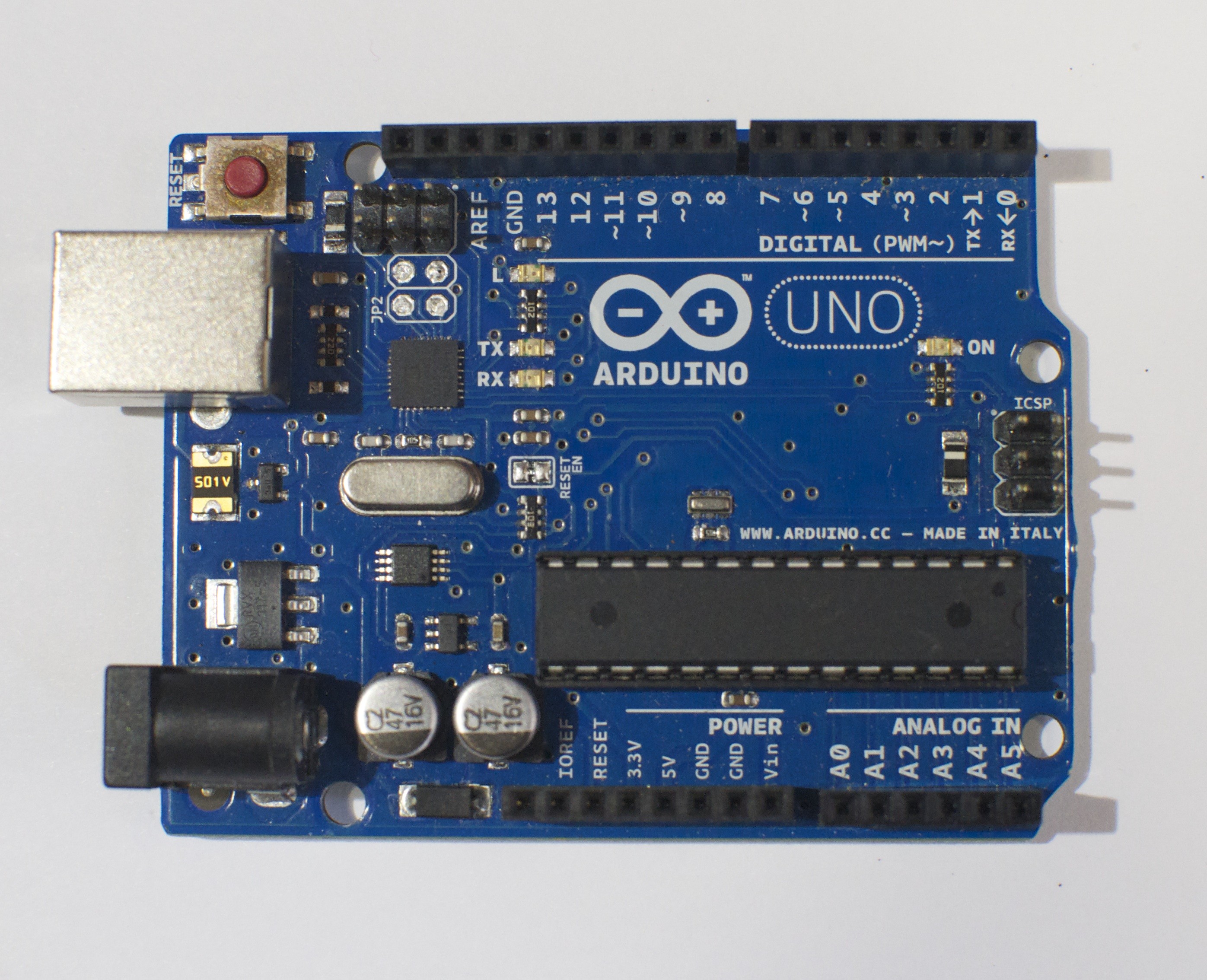
Figure 3. An Arduino Uno or…
Figure 4. Arduino Nano 33 IoT
Figure 5. A 5-pin MIDI socket (for the Uno version only)
Figure 6. 220-ohm resistors (for the Uno version only)
Figure 7. Force-sensing resistor
Figure 8. 10-kilohm resistors.
Figure 9. Pushbuttons
MIDI appoaches: Serial, SoftwareSerial, or MIDIUSB
There are three approaches you can take to MIDI output, depending on the board you’re using and the application you have in mind.
If you’re communicating with a MIDI sound module like a synthesizer or sampler, you’ll need to use either Serial or SoftwareSerial output. On the Uno, SoftwareSerial is best. On most other Arduino models, there is a second hardware serial port, Serial1, that you can use for MIDI output.
If you’re communicating with a MIDI program like Ableton, GarageBand, or a soundFont synth like Sforzando, either on a laptop or mobile device, then MIDIUSB is the way to go. The Uno can’t communicate using MIDIUSB, but the Nano 33 IoT, the MKR series, the Leonardo, Micro, or Due can.
SoftwareSerial Approach
If you’re using an Uno or any board with only one serial port, the SoftwareSerial library is your best bet. This section describes how to wire and program your board for SoftwareSerial.
Prepare the breadboard
Connect power and ground on the breadboard to power and ground from the microcontroller. On the Arduino module, use the 5V and any of the ground connections (Figure 10):
Figure 10. An Arduino Uno on the left connected to a solderless breadboard, right.
For the Nano 33 IoT version or any of the MIDIUSB versions (see below), you won’t need a MIDI jack.
Connect the sensors
Connect an analog sensor to analog pins 0 like you did in the analog lab (Figure 11). Connect a switch to digital pin 10 like you did in the digital lab (Figure 12).
Figure 11. Schematic view of an Arduino connected to a voltage divider and a switch.
Figure 12. Breadboard view of an Arduino connected to a voltage divider and a switch.
Build the MIDI Circuit
Add the MIDI out jack and a 220-ohm resistor to digital pin 3, as shown in Figure 13-14:
Figure 13. Schematic view of an Arduino connected to a voltage divider and a switch, with a MIDI connector as well.
Figure 14. Breadboard view of an Arduino connected to a voltage divider, a switch, and a MIDI connector.
This circuit doesn’t actually match the MIDI specification, but it works with all the MIDI devices we’ve tried it with. This circuit includes an analog and a digital sensor to allow for physical interactivity, but those aren’t necessary to send MIDI data.
Play Notes
Once you’re connected, sending MIDI is just a matter of sending the appropriate bytes. In the code below, you’ll use the SoftwareSerial library to send data on digital pin 3, so that you can keep the hardware serial available for debugging purposes.
The bytes have to be sent as binary values, but you can format them in your code as decimal or hexadecimal values. The example below uses hexadecimal format for any fixed values, and a variable for changing values. All values are sent serially as raw binary values, using the BYTE modifier to .print() (Many MIDI tables give the command values in hex, so this was done in hex for the sake of convenience):
#include"SoftwareSerial.h"

 // Variables:
  byte note = 0;            // The MIDI note value to be played

 //software serial
 SoftwareSerial midiSerial(2, 3); // digital pins that we'll use for soft serial RX and TX

  void setup() {
    //  Set MIDI baud rate:
    Serial.begin(9600);
    midiSerial.begin(31250);
  }

  void loop() {
    // play notes from F#-0 (30) to F#-5 (90):
    for (note = 30; note < 90; note ++) {
      //Note on channel 1 (0x90), some note value (note), middle velocity (0x45):
      noteOn(0x90, note, 0x45);
      delay(100);
      //Note on channel 1 (0x90), some note value (note), silent velocity (0x00):
      noteOn(0x90, note, 0x00);
      delay(100);
    }
  }

  //  plays a MIDI note.  Doesn't check to see that
  //  cmd is greater than 127, or that data values are  less than 127:
  void noteOn(byte cmd, byte data1, byte data2) {
    midiSerial.write(cmd);
    midiSerial.write(data1);
    midiSerial.write(data2);

     //prints the values in the serial monitor so we can see what note we're playing
    Serial.print("cmd: ");
    Serial.print(cmd);
    Serial.print(", data1: ");
    Serial.print(data1);
    Serial.print(", data2: ");
    Serial.println(data2);
  }
Alternatives to SoftwareSerial
There are two alternatives to SoftwareSerial, but they are only available on boards other than the Uno. You could use the second hardware serial port if you have one. Or, if you’re using one of the MKR series boards or a Nano 33 IoT or an M0-based derivative board, you can use MIDIUSB.
Second Hardware Serial Port
If you’re using any board that has two hardware serial ports, you don’t have to use SoftwareSerial. That includes almost any of the official Arduino boards except the Uno: the Nano 33 IoT, the Due, the Mega, the MKR series, the Leonardo, the Micro and the 101 all have two hardware serial ports. You could also use any M0- or 32U4-based derivative board like Adafruit’s Feather and Trinket boards. If you are using one of those boards, copy the circuits above but move the MIDI connector’s pin 4 to the TX1 pin of your board. Then change your code as follows. First, remove the first line that includes the SoftwareSerial library. Then remove the line that initializes SoftwareSerial. Then change midiSerial.begin() to Serial1.begin(). Then change all midiSerial calls to Serial1 calls. Here’s the changed code:
// Variables:
byte note = 0; // The MIDI note value to be played

void setup() {
  // Set MIDI baud rate:
  Serial.begin(9600);
  Serial1.begin(31250);
}

void loop() {
  // play notes from F#-0 (30) to F#-5 (90):
  for (note = 30; note < 90; note ++) {
    // Note on channel 1 (0x90), some note value (note), middle velocity (0x45):
    noteOn(0x90, note, 0x45);
    delay(100);
    // Note on channel 1 (0x90), some note value (note), silent velocity (0x00):
    noteOn(0x90, note, 0x00);
    delay(100);
  }
}

// plays a MIDI note. Doesn't check to see that
// cmd is greater than 127, or that data values are less than 127:
void noteOn(byte cmd, byte data1, byte data2) {
  Serial1.write(cmd);
  Serial1.write(data1);
  Serial1.write(data2);

  //prints the values in the serial monitor so we can see what note we're playing
  Serial.print("cmd: ");
  Serial.print(cmd);
  Serial.print(", data1: ");
  Serial.print(data1);
  Serial.print(", data2: ");
  Serial.println(data2);
}
Using MIDIUSB
If you’re using an ARM board like the MKR series, the Nano 33 IoT, the Due, or any of the M0-based derivatives, you can also use MIDIUSB. When you do this, your microcontroller shows up to your computer like a USB MIDI device. This is handy for when you’re connecting to a laptop. It’s less handy for connecting to dedicated synthesizers or samplers.
To do this, dispose of the MIDI socket. You’ll be connecting through your USB connector, and yes, the serial connection to the Serial Monitor will still work as well. Change your code as follows. First include the MIDIUSB library (you might need to install it using the Library Manager) at the top of your code. Then remove the Serial1.begin() line in the setup. Then replace the Serial1.write() lines in the noteOn function with the MIDI code shown below:
  #include "MIDIUSB.h"
  // Variables:
  byte note = 0;            // The MIDI note value to be played

  void setup() {
    Serial.begin(9600);
  }

  void loop() {
    // play notes from F#-0 (30) to F#-5 (90):
    for (note = 30; note < 90; note ++) {
      //Note on channel 1 (0x90), some note value (note), middle velocity (0x45):
      noteOn(0x90, note, 0x45); delay(100);
      //Note on channel 1 (0x90), some note value (note), silent velocity (0x00):
      noteOn(0x90, note, 0x00); delay(100);
     }
   }

   // plays a MIDI note. Doesn't check to see that
   // cmd is greater than 127, or that data values are less than 127:
   void noteOn(byte cmd, byte data1, byte data2) {
     /* First parameter is the event type (top 4 bits of the command byte).
        Second parameter is command byte combined with the channel.
        Third parameter is the first data byte
        Fourth parameter second data byte, if there is one:
    */
    midiEventPacket_t midiMsg = {cmd >> 4, cmd, data1, data2};
    MidiUSB.sendMIDI(midiMsg);

    //prints the values in the serial monitor so we can see what note we're playing
    Serial.print("cmd: ");
    Serial.print(cmd);
    Serial.print(", data1: ");
    Serial.print(data1);
    Serial.print(", data2: ");
    Serial.println(data2);
  }
Note on MIDIUSB and Serial Ports
The MIDIUSB library on the SAMD boards (MKRZero, MKR1xxx, Nano 33IoT) has an unusual behavior: using it changes the serial port enumeration. When you include the MIDIUSB library in a sketch, your board’s serial port number will change. For example, on MacOS, if the port number is /dev/cu.usbmodem14101, then adding the MIDIUSB library will change it to /dev/cu.usbmodem14102. Removing the MIDIUSB library will change it back to /dev/cu.usbmodem14101. Similarly, if you double-tap the reset button to put the board in bootloader mode, the serial port will re-enumerate to its original number.
Windows and MIDIUSB
You may have trouble getting these MIDI sketches to work on Windows. On Windows, the default Arduino drivers must be uninstalled so the system can recognize the Arduino as both serial device and MIDI device. Read this issue and follow the instructions there.
Allow a Person to Play Notes
The previous example will just play notes, no interactivity. The example below uses an analog input to set the pitch, and a digital input (a switch) to start and stop the note:
 #include "SoftwareSerial.h"

 const int switchPin = 10;  // The switch is on Arduino pin 10
 const int LEDpin = 13;     //  Indicator LED

  // Variables:
  byte note = 0;              // The MIDI note value to be played
  int AnalogValue = 0;        // value from the analog input
  int lastNotePlayed = 0;     // note turned on when you press the switch
  int lastSwitchState = 0;    // state of the switch during previous time through the main loop
  int currentSwitchState = 0;

 //software serial
 SoftwareSerial midiSerial(2, 3); // digital pins that we'll use for soft serial RX and TX

  void setup() {
    //  set the states of the I/O pins:
    pinMode(switchPin, INPUT);
    pinMode(LEDpin, OUTPUT);
    //  Set MIDI baud rate:
    Serial.begin(9600);
    midiSerial.begin(31250);
  }

  void loop() {
    //  My potentiometer gave a range from 0 to 1023:
    AnalogValue = analogRead(0);
    //  convert to a range from 0 to 127:
    note = AnalogValue/8;
    currentSwitchState = digitalRead(switchPin);
    // Check to see that the switch is pressed:
    if (currentSwitchState == 1) {
      //  check to see that the switch wasn't pressed last time
      //  through the main loop:
      if (lastSwitchState == 0) {
        // set the note value based on the analog value, plus a couple octaves:
        // note = note + 60;
        // start a note playing:
        noteOn(0x90, note, 0x40);
        // save the note we played, so we can turn it off:
        lastNotePlayed = note;
        digitalWrite(LEDpin, HIGH);
      }
    }
    else {   // if the switch is not pressed:
      //  but the switch was pressed last time through the main loop:
      if (lastSwitchState == 1) {
        //  stop the last note played:
        noteOn(0x90, lastNotePlayed, 0x00);
        digitalWrite(LEDpin, LOW);
      }
    }

    //  save the state of the switch for next time
    //  through the main loop:
    lastSwitchState = currentSwitchState;
  }

  //  plays a MIDI note.  Doesn't check to see that
  //  cmd is greater than 127, or that data values are  less than 127:
  void noteOn(byte cmd, byte data1, byte  data2) {
    midiSerial.write(cmd);
    midiSerial.write(data1);
    midiSerial.write(data2);

   //prints the values in the serial monitor so we can see what note we're playing
    Serial.print("cmd: ");
    Serial.print(cmd);
    Serial.print(", data1: ");
    Serial.print(data1);
    Serial.print(", data2: ");
    Serial.println(data2);
  }
Make an Instrument
Now that you’ve got the basics, make a musical instrument. Consider a few things in designing your instrument:
Do you want to play discrete notes (like a piano), or sliding pitches (like a theremin)? How do you program to achieve these effects?
Do you want to control the tempo and duration of a note?
Do you want the same physical action to set both the pitch and the velocity (volume) of a note?
Do you want to be able to play more than one note at a time (e.g. chords)?
All of these questions, and many more, will affect what sensors you use, how you read them, and how you design both the physical interface and the software.
Arduino Nano 33 IoTFlexible jumper wires. These wires are quick for breadboard prototyping, but can get messy when you have lots of them on a board.A solderless breadboard with two rows of holes along each side. The . board is turned sideways so that the side rows are on top and bottom in this view. There are no components mounted on the board. Photo of an 8 ohm speaker10-kilohm resistors. These ones are 5-band resistors 100-ohm to 220-ohm resistors. The ones shown here are are 4-band 220-ohm resistors. They are colored red, red, brown and gold, which signifies 2, 2 (red, red), times 10 (brown), with a 5% tolerance (gold).Force Sensing Resistor (FSR)Figures 1-7. The parts you’ll need for this exercise. Click on any image for a larger view.
Sound is created by vibrations in air. When those vibrations get fast enough, above about 20 times a second, you hear them as an audible pitch. The number of vibrations per second is called the frequency and frequency is measured in Hertz (Hz). So 20 times a second is 20Hz. Humans can hear pitches from about 20Hz to about 20,000Hz, or 20 kiloHertz (kHz).
What vibrations are we talking about? A speaker can vibrate. The paper cone of the speaker moves forward, then backward, then back to its resting place many times a second. The length of time it takes to move from rest through one back-and-forth motion, is called the period of the vibration. For example, if a speaker is vibrating at 20Hz, then it moves forward, backward, and back to rest 2in 1/20 of a second, or 0.05 seconds. 0.05 seconds is the period of the sound. Period and frequency are related inversely: frequency = 1/period.
A microcontroller makes sound by sending pulses of electrical energy from an output pin through a wire that’s connected to the paper cone of a speaker. That wire is wrapped in a coil, and mounted inside a magnet. The electrical energy generates a magnetic field, and that field is either attracted to the magnet or repelled by it, depending on which direction the electrical energy is flowing. The magnetic energy moves the coil, and since the coil is attached to the cone, the speaker moves.
So in summary: how do you make sound from an Arduino? Attach a speaker to an output pin and turn it on and off at a set frequency. You can write this code yourself, or you can use the tone() command.
Pulsewidth Modulation vs. Frequency Modulation
When you use analogWrite() to create pulsewidth modulation (PWM) on an output pin, you’re also turning the pin on and off, so you might think, “why not use analogWrite() to make tones?” That command can change the on-off ratio of the output (also known as the duty cycle) but not the frequency. If you have a speaker connected to an output pin running analogWrite(), you’ll get a changing loudness, but a constant tone. To change the tone, you need to change the frequency. The tone() command does this for you.
Prepare the breadboard
Connect power and ground on the breadboard to the microcontroller. On the Arduino module, use the 5V or 3.3V (depending on your model) and any of the ground connections. Figures 8 and 9 show connections for an Arduino Uno and a Nano, respectively.
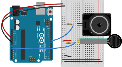
Figure 8. Breadboard view of an Arduino Uno on the left connected to a solderless breadboard, right.
The Uno’s 5V output hole is connected to the red column of holes on the far left side of the breadboard (Figure 8). The Uno’s ground hole is connected to the blue column on the left of the board. The red and blue columns on the left of the breadboard are connected to the red and blue columns on the right side of the breadboard with red and black wires, respectively. These columns on the side of a breadboard are commonly called the buses. The red line is the voltage bus, and the black or blue line is the ground bus.
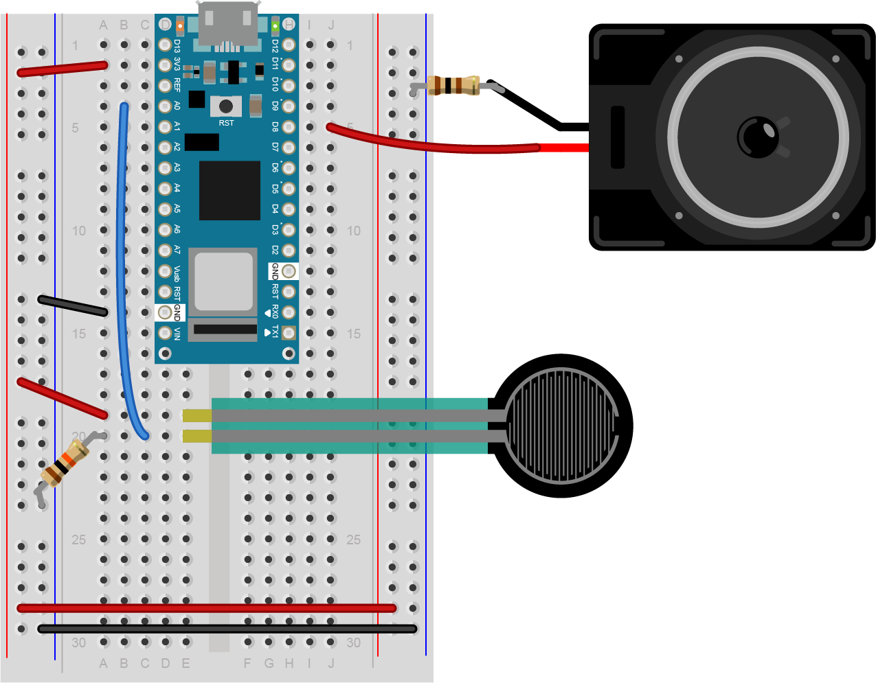
Figure 9. Breadboard view of an Arduino Nano mounted on a solderless breadboard.
In Figure 9, the Nano is mounted at the top of the breadboard, straddling the center divide, with its USB connector facing up. The top pins of the Nano are in row 1 of the breadboard.
The Nano, like all Dual-Inline Package (DIP) modules, has its physical pins numbered in a U shape, from top left to bottom left, to bottom right to top right. The Nano’s 3.3V pin (physical pin 2) is connected to the left side red column of the breadboard. The Nano’s GND pin (physical pin 14) is connected to the left side black column. These columns on the side of a breadboard are commonly called the buses. The red line is the voltage bus, and the black or blue line is the ground bus. The blue columns (ground buses) are connected together at the bottom of the breadboard with a black wire. The red columns (voltage buses) are connected together at the bottom of the breadboard with a red wire.
Connect a variable resistor such as a force-sensing resistor or photosensor to analog pin 0 in a voltage divider circuit as shown below. The 8-ohm speaker connects to pin 8 of the Arduino. You can use any digital I/O pin if you don’t like 8. The other end of the speaker connects to ground. Figures 10 through 12 show the schematic drawing and the breadboard layouts for an Uno and a Nano, respectively.
Note: Although the circuit shown in Figures 10-12 has a 100-ohm resistor with the speaker, you can use a larger resistor. The larger the resistor, the quieter the speaker. A 220-ohm resistor works reasonably well if you don’t have a 100-ohm resistor.
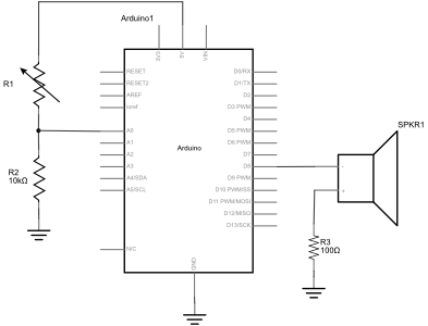
Figure 10. Schematic view of an Arduino connected to a force sensing resistor (FSR), a 10-kilohm resistor, and a speaker. One leg of the FSR is connected to voltage. The other leg is connected simultaneously to the first leg of a 10-kilohm resistor and the Arduino’s analog input pin A0. The second leg of the 10-kilohm resistor is connected to ground. The red positive wire of the speaker is connected to digital pin 8 of the Arduino. The black ground wire of the speaker is connected to one leg of a 100 ohm resistor. The other leg of the resistor connects to ground.
Figure 11. Breadboard view of an Arduino connected to a force-sensing resistor, a fixed resistor, and a speaker. The Arduino’s voltage out and ground pins are connected to the voltage and ground buses of the breadboard as usual. The FSR is mounted in the left center section of the breadboard. One leg of the FSR is connected to 5 volts. The other leg is connected simultaneously to the first leg of a 10-kilohm resistor and the Arduino’s analog input pin A0. The second leg of the 10-kilohm resistor is connected to ground. The red positive wire of the speaker is connected to digital pin 8 of the Arduino. The black ground wire of the speaker is connected to one leg of a 100 ohm resistor. The other leg of the resistor connects to ground.
Figure 12. Breadboard view of an Arduino Nano connected to two force sensing resistors (FSRs) and a speaker. The Nano’s 3.3 Volts (physical pin 2) and ground (physical pin 14) are connected to the voltage and ground buses of the breadboard as usual. The FSR is mounted below the Nano in the left center section of the breadboard. One leg of the FSR is connected to voltage. The other leg is connected simultaneously to the first leg of a 10-kilohm resistor and the Arduino’s analog input pin A0. The second leg of the 10-kilohm resistor is connected to ground. The red positive wire of the speaker is connected to digital pin 8 of the Arduino. The black ground wire of the speaker is connected to one leg of a 100 ohm resistor. The other leg of the resistor connects to ground.
Once you’ve got the circuit connected, check the range of the analog input and note the highest and lowest values you can reach.
void setup() {
  Serial.begin(9600);       // initialize serial communications
}

void loop() {
  int analogValue = analogRead(A0); // read the analog input
  Serial.println(analogValue);      // print it
}
Once you know the range, take note of it for when you map it to the tone range you want, as you’ll see below. The example here assumes a sensor range from 200 to 900, but your sensor range might be different.
Check that the Speaker Works
You can check that the speaker works by playing a single tone over and over. Here’s a short sketch to play middle A, 440Hz:
void setup() {
  // nothing to do here
}

void loop() {
  // play the tone for 1 second:
  tone(8, 440,1000);
  // do nothing else for the one second you're playing:
  delay(1000);
}
When you run this sketch, you should hear a tone of 44oHz, or middle A, continually. If you don’t, check to see that your speaker wiring is as shown above. If it’s too soft, try changing the 100 Ohm resistor to a smaller resistor.
Play Tones
Write a sketch to read the analog input and map the result to a range from 100 to 1000. The example below assumes your analog input circuit ranges from 200 to 900, so adjust for your actual values. Store the result in a local variable called frequency. This will be the frequency you play on the speaker. Then use the tone() command to set the frequency of the speaker on pin 8.
void setup() {
  // nothing to do here
}

void loop() {
  // get a sensor reading:
  int sensorReading = analogRead(A0);
  // map the results from the sensor reading's range
  // to the desired pitch range:
  float frequency = map(sensorReading, 200, 900, 100, 1000);
  // change the pitch, play for 10 ms:
  tone(8, frequency, 10);
  delay(10);
}
My sensor values are all crazy! I’m not getting a 200 to 900 range! Remember, you may need to find your individual sensor value ranges before you decide on the mapping range. Again, this example assumes your analog input circuit ranges from 200 to 900. You can also constrain the output range after you map it, to make sure it’s giving you only the range you want, like so:
frequency = constrain(frequency, 10, 1000); // do this after the map() command
Once you’ve uploaded this, move your hands over the photocells, and listen to the frequency change. It will change from 100 Hz to 1000 HZ, because that’s what you set in the map() command. If you want to change the frequency range, change those two numbers. See if you can get it to play a little tune.
If you want to know how to generate a tone without the tone() command, here’s the basic algorithm to play one wavelength:
void makeTone(float frequency) {
  // set the period in microseconds:
  int period = (1 / frequency) * 1000000;
  // turn the speaker on:
  digitalWrite(speakerPin, HIGH);
  // delay half the period:
  delayMicroseconds(period / 2);
  // turn the speaker off:
  digitalWrite(speakerPin, LOW);
  // delay half the period:
  delayMicroseconds(period / 2);
}
Play it Loud
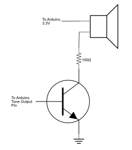
If you’d like to amplify the speaker, modify the speaker circuit by adding a transistor. Most any NPN transistor circuit or N-channel MOSFET will do. Figure 13 shows a speaker getting power from a transistor. This example uses a TIP120 transistor, but an NPN transistor or N-channel MOSFET should work. When using a transistor to amplify the power going to the speaker, you should definitely use a resistor to limit the current. A 100-ohm resistor is shown in this example.
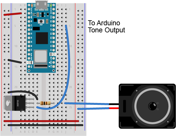
Figure 13. Schematic view of a speaker connected to a transistor. The first leg of the speaker connects to the Arduino’s voltage supply (3.3V). The second leg of the speaker connects to a10-0-ohm resistor. The other side leg of the resistor connects to the collector pin of an NPN transistor (for a TIP120 transistor, this is the middle pin). The transistor’s base pin (the pin to the left when the transistor’s body is facing you) connects to the Arduino’s tone output pin (pin 8 in the examples above). The transistor’s collector pin (on the right when the transistor is facing you) connects to ground. Figure 14. Breadboard view of a speaker connected to a transistor. The speaker and transistor are connected exactly as described in the schematic view caption in Figure 13.
Note: the transistor shown in this circuit, a TIP120, looks the same as some of the other components you’ve used, like the 7805 regulator. When two components have the same form factor, it’s referred to as the same package. You can read more on this in the Components lab.
Use Headphones
You can also connect the tone output of an Arduino to headphones. Using a standard 3.5mm audio jack, connect the center pin of the jack to ground through a 10-kilohm resistor. Then connect the two sides to each other and to your tone output pin. The 10-kilohm resistor here is important, because without it the audio signal will be too strong for your headphones, and could cause you ear damage. Figure 15 shows an audio jack connected to an Arduino Nano 33 IoT for the examples shown here.
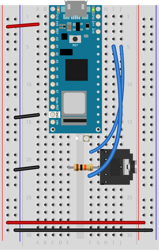
Figure 15. Breadboard view of a 3.5mm Audio jack connected to an Arduino Nano 33 IoT. The center pin of the audio jack is connected to ground through a 10-kilohm resistor. The two sides are connected to the Nano 33’s tone output pin, which is pin 8 in this example.
A more complex example
There’s an example in the Arduino IDE examples that can play a melody for you. Look in the File Menu under Examples -> Digital -> ToneMelody. You can find the code online at this link. In this example, you’ll see a second tab of text called pitches.h. This file includes constants that give you the pitches for a standard western scale.
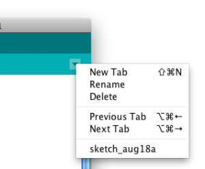
You can add your own extra tabs using the new Tab menu to the right of the IDE window. Figure 16 shows the new Tab dropdown menu. Tabs make it easier to separate frequently copied code from custom code for a sketch, as you see in this example.
Figure 16. A dropdown menu located in the upper right hand corner of the Arduino IDE showing the tab options. You can also type cmmand-shift-N to get a new tab.
You’ll notice that pitches.h lists a number of note names and numbers. Those numbers are the frequency of each note. For example:
This tells you that that first note in the list, B0 (which is the second lowest note on a piano keyboard, 4 octaves below middle A) has a frequency of 31 Hz. The values listed in pitches.h allow you to play notes from B0 to D#8.
For this sketch, you’ll play a simple melody. A melody consists of notes played in a sequence, and rests between the note. Each note and rest has its own particular duration. You’re going to play a seven note sequence, as shown in Figure 17 (in C Major):
Figure 17. Two measures of a musical notation. The melody is “Shave and a haircut, two bits”
image from seventhstring.com
The sequence is: C4, G3, G3, G#3, G3, rest, B3, C4
The sketch starts with two global variables. Using pitches.h, make an array variable holding those notes. Make a second array to hold the note durations, marking quarter notes as 4 and eighth notes as 8.
// notes in the melody:
int melody[] = {
NOTE_C4, NOTE_G3,NOTE_G3, NOTE_GS3, NOTE_G3,0, NOTE_B3, NOTE_C4};

// note durations: 4 = quarter note, 8 = eighth note, etc.:
int noteDurations[] = {
4, 8, 8, 4,4,4,4,4 };
How can you use the durations to play notes? Well, imagine that a quarter note is one quarter of a second, and eighth note is one eighth of a second, and so forth. In that case, the actual duration for each note is 1000 milliseconds divided by the value for it in the durations array. For example, the first note is 1000/4, the second is 1000/8, and so forth.
Now, you only want to play the song once, so everything will happen in the setup(). You’ll make a for loop in the setup to iterate over the seven notes. For each time through the loop, use tone() to play the next note in the array. Use the formula in the last paragraph to determine how long each note should play for. After you start the note, delay for as long as the note plays, plus 30 milliseconds or so, to separate each note.
#include "pitches.h"

// notes in the melody:
int melody[] = {
NOTE_C4, NOTE_G3,NOTE_G3, NOTE_GS3, NOTE_G3,0, NOTE_B3, NOTE_C4};

// note durations: 4 = quarter note, 8 = eighth note, etc.:
int noteDurations[] = {4,8,8,4,4,4,4,4 };

void setup() {
  // iterate over the notes of the melody:
  for (int thisNote = 0; thisNote < 8; thisNote++) {
    // to calculate the note duration, take one second
    // divided by the note type.
    //e.g. quarter note = 1000 / 4, eighth note = 1000/8, etc.
    int noteDuration = 1000/noteDurations[thisNote];
    tone(8, melody[thisNote],noteDuration);
    //pause for the note's duration plus 30 ms:
    delay(noteDuration +30);
  }
}

void loop() {
  // no need to repeat the melody.
}
That’s the whole tune!
The Relation Between Pitches
For those interested in a little music theory, here’s where those frequency values in pitches.h came from. If you’re not interested in the details, feel free to skip to the next section.
You may have noticed in pitches.h that the value of B1 was twice that of B0, and that C1 is twice C0, and so forth. In European classical music tradition, the most common tuning system in the last few hundred years has been the 12-tone equal temperament system. This system divides an octave into twelve pitches, in which the frequency interval between every pair of adjacent notes has the same ratio. The pitches are arranged on a logarithmic scale, and the ratio between pitches is equal to to the 12th root of 2, or 21/12, or approximately 1.05946. The whole tuning system is based off a reference frequency, 440 Hz, or middle A (a in the 4th octave, or A4). The step between each adjacent note is called a semitone. Wikipedia’s page on equal temperament gives a longer explanation if you want to know more. Musictheory.net is also a great source of information.
You can use this information to dynamically generate notes in this scale:
frequency = 440 * 2^((noteValue - 69) / 12.0));
This formula, taken from the MIDI tuning standard, works for a range of notes. Using this formula, note 27 is A0, the lowest note on a piano, and note 108 is C8, the highest note on a piano. 440 is the reference frequency, middle A, and 69 is the note number of middle A in MIDI. With this formula, you can cover a wide range of human hearing with note values 0 to 127. And you could generate note frequencies without needing pitches.h. This formula can be handy if you decide to dive into building MIDI devices later on as well. The Arduino API includes a function called the pow() function that raises a number to a power. So that formula, expressed as a line of Arduino programming code, would look like this:
And the “shave and a haircut” tune from above, would be:
int melody[] = {40, 35,35, 36, 35, 0, 39, 40};
Expressed in note values like this, it would be simple to convert a musical sketch from playing using tone() to playing using a MIDI synthesizer.
Next, try making a musical instrument.
A Musical Instrument
Playing a tune like you just doesn’t allow for much user interaction, so you might want to build more of a musical instrument.
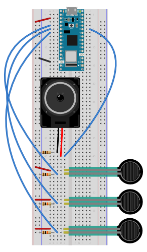
Here’s an example of how to use the note constants to make a simple keyboard. Figures 18-20 show the circuit. Note that this can be modified to use fewer force sensing resistors if you haven’t got three of them. Or more if you have lots of them!
Figure 18. Schematic view of an Arduino connected to three force sensing resistors and a speaker. Delete one fixed resistor-FSR pair if you have only two FSRs.
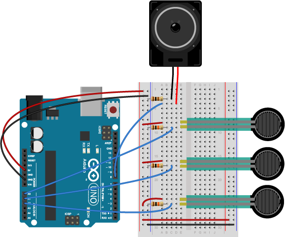
Figure 19. Breadboard view of an Arduino connected to three force sensing resistors (FSR) and a speaker. Each of the three FSRs have one of their respective legs connected to +5 volts. Each of the other legs connect to one leg of a 10-kilohm resistor and simultaneously connect to one of the Arduino’s analog input pins. In this case the pin connections are A0, A1, and A2. Each of the respective 10-kilohm resistors then connect to ground. The red positive wire of the speaker is connected to digital pin 8 of the Arduino. The black ground wire of the speaker is connected to one leg of a 100 ohm resistor. The other leg of the 100 ohm resistor then connects to ground. Delete one fixed resistor-FSR pair if you have only two FSRs.
Figure 20. Breadboard view of an Arduino Nano connected to three force sensing resistors (FSR) and a speaker. Each of the three FSRs have one of their respective legs connected to the voltage bus of the breadboard. Each of the other legs connect to one leg of a 10-kilohm resistor and simultaneously connect to one of the Arduino’s analog input pins. In this case the pin connections are A0, A1, and A2. Each of the respective 10-kilohm resistors then connect to ground. The red positive wire of the speaker is connected to digital pin 8 of the Arduino. The black ground wire of the speaker is connected to one leg of a 100 ohm resistor. The other leg of the 100 ohm resistor then connects to ground.
Program it
Make a sketch that plays a note on each sensor when the sensor is above a given threshold.
Start with a few constants: one for the threshold, one for the speaker pin number, and one for the duration of each tone. To make this instrument work, you need to know what note corresponds to each sensor. Include pitches.h as you did above, then make an array that contains three notes, A4, B4, and C3 as well. Set all of this up at the beginning of your sketch, before setup().
#include "pitches.h"

const int threshold = 10;      // minimum reading of the sensors that generates a note
const int speakerPin = 8;      // pin number for the speaker
const int noteDuration = 20;   // play notes for 20 ms

// notes to play, corresponding to the 3 sensors:
int notes[] = {
NOTE_A4, NOTE_B4,NOTE_C4 };
You don’t need anything in your setup(), but in your loop, you need a for loop that iterates over the first three analog inputs, 0, 1, and 2. For each one, read the sensor, and if it’s above a threshold, play the corresponding note in the notes array for the note duration.
#include "pitches.h"

const int threshold = 10;      // minimum reading of the sensors that generates a note
const int speakerPin = 8;      // pin number for the speaker
const int noteDuration = 20;   // play notes for 20 ms

// notes to play, corresponding to the 3 sensors:
int notes[] = {
NOTE_A4, NOTE_B4,NOTE_C4 };

void setup() {

}

void loop() {
  for (int thisSensor = 0; thisSensor < 3; thisSensor++) {
    // get a sensor reading:
    int sensorReading = analogRead(thisSensor);

    // if the sensor is pressed hard enough:
    if (sensorReading > threshold) {
      // play the note corresponding to this sensor:
      tone(speakerPin, notes[thisSensor], noteDuration);
      // delay as long as the note is playing:
      delay(noteDuration);
    }
  }
}
When you upload this sketch, you should have a three-key keyboard.
Get Creative
Now that you’ve got the basics, think about making an instrument for one of your projects. For more background on musical structure, see these notes on tone and generating a melody.
Doing More with Sound Output
If you’re interested going deeper into using sound outputs using speakers, take a look at the Mozzi Libary to produce more complex sound. In a future session, you’ll learn to play and control .wav files from Arduino, which is based on the I2S Library that connect digital audio devices together.
This is an introduction to basic analog output on a microcontroller. In order to get the most out of it, you should know something about the following concepts. You can check how to do so in the links below:
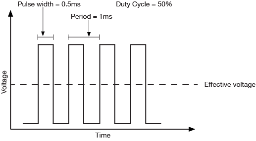
Just as with input, there are times when you want greater control over a microcontroller’s output than a digital output affords. You might want to control the brightness of a lamp, for example, or the turn of a pointer on a dial, or the speed of a motor. In these cases, you need an analog output. The most likely things that you might want to vary directly from a microcontroller are lights, sound devices, or things controlled by motors. For many of these, there will be some other controller in between your microcontroller and the final output device. There are lighting dimmers, motor controllers, and so forth, most of which can be controlled using some form of serial digital communication. What’s covered here are simple electrical devices that can be controlled by a changing voltage. The Arduino and other digital microcontrollers generally can’t produce a varying voltage, they can only produce a high voltage or low voltage. Instead, you “fake” an analog voltage by producing a series of voltage pulses at regular intervals, and varying the width of the pulses. This is calledpulse width modulation (PWM). The resulting average voltage is sometimes called a pseudo-analog voltage. The graph in Figure 1 shows how PWM works. You pulse the pin high for the same length of time that you pulse it low. The time the pin is high (called the pulsewidth) is about half the total time it takes to go from low to high to low again. This ratio is called the dutycycle and the total time from off through on to off again is the period. The duty cycle in this case 50%, and the effective voltage is half the total voltage.
Figure 1. PWM with a 50% duty cycle has an effective voltage of 50% of the maximum output voltage. Over time, the voltage is on half the time and off half the time.
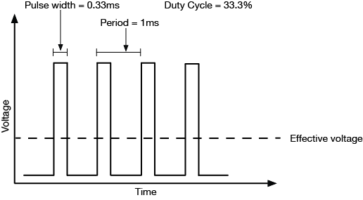
If you make the duty cycle less than 50% by pulsing for a shorter amount of time than you pause, you get a lower effective voltage as shown in Figure 2:
Figure 2. Graph of pulse-width-modulation (PWM) with a 33% duty cycle. Effective voltage is a third of the maximum voltage. Over time, the voltage is on one third the time and off two thirds of the time.
The period is usually a very small time, on the order of a few microseconds or milliseconds at most. The Arduino boards have a few pins which can generate a continuous PWM signal. On the Arduino Nano 33 IoT. they’re pins 2, 3, 5, 6, 9, 10, 11, 12, A2, A3, and A5. On the Arduino Uno, they’re pins 3, 5, 6, 9, 10, and 11. To control them, you use the analogWrite() command like so:
analogWrite(pin, duty);
pin refers to the pin you’re going to pulse
duty is a value from 0 – 255. 0 corresponds to 0 volts, and 255 corresponds to 5 volts. Every change of one point changes the pseudo-analog output voltage by 5/255, or 0.0196 volts.
Applications of Pulse Width Modulation
LED dimming
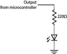
The simplest application of analogWrite() is to change the brightness of an LED. Connect the LED as you did for a digital output, as shown in Figure 3, then use analogWrite() to change its brightness. You’ll notice that it doesn’t change on a linear scale, however.
Figure 3. You can dim an LED with the same circuit as you used for digital output. Just use analogWrite() on the pin to which the LED is connected.
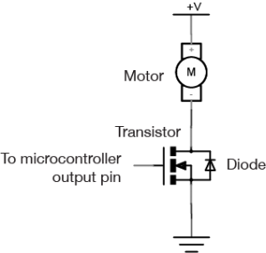
DC Motor Speed Control
You can vary the speed of a DC motor using the analogWrite() command as well. The schematic is in Figure 4. You use the same transistor circuit as you would to turn on and off the motor, shown in Figure 4, but instead of setting the output pin of the microcontroller high or low, you use the analogWrite() on it. The transistor turns on and off at a rate faster than the motor can stop and start, so the result is that the motor appears to smoothly speed up and slow down.
For more on DC motor control, see the following links:
Figure 4. Schematic of motor control with an Arduino, using a MOSFET. One terminal of the motor is connected to a high-current power supply and the other is connected to the MOSFET’s drain pin. The MOSFET’s source pin is connected to ground and its gate is connected to a microcontroller output pin. A protection diode’s cathode is attached to the source of the MOSFET, and the anode is connected to the drain.
Note: Filter circuits
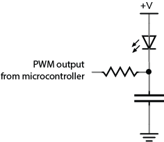
Filter circuits are circuits which allow voltage changes of only a certain frequency range to pass. For example, a low-pass filter would block frequencies above a certain range. This means that if the voltage is changing more than a certain number of times per second, these changes would not make it past the filter, and only an average voltage would be seen. Imagine, for example, that your PWM is operating at 1000 cycles per second, or 1000 Hertz (Hz). If you had a filter circuit that blocked frequencies above 1000 Hz, you would see only an average voltage on the other side of the filter, instead of the pulses. A basic low-pass filter consists of a resistor and a capacitor, connected as shown in Figure 5:
Figure 5. Schematic: A basic low-pass filter. An LED’s anode is connected to voltage and its cathode is attached to one terminal of a capacitor. The capacitor’s other terminal is connected to ground. A resistor connects to the junction where the the LED and the capacitor meet. The other end of the resistor is connected to a microcontroller’s output pin.
The relationship between frequency blocked and the values of the capacitor and resistor is as follows:
frequency = 1/ (2π *resistance * capacitance)
A 1.5-kilohm resistor and a 0.1-microfarad capacitor will cut off frequencies above around 1061 Hz. If you’re interested in filters, experiment with different values from there to see what works best.
Servomotors
Perhaps the most exciting thing you can do as analog output is to control the movement of something. One simple way to do this is to use a servomotor. Servomotors are motors with a combination of gears and an embedded potentiometer (variable resistor) that allows you to set their position fairly precisely within a 180-degree range. They’re very common in toys and other small mechanical devices. They have three wires:
power (usually +5V)
ground
control
Connect the +5V directly to a 5V power source (the Arduino’s 5V or 3.3V output will work for one servo, but not for multiple servos). Ground it to the same ground as the microcontroller. Attach the control pin to any output pin on the microcontroller. Then you need to send a series of pulses to the control pin to set the angle. The longer the pulse, the greater the angle.
To pulse the servo, you generally give it a 5-volt, positive pulse between 1 and 2 milliseconds (ms) long, repeated about 50 times per second (i.e. 20 milliseconds between pulses). The width of the pulse determines the position of the servo. Since servos’ travel can vary, there isn’t a definite correspondence between a given pulse width and a particular servo angle, but most servos will move to the center of their travel when receiving 1.5-ms pulses. This is a special case of pulse width modulation, in that you’re modifying the pulse, but the period remains fixed at 20 milliseconds. You could write your own program to do this, but Arduino has a library for controlling servos. See the Servo lab for more on this.
Pulse width modulation can generate a pseudo-analog voltage for dimming and motor control, but can you use it to generate pitches on a speaker? Remember that you’re changing the duty cycle but not the period of the signal, so the frequency doesn’t change. If you were to connect a speaker to a pin that’s generating a PWM signal, you’d hear one steady pitch.
If you want to generate a changing tone on an Arduino microcontroller, however, there is a tone() command that will do this for you:
tone(pin, frequency);
This command turns the selected pin on and off at a frequency that you set. With this command, you can generate tones reasonably well. For more on this, see the Tone Output lab.
As a summary, Table 1 below shows the ranges of values for digital input/output and analog input/output, which have been discussed in Digital Input & Output, Analog Input, and this page.
Digital
Input
(Digital Pins)
0 [LOW] or 1 [HIGH] (2^0)
0V or 3.3V (newer microcontrollers)
0V or 5V (older microcontrollers)
Output
(Digital Pins)
0 [LOW] or 1 [HIGH] (2^0)
0V or 3.3V (newer microcontrollers)
0V or 5V (older microcontrollers)
Analog
Input
(Analog Input Pins)
0 ~ 1023 (<210)
3.3 / 210
Output
(Digital PWM Pins)
0 ~ 255 (<28)
3.3 / 28
Table 1. The Ranges of Values for Digital/Analog Input/Output