Analog Output

Introduction

This is an introduction to basic analog output on a microcontroller. In order to get the most out of it, you should know something about the following concepts.  You can check how to do so in the links below:

The following video links will help in understanding analog output:

Analog Output

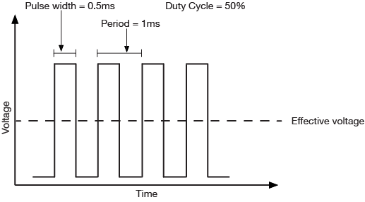
Just as with input, there are times when you want greater control over  a microcontroller’s output than a digital output affords. You might want to control the brightness of a lamp, for example, or the turn of a pointer on a dial, or the speed of a motor. In these cases, you need  an analog output. The most likely things that you might want to vary directly from a microcontroller are lights, sound devices, or things controlled by motors. For many of these, there will be some other controller in between your microcontroller and the final output device. There are lighting dimmers, motor controllers, and so forth, most of which can be controlled using some form of serial digital communication. What’s covered here are simple electrical devices that can be controlled by a changing voltage. The Arduino and other digital microcontrollers generally can’t produce a varying voltage, they can only produce a high voltage or low voltage. Instead, you “fake” an analog voltage by producing a series of voltage pulses at regular intervals, and varying the width of the pulses. This is called pulse width modulation (PWM). The resulting average voltage is sometimes called a pseudo-analog voltage. The graph in Figure 1 shows how PWM works. You pulse the pin high for the same length of time that you pulse it low. The time the pin is high (called the pulsewidth) is about half the total time it takes to go from low to high to low again. This ratio is called the duty cycle and the total time from off through on to off again is the period. The duty cycle in this case 50%, and the effective voltage is half the total voltage.

Related video: Pseudo-Analog Explained

Graph of pulse-width-modulation (PWM) with a 50% duty cycle
Figure 1. PWM with a 50% duty cycle has an effective voltage of 50% of the maximum output voltage. Over time, the voltage is on half the time and off half the time.

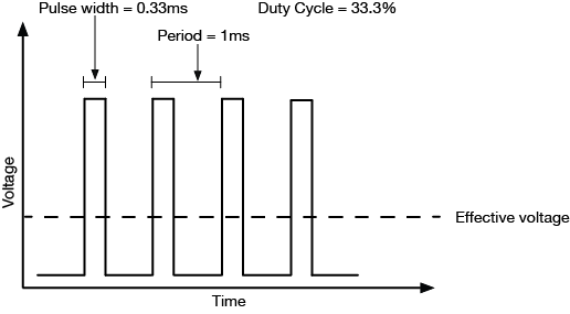
If you make the duty cycle less than 50% by pulsing for a shorter amount of time than you pause, you get a lower effective voltage as shown in Figure 2:

Graph of pulse-width-modulation (PWM) with a 33% duty cycle. Effective voltage is a third of the maximum voltage
Figure 2. Graph of pulse-width-modulation (PWM) with a 33% duty cycle. Effective voltage is a third of the maximum voltage. Over time, the voltage is on one third the time and off two thirds of the time.

Related video: PWM graphed and see it on the scope

The period is usually a very small time, on the order of a few microseconds or milliseconds at most. The Arduino boards have a few pins which can generate a continuous PWM signal. On the Arduino Nano 33 IoT. they’re pins 2, 3, 5, 6, 9, 10, 11, 12, A2, A3, and A5. On the Arduino Uno, they’re pins 3, 5, 6, 9, 10, and 11. To control them, you use the analogWrite() command like so:

analogWrite(pin, duty);
  • pin refers to the pin you’re going to pulse
  • duty is a value from 0 – 255. 0 corresponds to 0 volts, and 255 corresponds to 5 volts. Every change of one point changes the pseudo-analog output voltage by 5/255, or  0.0196 volts.

Applications of Pulse Width Modulation

LED dimming

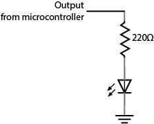
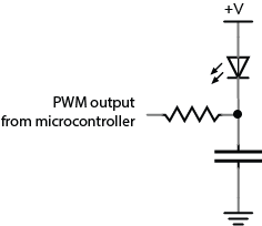
The simplest application of analogWrite() is to change the brightness of an LED. Connect the LED as you did for a digital output, as shown in Figure 3, then use analogWrite() to change its brightness. You’ll notice that it doesn’t change on a linear scale, however.

Related video: See the effect of PWM on the LED

Digital output schematic. A 220-ohm resistor is connected to an output from a microcontroller. The other end of the resistor is connected in series with the anode of an LED. The cathode of the LED is connected to ground.
Figure 3. You can dim an LED with the same circuit as you used for digital output. Just use analogWrite() on the pin to which the LED is connected.

DC Motor Speed Control

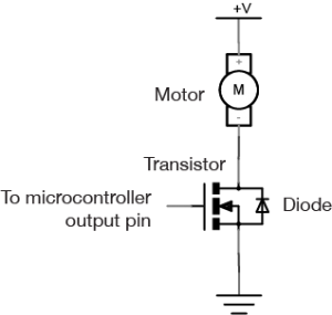
You can vary the speed of a DC motor using the analogWrite() command as well. The schematic is in Figure 4. You use the same transistor circuit as you would to turn on and off the motor, shown in Figure 4, but instead of setting the output pin of the microcontroller high or low, you use the analogWrite() on it. The transistor turns on and off at a rate faster than the motor can stop and start, so the result is that the motor appears to smoothly speed up and slow down.

For more on DC motor control, see the following links:

Schematic of motor control with an Arduino, using a MOSFET. One terminal of the motor is connected to +5 volts. The other side is connected to the source pin of a MOSFET transistor. The gate of the transistor is connected to a microcontroller's output pin. The drain pin of the MOSFEt is connected to ground. There is a diode connected in parallel with the transistor. its anode is connected to the drain, and its cathode is connected to the source.
Figure 4. Schematic of motor control with an Arduino, using a MOSFET. One terminal of the motor is connected to a high-current power supply and the other is connected to the MOSFET’s drain pin. The MOSFET’s source pin is connected to ground and its gate is connected to a microcontroller output pin. A protection diode’s cathode is attached to the source of the MOSFET, and the anode is connected to the drain.
Note: Filter circuits

Filter circuits are circuits which allow voltage changes of only a certain frequency range to pass. For example, a low-pass filter would block frequencies above a certain range. This means that if the voltage is changing more than a certain number of times per second, these changes would not make it past the filter, and only an average voltage would be seen. Imagine, for example, that your PWM is operating at 1000 cycles per second, or 1000 Hertz (Hz).  If you had a filter circuit that blocked frequencies above 1000 Hz, you would see only an average voltage on the other side of the filter, instead of the pulses. A basic low-pass filter consists of a resistor and a capacitor, connected as shown in Figure 5:

Schematic drawing of a low-pass filter for an LED. The LED's anode is connected to +5 volts. Its cathode connects to a resistor. The resistor's other end connects to the PWM output of a microcontroller. The junction where the cathode of the LED and the resistor meet is also connected to a capacitor. The other terminal of the capacitor is connected to ground.
Figure 5. Schematic: A basic low-pass filter. An LED’s anode is connected to voltage and its cathode is attached to one terminal of a capacitor. The capacitor’s other terminal is connected to ground. A resistor connects to the junction where the the LED and the capacitor meet. The other end of the resistor is connected to a microcontroller’s output pin.

The relationship between frequency blocked and the values of the capacitor and resistor is as follows:

frequency = 1/ (2π *resistance * capacitance)

A 1.5-kilohm resistor and a 0.1-microfarad capacitor will cut off frequencies above around 1061 Hz. If you’re interested in filters, experiment with different values from there to see what works best.

Servomotors

Perhaps the most exciting thing you can do as analog output is to control the movement of something. One simple way to do this is to use a servomotor. Servomotors are motors with a combination of gears and an embedded potentiometer (variable resistor) that allows you to set their position fairly precisely within a 180-degree range. They’re very common in toys and other small mechanical devices. They have three wires:

  • power (usually +5V)
  • ground
  • control

Connect the +5V directly to a 5V power source (the Arduino’s 5V or 3.3V output will work for one servo, but not for multiple servos). Ground it to the same ground as the microcontroller. Attach the control pin to any output pin on the microcontroller. Then you need to send a series of pulses to the control pin to set the angle. The longer the pulse, the greater the angle.

To pulse the servo, you generally give it a 5-volt, positive pulse between 1 and 2 milliseconds (ms) long, repeated about 50 times per second (i.e. 20 milliseconds between pulses). The width of the pulse determines the position of the servo. Since servos’ travel can vary, there isn’t a definite correspondence between a given pulse width and a particular servo angle, but most servos will move to the center of their travel when receiving 1.5-ms pulses. This is a special case of pulse width modulation, in that you’re modifying the pulse, but the period remains fixed at 20 milliseconds. You could write your own program to do this, but Arduino has a library for controlling servos. See the Servo lab for more on this.

Related video: Analog Output – Servo

Changing Frequency

Pulse width modulation can generate a pseudo-analog voltage for dimming and motor control, but can you use it to generate pitches on a speaker? Remember that you’re changing the duty cycle but not the period of the signal, so the frequency doesn’t change. If you were to connect a speaker to a pin that’s generating a PWM signal, you’d hear one steady pitch.

If you want to generate a changing tone on an Arduino microcontroller, however, there is a tone() command that will do this for you:

tone(pin, frequency);

This command turns the selected pin on and off at a frequency that you set. With this command, you can generate tones reasonably well. For more on this, see the Tone Output lab.

Related video: Analog Output – Tone

Ranges of Values

As a summary, Table 1 below shows the ranges of values for digital input/output and analog input/output, which have been discussed in Digital Input & Output, Analog Input, and this page.

DigitalInput (Digital Pins)0 [LOW] or 1 [HIGH] (2^0) 0V or 3.3V (newer microcontrollers) 0V or 5V (older microcontrollers)
Output (Digital Pins)0 [LOW] or 1 [HIGH] (2^0) 0V or 3.3V (newer microcontrollers) 0V or 5V (older microcontrollers)
AnalogInput (Analog Input Pins)0 ~ 1023 (<210)3.3 / 210
Output (Digital PWM Pins)0 ~ 255 (<28)3.3 / 28
Table 1. The Ranges of Values for Digital/Analog Input/Output


Analog Input

Introduction

This is an introduction to basic analog input on a microcontroller. In order to get the most out of it, you should know something about the following concepts.  You can check how to do so in the links below:

These video links will help in understanding analog input:

Analog Input

While a digital input to a microcontroller can tell you about discrete changes in the physical world, such as whether the cat is on the mat, or the cat is off the mat, there are times when this is not enough. Sometimes you want to know how fat the cat on the mat is. In order to know this, you’d need to be able to measure the force the cat exerts on the mat as a variable quantity. When you want to measure variably changing conditions like this, you need analog inputs. An analog input to a microcontroller is an input that can read a variable voltage, typically from 0 volts to the maximum voltage that powers the microcontroller itself.

Many transducers are available to convert various changing conditions to changing electrical quantities. There are photocells that convert the amount of light falling on them to a varying resistance; flex sensors that change resistance as they are bent; Force-sensitive resistors (FSRs) that change resistance based on a changing force applied to the surface of the sensor; thermistors that change resistance in response to changing heat; and many more.

Related video: Resistors, variable resistors, and photocells

In order to read these changing resistances, you put them in a circuit and pass a current through them, so that you can see the changing voltage that results. There are a few variations on this circuit. The simplest is called a voltage divider. Because the two resistors are in series voltage at the input to the microcontroller is proportional to the ratio of the resistors. If they are equal, then the input voltage is half the total voltage. So in the circuit in Figure 1, if the variable resistor changes (for example, if it’s a flex sensor being bent), then the voltage at the input changes.  The fixed resistor’s value is generally chosen to complement the variable resistor’s range. For example, if you have a variable resistor that’s 10-20 kilohms, you might choose a 10 kilohm fixed resistor.

analog in schematic
Figure 1. voltage divider with a variable resistor and a fixed resistor

In Figure 2, you use a potentiometer,  which is a variable resistor with three connections. The center of the potentiometer, called the wiper,  is connected to the microcontroller. The other two sides are attached to power and ground. The wiper can move from one end of the resistor to the other. In effect, it divides the resistor into two resistors and measures the resistance at the point where they meet, just like a voltage divider.

Related videos:

potentiometer schematic
Figure 2. potentiometer schematic

Since a microcontroller’s inputs can read only two values (typically 0 volts or the controller’s supply voltage), an analog input pin needs an extra component to read this changing, or analog voltage, and convert it to a digital form. An analog-to-digital converter (ADC) is a device that does this. It reads a changing input voltage and converts it to a binary value, which a microcontroller can then store in memory.Many microcontrollers have ADCs built in to them. Arduino boards have an ADC attached to the analog input pins.

The ADC in the Arduino can read the input voltage at a resolution of 10 bits. That’s a range of 1024 points. If the input voltage range (for example, on the Uno) is 0 to 5 volts, that means that the smallest change it can read is 5/1024, or 0.0048 Volts. For a 3.3V board like the Nano 33 IoT, it’s 0.0029 volts. When you take a reading with the ADC using the analogRead() command, the microcontroller stores the result in memory. It takes an int type variable to store this, because a byte is not big enough to store the 10 bits of an ADC reading. A byte can hold only 8 bits, or a range from 0 to 255.

The command in Arduino is the analogRead() command, and it looks like this:

sensorReading = analogRead(pin);
  • Pin is the analog input pin you are using;
  • sensorReading is an integer variable containing the result from the ADC.

The number produced in sensorReading is will be between 0 and 1023. Its maximum may be less, depending on the circuit you use. A potentiometer will give the full range, but a voltage divider for a variable resistor like a force sensing resistor or flex sensor, where one of the resistors is fixed, will not.

The analog inputs on an Arduino (and in fact, on most microcontrollers), are all connected to the same ADC circuit, so when the microcontroller has to switch the ADC’s input from one pin to another when you try to read two pins one after another. If you read them too fast, you can get unstable readings. You can also get more reliable readings by introducing a small delay after you take an analog reading. This allows the ADC time to stabilize before you take your next reading.

Here’s an example of how to read three analog inputs with minimal delay and maximum stability:

 sensorOne = analogRead(A0);
 delay(1);
 sensorTwo = analogRead(A1);
 delay(1);
 sensorOne = analogRead(A2);
 delay(1);

Analog and digital inputs are the two simplest ways that a microcontroller reads changing sensor voltage inputs. Once you’ve understood these two, you’re ready to use a variety of sensors.

Electricity: the Basics

Introduction

Adapted from Understanding Electricity
In order to understand how electronic circuits work, and how to use them to build physical interfaces to digital systems using microcontrollers, there are some basic terms, relationships, and components that you need to know about. What follows is a brief introduction to those terms.

You won’t need to know anything about electricity or electronics to understand this page.

Definitions

Electricity is the flow of electrical energy through conductive materials.  An electrical circuit is made up of two elements: a power source and components that convert the electrical energy into other forms of energy.  We build electrical circuits to do work, or to sense activity in the physical world.

Sensors are components that convert other forms of energy into electrical energy so we can read the changes in those other forms. Switches, knobs, light and motion sensors all fit in this category.  Actuators are components that convert electrical energy into other forms. Light bulbs, motors, LEDs, and heaters are all actuators.

Electronics refers to reading changes in electrical properties as information.  For example, a microphone changes sound pressure waves in the air to a changing electrical voltage. This process of changing one energy into another is called transduction, and devices that do it are called transducers. Much of the technical work of physical computing is about figuring out what forms of energy a person is generating, and what kind of transducer you can buy or build to read that energy. In order to do that, though, it’s necessary to understand a few things about electricity. Following are a few terms we’ll use to refer to electrical properties and components. After that, we’ll talk about the important relationships between some of these terms.

Voltage is a measure of the difference in electrical potential energy between two points in a circuit. It is measured in Volts.

Current is a measure of the magnitude of the flow of electrons through a particular point in a circuit. It is measured in Amperes, or Amps.

Resistance is a measure of a material’s ability to oppose the flow of electricity. It is measured in Ohms.

To understand the relationship between voltage, current, and resistance, imagine an avalanche of snow on a mountain. The height of the mountain is analogous to the voltage; the higher the mountain, the more potential energy the falling material has.  The amount of snow and rocks in the avalanche is analogous to the current.  And the steepness of the mountain is analogous to the resistance: the steeper the mountain, the less it will resist the flow of the snow and rocks. We’ll define this a bit more formally below.

Every circuit has to have a source of electrical energy and a load that uses the energy.All of the electrical energy in a circuit has to get used by the load. The load will convert the electrical energy to some other form of energy, A circuit with no load  is called a short circuit. In a short circuit, the power source feeds all of its power through the wires and back to itself, and either the wires melt (if you’re lucky), or the battery and the components blow up.

Figure 1 is a very basic circuit, consisting of a lamp, a pushbutton, and a battery. The battery is the source and the lamp is the load. The electrical energy coming from the battery is converted to heat and light energy by the light bulb. All of the energy is used up in the process. However, if the bulb cannot take the voltage produced by the battery (for example, a 6V lamp and a 9V battery), the lamp’s filament will melt trying to transduce all the electrical energy into light and heat.

One AA Battery connected to a button switch and lamp in series
Figure 1. AA Battery connected to a button switch and lamp in series

There are two common kinds of circuits:  Direct Current (DC), and Alternating Current (AC). In a DC circuit, current always flows one direction. In an AC circuit, the direction of current flow is reversed in a regular repeating cycle.  Most of the circuits we’ll talk about in this class will be DC circuits.

Schematic diagrams are diagrams of circuits that represent the electrical relationships between the components in the circuit. A schematic doesn’t  always show the spatial arrangement of the components; it’s arranged so that you can best understand the flow of the electricity. You can find a large collections of schematic symbols in SVG format, useful for drawing your own, on the Wikipedia page for “Electronic Symbol”. An SVG collection of them in one file, convenient for editing into your own diagrams, can be found on this Wikimedia commons page. The symbols for the components you’ll use most commonly in this class are shown below as well.

Figure 2 show two schematics of the light bulb circuit above. In both, the important parts to note are the functional components, namely the lamp and the switch, and the power and ground terminals. In the diagram on the right, the whole circuit is shown as a loop, with the battery (marked V1) to the left of the loop. In the diagram on the left, the circuit is not shown as a loop. Instead, the power source is at the top, and the point of lowest energy, or ground, is at the bottom.  This diagram shows the flow of energy from the top of the diagram to the bottom. Related Video: Intro to Schematics

Schematic of a 1.5 volt battery connected to a switch and lamp in series. In the diagram on the right, the whole circuit is shown as a loop, with the battery (marked V1) to the left of the loop. In the diagram on the left, the circuit is not shown as a loop. Instead, the power source is at the top, and the point of lowest energy, or ground, is at the bottom.
Figure 2. Two schematics of a 1.5 volt battery connected to a switch and lamp in series.

Components

Conductors are materials through which electrical current moves freely.

Insulators are materials which prevent the flow of electricity.

Resistors resist, but do not totally block, the flow of electricity. They are used to control the flow of current. Current can move either way through a resistor, so it doesn’t matter which way they’re connected in a circuit. Resistors are measured by their resistance in ohms (Ω), often seen in kilohms (kΩ). They are symbolized as shown in Figure 3:

Four resistor types, from left to right: Fixed Value Resistor, Variable Resistor, Potentiometer, Photo-resistor or light dependent resistor
Figure 3. Four resistor types, from left to right: Fixed Value Resistor, Variable Resistor, Potentiometer, Photo-resistor or light dependent resistor.

Related videos: Resistors, variable resistors, and photocells; Potentiometer

There are many different types of variable resistors, including:

  • Thermistors change resistance in reaction to varying temperature;
  • Photoresistors change resistance in reaction to varying light;
  • Flex sensors change resistance in reaction to being bent or flexed;
  • Force sensing resistors change resistance in reaction to a force placed upon them;

Capacitors store up electricity while current is flowing into them, then release the energy when the incoming current is removed. Capacitors are measured by their capacitance in farads (F), most commonly seen in microfarads (µF). Sometimes they are polarized, meaning current can only flow through them in a specific direction, and sometimes they are not. If a capacitor is polarized, it will be marked as such on the diagram. Don’t wire a polarized capacitor backwards; this can damage the capacitor, and your circuit. Capacitors are also rated by their maximum voltage. Don’t apply more voltage to a capacitor than it’s rated for, or it will explode.

Capacitors are symbolized as shown in Figure 4:

Schematic symbols of a polarized capacitor and a non-polarized capacitor. Polarized shows a + symbol near the anode and the cathode is connected to a curved line. The non polarized capacitor symbol contains only straight lines and is symmetric
Figure 4. Schematic symbols of a polarized capacitor and a non-polarized capacitor

Related video: Capacitors

Diodes permit the flow of electricity in one direction, and block it in the other direction. Because of this, they can only be placed in a circuit in one direction. Light-Emitting Diodes (LED’s) are special types of diodes which emit light when current flows through them.  Diodes are symbolized as shown in Figure 5:

Schematic symbols of a diode and a light-emitting diode. The light-emitting diode looks like the diode symbol with 2 arrows pointing away from the center of the symbol.
Figure 5. Schematic symbols of a diode and a light-emitting diode (LED)

Related video: Diodes and LEDs

Switches and pushbuttons control the flow of current through a junction in a circuit, as shown in Figure 6:

Drawing of a switch, left, and a pushbutton, right. The switch has two lines separated by a gap, with a hinged third line almost connecting them, indicating that it is the switch between the two contacts. The pushbutton has two lines separated by a gap and a third line parallel to them, indicating that, it would close the connection between the first two lines when pressed against them.
Figure 6. Schematic drawing of a switch and a pushbutton

Related video: Switches

Transistors and relays are electrical switching devices, as shown in Figure 7:

Schematic symbols for an NPN transistor, a PNP Transistor, and a Relay
Figure 7. Schematic symbols for an NPN transistor, a PNP Transistor, and a Relay

Related video: Relays

Piezoelectric devices create a varying voltage in reaction to slight changes in pressure.

Relationships

Voltage (V), Current (I), and Resistance (R) are all related, by the following formula, as shown in figure 8:

Volts = Amps x Ohms

or

V = I x R

Three equations using ohms law to calculate Voltage, Amperage, or Resistance. A circle is divided into 3 sections, each section containing one element of Ohms law, V for voltage, I for Amperage, R for resistance. Each equation is adjacent to the corresponding section of the circle
Figure 8. Three equations using ohms law to calculate Voltage, Amperage, or Resistance

Related video: Ohm’s Law Part 1 & Part 2. See also Measuring Voltage and Current.

Current (I), voltage (V), and resistance (R) are also related to electrical power (P) (measured in watts), as follows:

Watts = Volts * Amps

or

P = V * I

Electrical current flows from places of higher potential energy to places of lower potential energy (i.e. from positive to negative), as shown in Figure 9. In order for current to flow, there has to be a circuit, and there has to be a load to convert the electrical energy into some other form of energy.

Simple circuit showing the direction of current flowing from the + V terminal to ground
Figure 9. Simple circuit showing the direction of current flowing from the + V terminal to ground

Ground is the place in a circuit with where the potential energy of the electrons is zero. Sometimes this point is connected to the actual ground, either through a grounded electrical circuit, water pipe, or some other method. Basically, any conductor that goes to the earth will do.

Electrical Energy Flow in a Circuit

When you start to add multiple components to a circuit, following the electrical energy can get a bit more complex.  Following are some principles that explain how energy flows in a circuit.

Electrical components can be arranged in a circuit so that the energy flows through one to the other, or they can be arranged so that the energy is split, flowing through both at the same time. When the energy flows from one to the other, the components are in series (Figure 10). When it flows through them at the same time, they are in parallel (Figure 11).

Two lightbulbs in series
Figure 10. Two lightbulbs in series
Two lightbulbs wired in parallel
Figure 11. Two lightbulbs wired in parallel

There are a few rules that explain how electrical energy moves through these circuits:

Current tends to follow the path of least resistance to the ground. So if it has a choice of two paths in a circuit, and one has less resistance, that’s the path it’ll take. Looking at the parallel circuit above, if one light bulb offered less resistance, then more of the current wold pass through that bulb.

In any given circuit, the total voltage around the path of the circuit is zero. Each component that offers a resistance lowers the voltage, and by the time you reach the end of the circuit loop, there will be no voltage left. In other words, all energy generated by the electrical power source in a circuit is converted to some other form of energy.  Looking at the light bulbs in series above, if you were to measure the voltage on between the two contacts of each bulb, it would be less than the voltage between the contacts of the battery, but when you add up the voltages for all the bulbs, the sum would equal the voltage of the battery.

This explains why some components in a circuit get warm when you don’t expect them to. They are offering resistance to the energy in the circuit, and if they are not efficient at converting that energy into their desired form of energy, they convert it to heat.

The amount of current going into any point in a circuit is the same as the amount coming out of that point.

Let’s look in more detail at how the current and voltage changes when components are in series or in parallel:

When two components are in series, they are placed one after another, as shown in Figure 12:

Two resistors wired in series with a junction in between the resistors
Figure 12. Two resistors wired in series.

When resistors are in series, the voltage drops across each resistor, and the total resistance is equal to the sum of all the resistors:

Resistors in series:

Rtotal = R1 + R2 + R3

In the above circuit, the current through both of the resistors is the same and the voltage drops across each resistor, and the total of all the voltage drops equals the voltage across the battery. The voltage between the junction point and the negative terminal of the battery (which is the ground of this circuit)  is dependent on the ratio of the two resistors in series. If the resistors are equal in resistance value, then the voltage at the junction point is exactly half that of the battery’s total voltage.

When two components are in parallel, they are placed beside each other, as shown in Figure 13:

Two resistors wired in parallel
Figure 13. Two resistors wired in parallel

For resistors in parallel, the voltage across them is equal, but the current is divided between them. The divided current across the parallel resistors is equal to the total current. So I1 + I2 = Itotal. That means that

1/Rtotal = 1/R1 + 1/R2 + 1/R3

If the resistors are equal in resistance value, then the current flowing through each of them is half that of the total current.

Though it’s sometimes useful to think about the mathematical relationships of parallel and series circuits, it’s often more useful to think about them in terms of practical effects: resistors divide voltage when in series, and divide amperage when in parallel.

When you’re ready to begin building circuits, read the Breadboard Setup Lab for a quick introduction to how to use a solderless breadboard. The Components Lab introduces many of the components you will use and the Electronics lab introduces you to how to measure electrical properties. You should also read the the switches lab, and watch this video about connections in schematics.

Digital Input & Output

Introduction

This is an introduction to basic digital input and output on a microcontroller. In order to get the most out of it, you should know something about the following concepts.  You can check how to do so in the links below:

These videos will help in understanding digital inputs and outputs:

Digital Inputs

When you’re trying to sense activity in the physical world using a microcontroller, the simplest activities you can sense are those in which you only need to know one thing about the physical world: Whether something is true or false. Is the viewer in the room or out? Are they touching the table or not? Is the door open or closed? In these cases, you can determine what you need to know using a digital input, or switch.

Digital or binary inputs to microcontrollers have two states: off and on. If voltage is flowing, the circuit is on. If it’s not flowing, the circuit is off. To make a digital circuit, you need a circuit, and a movable conductor which can either complete the circuit, or not.

Schematic of a Digital Input to a microcontroller
Figure 1. Schematic of a Digital Input to a microcontroller

Figure 1 shows the electrical schematic for a digital input to a microcontroller. The current has two directions it can go to ground: through the resistor or through the microcontroller. When the switch is closed, the current will follow the path of least resistance, to the microcontroller pin, and the microcontroller can then read the voltage. The microcontroller pin will then read as high voltage or HIGH. When the switch is open, the resistor connects the digital input to ground, so that it reads as zero voltage, or LOW.

On an Arduino module, you declare the pin to be an input at the top of your program. Then you read it for the values 1 (HIGH) or 0 (LOW), like so:

void setup() {
 // declare pin 2 to be an input:
 pinMode(2, INPUT);
 declare pin 3 to be an output:
 pinMode(3, OUTPUT);
}

void loop() {
 // read pin 2:
 if (digitalRead(2) == 1) {
   // if pin 2 is HIGH, set pin 3 HIGH:
   digitalWrite(3, HIGH);
 } else {
   // if pin 2 is LOW, set pin 3 LOW:
   digitalWrite(3, LOW);
}

Digital output

Just as digital inputs allow you to sense activities which have two states, digital or binary outputs allow you to control activities which can have two states. With a digital output you can either turn something off or on. Figure 2 is the schematic diagram for digital output controlling an LED:

Schematic of and led as a digital output from a microcontroller
Figure 2. Schematic of and led as a digital output from a microcontroller

Digital outputs are often used to control other electrical devices besides LEDs,  through transistors or relays. For more information on that, see these notes on controlling high-current circuits.

On an Arduino module, you declare the pin an output at the top of the program just like you did with inputs. Then in the body of the program you use the digitalWrite() command with the values HIGH and LOW to set the pin high or low, as you’ve seen above.
Here’s a simple blinking LED program in Arduino:

void setup() {
  pinMode(13, OUTPUT);
}

void loop() {
  digitalWrite(13, HIGH);
  delay(1000);
  digitalWrite(13, LOW);
  delay(1000);
}

As inputs, the pins of a microcontroller can accept very little current. Likewise, as outputs, they produce very little current. The electrical signals that they read and write are mainly changes in voltage, not current. When you want to read an electrical change that’s high-current, you limit the current input using a resistor. Similarly, when you want to control a high-current circuit, you use a transistor or relay, both of which allow you to control a circuit with only small voltage changes and minimal current. Related video: Transistor