In this lab you’ll learn how to send data from p5.js to a microcontroller using asynchronous serial communication.
Overview
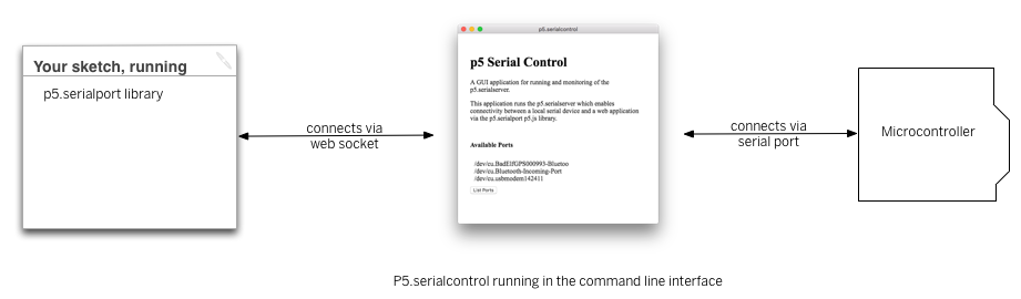
When you use the p5.webserial library for P5.js, it uses the W3C’s WebSerial API to allow your browser to communicate with serial ports on your computer. This lab shows you how to use P5 to control a microcontroller using asynchronous serial communication. WebSerial is currently only available in the Chrome and Chromium browsers and the Microsoft Edge browser, so make sure you’re using one of those to do this lab.
To get the most out of this tutorial, you should know what a microcontroller is and how to program them. You should also understand asynchronous serial communication between microcontrollers and personal computers. You should also understand the basics of P5.js, and should have tried the WebSerial Input to P5.js lab.
Things You’ll Need
For this lab, you’ll need the hardware below,
For this lab, you’ll need the hardware below, and you’ll need the same software setup as the WebSerial Input to P5.js lab: You’ll create a p5.js sketch. You’ll also use the p5.WebSerial library. You can use the p5.js web editor or your favorite text editor for this (the Visual Studio Code editor works well).


Prepare the breadboard
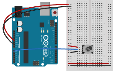
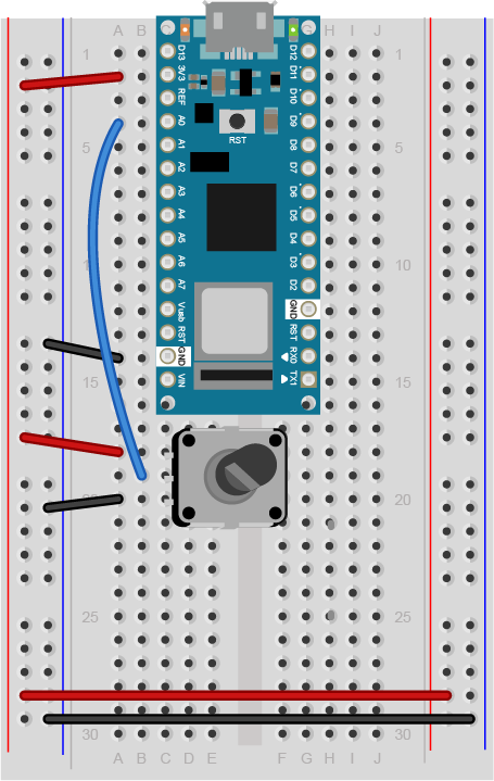
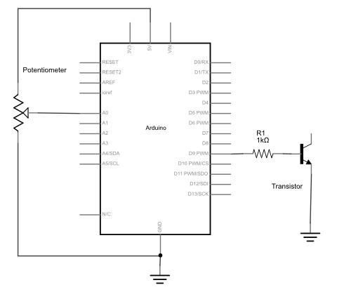
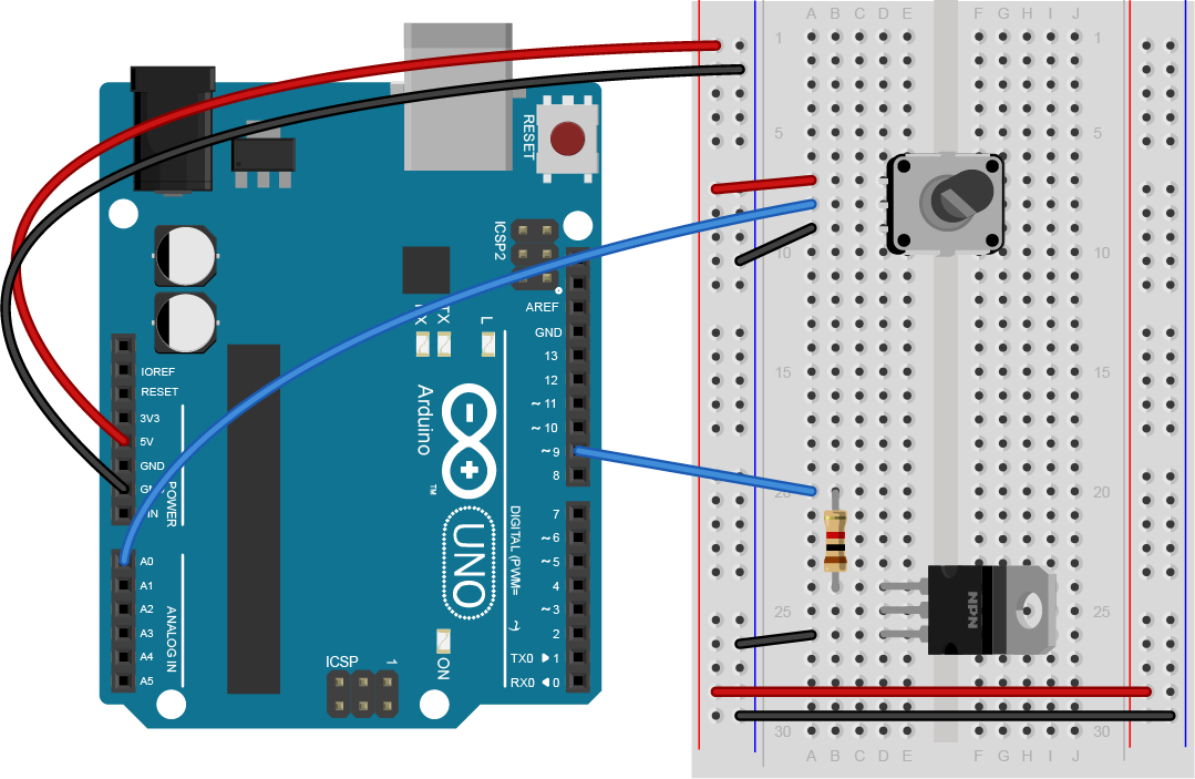
Connect power and ground on the breadboard to power and ground from the microcontroller. On the Arduino Uno, use the 5V and any of the ground connections. On the Nano, use 3.3V and the ground connections:
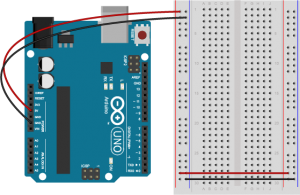

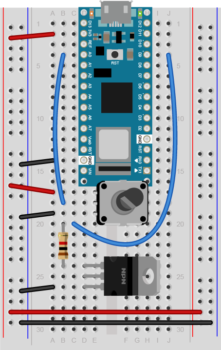
The +3.3 volts and ground pins of the Arduino Nano are connected by red and black wires(Figure 6), respectively, to the left side rows of the breadboard. +3.3 volts is connected to the left outer side row (the voltage bus) and ground is connected to the left inner side row (the ground bus). The side rows on the left are connected to the side rows on the right using red and black wires, respectively, creating a voltage bus and a ground bus on both sides of the board.Figure 5. Breadboard view of an Arduino Nano connected to a breadboard. The +3.3 volts and ground pins of the Arduino are connected by red and black wires, respectively, to the left side rows of the breadboard. +3.3 volts is connected to the left outer side row (the voltage bus) and ground is connected to the left inner side row (the ground bus). The side rows on the left are connected to the side rows on the right using red and black wires, respectively, creating a voltage bus and a ground bus on both sides of the board.
Made with Fritzing
Add an LED
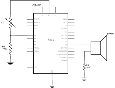
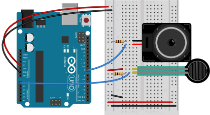
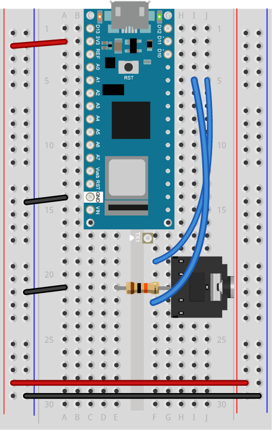
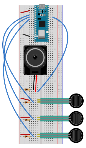
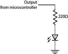
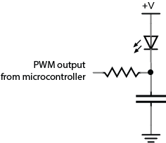
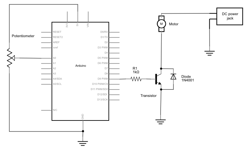
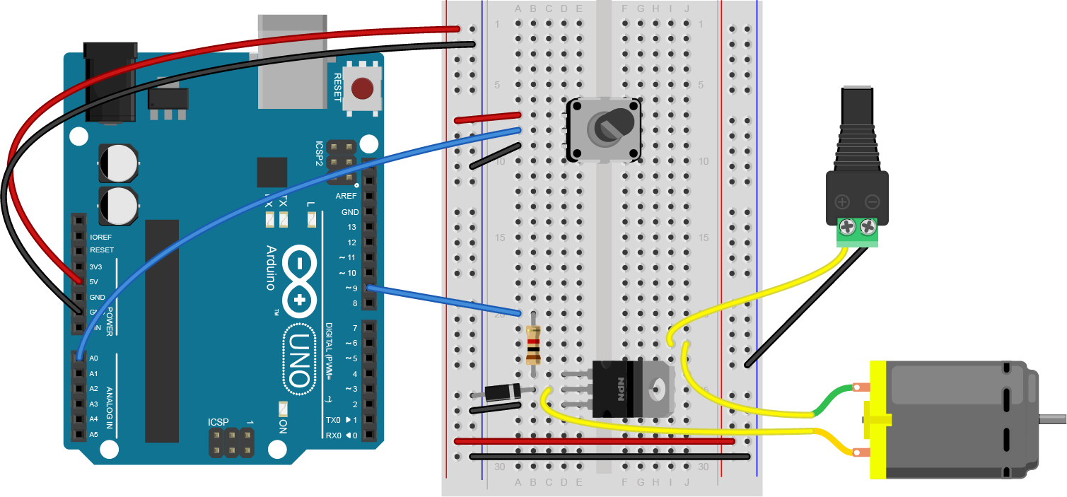
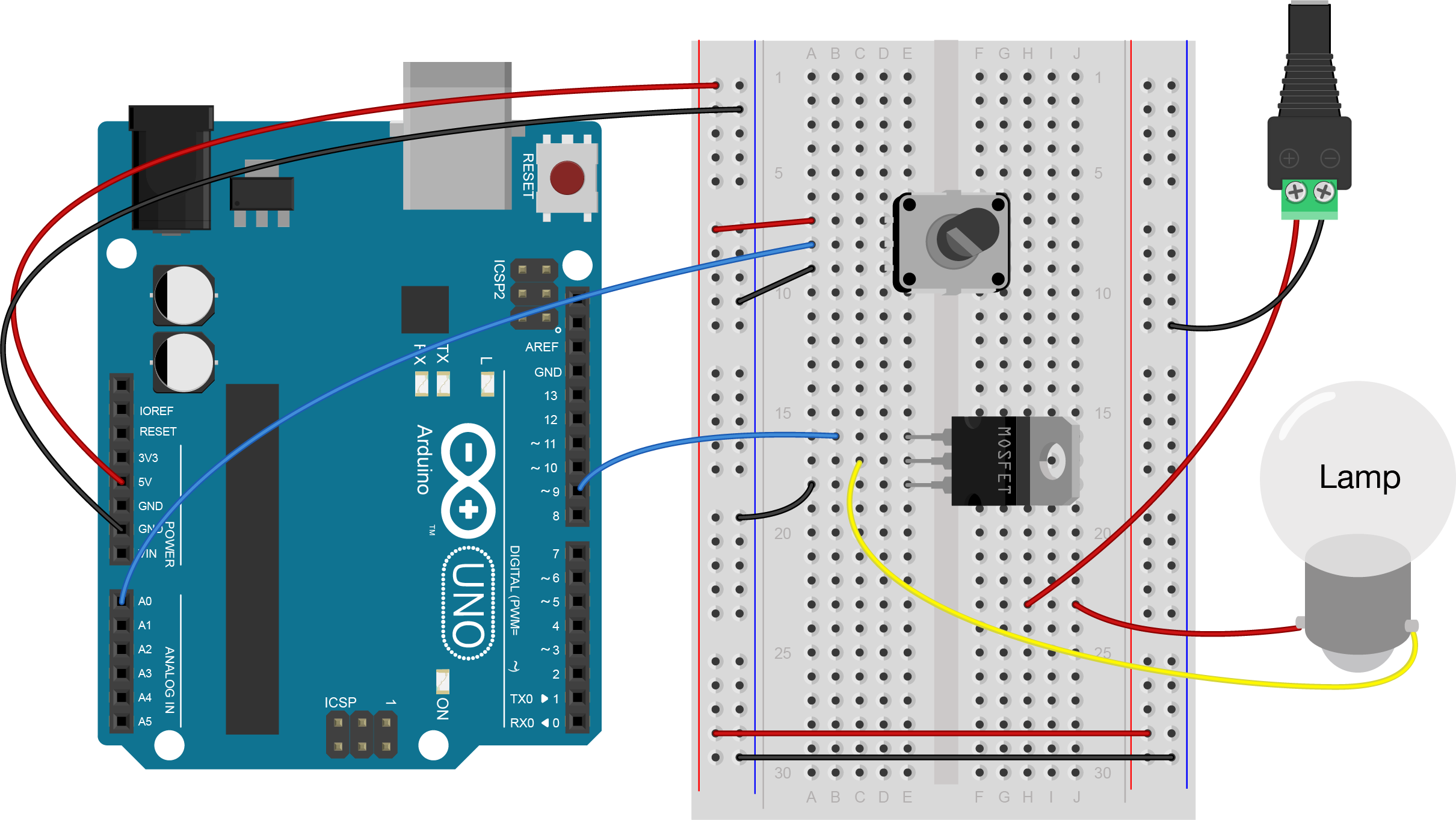
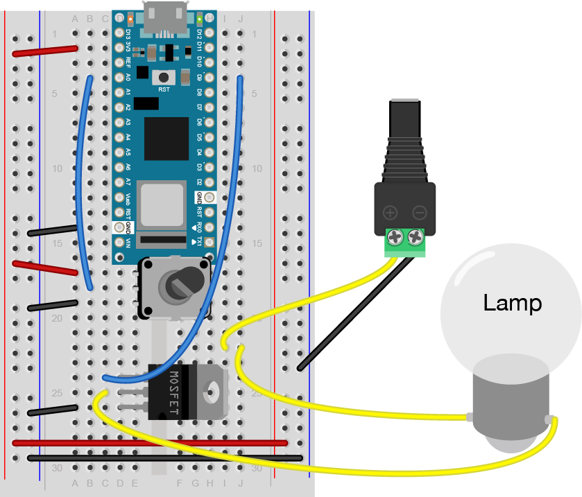
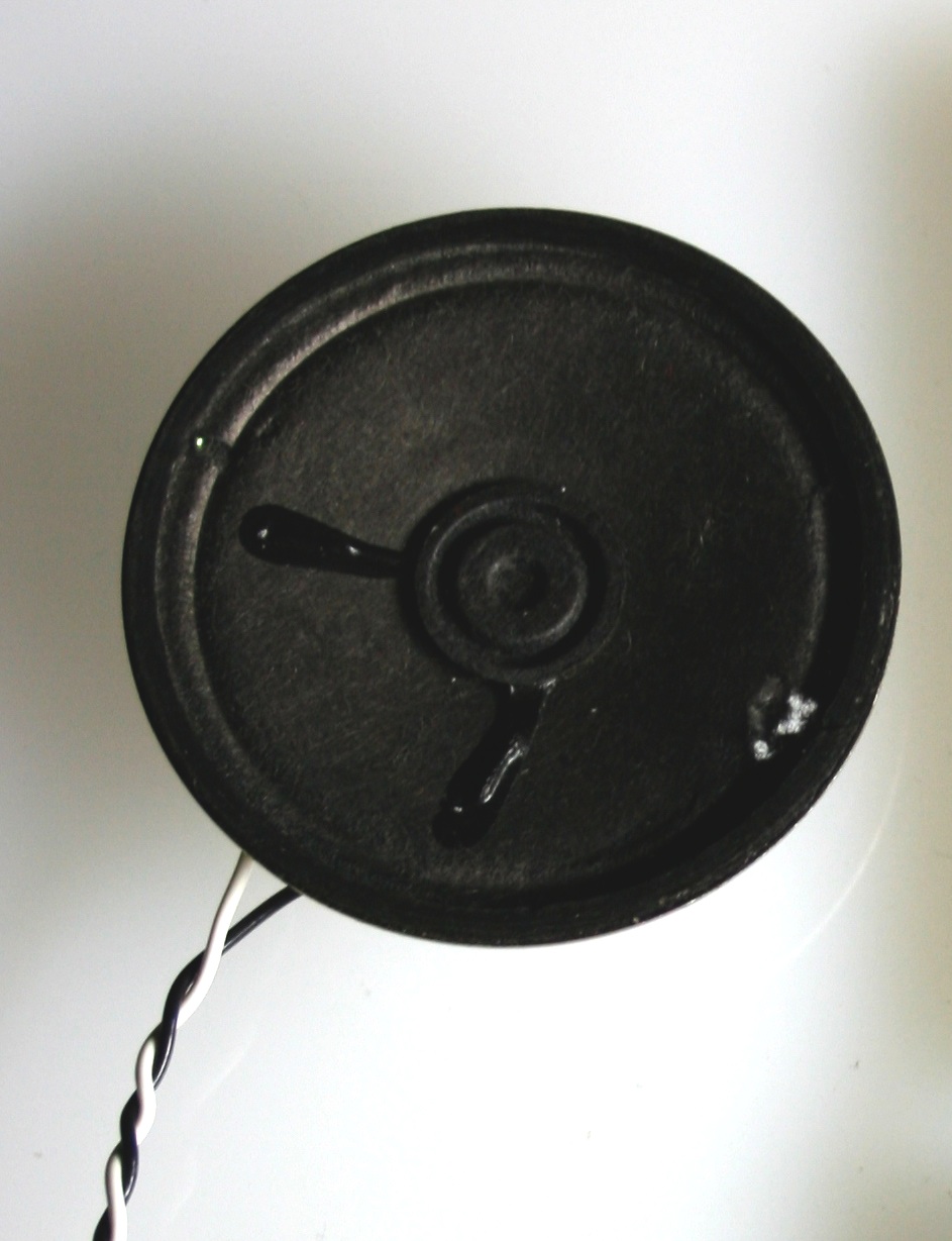
Connect the LED and resistor to digital I/O pin 11 of the module(Figure 7-8). Alternately, you can replace the 220-ohm LED with a speaker (Figure 9-10). You’ll find code below that uses tones instead of LEDs where appropriate. For more on how to do that, see the Tone Output lab:
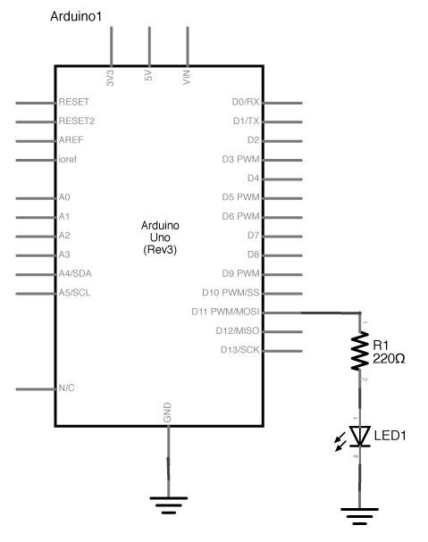
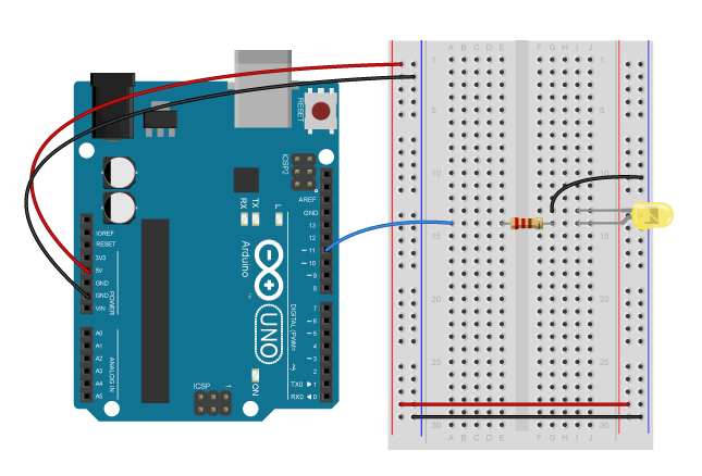
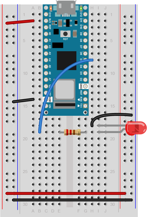
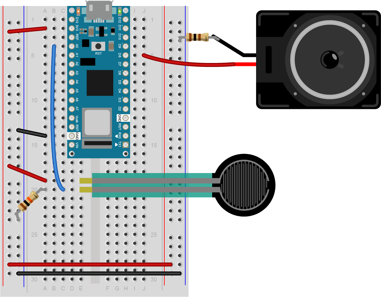
Figure 9 shows a breadboard view of an LED connected to digital pin 5 of an Arduino Nano. The Nano straddles the center of the breadboard in the first fifteen rows. The Nano’s voltage pin (physical pin 2) connects to the board’s voltage bus, and the Nano’s ground pin (physical pin 14) connects to the board’s ground bus. The LED is in the right center of the board, with its anode in one row and the cathode in the next. A 220-ohm resistor connects the LED’s anode to a wire connecting to digital pin 5. The LED’s cathode is connected to the ground bus.
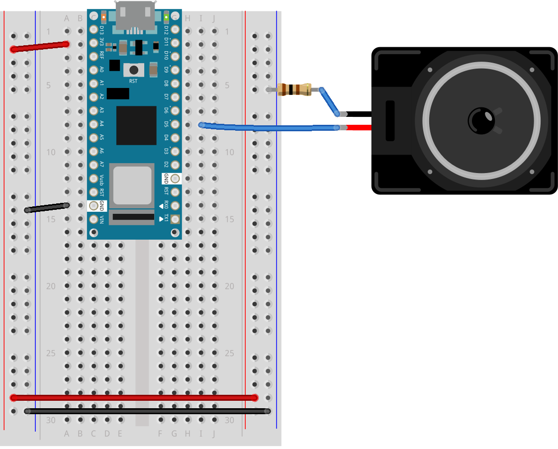
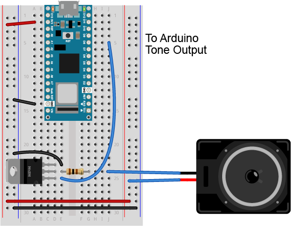
Figure 10 shows a breadboard view of an Arduino Nano connected to a speaker. The Nano’s ground (physical pin 14) is connected to the ground bus of the breadboard as usual. The red positive wire of the speaker is connected to digital pin 5 of the Arduino. The black ground wire of the speaker is connected to one leg of a 100 ohm resistor. The other leg of the resistor connects to ground.
Program the Microcontroller
Program your Arduino to read the analog input as follows:
void setup() {
  Serial.begin(9600);     // initialize serial communications
  pinMode(5, OUTPUT);
}

void loop() {
  if (Serial.available() > 0) { // if there's serial data available
    int inByte = Serial.read();   // read it
    Serial.write(inByte);         // send it back out as raw binary data
    analogWrite(5, inByte);       // use it to set the LED brightness
    // if you're using a speaker instead of an LED, uncomment line below  and comment out the previous line:
    //  tone(5, inByte*10);     // play tone on pin 5
  }
}
Only one port at a time can access a serial port.
As you work on this any microcontroller-to-computer application, you will be switching back and forth between the app that programs the microcontroller (in this case, the Arduino IDE) and the app that the microcontroller is communicating with (in this case, p5.js in the browser). You have to keep in mind that only one of these at a time can access a serial port.
That means that when you want to reprogram your Arduino from the Arduino IDE, you should to stop your sketch in the browser window to do so. Then, restart the browser sketch when you’re done reprogramming the Arduino. You don’t need to quit the Arduino IDE each time, because it knows to release the serial port when it’s not programming. However, you do need to close the Serial Monitor in the Arduino IDE when you are using WebSerial in the browser.
The P5.js WebSerial Library
To communicate with your microcontroller serially, you’re going to use the P5.js WebSerial library. If you’re using the p5.js web editor, make a new sketch. Click the Sketch Files tab, and then choose the index.html file. In the head of the document, look for this line:
<script src="https://cdnjs.cloudflare.com/ajax/libs/p5.js/1.4.0/p5.js"></script>
Right after that line, add this line:
<script src="https://unpkg.com/p5-webserial@0.1.1/build/p5.webserial.js"></script>
The P5.js Sketch
The sketch you’re going to write will control the microcontroller’s LED from P5.js. Dragging the mouse up and down the canvas will dim or brighten the LED, and typing 0 through 9 will set the LED’s brightness in increments from off (0) through almost full brightness (9). There’s an alternate sketch that will make changing tones if you prefer that instead of a changing LED. The sketch will also receive serial input from the microcontroller just as in the WebSerial Input to P5.js lab, so that you can see that the microcontroller is getting the same values you’re sending.
The setup of your sketch will initialize the P5.webserial library and define your callback functions for serial events. Program the global variables and setup() function as follows:
// variable to hold an instance of the p5.webserial library:
const serial = new p5.WebSerial();

// HTML button object:
let portButton;
let inData;                            // for incoming serial data
let outByte = 0;                       // for outgoing data

function setup() {
  createCanvas(400, 300);          // make the canvas
  // check to see if serial is available:
  if (!navigator.serial) {
    alert("WebSerial is not supported in this browser. Try Chrome or MS Edge.");
  }
  // if serial is available, add connect/disconnect listeners:
  navigator.serial.addEventListener("connect", portConnect);
  navigator.serial.addEventListener("disconnect", portDisconnect);
  // check for any ports that are available:
  serial.getPorts();
  // if there's no port chosen, choose one:
  serial.on("noport", makePortButton);
  // open whatever port is available:
  serial.on("portavailable", openPort);
  // handle serial errors:
  serial.on("requesterror", portError);
  // handle any incoming serial data:
  serial.on("data", serialEvent);
  serial.on("close", makePortButton);
}

function draw() {

}
For now you’re leaving the draw() function empty. You’ll fill it in later. You’ll be adding some functions to read mouse dragging and key pressing as well.
Program the handler functions similarly to those in the WebSerial Input to P5.js lab:
// if there's no port selected,
// make a port select button appear:
function makePortButton() {
  // create and position a port chooser button:
  portButton = createButton("choose port");
  portButton.position(10, 10);
  // give the port button a mousepressed handler:
  portButton.mousePressed(choosePort);
}

// make the port selector window appear:
function choosePort() {
  serial.requestPort();
}

// open the selected port, and make the port
// button invisible:
function openPort() {
  // wait for the serial.open promise to return,
  // then call the initiateSerial function
  serial.open().then(initiateSerial);

  // once the port opens, let the user know:
  function initiateSerial() {
    console.log("port open");
  }
  // hide the port button once a port is chosen:
  if (portButton) portButton.hide();
}

// read any incoming data as a byte:
function serialEvent() {
  // read a byte from the serial port:
  var inByte = serial.read();
  // store it in a global variable:
  inData = inByte;
}

// pop up an alert if there's a port error:
function portError(err) {
  alert("Serial port error: " + err);
}

// try to connect if a new serial port
// gets added (i.e. plugged in via USB):
function portConnect() {
  console.log("port connected");
  serial.getPorts();
}

// if a port is disconnected:
function portDisconnect() {
  serial.close();
  console.log("port disconnected");
}

function closePort() {
  serial.close();
}
Program the draw() function to display the value of any incoming serial bytes. Here it is:
function draw() {
  // black background, white text:
  background(0);
  fill(255);
  // display the incoming serial data as a string:
  text("incoming value: " + inData, 30, 30);
}
To read the mouse and keyboard, you’ll need to write functions to respond to the ‘mouseDragged’ and ‘keyPressed’ events. ‘MouseDragged’ will happen whenever you click and drag the mouse on the canvas. When that happens, read the mouseY, and map its position on the canvas to a value from 0 to 255. Convert the result to a number using the int() function. Then send it out the serial port using the serial.write() function:
function mouseDragged() {
  // map the mouseY to a range from 0 to 255:
  outByte = byte(map(mouseY, 0, height, 0, 255));
  // send it out the serial port:
  serial.write(outByte);
}
The serial.write() function is versatile. If you give it a variable or literal that’s a numeric data type, it will send it as its raw binary value. In the code above, note how you’re converting the output of the map() function to a number using the int() function. If you give it a string, however, it will send out that ASCII string. So be aware of the difference, and make sure you know whether your serial receiving device wants raw binary or ASCII-encoded data.
Program the keyPressed() function similarly to the mouseDragged() function. You want it to read the key strokes, convert them to raw bytes, and send them out the serial port. But you only want to send them if they key hit was 0 through 9. The P5.js variable key returns a numeric value, so you can do math on it and convert it like so:
function keyPressed() {
  if (key >= 0 && key <= 9) { // if the user presses 0 through 9
    outByte = (key * 25); // map the key to a range from 0 to 225
    serial.write(outByte); // send it out the serial port
  }
}
That’s all you want your sketch to do, so try running it now. You should see that the initial incoming serial value is undefined, but when you drag the mouse up and down, or type 0 through 9, it will update when the Arduino program returns what it received. The LED will also change with these actions.
You can see this sketch running on gitHub at this link. You can get the full text of it at this link.
Sending ASCII-Encoded Serial Data
When you send data from p5.js using p5.webserial, the serial.write() function works like it does in Arduino: it sends numbers as binary data. In the programs above, you’re sending binary data from p5.js and reading it as binary in Arduino.
If you want to send ASCII-encoded serial data from P5.js instead, all you have to do is to serial.print() or serial.println() your string. On the Arduino side, you can read single characters one byte at a time simply as well. However, if you want to convert multi-byte number strings to numeric values, you’ll need a new function to read ASCII encoded numeric strings called parseInt().
Program the Microcontroller Again
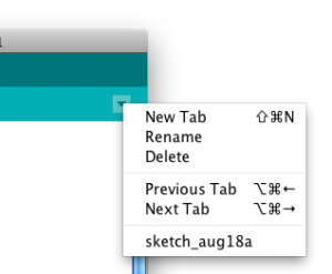
To start off with, load a sketch from the Arduino examples called PhysicalPixel. You can find it in the File Menu -> Examples -> Communication -> PhysicalPixel. Here’s what it looks like. Change the LED pin number to pin 5 as follows:
const int ledPin = 5; // the pin that the LED is attached to
int incomingByte;     // a variable to read incoming serial data into

void setup() {
  Serial.begin(9600);             // initialize serial communication
  pinMode(ledPin, OUTPUT);        // initialize the LED pin as an output
}

void loop() {
  if (Serial.available() > 0) { // see if there's incoming serial data
    incomingByte = Serial.read(); // read it
    if (incomingByte == 'H') {    // if it's a capital H (ASCII 72),
      digitalWrite(ledPin, HIGH); // turn on the LED
      // if you're using a speaker instead of an LED, uncomment line below  and comment out the previous line:
      //  tone(5, 440);           // play middle A on pin 5
    }
    if (incomingByte == 'L') {    // if it's an L (ASCII 76)
      digitalWrite(ledPin, LOW);  // turn off the LED
      // if you're using a speaker instead of an LED, uncomment line below  and comment out the previous line:
      // noTone(5);
    }
  }
}
When you run this, open the serial monitor and type H or L, and the LED will go on or off. Try typing h or l instead. The LED won’t change, because H and h have different ASCII values, as do L and l. But you can see from this that you don’t need to memorize the ASCII chart to check for character values in your code. Put the character you want to read in single quotes, and the Arduino compiler will automatically convert the character to its ASCII value for you. It only works for single characters, though.
Program P5.js To Control the LED
To get P5.js to control this Arduino program serially, you only need to add to the keyPressed() function to read H or L in addition to 0 through 9. Here’s your new mousePressed() function:
function keyPressed() {
  if (key >= 0 && key <= 9) {
    // if the user presses 0 through 9
    outByte = byte(key * 25); // map the key to a range from 0 to 225
    serial.write(outByte); // send it out the serial port
  }
  if (key === "H" || key === "L") {
    // if the user presses H or L
    serial.write(key); // send it out the serial port
  }
}
Because the key is already a single character, P5.js sends it out as is, and Arduino reads it as a single byte, looking for the ASCII value of H or L. Notice how the values returned to P5.js are 72 and 76, the ASCII values for H and L. For single characters like this, exchanging data is simple.
If you tried to change the LED with the mouse, you didn’t see anything happen unless your output value was 72 or 76. Why is that?
To see the sketch running on GitHub at this link. You can see the source files for copying into the p5.js editor at this link.
Processing ASCII-Encoded Strings With Arduino
It is also possible to read and interpret ASCII-encoded strings in Arduino. The String.parseInt() function reads an incoming string until it finds a non-numeric character, then converts the numeric string that it read into a long integer. This is a blocking function, meaning that String.parseInt() stops the program and does nothing until it sees a non-numeric character, or until a timeout passes. The timeout is normally one second (or 1000 milliseconds), but you can set it to a lower number of milliseconds using Serial.setTimeout(). Here’s a variation on the original Arduino sketch from above, using Serial.parseInt() this time:
void setup() {
  Serial.begin(9600);    // initialize serial communications
  Serial.setTimeout(10); // set the timeout for parseInt
  pinMode(5, OUTPUT);
}

void loop() {
  if (Serial.available() > 0) { // if there's serial data available
    int inByte = Serial.parseInt(); // read it
    if (inByte > 0) {
      Serial.write(inByte);      // send it back out as raw binary data
      analogWrite(5, inByte);    // use it to set the LED brightness
      // if you're using a speaker instead of an LED, uncomment line below  and comment out the previous line:
      //  tone(5, inByte*10);     // play tone on pin 5
    }
  }
}
Upload this to your microcontroller, then open the Serial Monitor and send in some ASCII numeric strings. You’ll see the character that’s represented by the string’s value. For example, 65 will return A, 34 will return “, and so forth.Notice that this version of the sketch has a conditional statement to check if the incoming byte is 0. This is because of a quirk of the parseInt() function. It returns 0 if the timeout is hit, or if the string is legitimately 0. This means you can’t really parse for a string like this: "0\n".
Program p5.js To Send a String
Now that your microcontroller is expecting a string, program P5.js to send one. This means changing the mouseDragged() function. Program it to print a string with a newline at the end using the serial.println() command like so:
serial.println(outByte);
Since the newline added at the end by serial.println() is a non-numeric character, the Serial.parseInt() function will see it and parse the string, not waiting for the timeout.
To see the sketch running on GitHub at this link. You can see the source files for copying into the p5.js editor at this link.
Conclusion
When you’re sending data between two computers using asynchronous serial communication, you have to make sure that what the sender is sending is formatted the same as what the receiver is listening for. See Table 1 to review what are suitable data formats for different types/sizes of data and which functions to use on p5.js and Arduino for serial communication.
| Number of Bytes | |||
|---|---|---|---|
| Data to Send | |||
| Send as: | |||
| p5.js -> | (valueToSend + ",") |
||
| -> Arduino | |||
Table 1. Serial Communication: p5.js to Arduino
Think this out in advance before you code, then consider what functions you’ve got on both computers to convert data from strings to raw binary numbers and back. Test with fixed values at first, so you know you’re getting what you think you should. For example, sending an ASCII-encoded numeric string like this:
1023\n
Will always result in these six bytes:
49 48 50 51 10
Likewise, this text string:
Hello\n
will always be:
72 101 108 108 111 10
By sending a string you know both the ASCII and raw binary representations of, you can test your code easier, because what you’re sending won’t change. Once you know the sending and receiving works, then you can send variable strings.
The more you work with serial data, the more you’ll become familiar with the methods for handling it.
For more on serial flow control in P5.js, see the Two-Way Duplex Serial Communication Using p5.WebSerial Lab.