The Arduino Nano R4 is 5-volt microcontroller board in a Nano format. It can do the things that the Arduino Uno can, and it has a number of additional features for physical computing projects. This page introduces some of the functions that this board supports.
Feature Overview
The Nano R4 has a number of useful features, including:
- 8 analog inputs
- 6 PWM outputs
- 1 Digital-to-analog converter (DAC) output
- A real-time clock (RTC) for timekeeping
- An operational amplifier
- HID communication – it can emulate a USB keyboard or mouse
- UART, I2C, SPI, and CAN bus communications
- Qwiic connector for I2C connections
Form Factor
The Nano R4 is based on the original Arduino Nano pin layout. It’s a dual-inline package (DIP) format, meaning it’s got two rows of pins spaced 0.1 inches apart, so it fits nicely on a solderless breadboard. You can get it with or without header pins, and it’s small enough that you can incorporate it in handheld projects as well.
The physical pin numbering for DIP devices goes in a U shape. Holding the micro USB connector at the top, the numbering starts with physical pin 1 on the upper left, counting down the left side to pin 14 on the lower left, then counting from pin 15 on the lower right, to pin 28 on the upper right. For the most part, the left side of the board is power and analog inputs, and the right side is digital I/O pins.
The Nano boards all follow a similar pin layout, as follows, counting from physical pin 1 (upper left) to pin 15 (lower left) across to pin 16 (lower right) to pin 30 (upper right). Figure 1 shows the pin diagram.
- Pin 1: Digital I/O 13
- Pin 2: 3.3V output
- Pin 3: Analog Reference
- Pin 4-11: Analog in A0-A7; Digital I/O 14-21
Pin 12: +5V - Pin 13: Reset
- Pin 14: Ground
- Pin 15:Vin (21V max)
- Pin 16: Digital I/O pin 1; Serial1 UART TX
- Pin 17: Digital I/O pin 0; Serial1 UART RX
- Pin 18: Reset
- Pin 19: Ground
- Pin 20-30: Digital I/O pins 2-12
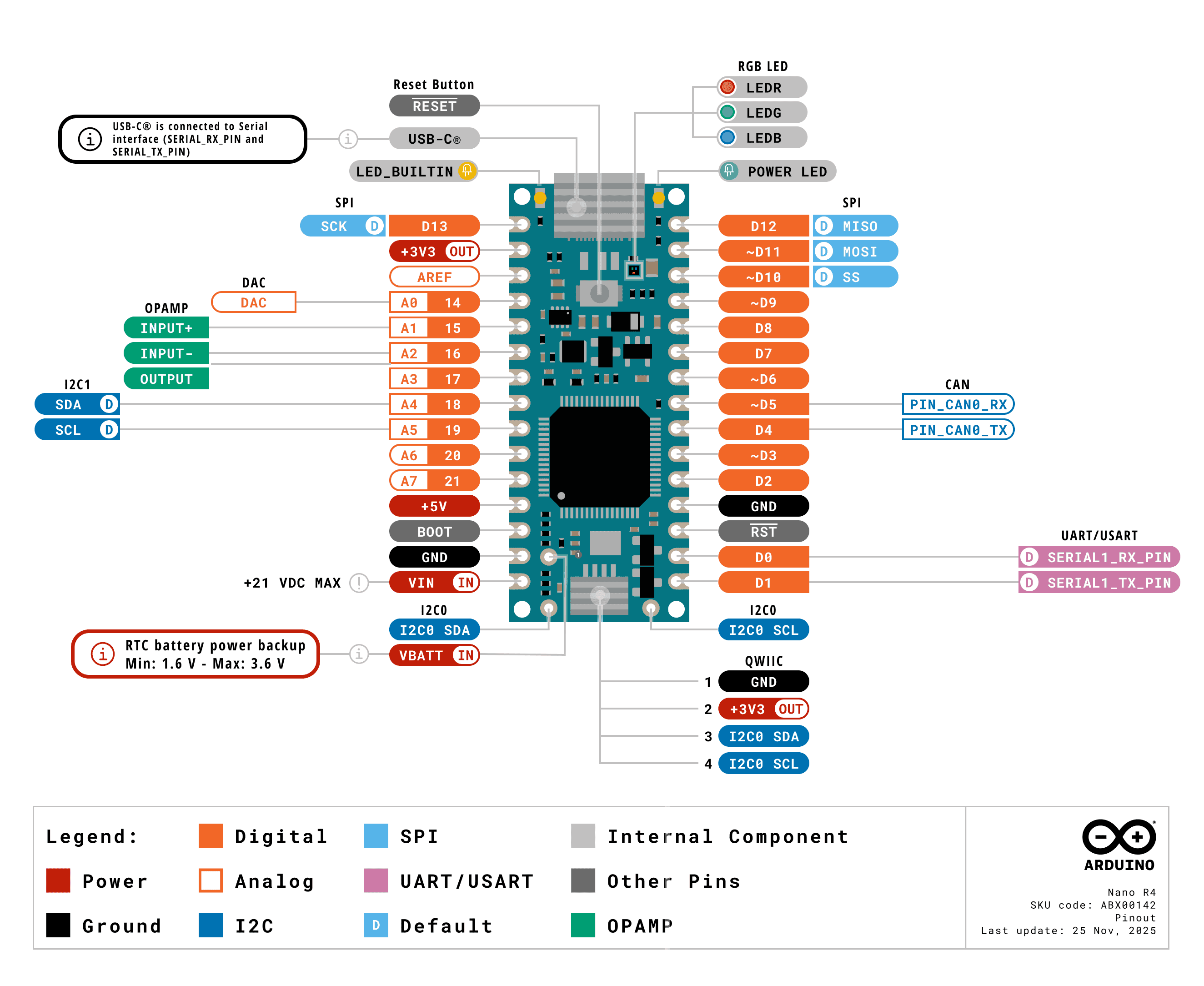
Figure 1. Pin diagram of the Nano R4. Image from the Nano R4 User Manual
The full specifications of the Nano R4 and an official pin diagram can be found on its User Manual page.
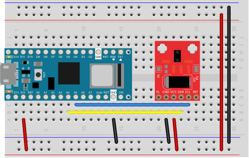
Typical Breadboard Layout
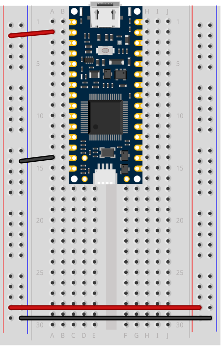
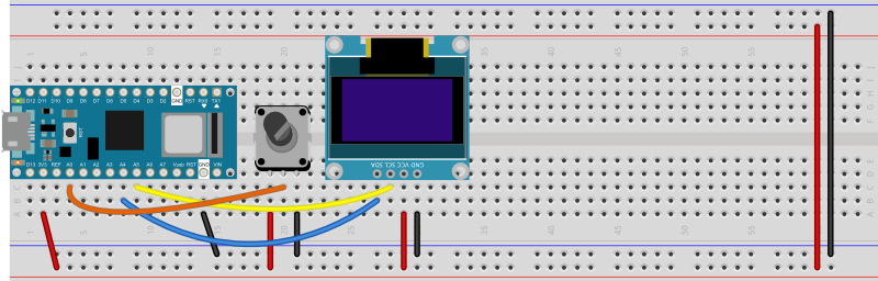
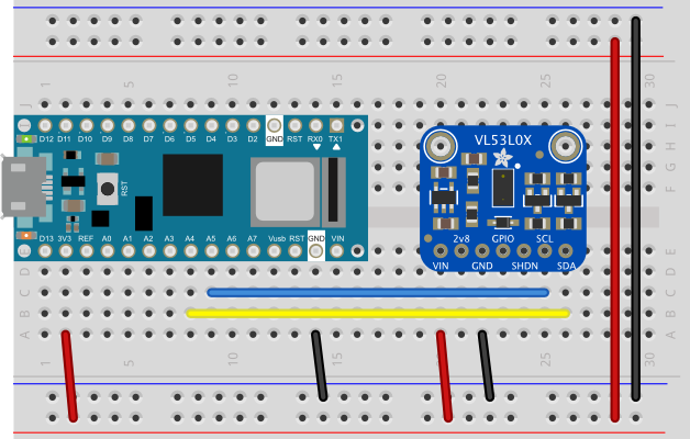
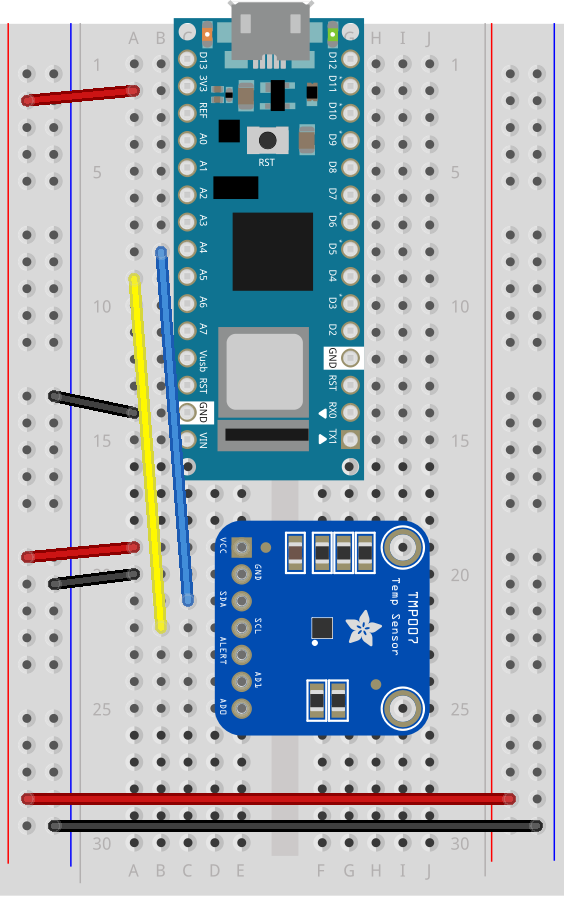
In a typical breadboard layout for the Nano R4, The +3.3 volts and ground pins of the Nano are connected by red and black wires, respectively, to the left side rows of the breadboard. +3.3 volts is connected to the left outer side row (the voltage bus) and ground is connected to the left inner side row (the ground bus). The side rows on the left are connected to the side rows on the right using red and black wires, respectively, creating a voltage bus and a ground bus on both sides of the board. If you are making a 5-volt circuit instead of a 3.3-volt circuit, you can use the +5 volt pin (pin 12) instead of the +3.3 volt pin.
Other board layouts can be found on the Breadboard Layouts page.
Like many microcontrollers these days, the Nano R4 uses a USB-C connector. This is a delicate connector, and you shouldn’t handle the board by the connector. If you are mounting the board in a project box or as a wearable and you are using the USB connection, make sure the cable and the board are mounted so that they won’t move relative to each other.
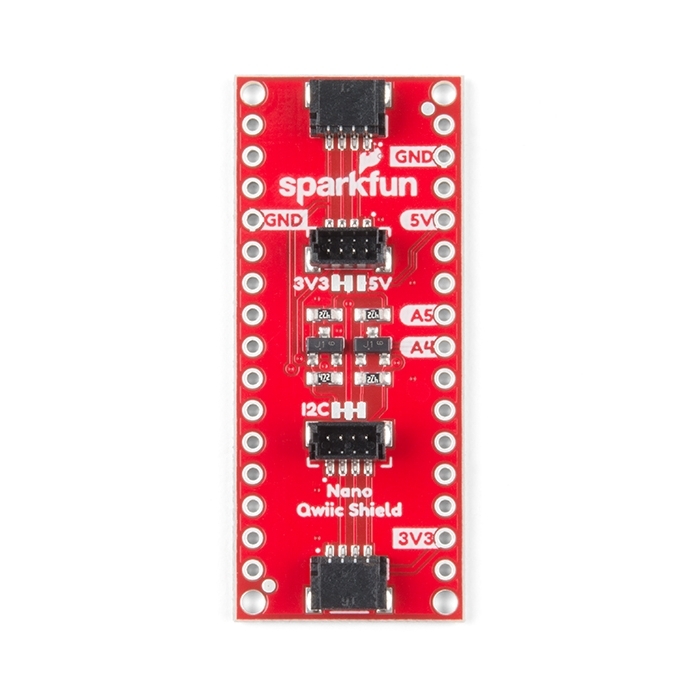
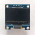
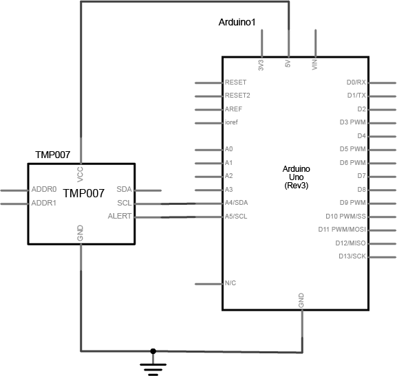
I2C and the Qwiic Connector
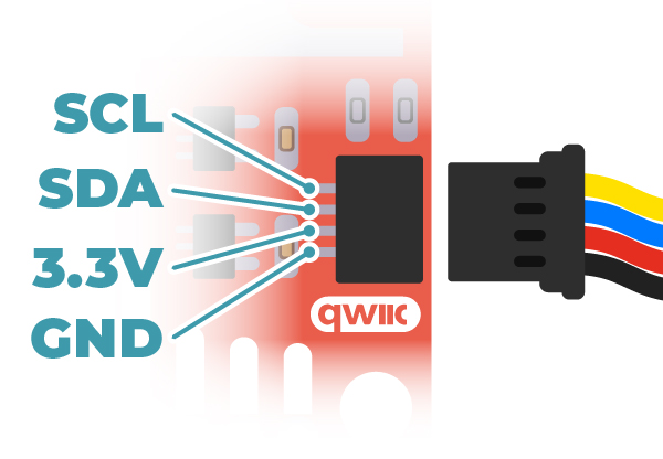
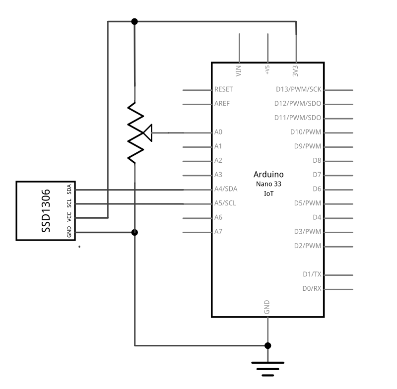
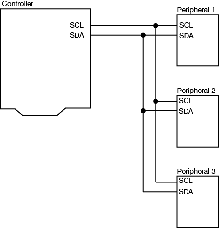
The Nano R4 has two I2C buses. The first I2C bus on pins A4 and A5 operates at +5V, like the Nano R4 itself. This bus can be connected to using the Wire library, as usual. The second I2C bus is connected to the qwiic connector, and operates on +3.3V.
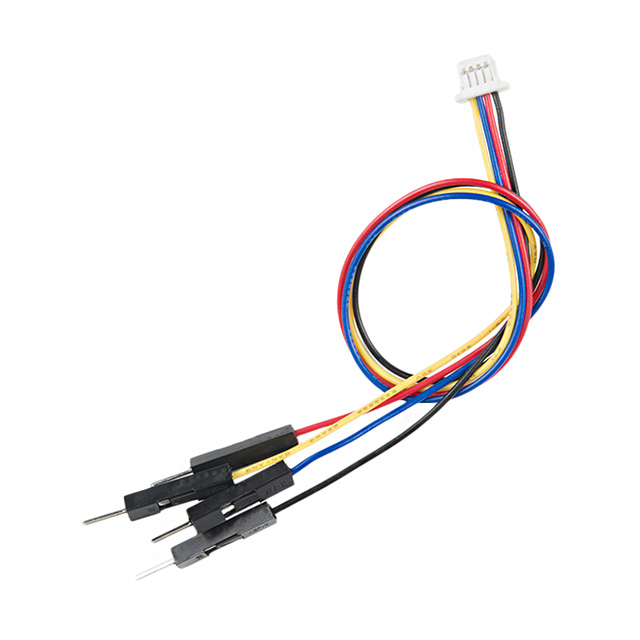
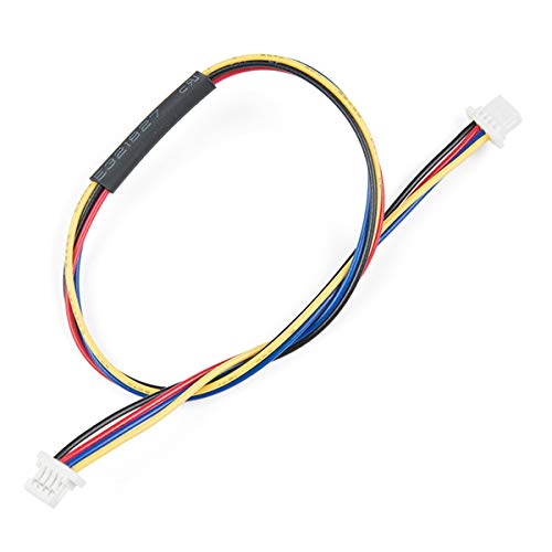
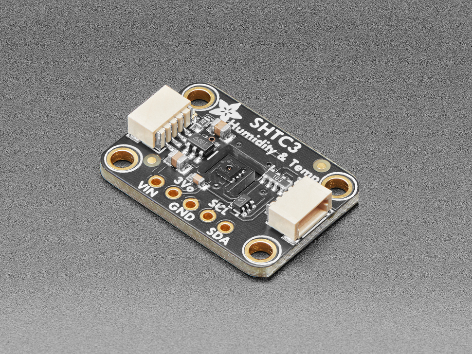
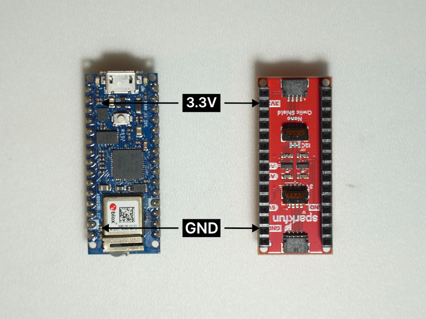
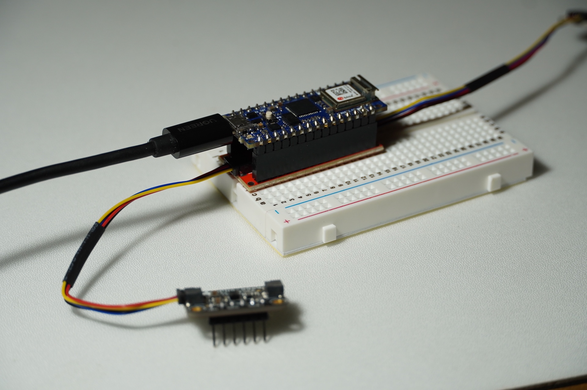
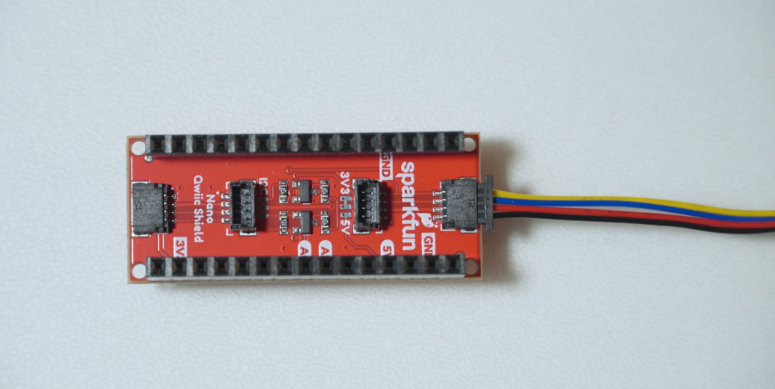
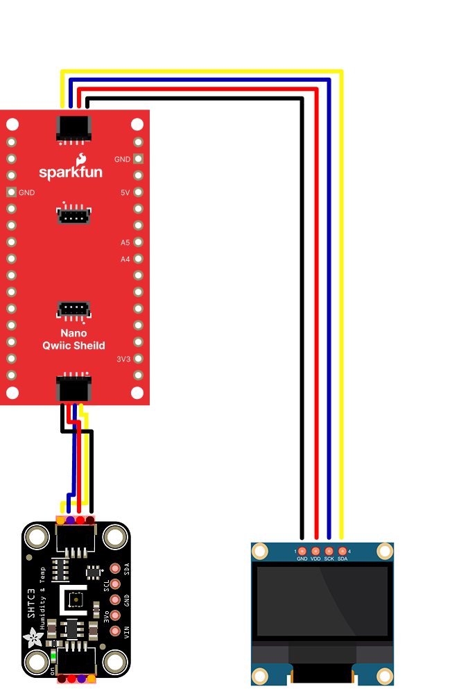
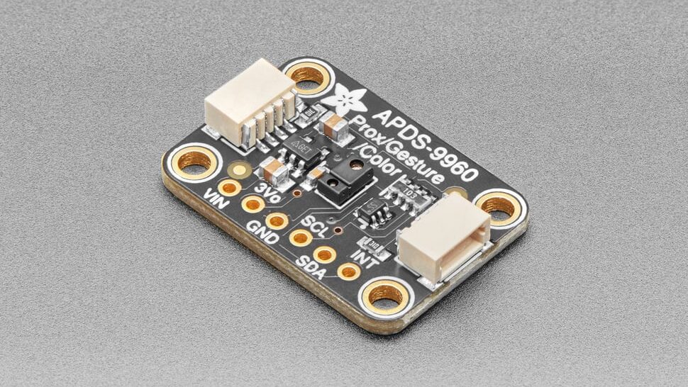
The Qwiic connector, the small rectangular part at the bottom center, gives you an easy way to connect I2C peripherals to your board using Qwiic or Qwiic-compatible connectors. Sparkfun’s Qwiic sensors, Adafruit’s Stemma sensors, and Arduino’s Modulino sensors are all compatible. For more on these, see this section of the I2C introduction. For an example, see this lab on the Sparkfun Qwiic Shield for Nano.
Processor
The Nano 33 IoT has a Renesas R7FA4M1AB3CFM 32-bit processor. It’s considerably faster than the Uno’s processor (48MHz clock speed compared to the Uno’s 16MHz, and a 32-bit processor compared to the Uno’s 8-bit processor) and has more memory (256 kB flash, 32 kB SRAM and 8 kB data memory (EEPROM) compared to the Uno’s 2KB/32KB). That makes for more programming space at a faster speed.
Input and Output (GPIO) Pins
The Nano R4 has 14 digital I/O pins and 8 analog input pins. The analog in pins can also be used for digital in and out, for a total of 22 digital I/O pins. Of those, 6 can be used for PWM out (pseudo-analog out): digital pins 3, 5, 6, 9, 10, and 11. One pin A0, can also be used as a true analog out, because it has a digital-to-analog converter (DAC) attached (here’s an example of how to use it). There are also more hardware interrupt pins than the Uno; pins 0,1,2,3,8,8,12,13, and A1 through A6 can be used as hardware interrupts. Hardware interrupts make it possible to read very fast changes in digital input and output. For example, rotary encoders work best when attached to interrupt pins.
Serial and USB
The Nano 33 IoT is USB-native. That means it can operate as a few different USB devices: asynchronous serial, keyboard or mouse (also known as Human Interface Device, or HID). This is different than the Uno, which has a dedicated USB-to-serial chip on the board, but can only operate as a USB serial device.
There’s also a second asynchronous serial port on pins 0 and 1 that you can use for connecting to other serial devices while still connecting to your personal compuuter. The serial port on pins 0 and 1 is called Serial1, so you’d type Serial1.begin(9600) to initialize it, for example.
Real-Time Clock
The Nano R4 also has a real-time clock module built into the processor, which is accessible using the RTC library that also works on the Uno R4. With this, you can keep track of hours, minutes and seconds much easier. As long as the board is powered, the realtime clock will keep time. Like all libraries, it comes with examples when you install it.
Scheduler
The Nano 33 IoT can run multiple loops at once, using the Scheduler library. When you’ve got an application that needs two or more independent loop functions, this can be a quick way to do it.
Uploading to the Nano R4
If you’ve used an Uno before, and are migrating to the Nano R4 board, you may notice that the serial connection behaves differently. When you reset the MKR, Nano, or Leonardo boards, or upload code to them, the serial port seems to disappear and re-appear. The newer boards can communicate natively using USB, unlike the Uno R3. They don’t need a separate USB-to-serial chip. Because of this, they can be programmed to operate as a mouse, or as a keyboard. Since they are USB-native, their USB connection gets reset when you upload new code or reset the processor. That’s normal behavior for them; it’s as if you turned off the device, then turned it back on. Once it’s reset, it will let your computer’s operating system know that it’s ready for action, and your serial port will reappear. This takes a few seconds. It means you can’t reset the board and then open the serial port in the next second. You have to wait those few seconds until the Arduino board has made itself visible to the computer’s operating system again.
If you’re doing keyboard or mouse, the serial port number will also change when you add those functions. You’ll still be able to send and receive serial data as usual, but you’ll have to re-choose the port in the Boards -> Port submenu after you program your Nano to be a HID device.
If you have trouble getting the Nano R4 to appear in the Arduino IDE, double-tap the reset button at the top center of the board. This will put the board into bootloader mode, meaning that it will show up as a serial device, but not start running the sketch yet. This mode also makes it easier to recover your board if you write a sketch you can’t control, such as a runaway mouse sketch.