Introduction
Playback of digital sound files is a popular use of microcontrollers. The Inter-IC Sound (I2S) protocol makes this possible. In this lab, you’ll learn how to use the I2S bus on the Arduino Nano 33 IoT in combination with the SPI bus to read a .wav sound file from a microSD card and play it on an I2S-compatible amplifier.
What is I2S?
I2S, the Inter-IC Sound protocol, is a serial protocol used for connecting digital audio devices. I2S allows you to transmit Pulse-Code Modulated (PCM) audio data between integrated circuits, like a microcontroller and a digital amplifier. The Arduino site offers a brief introduction to I2S, and Wikipedia has a good definition page on I2S as well. Though it’s not the only means of transmitting digitized audio from one component to another, it is a popular one.
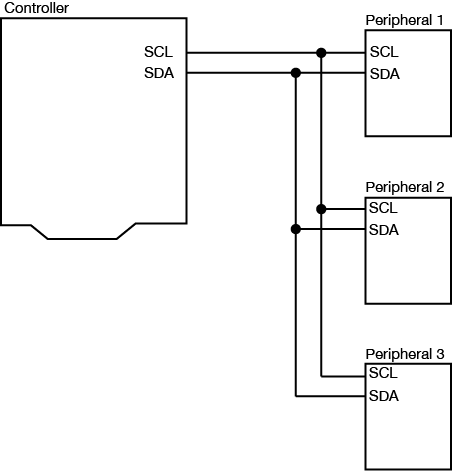
Don’t confuse I2S with I2C, the inter-integrated circuit protocol. Both are synchronous serial protocols, but with different purposes. You can learn about I2C in these labs.
This will not work on the Uno. It will only work on the Nano 33 IoT and the MKR series Arduino boards, which have an I2S bus built in. The Arduino I2S and the ArduinoSound libraries support I2S.
The material in this lab is adapted from Tom Igoe’s SoundExamples page.
What You’ll Need to Know
To get the most out of this Lab, you should be familiar with the basics of programming an Arduino microcontroller. If you’re not, review the Digital Input and Output Lab, and perhaps the Getting Started with Arduino guide. You should also understand asynchronous serial communication and how it differs from synchronous serial communication. You should also know how to communicate with a microSD card from an Arduino using the SPI protocol.
Things You’ll Need
Figures 1-8 list the components you will need.


The Circuit
The circuit for this lab consists of:
- the microcontroller
- a microSD card breakout
- an I2S audio amp breakout.
You’ll also need a microSD card reader for your personal computer.
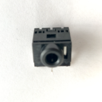
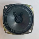
The lab has been tested with two different amps, the UDA1334 breakout board from Adafruit, and the MAX98357A breakout board from Sparkfun. Both work just the same, but the Sparkfun amp needs an additional component, a 3.5mm audio hack.You’ll need to attach wires to connect to a stereo mini jack, as shown here, or you’ll need to solder a speaker onto the + and – holes of the breakout board. The Adafruit board has a built-in jack.
Connect the SD Card Breakout Board
The microSD card in this lab is for storing the .wav files that you want to play. You can playback from multiple files with the libraries used in this project.
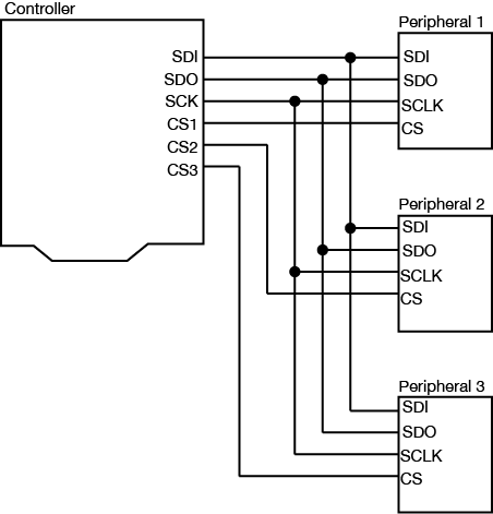
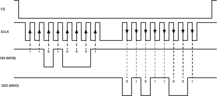
SD cards use the Serial Peripheral Interface (SPI) protocol to communicate with microcontrollers and other computers. SPI is a synchronous serial protocol that supports two-way communication between a controller device such as a microcontroller and a peripheral device like an SD card reader. All SPI devices have a common set of connections:
- a Serial Data In (SDI) connection, on which the controller sends data to the peripheral devices.
- a Serial Data Out (SDO) connection, on which the peripheral devices send data to the controller.
- a Serial Clock (SCLK) connection, on which the controller sends a regular clock signal to the peripheral devices.
- one or more Chip Select (CS) connections, which the controller uses to signal the peripheral devices when to listen to incoming data and when to ignore it.
The SDO of a controller connects to the SDI of a peripheral, and vice versa.
The SPI pin numbers are the same numbers for the Uno and Nano 33 IoT, as follows:
- SDO – pin 11
- SDI – pin 12
- SCK – pin 13
- CS – pin 10
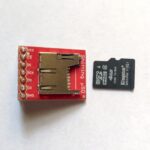
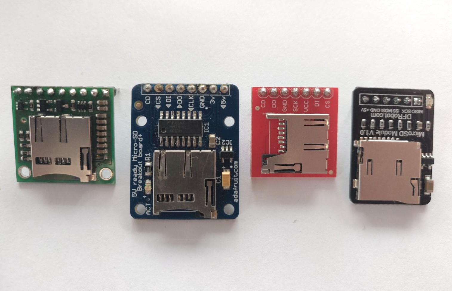
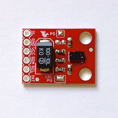
The MicroSD card reader/writer shown in Figure 4 is from Sparkfun. It has level-shifting circuitry built-in to adjust for either 3.3- or 5-volt operation. They have a second model which is shown in Figure 9 was the model for the breadboard drawing in Figure 10. Both will work with this lab. There are many other models on the market though. Here’s an Adafruit model. Here’s a Pololu model. Here’s a DFRobot model. All of them will communicate with your microcontroller in basically the same way, though, using the SPI pin connections.
Most SD card readers have a card detect (CD) pin as well, that changes state when the card is inserted or removed. It’s optional, but it can be useful to make sure you have a card in the reader. It’s not used in this example. You will see differing names for the SPI pins as the names as manufacturers modernize their naming conventions. As a result, different breakout boards may have different labels. Make sure to match up the pin functions, not just the pin numbers. Figure 9 shows several models, and you can see that the pin naming conventions and pin positions differ from one model to the next.
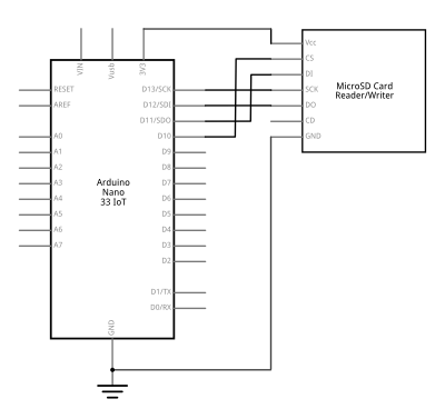
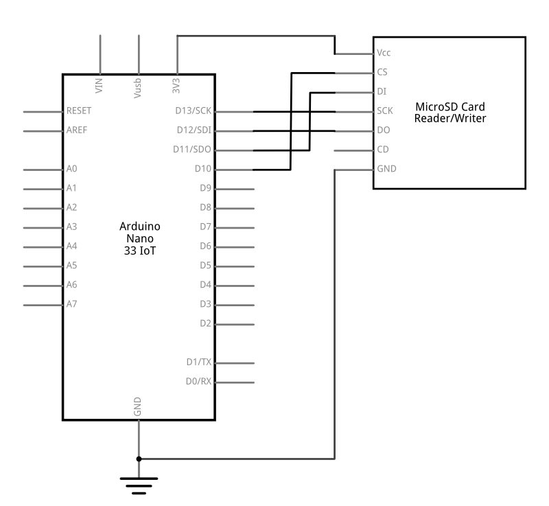
Connect your Arduino to the SD card reader as shown in Figure 10 and 11. If you’re using the Sparkfun SD card reader/writer, the pins are on the on the left side of the board, and they’re numbered, from top to bottom, as follows:
- Vcc – voltage in. Connects to microcontroller voltage out
- CS – Chip select. Connects to microcontroller CS (pin D10 on the Nano/Uno)
- DI – SPI data in. Connects to microcontroller SDO (pin D11 on the Nano/Uno)
- SCK – SPI clock.. Connects to microcontroller SCLK (pin D13 on the Nano/Uno)
- DO – SPI data out. Connects to microcontroller SDI (pin D12 on the Nano/Uno)
- CD – card detect. Not connected in this example
- GND – ground. Connects to microcontroller ground
Connect the I2S Amplifier
The I2S amplifier takes the digitized audio signal from your microcontroller and converts it to an analog audio signal that can play on analog speakers or headphones. The connections for an I2S bus are:
- Serial clock (SCK) or Bit Clock (BCLK) – This is the line that carries the clock signal
- Frame Select (FS), also called Word Select (WS or WSEL), or Left-Right Clock (LRC) – This determines left and right channels
- Data, also called Digital Out (DOUT) or Digital In (DIN) depending on the application – This is the data signal itself.
The controlling device sends the clock signal, just like in other synchronous serial protocols like I2C and SPI.
Connect the I2S amp to your Arduino as follows:
- BCLK connects to A3 of the Nano 33 IoT board
- LRC connects to A2 of the Nano 33 IoT board
- DIN connects to D4 (SDA Pin) of the Nano 33 IoT board
- Vin connects to 3.3V
- GND connects to ground
- + connects to the left and right sides of a 3.5mm audio jack
- – connects to the center pin of a 3.5mm audio jack
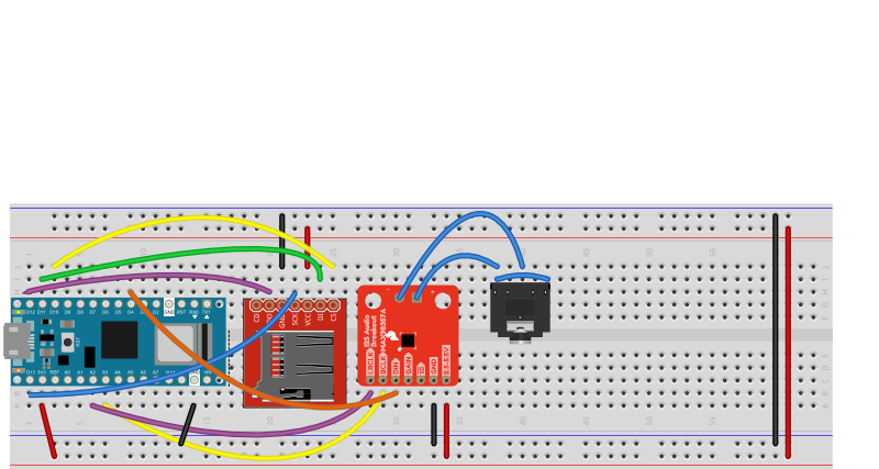
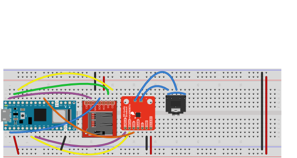
This wiring is shown in Figures 12 and 13 with a MAX98357 I2S audio amplifier and audio jack. You have to attach a 3.5mm audio jack to the amplifier separately. The photo in Figure 6 shows a jumper wire cut in half and soldered to the + and – terminals of the audio amplifier to make it easier to connect to a 3jack via a breadboard.
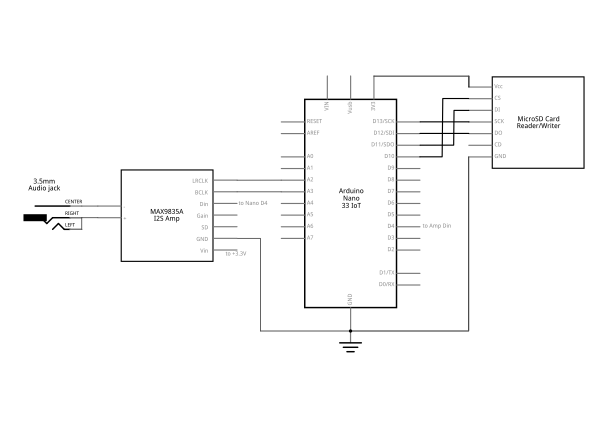
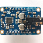
The connections for the Adafruit UDA1334 I2S amp are similar, but the pins have different names:
- BCLK connects to A3 of the Nano 33 IoT board
- WSEL connects to A2 of the Nano 33 IoT board
- DIN connects to D4 (SDA Pin) of the Nano 33 IoT board
- Vin connects to 3.3V
- GND connects to ground
The UDA1334 amp has a built-in 3.5mm audio jack, so there’s no need to wire a separate jack as there is with the previous amp.
Once you’ve connected the MicroSD card and amplifier, your circuit is ready.
Format the MicroSD card
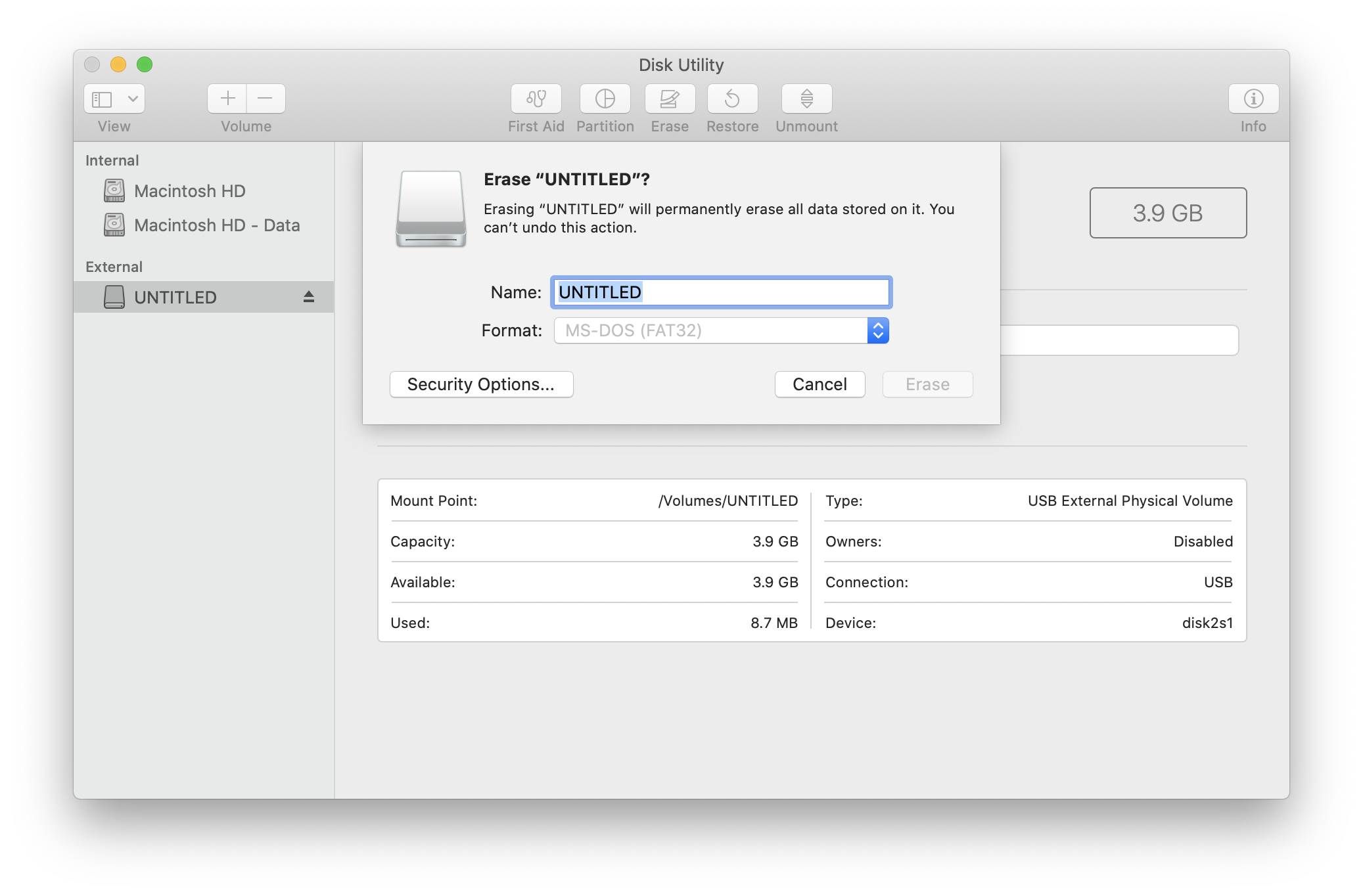
Your SD card needs to be formatted as FAT32 or FAT16. The SD Card Lab has notes on how to do this. There are also instructions on the Arduino site on formatting your card, as well as the Adafruit site. If you’re formatting on MacOS, you can use the DiskUtility app, but you must format your disk as MS-DOS (FAT). You should test the SD card for reading and writing first.
Your filename needs to correspond to 8.3 naming, so it should be no more than 8 characters long, with the extension .wav at the end.
Make A .WAV file
The ArduinoSound library can only play audio files formatted as .wav files, because these are uncompressed audio files. The .wav file must be formatted as stereo, signed 16-bit, 44100Hz. There’s a good tutorial on the Arduino site on how to do this using the free audio editing software Audacity. Once you’ve made your file, copy it to the SD card.
Program the Microcontroller
The ArduinoSound library comes with a and example called WavePlayback to get you started. Here are a few of the important parameters you should know about:
You’ll make an instance of the SDWaveFile class to read the file from the SD card. From that, you can get the file duration, sample rate, bits per sample, channels, current time, and more. It’s useful to print out one of these properties, like the file duration, when you open it, to see that things are working.
The AudioOutI2S class gives you control over playback. You can check if the output can play, and you can play, pause, loop, resume, stop the playback. You can also check whether the file is playing or paused and you can set the volume.
Import the Library
Download the ArduinoSound library on your Arduino IDE. You can find it in the Library Manager of the IDE (Sketch Menu -> Include Library -> Manage Libraries, search for “ArduinoSound”). At the start of your sketch, import the libraries and set up a variable to hold the SDWaveFile instance like so:
#include <SD.h>
#include <ArduinoSound.h>
#define I2S_DEVICE 1   // this enables the I2C bus

// filename of wave file to play
// file name must be 8 chars (max) .3 chars
const char filename[] = "MUSIC.WAV";

// variable representing the Wave File
SDWaveFile waveFile;
// timestamp for printing the current time:
long lastPrintTime = 0;
Initialize the SD card
In the setup, you need to check that the components are working. If any of them fail, it’s a good idea to stop and notify the user. Since there’s no user interface in this basic sketch, you’ll use the Serial Monitor.
First, check that the SD card works:
void setup() {
  // Open serial communications:
  Serial.begin(9600);
  // wait for serial  monitor to open:
  while (!Serial);

  // setup the SD card.
  Serial.print("Initializing SD card...");
  if (!SD.begin()) {
    Serial.println("SD card initialization failed!");
    while (true); // do nothing
  }
  Serial.println("SD card is valid.");
Open the .wav File
Once you know the SD card is good, open the file as a .wav file and check that it can play:
// create a SDWaveFile
  waveFile = SDWaveFile(filename);

  // check if the WaveFile is valid
  if (!waveFile) {
    Serial.print("There is no .wav file called ");
    Serial.println(filename);
    while (true); // do nothing
  }
  // print the file's duration:
  long duration = waveFile.duration();
  Serial.print("Duration = ");
  Serial.print(duration);
  Serial.println(" seconds");

  // check if the I2S output can play the wave file
  if (!AudioOutI2S.canPlay(waveFile)) {
    Serial.println("unable to play wave file using I2S");
    while (true); // do nothing
  }
Set the Volume
Once you know the file’s good to play, set the volume and start playing. The AudioOutI2S.volume() function takes levels from 0-100. This will end the setup() function:
 // set the playback volume:
  AudioOutI2S.volume(80);
  // start playback
  Serial.println("playing file");
  AudioOutI2S.play(waveFile);
What To Do While While Playing
While the file is playing, you don’t need to do anything. It will play regardless of what you are doing in the loop() function. However, you can check to see if it is playing or paused, and you can check the current time. These can be useful for user interface actions like responding to a play/pause button, changing the volume, and so forth.
void loop() {
  if (millis() - lastPrintTime > 1000) {
    Serial.print(waveFile.currentTime());
    Serial.println( " seconds");
    lastPrintTime = millis();
  }
  if (!AudioOutI2S.isPlaying()) {
    Serial.println("File has stopped");
    while (true); // do nothing
  }
  if (AudioOutI2S.isPaused()) {
    Serial.println("File is paused");
  }
}
With that much code, you’ve got enough to play a file. You can find the complete sketch at this link. Upload this sketch to your Nano and connect a headphone or speaker via a cable to the 3.5mm audio jack. Once you open the Serial Monitor, the setup messages will print to let you know things are working, and then current time in seconds will print until the song is done. Then the sketch will stop and do nothing.
The AudioSound library gives you a lot of capability to build .wav file playback devices. Try building a simple audio player with play/pause/rewind buttons. Add a button to skip to the next track. Or try building a sample player that lets you play short files like instrument notes.


