Stepper motors are useful for when you need to rotate a full 360 degrees, but need to position your motor at a particular angle. What follows is a more detailed introduction to unipolar and bipolar stepper motors and how to control them from a microcontroller. In order to get the most out of these notes, you should know something about how electricity works, and you should know the basics of how a microcontroller works as well. You should also understand how transistors are used to control high-current loads. You should also understand how DC motors work.
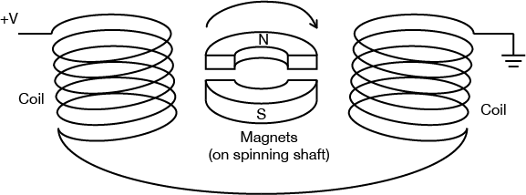
As you learned in the introduction to motors, stepper motor is a motor controlled by a pair of electromagnetic coils. The center shaft has a series of magnets mounted on it, and the coils surrounding the shaft are alternately given current or not, creating magnetic fields which repulse or attract the magnets on the shaft, causing the motor to rotate.
There are two basic types of stepper motors, bipolar steppers and unipolar steppers. A bipolar is the simpler kind of stepper motor; it’s simply two coils, and has four wires. Depending on which coil you put power through, and which direction you send the power in, you step the motor one step forward or back. A unipolar stepper is slightly more complex. It also has two coils, but the centers of the coils are joined in a single junction. This effectively creates four coils, depending on how you put electrical energy through it.
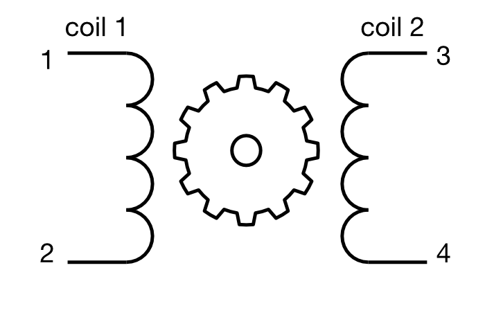
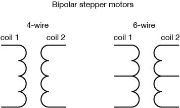
A bipolar stepper motor usually has four wires coming out of it. It has two independent coils. Figure 1 shows a typical bipolar stepper with four wires. In the center is the motor’s shaft, which has a cog-like rotor on it. Each tooth of the cog is magnetized, and every cog’s magnetic polarity is opposite the one next to it.When you put voltage and current through one coil, it turns the central rotor a few degrees, because the magnets on the rotor are attracted to the magnetic field generated by the coil. When you turn that coil off and the other one on, the motor moves a few degrees more.
Figure 1. Wiring for a bipolar stepper motor.
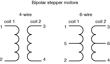
To use a bipolar stepper, you need to know which wire is connected to which coil. You can determine this by measuring the resistance between pairs of wires. When you’ve got the leads of your meter connected to two wires on opposite coils, you should see infinite resistance, or no continuity. When your meter leads are on the same coil, you’ll be able to read the coil’s resistance. The two coils should have the same resistance.
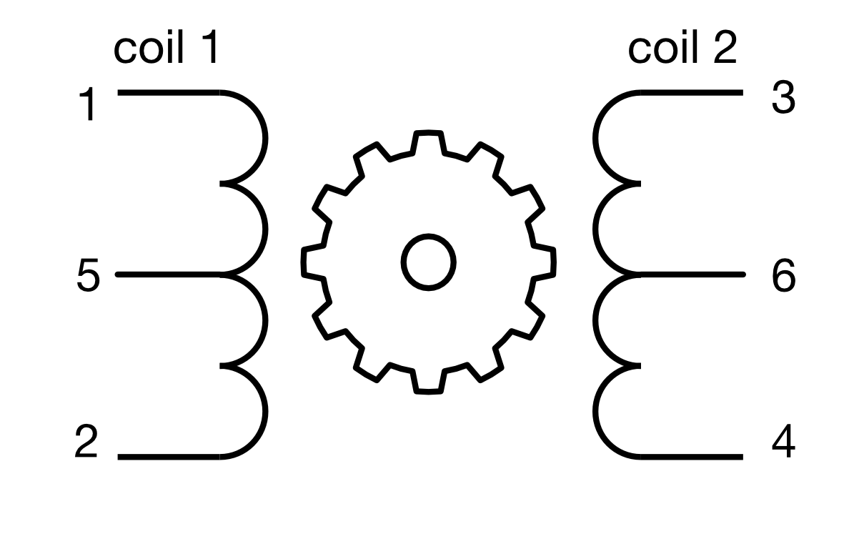
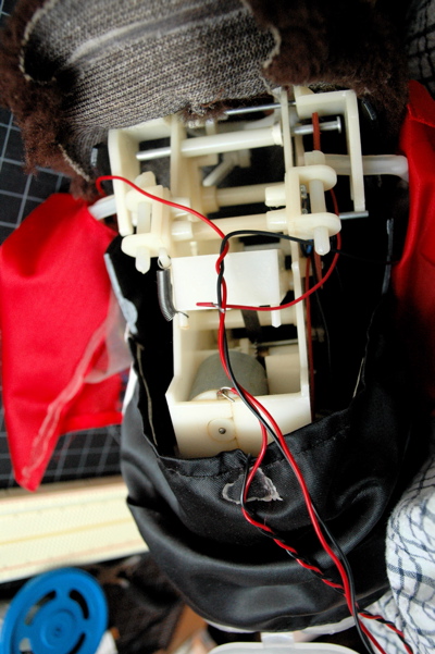
Some bipolar steppers have a center connection on each coil. This allows for finer control over the motor, by treating each half coil as its own coil, as shown in Figure 2. These center connections can be joined to turn a 6-wire bipolar stepper into a unipolar stepper as well. Figure 3 shows the inside of a typical bipolar stepper motor.
Figure 2. a six-wire bipolar stepperFigure 3. Inside a Stepper motor. In this photograph, you can see the inside of a bipolar stepper. The two coils are actually divided into eight sub-coils for finer control. You can see the cog in the center as well. Each tooth on the cog is a tiny magnet.
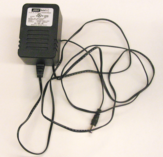
Like other motors, stepper motors require more power than a microcontroller can give them, so you’ll need a separate power supply for them. Ideally you’ll know the voltage and load current from the manufacturer. If not, get a variable DC power supply, apply the minimum voltage (hopefully 3V or so), apply voltage across two wires of one coil (e.g. 1 to 2 or 3 to 4) and slowly raise the voltage until the motor is difficult to turn. It is possible to damage a motor this way, so don’t go too far. Typical voltages for a stepper might be 5V, 9V, 12V, 24V. Higher than 24V is less common for small steppers, and frankly, above that level it’s best not to guess.
Unipolar Stepper Motors
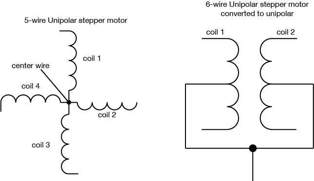
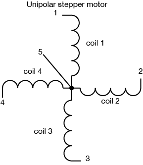
Unipolar steppers motor have five or six wires. The five-wire version has four coils which are all connected on one pole. Six-wire motors are actually bipolar steppers with two coils divided by center connections on each coil, as described above. The center connections of the coils are tied together as shown in Figure 4 and sometimes used as the power connection.
Figure 4. The wiring for unipolar stepper motors. The center wires for the two coils are tied together in a unipolar stepper.
Common Stepper Motor Types
There are two common families of stepper motor that you’ll encounter: NEMA motors and can-stack or tin-can steppers. The labs on this site can work with either. NEMA motors are designed according to a standard set by the US National Electrical Manufacturers Association. These are high-quality motors, and usually the more expensive that you’ll find. The number in a NEMA motor’s designation indicates the motor’s size. A NEMA-11 motor, for example, has a mounting face that’s 1.1 inches square; NEMA-23 is 23 step motor is 2.3 inches square and so forth. Electromate.com has a detailed explanation of NEMA motors if you ‘d like more detail.
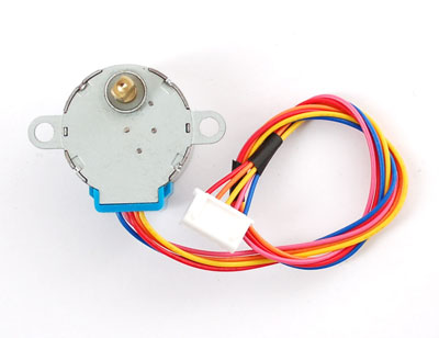
Can-stack steppers are typically smaller and more cheaply made, mounted in a simple can, often with gears on top to increase torque and steps per revolution, and decrease speed. They’re often used in disk drives, motorized lens optics, and other industrial applications. The first number in the spec for these indicates the can’s diameter in millimeters. A 28BYJ-48 motor has a 28mm diameter can. A 24BYJ-48 has a 24mm can size, and so forth. Melissa Zheng has a good explanation of can-stack stepper motor specs.
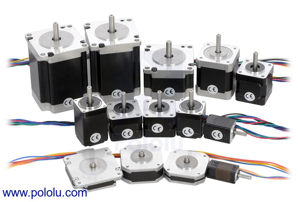
Figure 5 shows a variety of NEMA-style steppers. Figure 6 shows a 28BYJ-48 can-stack stepper.
Figure 5. A range of NEMA stepper motors. Image from Pololu.comFigure 6. a can-stack stepper motor
Control of Stepper Motors
To control the stepper, apply voltage to each of the coils in a specific sequence. Both types of stepper motor can be controlled with a motor driver (related video). The sequence would go like this:
Step
Wire 1
Wire 2
Wire 3
Wire 4
1
high
low
high
low
2
low
high
high
low
3
low
high
low
high
4
high
low
low
high
Table 1. Sequential states of the voltage on the four control pins of a stepper motor.
To step the motor, you change the pins in the order shown in Table 1. With each step, the motor will move forward or backward one increment. Once you have the motor stepping in one direction, stepping in the other direction is a matter of doing the steps in reverse order.
It’s good practice when you wire a stepper up for the first time to write a program to step it slowly, one step at a time, using the steps above. That way you can see if you got the wiring right. If you did, the stepper should turn step by step in one direction. If you didn’t, it may step in unpredictable ways.
A stepper motor’s position is not absolute. You have to know where the motor started (usually measured with an external sensor) and how many degrees per step. Then you count the steps and multiply by that many degrees. So for examples, if you have a 1.8-degree stepper, and it’s turned 200 steps, then it’s turned 1.8 x 200 degrees, or 360 degrees, or one full revolution.
The circuits for controlling a unipolar stepper or a bipolar stepper are very similar. In both cases, you have four ends of coils that go to the four outputs of the driver. The difference is that for the unipolar, you also have a common center wire. That wire can be attached to the same motor voltage supply that feeds the driver, or it can be left disconnected. If you do the latter, you’re treating the unipolar motor as if it had two separate coils — in other words, as if it were a bipolar stepper.
H-bridge Stepper Drivers
There are a couple of different types of stepper motor drivers. The oldest use four transistors, treating each wire as if it were a motor itself. If you take wire 1 high and wire 2 low, coil turns one direction. Take wire 1 low, and wire 2 high, and the coil turns the other direction. The same principle applies to the other coil. This can be done with individual Darlington transistors or MOSFETs, or it can be done with a transistor array like the ULN2004.
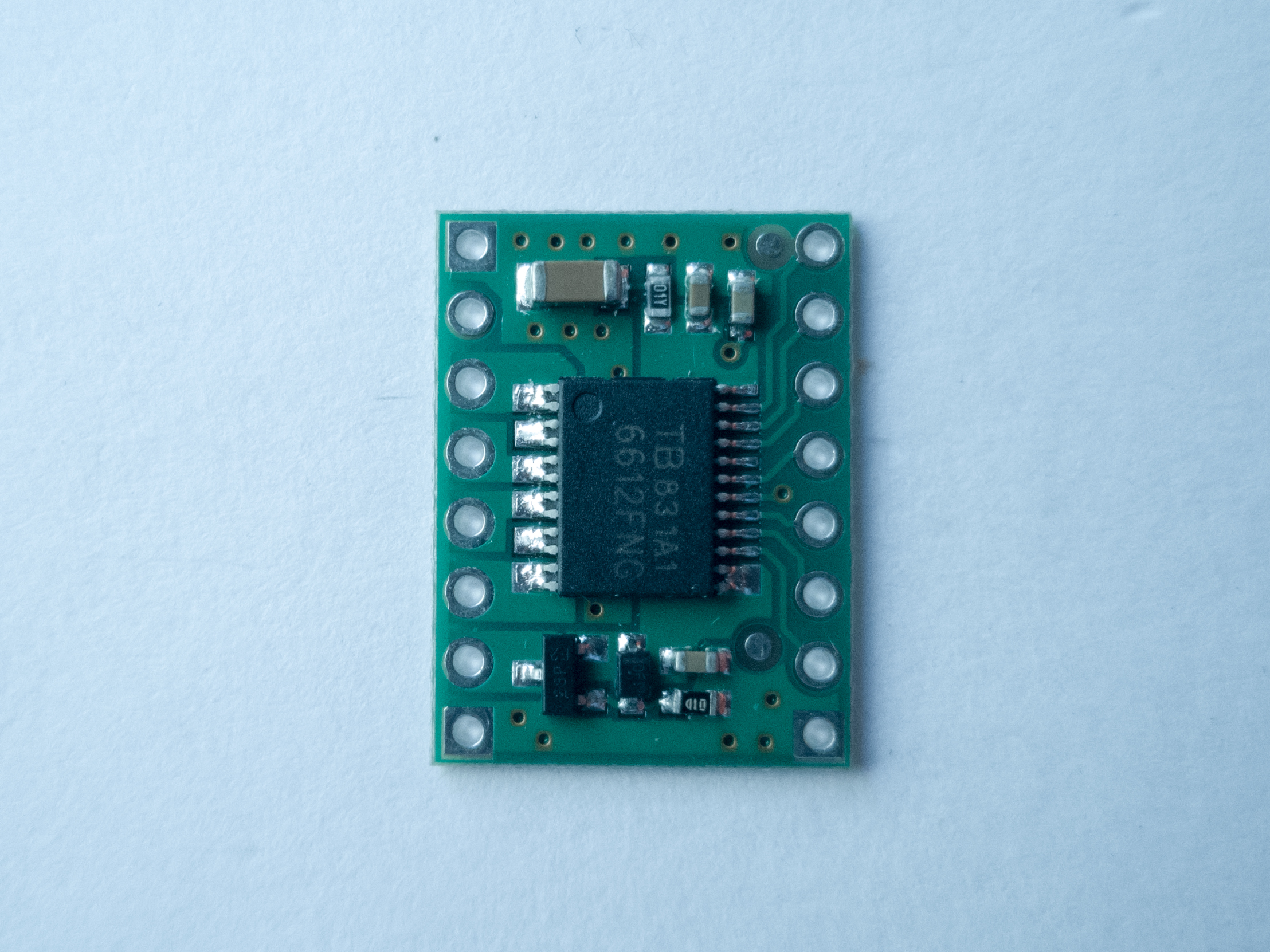
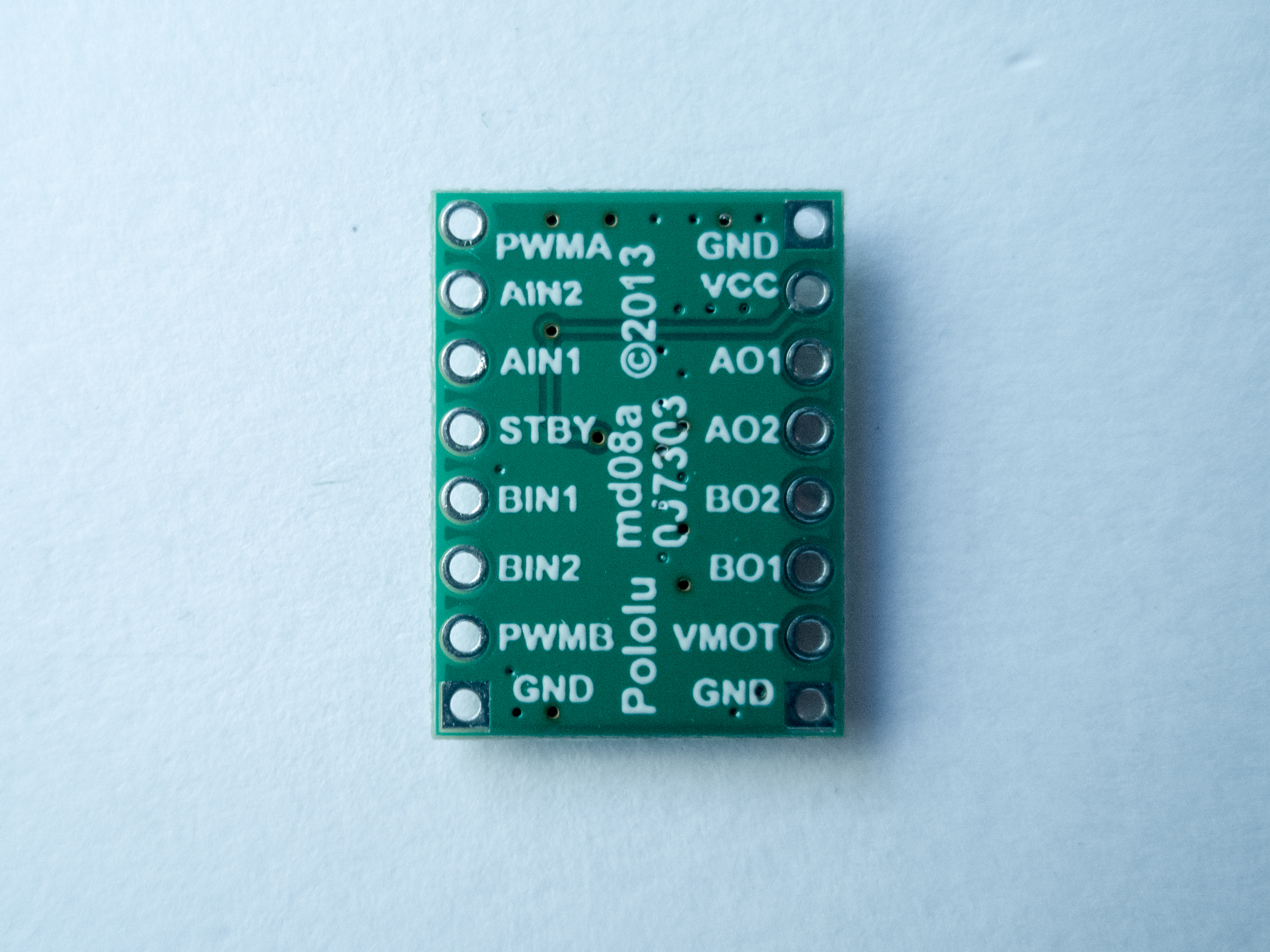
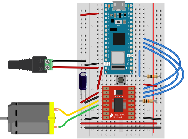
The four-transistor approach is essentially an H-bridge, and you could use two H-bridges to control a stepper. The TB6612FNG dual motor driver that you saw in the H-bridge lab is a dual H-bridge designed for this purpose. You’ll see it in action in the H-bridge stepper motor lab. There is an older H-bridge that only operates on 5V, the L293D, which you will encounter from time to time. This driver does not work with the Arduino Nano 33 IoT and other 3.3V boards, but it’s common enough that it’s useful to know that it can be replaced with a TB6612FNG.
With an H-bridge style driver, you know what you’re getting: take the input 1 HIGH and input 2 LOW, and you create a voltage difference between outputs 1 and 2. It’s conceptually easy, but requires more thinking and planning when you are programming the stepper. Fortunately, there is a Stepper library for Arduino that simplifies this somewhat.
Step & Direction Stepper Drivers
More modern stepper drivers have just two control pins, one for step and one for direction. They also feature configuration pins that let you set the step pin to move the motor a full step, a half step, or less. This is called microstepping, and you can find stepper drivers that will work as low as 1/256th of a step. This allows finer control over the stepper motor.
Step & direction drivers simplify control of a stepper because they only require two signals from a microcontroller: take the direction pin high or low to turn the motor’s direction one way or the other. Then pulse the step pin. With each pulse, the motor should step in the direction set by the direction pin. You can run these kinds of steppers without a library. You’ll see these drivers in the step & direction stepper driver lab.
There are a number of step & direction motor drivers available. For example, ther STSPIN220 from ST microelectronics works in the 1.8-10V range. the A4988 handles motors in the 8-35V range. Trinamic’s drivers, also sold on breakout boards by Watterott as SilentStepStick boards, control a wide range of voltages and are designed to reduce noise. Allegro’s A4988 and Monolithic’s MP6500 and Texas Instruments’ DRV88xx line are also good driver lines to look at. Here’s a comparison chart for many of these lines, on breakout boards from Pololu. Table 2 is a summary of a few other step & direction drivers.
In picking a step & direction driver, the first questions to ask are:
Is my motor’s rated voltage in the driver’s Motor Voltage range?
Is my motor’s rated current less than the driver’s Max. Motor Current range?
Is my microcontroller’s operating voltage in the driver’s Control Voltage range?
Different kinds of computers are designed for different purposes. The computer at the heart of your laptop is optimized for different purposes than the one in your phone or the one in your mouse. The simplest computers are those that are designed to take inout from the physical world and control output devices in the physical world. These are called microcontrollers.
Most electronic devices you use today have a microcontroller at their core. Microcontrollers are optimized for control of physical input and output. They’re generally less computationally capable than the processors used in multimedia computers or servers, for example. They require less power than a those other processors, and they’re easier to interface with the physical world through input circuits called sensors and output circuits called actuators. They can communicate with other processors through various communication interfaces.
Computer, microcontroller, processor? Which is which?
You’ll hear these terms thrown around interchangeably here and in other writing about computers. Computer and processor are generic terms for the anything that can run a program, basically. Controller or microcontroller is usually reserved for a simple processor that does only one task, like listening to sensors. In explaining microcontrollers, we’ll distinguish them from personal computers or servers, which contain more powerful processors that can run an operating system.
Microcontrollers: Computers for the Physical World
When you’re building something that controls digital media from the physical world, it’s common to use microcontrollers to sense the user’s actions, then pass information about those actions to a multimedia processor like the one in your laptop. Keyboards and computer mice have microcontrollers inside that communicate with personal computers using the USB communications protocol.
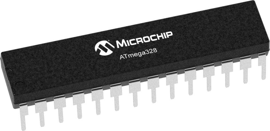
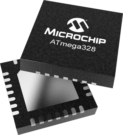
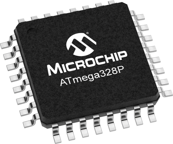
Figure 1. Atmel Atmega328P chipFigure 2. Atmel Atmega328P chipFigure 3. SMD package of a microcontroller
Microcontrollers come in many different size packages as shown in Figure 1, Figure 2 and Figure 3.
Like any other computer, a microcontroller has to have input ports to detect action by a user, and output ports through which it expresses the results of its programs. The metal pins or contact points on a microcontroller are the inputs and outputs. Other devices, like light, heat, or motion sensors, motors, lights, our sound devices, are attached to these pins to allow the microcontroller to be sensitive to the world and to express itself. A microcontroller also requires power connections and communications connections, just like any other computer.
Figure 4 shows an Atmel (now owned by Microchip) microcontroller with its pins labelled. You can see which ones are general purpose input and output (GPIO), which ones are for power and communications, and which ones have specialty functions as well, the most common of which is analog input. For more on the typical functions of a microcontroller, see the Microcontroller Pin Functions page.
Figure 4. ATMEGA328 pin diagram
There are several different types of microcontrollers. The simplest have very little program memory, only one or two GPIO pins and no specialty functions. These might only cost a fraction of a dollar apiece in large quantities. Slightly more capable ones will have more memory, more GPIO pins and will include specialty functions as well, such as dedicated pins for particular communications protocols. The Atmega328 processor that’s at the heart of the Arduino Uno is one of these processors. The SAMD21 at the heart of the Nano 33 IoT is its more modern cousin. You can buy these processors for a few dollars apiece in quantity. More powerful than those are the controllers that have connections to interface to a display screen, like those in your mobile phone. These might cost several dollars, or tens of dollars. The more memory, processing power and input/output ports that a microcontroller has, the more expensive it tends to be.
When your device is complex enough to need an operating system, it might contain several controllers and processors. The controls for displays, power, and physical I/O are usually farmed out to microcontrollers, while the central processor runs the operating system, communicating with each lesser processor as needed.
The line between microcontrollers and operating system processors is getting blurry these days, so it helps to understand types of programs that different devices might run in order to understand the difference.
Programs for Microcontrollers and Other Processors
Programs for any processors fall into a few different classes: firmware, bootloaders, basic input-output systems, and operating systems. When you understand how they’re all related, you gain a better picture of how different classes of processors are related as well.
Microcontrollers generally run just one program as long as they are powered. That program is programmed onto the controller from a personal computer using a dedicated hardware programming device. The hardware programmer puts the program on the controller by shifting the instructions onto it one bit at a time, through a set of connections dedicated for this purpose. If you want to change the program, you have to use the programmer again. This is true of any processor, by the way: even the most powerful server or multimedia processor has to have a piece of firmware put on it with a hardware programmer at first.
Microcontrollers generally don’t run operating systems, but they often run bootloaders. A bootloader is a firmware program that lives in a part of the controller’s memory, and can re-program the rest of that memory. If you want to program a microcontroller directly from a personal computer without a separate hardware programmer, or from the internet, then you need a bootloader. Whenever your phone is upgrading its firmware, it’s doing it through a bootloader. Bootloaders allow a processor to accept new programs through more than just the dedicated programming port.
Any processor that runs an operating system will run a Basic Input-Output System, or BIOS as well. A BIOS may be loaded onto a processor using a bootloader. A BIOS runs before, or instead of, the operating system. It can control any display device attached to the processor, and any storage attached (such as a disk drive), and any input device attached as well.
Bootloaders and BIOSes are often called firmware because they’re loaded into the flash memory of the processor itself. See Table 1 for types of firmware. Other programs live on external storage devices like disk drives, and are loaded by the BIOS. These are what we usually think of software. Table 2 shows different kinds of software. When you change a processor’s firmware, you need to stop the firmware from running, upload the new firmware, and reset the processor for the changes to take effect. Similarly, when you change a microcontroller’s program, you stop the program, upload the new one, and reset the microcontroller.
An operating system is a program that manages other programs. The operating system schedules access to the processor to do the tasks that other programs need done, manages network and other forms of communications, communicates with a display processor, and much more.
Programs are compiled into the binary instructions that a processor can read using programs called compilers. A compiler is just one of the many applications that an operating system might run, however. The applications that an operating system runs also live on external storage devices like disk drives.
Firmware
Stored On
Detail
Single Program
Processor’s program memory
Is the only program running; must be loaded by hardware programmer
Bootloader
Processor’s program memory
Must be loaded by hardware programmer; Takes small amount of program memory; can load another program into the rest of program memory
BIOS
Processor’s program memory
Usually loaded by bootloader; can load operating system into RAM memory
Table 1. Types of firmware that are stored directly on a microprocessor
Software
Stored on
Details
Operating System
External mass storage
Runs other programs; loaded into RAM by BIOS; unloaded from RAM on reset
Drivers
External mass storage
Controls access to other processors, like disk drivers, keyboards, mice, screens, speakers, printers, etc. These are usually loaded into RAM on startup of the OS, and controlled by the OS, not the user.
Applications
External mass storage
Loaded into RAM by operating system and unloaded as needed
Table 2. Types of software on an operating system processor, and where they are stored.
Generally, the term microcontroller refers to firmware-only processor, and a processor that runs an operating system from external storage is called an embedded processor, or a central processor if it’s in a device with lots of other processors. For example, the Arduino is a microcontroller. The Raspberry Pi and BeagleBone Black are embedded processors. Your laptop are multi-processor devices running a central processor, a graphics processor, sound processor, and perhaps others.
Microcontroller Development Boards and Activity Boards
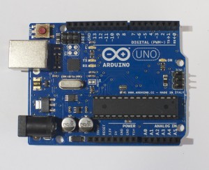
A processor, whether microcontroller or multimedia processor, can’t operate alone. It needs support components. For a microcontoller, you need at least a voltage regulator and usually an external clock called a crystal. You might also add circuitry to protect it in case it’s powered wrong, or in case the wrong voltage and current are plugged into the IO pins. You might include communications interfaces as well. This extra circuitry determines the base cost of a development board like the Arduino (Figure 5) or the Raspberry Pi (Figure 6).
Development boards usually include:
The processor itself
Power regulation circuitry
Hardware programmer connector
Communications interface circuitry
Basic indicator LEDs
Figure 5. An Arduino Uno.Figure 6. A Raspberry Pi
More advanced development boards might also include multiple communications interface circuits, including wireless interfaces; sensors already attached to some of the GPIO pins; a mass storage connector like an SD card; and video or audio circuitry, if the processor supports that. The more features a board offers, the more it costs.
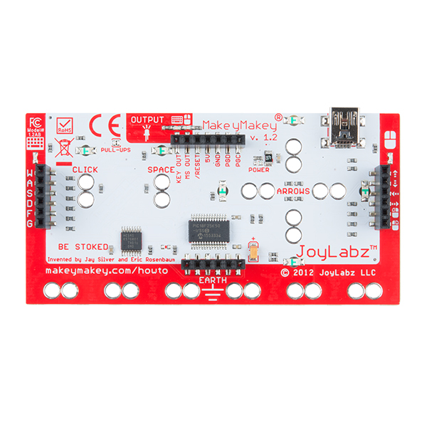
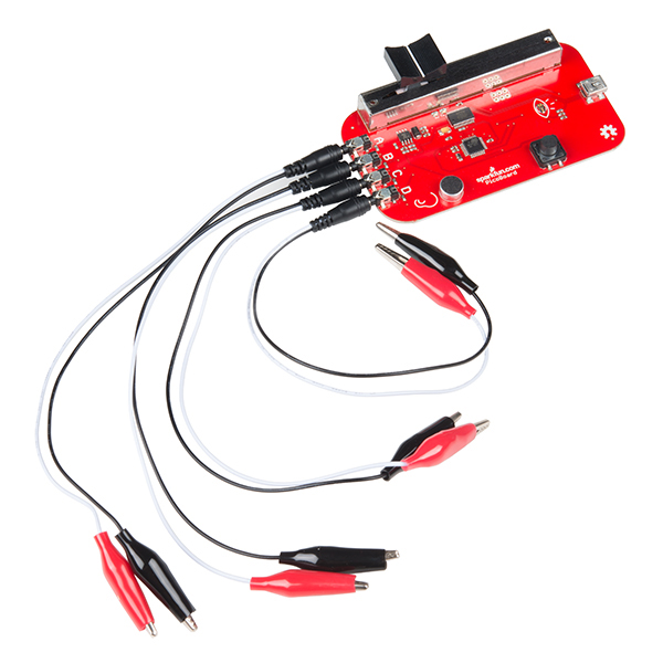
A development board allows you to program the controller’s firmware and software, but an activity board may not. Activity boards contain a pre-programmed microcontroller and some sensors and actuators along with a communications interface and a communications protocol so that you can interface the board and its sensors and actuators with software running on your personal computer. Boards like the MaKey MaKey (Figure 7) or the PicoBoard (Figure 8, now retired) are activity boards. Activity boards generally can’t operate on their own without being connected to a personal computer, while development boards can.
Figure 7. A Makey Makey BoardFigure 8. A Sparkfun Picoboard
Do I Really Need A Development Board?
You can buy and program microcontrollers without a development board or activity board, but you’ll need some extras to do so. First, you’ll need to design your own support circuitry, at least a programmer interface and a power supply. You’ll need a hardware programmer as well, in most cases. And you’ll need to buy breakout boards or learn to make very small surface-mount circuits, since fewer and fewer microcontrollers come in the large dual inline package (DIP) that can plug into a solderless breadboard anymore. Generally, until you are very comfortable with electronics and circuit fabrication, it’s best to start with an activity board or a development board.
Toolchains and Development Environments
The two most common languages for microcontrollers are the assembly language of each particular processor, or the C programming language. More modern processors are starting to be developed in Python as well. A toolchain is the combination of compilers and linkers needed to convert the instructions you write into a binary file that the microcontroller can interpret as its instructions and the programmer software needed to upload that into the processor. Every manufacturer and processor family has its own assembly language (the beginning of the toolchain), but there’s a C compiler for almost every microcontroller on the market. Beyond that, a toolchain might include a compiler or firmware to convert a higher level language into the controller’s assembly language. If it’s a scripted language like Python, then the microcontroller’s firmware might include a Python interpreter that remains on the controller as your various scripts are swapped for one another in development.
A toolchain does the work of converting your code, but an integrated development environment (IDE) is needed to connect you, the programmer, to the toolchain. An IDE usually contains a text editor with user interface elements to send your text to the toolchain and upload the result to the processor. IDEs will also include a display to give you error messages about your code, and a monitor of some sort so that you can see what your code does when it’s running on the processor.
Things to consider when picking a microcontroller:
Here’s a guide to picking a microcontroller for this class. What follows are the economic considerations for picking a microcontroller more generally.
Costs
How much do I want to spend? The more features and flexibility, the higher the cost. But if it reduces the time taken between setting up and expressing yourself, it may be worth spending the extra money.
Time
How much work do I want to do?
An activity board or higher level development board will generally minimize the amount of work you do to build your interface to the world. Lower level dev boards or building your own boards will take more work before you have things working. Don’t go build your own boards unless you have to. Many good projects never get completed on time because the maker wanted to use their project as a way to learn how to make a circuit.
What programming languages/communications protocols/electronics do I already know?
All other things being equal, pick a system whose components you know something about.
What’s the knowledge base like?
Most microcontrollers have several websites and listserves dedicated to their use and programming. Quite often, the best ones are linked right off the manufacturer’s or distributor’s website. Check them out, look at the code samples and application notes. Read a few of the discussion threads. Do a few web searches for the microcontroller environment you’re considering. Is there a lot of collected knowledge available in a form you understand? This is a big factor to consider. Sometimes a particular processor may seem like the greatest thing in the world, but if nobody besides you is using it, you’ll find it much harder to learn.
Expandability/Compatibility
What other components is the microcontroller compatible with?
Can you add on modules to your microcontroller? For example, are their motor controllers compatible with it? Display controllers? Sensors or sensor modules? Often these modules are expensive but they just snap into place without you making any special circuitry. If your time is worth a great deal, then these modules are a good buy. Sometimes even if you know how to build it with a lower level controller, a higher level system is worth the cost because it saves building and maintenance time.
What do I have to connect to?
Are you connecting to a MIDI synthesizer? A DMX-512 lighting board? A desktop computer? The phone system? The Internet? Different microcontrollers will have different interface capabilities. Make sure you can connect everything together. Sometimes this requires some creative combinations of controllers if no one controller can speak to all the devices you want it to speak to.
Physical and Electrical Characteristics
How many inputs/outputs do I need? Every system has a certain number of ins and outs. If you can, decide how many things you want to sense or control before you pick your controller.
What kinds of inputs and outputs do I need? Do you need analog inputs and outputs, for sensing changing values, or do you only need digital ins and outs, for sensing whether something is on or off? Most of the embedded Linux boards (for example, the Raspberry Pi) do not have analog inputs, so be careful of that.
What kind of power is available to me? Does it need to be battery powered? Does it need to match the voltage of another device? Does it need to draw very little amperage?
How fast do I need to process data? Lower level processors will generally give you more speed.
How much memory do I need? If you’re planning some complex data processing or logging, you may need a microprocessor with lots memory, or the ability to interface with external memory.
How small does it need to be? A lower level controller generally lets you build your own circuitry, allowing you to reduce the size of the hardware you need.
The Economics of Microcontroller Development
So where does this leave you, the hobbyist or beginner with microcontrollers? What should you choose?
Using mid-level microcontrollers will cost you relatively little up front, in terms of peripherals. The various components you’ll need to make a typical project will run you about $75 – $100, including the controller. Starter kits are a good investment if you’ve never done it before, as they get you familiar with the basics. If you know your way around a circuit, you can start with just a development board. You can always keep the project intact and re-use the microcontroller for other projects. You’ll save yourself time not having to learn how a hardware programmer works, or which compiler to choose, or how to configure it. For the beginner seeking immediate gratification, mid-level is the way to go. The only downside is that if you want to build many more projects, you’ve got to buy another development board.
Using the controllers by themselves, on the other hand, is more of a hassle up front. You’ve got to know how to build the basic support and communications circuits, how to use a hardware programmer, and how to set up a toolchain. You’ll spend a lot of time early on cursing and wishing you’d bought a development board. The advantage comes a bit later on, once everything’s set up. You’ll eventually save money on development boards, and can make them in any shape you want. It gets better the longer you continue making microcontroller projects. So start with development or activity boards, and move up as your needs demand and knowledge can accommodate.
These notes are heavily indebted to Gordon McComb’s Robot Builder’s Bonanza, second edition, which includes some excellent chapters on motors and motor use.
When trying to move things with microcontrollers, you’re likely to use one of three kinds of motors: DC motors, RC servomotors, and stepper motors. Following is a brief introduction to these three. In order to get the most out of these notes, you should know something about how electricity works, and you should know the basics of how a microcontroller works as well. You should also understand how transistors are used to control high-current loads.
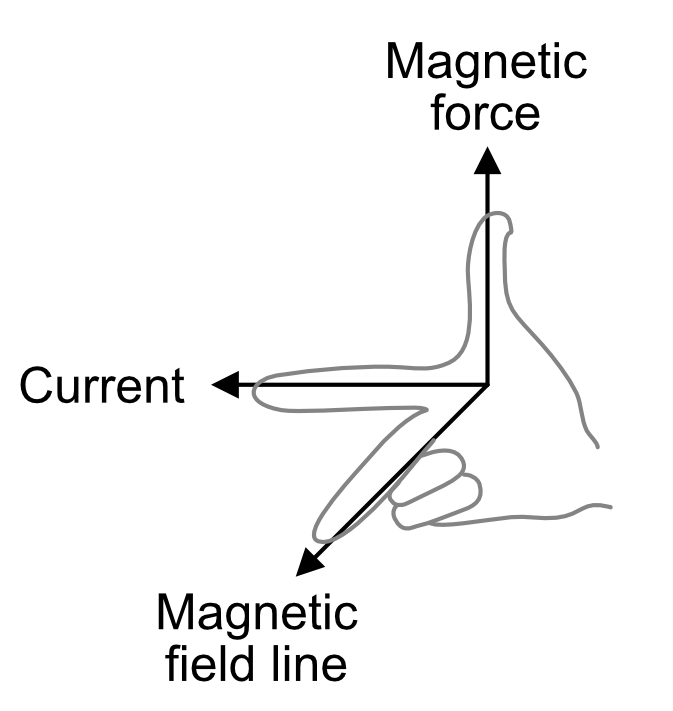
Motors convert electrical energy into mechanical energy so that you can move things in the physical world. They are based on the electrical principle of induction. When you put electric current through a wire, it generates a magnetic field around the wire as shown in Figure 1. The direction of the magnetic field is related to the direction of the electrical current. It’s often described as the right-hand rule. If you hold your right hand up and put your thumb perpendicular to your index finger, then put your middle finger perpendicular on the other axis, can see the directions of current flow (your index finger); magnetic force (your thumb); and the magnetic field line (your middle finger). The higher the current, the greater the magnetic field, and therefore the greater the attraction or repulsion.
Figure 1. The relationship between current, magnetic force, and magnetic field direction.
Similarly, if there’s a magnet near a wire, its field will interact with the wire’s magnetic field and generate a current in the wire. If you mount magnets on a spinning shaft surrounded by the wire, you have a motor. In Figure 2, the wire is arranged in two coils. As the magnets are alternately attracted to one coil and repulsed by the other, it spins from one to the other, and you get circular motion. Figure 2 illustrates the basic mechanism of a DC motor.
Figure 2. The basic mechanism of a DC motor.
All inductive loads (like motors, electromagnets, and solenoids) work on this same principle: induce a magnetic field by putting current through a wire, use it to attract or repulse a magnetic body. However, the principle works in reverse as well. When you spin a wire in an existing magnetic field, the field induces a current in the wire. So if you’ve got a motor spinning, and you turn it off, the fact that the motor’s coil is spinning in a magnetic field will generate a current in the wire while it’s spinning. You can test this by attaching an LED to the two leads of a DC motor and spinning the motor by hand. Spun in one direction, the LED will light. Spin in the other, the LED won’t light.
This generated current comes back in the reverse direction of the current flow you generated to run the motor. When the motor isn’t attached to another source of electricity, you’d call this a generator as in the LED experiment, because the motor is now generating voltage. When the motor is connected to another power source, it’s called back voltage, and it can cause damage to your electronics. Usually it’s stopped by putting a diode in parallel with your motor to route the back voltage through the diode.
Motor Characteristics
There are a few characteristics common to all motors that you should keep in mind when looking for motors:
Voltage
The rated voltage of a motor is the voltage at which it operates at peak efficiency. Most DC motors can be operated somewhat above or below their range, but it’s best to plan to operate them at their rated voltage. Dropping below rated voltage reduces the motor’s power, and operating above the rated voltage may burn the motor out. Plan on the motor’s top speed being at rated voltage, and slowest speed at no more than 50% less than the rated voltage.
Current
Motors draw current depending on the load they’re pulling. Usually more load means more current. Every motor has a stall current, which is the current it draws when it’s stopped by an opposing force. This stall current is generally much greater than the running current, or current that the motor draws under no load. Your power supply for a motor should be able to supply the stall current with extra amperage to spare. Motors will draw the stall current for a brief period of time when starting up, to overcome their inertia.
Speed
Motor speed is given in revolutions per minute (RPMs). At the rated voltage, your motor should be turning at the rated speed.
Torque
Torque is the measure of a motor’s turning force. It’s the force a motor can pull when the opposing force is attached to a shaft attached to its center rod. If the shaft sticks out a foot from the motor’s center, and the motor can pull one pound on that shaft, the motor’s torque is one foot-pound. Figure 3 illustrates this with a motor that supplies 1g*cm. Related video: Torque and Gearboxes
Figure 3. Torque illustrated. This motor can lift a 1 gram weight at a distance of 1 centimeter out from the center of rotation. Therefore, it can supply 1g*cm of torque.
Resistance
Often you’ll see a motor rated in ohms. This just gives you the resistance that the motor’s coil offers. Using Ohm’s Law (voltage = current x resistance), you can calculate the motor’s current draw if you know the rated voltage and the coil resistance.
Types of Motors
DC Motor
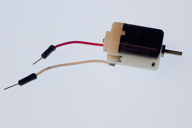
The DC Motor is the simplest of the motors discussed here. Figure 4 shows a photo of a small DC motor. It works on exactly the principle discussed above. There are two terminals, and when you apply direct current to one terminal and ground the other, the motor spins in one direction. When you apply current to the other terminal and ground the first terminal, the motor spins in the opposite direction. By switching the polarity of the terminals, you reverse the direction of the motor. By varying the current supplied to the motor, you vary the speed of the motor. Specific techniques for doing these tasks are discussed below. Related video: Power to a DC Motor
DC motors are usually very fast, often spinning at several thousand revolutions per minute (RPM). The DC motor in Figure 4 is common to many toy and hobby projects.
Figure 4. Small DC motor, 130 size
For more on DC motor control, see this lab for single-direction control, or this lab for controlling a motor in two directions with an H-Bridge.
Gearhead Motor
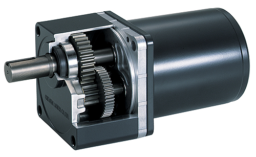
Gearhead motors are a subset of DC motors. Figure 7 is a drawing of a gearhead motor. They have a box on the top of the motors containing a series of gears that slow the rotational speed of the motor down and increase the torque. They are useful when you don’t need a lot of speed, but you do need power. They are controlled exactly the same as regular DC motors.
Figure 7. Gearhead motor with the gears shown. Image from designworldonline
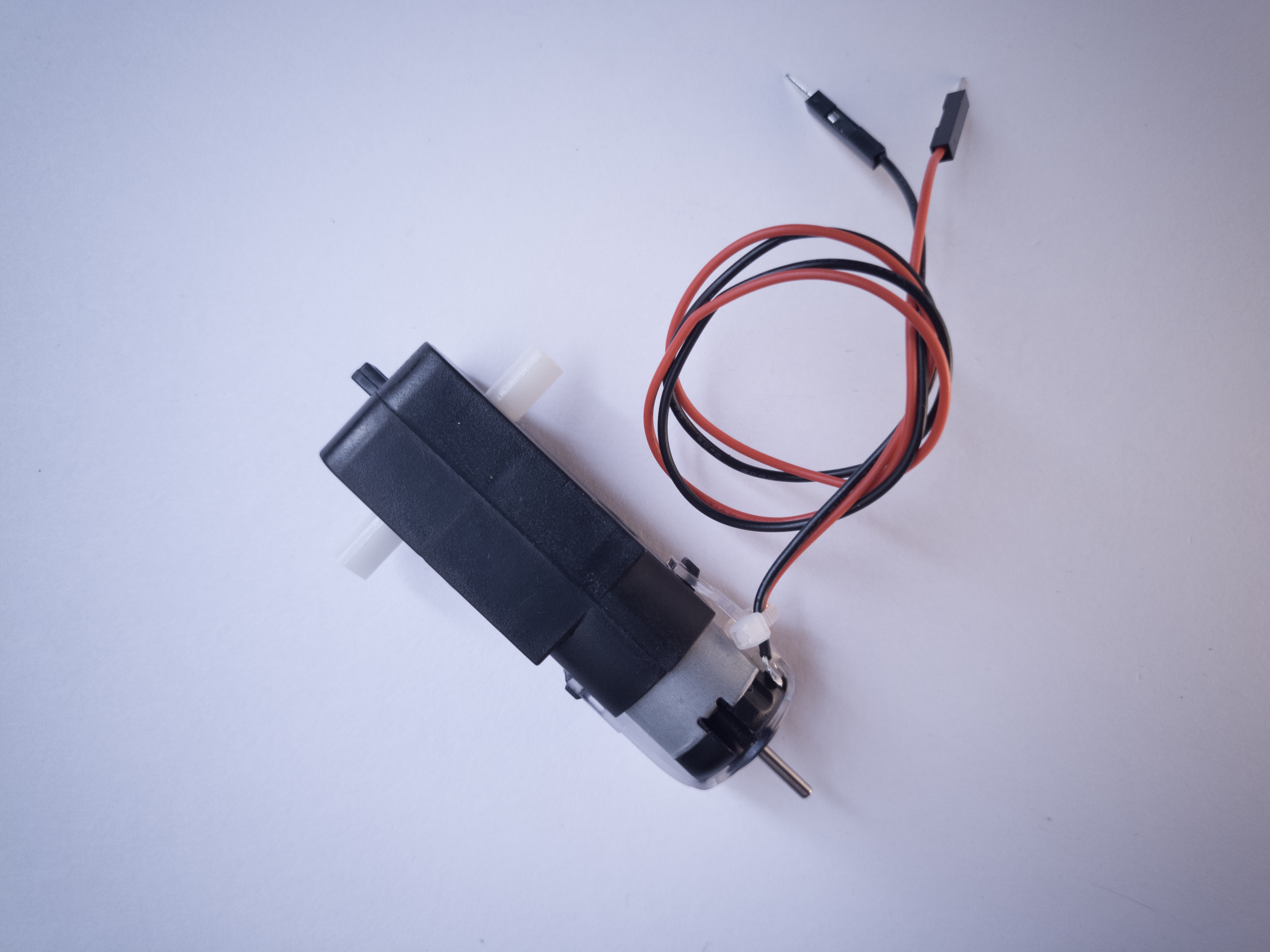
In Figure 8, you can see a gearmotor that uses this size motor. You can see the full specifications at this link. Table 1 has a summary of the specs. You can see that the no-load current is 190mA and the stall current is 250mA. and the rated voltage is 6V. Using this information, you could work out that the coil resistance is probably between 24 and 32 ohms. You can also see that the no-load speed is 230RPM and the stall torque is 0.8 kg-cm. These are the values for the motor with the gearbox attached.
Figure 8. DC Gearmotor
Voltage (Nominal)
6VDC
No-Load Speed @ 6VDC
230RPM
No-Load Current @ 6VDC
190mA
Stall Current @ 6VDC
250mA
Stall Torque @ 6VDC
11.11 oz-in (0.8 kg-cm)
Gear Ratio
48:1
Table 1. Abbreviated specs on a gearmotor.
DC Motor Control
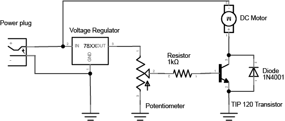
There are two easily controllable parameters of a DC motor, direction and speed. To control the direction, you reverse the direction of the voltage through the motor. To control the speed, you pulse width modulate it.
Direction
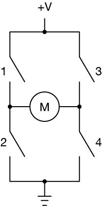
To control a DC motor from a microcontroller, you use switching arrangement known as an H-bridge, consisting of four switches with the motor in the center. Figure 9 is the schematic for a typical H-bridge:
Figure 9. An H-bridge, at its simplest, is composed of four switches with a load at the center of them.
When switches 1 and 4 are closed and 2 and 3 are open, voltage flows from the supply to 1 to the motor to 4 to ground. When 2 and 3 are closed and 1 and 4 are open, polarity is reversed, and voltage flows from the supply to 3 to the motor to 2 to ground. Related video: H-Bridge
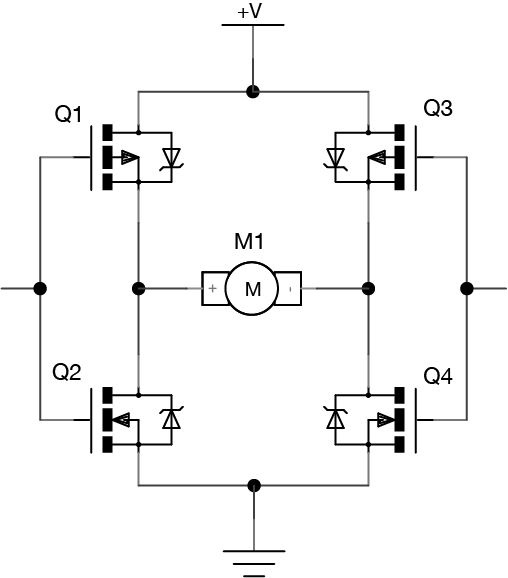
An H-bridge can be built from transistors, so that a microcontroller can switch the motor, like this in Figure 10:
Figure 10. An H-bridge made of transistors.
This schematic uses MOSFETs, which are good for controlling motors. The top two transistors above are P-channel, meaning that they allow current to pass when the gate voltage is low rather than high. The bottom two are N-channel, so that the proper two transistors always switch together. When the left control pin is high, transistor 1 (labeled Q1) turns off because it’s a P-channel and Q2 turns on because it’s an N-channel. The same happens with Q3 and Q4. If you were using this circuit, you’d want to make sure that the control pins are always reversed; when one is high, the other is low. Related video: MOSFET Transistor
Although you can make your own H-bridges, it’s usually easier to use a controller manufactured specifically for the job. A pre-manufactured H-bridge chip will include diodes to protect the transistors from back voltage, sometimes a current sensing pin to sense the current the motor is drawing, and much more. There are many motor drivers available from various electronics suppliers. Look around to find one that suits your needs and price range.
Speed
A DC motor’s speed is proportional to the supplied voltage. If the voltage drops too far, the motor won’t get enough power to turn, but within a certain range, usually 50% of the rated voltage, the motor will run at varying speeds. The most effective way to adjust the speed is by using pulsewidth modulation. This means that you pulse the motor on and off at varying rates, to simulate a voltage. Related video: Why use PWM on DC Motors?
RC Servomotor
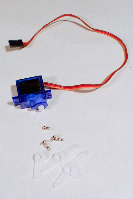
Servo motors are a variation on the gearhead motor coupled with a potentiometer to give feedback on the motor’s position. Figure 11 shows a photo of a small servomotor. The gears of the gearbox on a servo are attached to a potentiometer inside the case, and the pot is turned by the turning of the motor. The pot is connected to a capacitor in a resistor-capacitor circuit (R-C), and by pulsing this R-C circuit, you give the motor power to turn. When the motor turns, it changes the resistance of the R-C circuit, which in turn feeds the motor again. By pulsing the R-C circuit, you set the motor’s position in a range from 0 to 180 degrees. Related video: Meet the motors – servomotor
Figure 11. a small RC Servomotor
Servos have three wires to them, unlike most DC and gearhead motors, which have two. The first two in a servo are power and ground, and the third is a digital control line. This third line is used to set the position of a servo. Unlike other DC motors, you do not have to reverse the polarity of a servo’s power connections to reverse its direction.
Hobby servos, the kind most often used in small physical computing projects, usually take a pulse of between 1-2 ms every 18-20 ms. They rotate 0 to 180 degrees depending on the pulsewidth. A pulse of 1 ms will turn the motor to 0 degrees; 2 ms will turn it to 180 degrees. A servo needs to see a pulse every 18-20 ms even when it is not turning, to keep it in its current position, so once you’ve moved the motor to a new position, it’s essential to keep pulsing it with the same pulsewidth to keep it there.
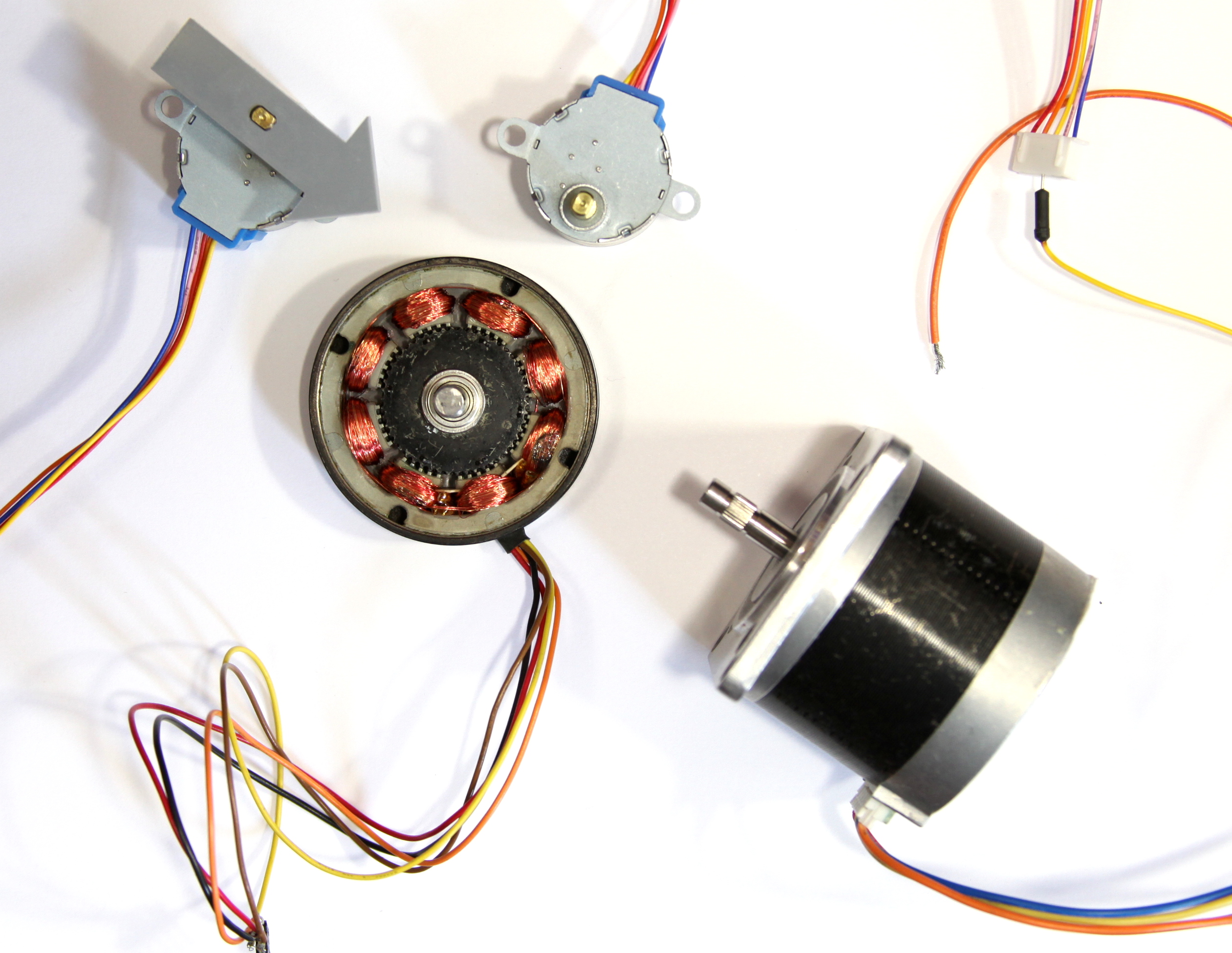
Stepper motors are different than regular DC motors in that they don’t turn continuously, but move in a series of steps. A stepper motor is a motor that has multiple coils, not just one. By energizing each coil in sequence, you attract the shaft magnets to each coil in the sequence, and you can turn the motor in precise steps, rather than simply rotating continually. Figure 12 shows photos of stepper motors in varying sizes.
Figure 12. Stepper motors
This design allows for very precise control of the motor: by proper pulsing, it can be turned in very accurate steps of set degree increments (for example, two-degree increments, half-degree increments, etc.). They are used in printers, disk drives, and other devices where precise positioning of the motor is necessary. Steppers usually move much slower than DC motors, since there is an upper limit to how fast you can step them (5-600 pulses per second, typically. However, unlike DC motors, steppers often provide more torque at lower speeds. They can be very useful for moving a precise distance. Furthermore, stepper motors have very high torque when stopped, since the motor windings are holding the motor in place like a brake.
To control a stepper, you use stepper driver that will energize the coils in the right order to make the motor move forward. There are plenty of libraries and driver modules and ICs that simplify the process. What follows is a low-level explanation of how steppers work.
Stepper Motor Control
There are two types of stepper motors, called unipolar and bipolar. The difference is in their wiring. Unipolar steppers have all of their coils joined by a center wire. Bipolar steppers have two coils, which are not joined. Unipolar motors typically have five wires, while bipolars have four or six wires. Unipolar stepper motor’s wiring works as shown in Figure 13:
Figure 13. The wiring for unipolar stepper motors. The center wires for the two coils are tied together in a unipolar stepper.
The extra two wires in a 6-wire bipolar stepper allow you to use it as a 4-coil motor instead of a 2-coil, by using the center wire on each coil as a common supply or ground. In addition, you can turn a 6-wire bipolar into a 5-wire unipolar by joining the two center wires as shown in Figure 14:
Figure 14. Wiring for bipolar stepper motors.
To determine which wire is which, measure the resistance of the coils. In a bipolar motor, the two coils will have the same resistance, and they are not connected to each other. So if you see infinite resistance, you have two wires on separate coils. When you find two pairs that have the same resistance, you’ve found the two coils of your bipolar stepper. In a six-wire bipolar motor, the resistance between the outside wires of a coil will be twice what it is between the center wire and either outer wire. In a unipolar stepper, the resistance between the center wire and any of the other four will be the same, and the resistance between any two outer wires will be twice what it is from the center wire to any of the outer wires, as shown in Figure 15 and Figure 16:
Figure 15. Schematic drawing of a unipolar stepper motor. If the resistance between 5 and any of the others is X ohms, then the resistance between any of the other pairs (e.g. 2 to 4, 3 to 4, etc.) is 2X ohms.
Figure 16. Schematic drawing for two bipolar stepper motors. In both cases, if the resistance between the ends of either coils is X ohms, then the resistance between either end and the middle of a coil is 0.5X ohms.
Like other motors, the stepper requires more power than a microcontroller can give it, so you’ll need a separate power supply for it. Ideally you’ll know the voltage from the manufacturer, but if not, get a variable DC power supply, apply the minimum voltage that the supply can generate voltage across two wires of a coil (e.g. 1 to 2 or 3 to 4) and slowly raise the voltage until the motor is difficult to turn. It is possible to damage a motor this way, so don’t go too far. Typical voltages for a stepper might be 5V, 9V, 12V, 24V. Higher than 24V is less common, and frankly, above that it’s best not to guess. Related video: Connect 12V Power Supply
To power each coil, you supply voltage one side of the coil while grounding the other side. Typically, you drive a stepper motor with an H-bridge or an array of power transistors or MOSFETS.
To move the stepper, you apply voltage to each of the coils in a specific sequence. Typical phasing could go as shown in Table 2
Step
Wire 1
Wire 2
Wire 3
Wire 4
1
high
low
high
low
2
low
high
high
low
3
low
high
low
high
4
high
low
low
high
Table 2. Stepper motor wire stepping sequence
Once you have the motor stepping in one direction, stepping in the other direction is simply a matter of doing the steps in reverse order. Knowing the position is a matter of knowing how many degrees per step, and counting the steps and multiplying by that many degrees. So for examples, if you have a 2-degree stepper, and it’s turned 180 steps, then it’s turned 2 x 180 degrees, or 360 degrees, or one full revolution.
This lab will introduce you to a few basic electronic principles by trying them in action. You’ll learn how to measure voltage, amperage, and resistance using a multimeter. You will also learn about components in series vs. parallel and be introduced to Ohm’s Law in practice.
Introduction
This lab will introduce you to a few basic electronic principles by trying them in action. You’ll learn how to measure voltage, amperage, and resistance using a multimeter. You will also learn about components in series vs. parallel and be introduced to Ohm’s Law in practice. For more information on the theory behind this lab, please check out these notes.
When you’re building electronics, you run into problems all the time. Diagnosing those problems relies not only on a good theoretical knowledge of how circuits work, but also on practical knowledge of how to test them. The most common tool for testing circuits is the multimeter, a device that can measure current, voltage, resistance, and electrical continuity. More expensive multimeters can also measure other electrical properties, but if you can measure these four, you can diagnose most common circuit problems.
What You’ll Need to Know
To get the most out of this lab, you should be familiar with the following concepts beforehand. If you’re not, review the links below:
Before you get started, you will want to make sure your meter is working. This is a particularly good idea if you’re using a meter that lots of other people use, such as the ones at ITP. Here is how to test that:
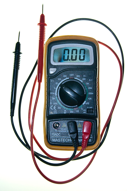
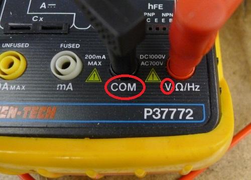
Insert the two probes. Insert the Black probe in the “COM” jack. This is the COMmon, or ground, connection. The Red probe should be in the “V” jack (Figure 11). This connection is for measuring voltage. It can also be used to measure resistance in Ohms, or frequency in megaHertz, on the meter shown here.
Figure 11. Multimeter detail, showing the holes for the probes.
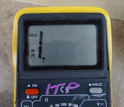
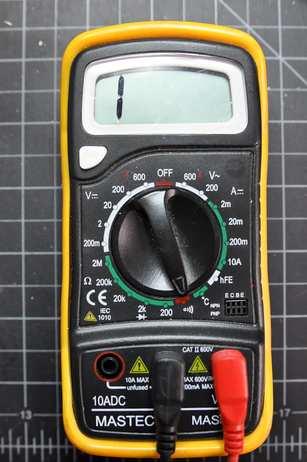
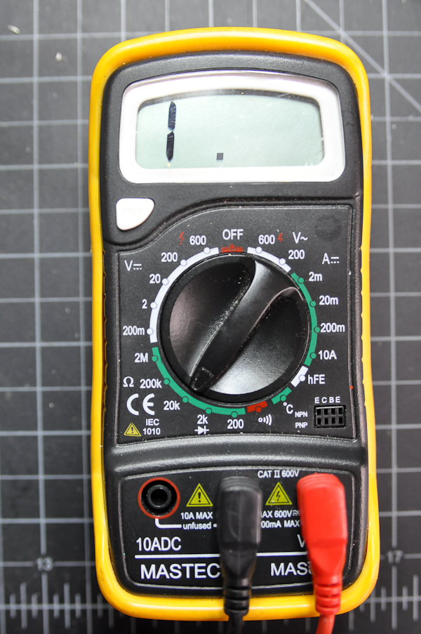
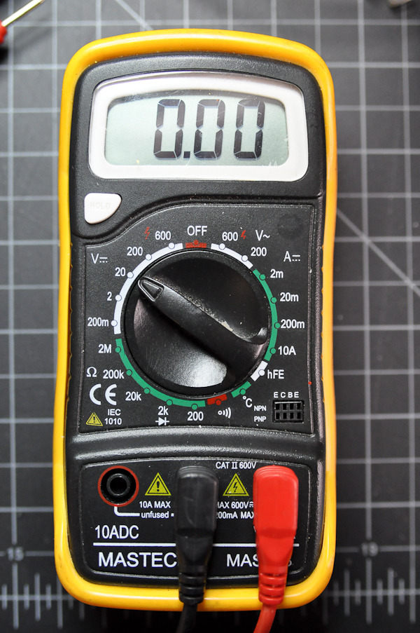
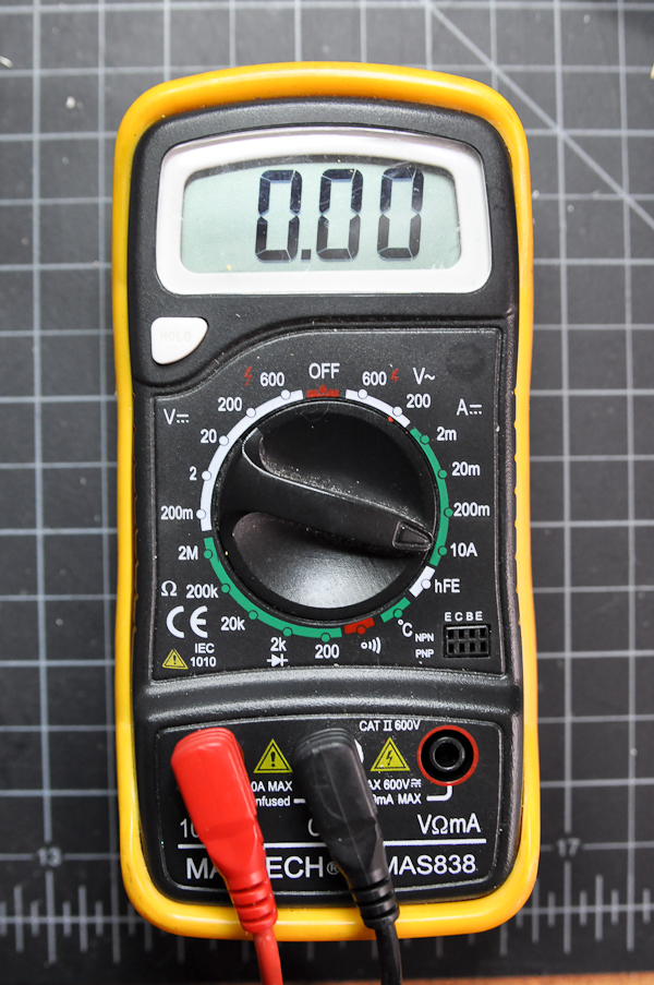
Turn the function knob to the Diode/Continuity Function and switch the meter on. If the word “Hold” appears on the screen, press the hold button once to disable the hold function (not all meters have a clearly labeled Hold function; check your meter’s manual to be sure – see Figure 12). This function is used to hold a value onscreen after you remove the probes from a circuit. The “1.” on left picture means the value is out of range now.
Figure 12. This multimeter’s hold button is on the right side below the screen.
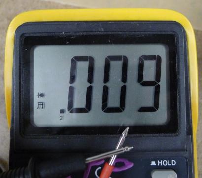
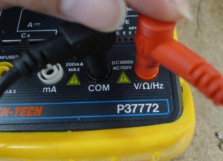
Touch the tips of the probes together. The meter will beep and the display value should be less than 0.01 (Figure 13). If it works, congratulations! you have a usable meter. If not, try to push the plug of the probes to improve the contacts (Figure 14). In many cases the failure is caused by loose contact of the jacks. In other cases, you might have a weak or dead battery.
Figure 13. Detail of .a meter measuring continuity. The meter is should be making a beeping sound in this case.
Figure 14. If the meter is not working correctly, check to see if the probes are plugged in properly.
The Controls on a Meter
Different meters have different controls, but most meters will have the following:
Voltage: This setting is generally broken up into Volts DC, indicating that the polarity of the voltage will not change, and Volts AC, indicating that the polarity will alternate.
Amperage: This setting measures the current in a circuit. Again, it’s usually broken up into AC and DC. There are commonly two holes for the positive probe to measure current, one that’s low amperage and the other that’s high amperage. Don’t try to measure high amperages with the positive probe in the low amperage hole or you will damage the meter.
Resistance: Resistance is measured in ohms. This function is sometimes grouped with the continuity check.
Continuity: Continuity measures for a connection, generally very low or no resistance.
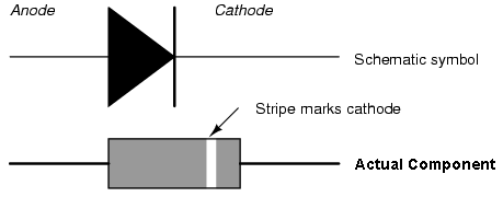
Diode Check: Diode check measures for a voltage drop across a diode, typically 2.7V or less. If you hold the positive probe on the anode of the diode and the common probe on the cathode, you’ll see a voltage drop. If you reverse the probes, you’ll see no reading.
Some meters are auto-ranging, meaning that they will choose the right order of magnitude for a reading automatically. These meters will only have one setting for a given property (volts, ohms, amps, etc). Other meters are not auto-ranging. These meters will have multiple settings for a given property. For example, the meter in the next section below has multiple settings for the resistance (or ohms) property: 2M (megohms), 200k (kilohms), 20k, 2k, and 200 ohms.
Many meters will have additional functions, like temperature, capacitance, transistor checks, and more. The functions listed above are the minimum that you can expect, however.
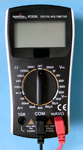
Figures 15 and 16 show two multimeters. Figure 16 is autoranging and Figure 15 is not. Notice how the autoranging meter has only one setting per function, while the non-autoranging meter has several per function. For example, Voltage on the meter in Figure 15 is divided into AC (marked by a ~) and DC (marked by a ⎓). Within those two areas, there are multiple possible ranges: DC voltage can be set to 200mV, 2V, 20V, 200V, or 6ooV. Each range setting represents the maximum voltage you can read on that setting.
Figure 15. A non-autoranging multimeter. Each function has multiple possible range settings.
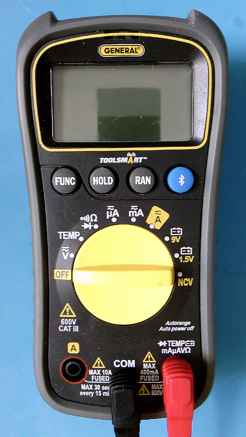
Figure 16. An autoranging multimeter. It has only one setting for each function and the meter automatically detects the range.
The Symbols on a Meter
Here are a few of the common symbols on electrical meters:
Volts: V
Ohms (resistance): Ω
Amps (current): A
AC: ~, ⏦ (tilde, sine wave)
DC: ⎓
Continuity: diode, speaker
Diode Check:diode
Non-Contact Voltage: NCV
Ground: ⏚ (vertical line with three horizontal lines below it)
Measuring Continuity
Continuity is simply whether or not there is a connection between two points. You just used this function to test your meter (Figure 17). Now you’ll use it to test a conductor.
Figure 17. This meter is ready to do a continuity check. The screen reads 1 on the right hand side. For this meter, this indicates that there is no continuity at the moment.
You can use the continuity check to find connections on a switch or if the pushbutton is connected when you press the button. You can also use it to measure whether there’s a break in a wire, or whether a given material conducts electricity. Set your meter as shown here, and try touching the probes together. The meter should beep.
Now try touching the probes to two ends of a wire. Again, the meter should beep. The wire conducts electricity. There is a continuous flow of electricity from one end of the wire to another.
Touching Two Points on a Switch
If you touch two points on a switch, what happens when you switch the switch? Beep or no beep? When you close the switch, the meter should beep, indicating that there is continuity between the two probes of the meter. If the meter beeps whether the switch is open or closed, then those two points are always connected.
Probing Points on a Breadboard
Put a wire in one hole of a breadboard that has no circuit on it. Then put another wire in another hole, chosen at random. Measure continuity between the two wires. Did you get what you expected? If the two holes were in the same row (or in the same column, on the side of the board) then you would get continuity and the meter would beep. If they were in different rows, then it would not beep.
Measuring Continuity Across Your Hand
Try measuring the continuity across your hand. Do you get anything? Why or why not? You probably don’t because the resistance across your skin is so high that it doesn’t register as a continuous conductor. It can conduct small amounts of current though. You don’t want your body to carry high amounts of current or voltage though, because it can damage or kill you.
Setup the Breadboard
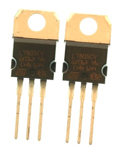
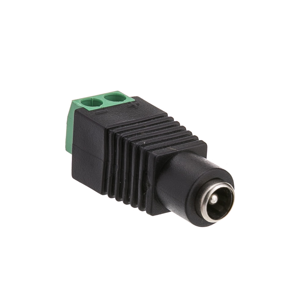
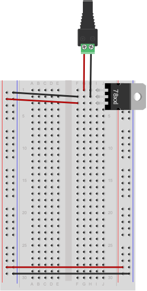
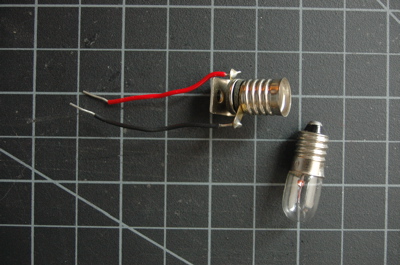
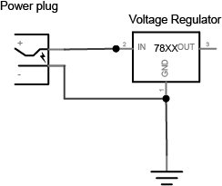
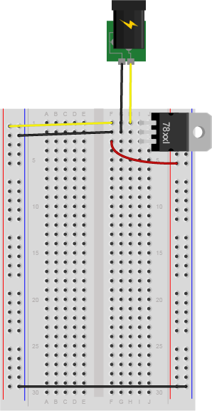
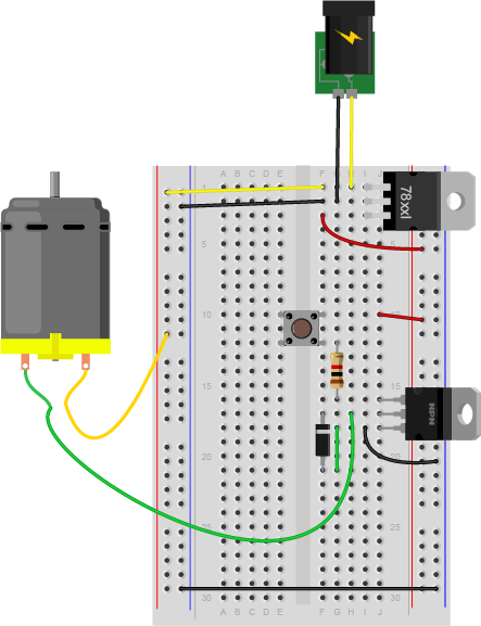
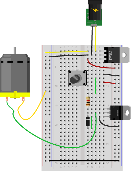
For the rest of this lab, you’ll need a breadboard connected to a +5 Volt or +3.3 volt power supply. You can use an Arduino as your power supply (Using Arduino Uno shown in Figure 18, using Arduino Nano shown in Figure 20), if it’s connected to a USB power supply or a DC power supply, or you can solder together a DC power jack as shown in the Soldering lab, and use a 9-12V DC power supply and a 7805 voltage regulator (Figure 19). The voltage regulator will take the DC power supply’s Voltage and regulate it down to 5 Volts DC.
If you are using a Nano for the first time, you might want to check out these videos before you get started, to prep your board and care for your microcontroller.
Note: Schematics
The diagrams to the left of some of the breadboard images in this exercise are called schematics.They show the electrical layout (as opposed to the physical layout) of the components. For a good rundown on reading and understanding schematics, see this page and some very useful videos on this topic in the videos section of this site.
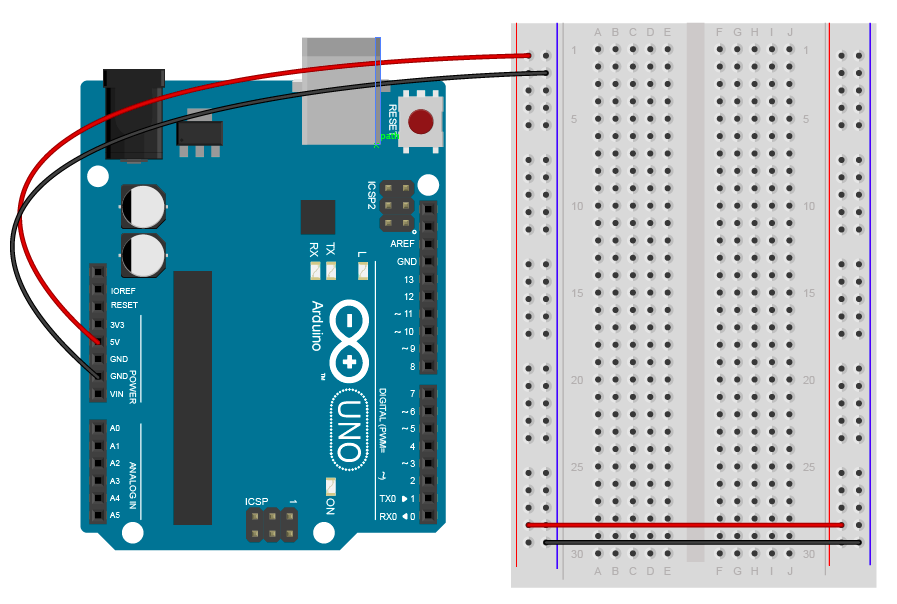
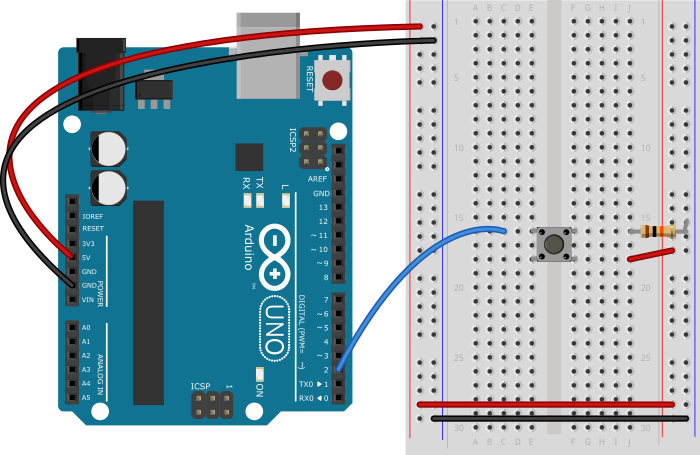
Figure 18. An Arduino Uno connected to a breadboard. The Arduino’s 5V and ground holes are supplying voltage to the breadboard.
Figure 19. DC voltage jack and 7805 voltage regulator on a breadboard. The regulator is supplying 5V and ground holes are supplying voltage to the rest of breadboard.
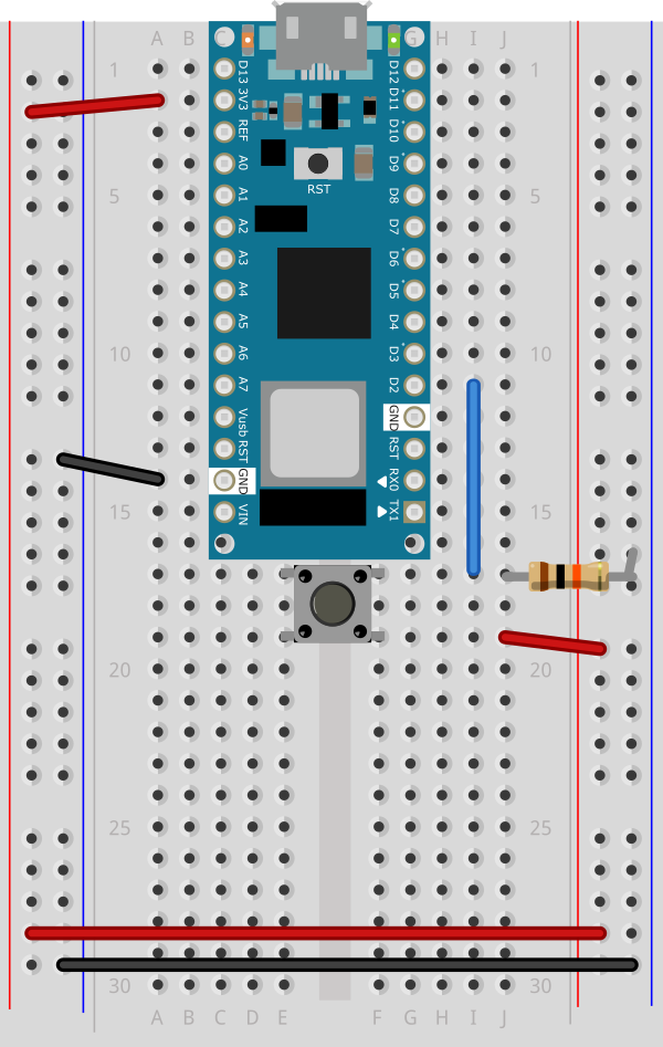
Figure 20. Breadboard view of an Arduino Nano connected to a breadboard.When plugged into a USB port, this board will supply 3.3V across the voltage and ground buses. The +3.3 volts and ground pins of the Arduino are connected by red and black wires, respectively, to the left side rows of the breadboard. +3.3 volts is connected to the left outer side row (the voltage bus) and ground is connected to the left inner side row (the ground bus). The side rows on the left are connected to the side rows on the right using red and black wires, respectively, creating a voltage bus and a ground bus on both sides of the board.
From here on out, diagrams will show the DC power supply and voltage regulator version, but feel free to use the Arduino version instead if you prefer.
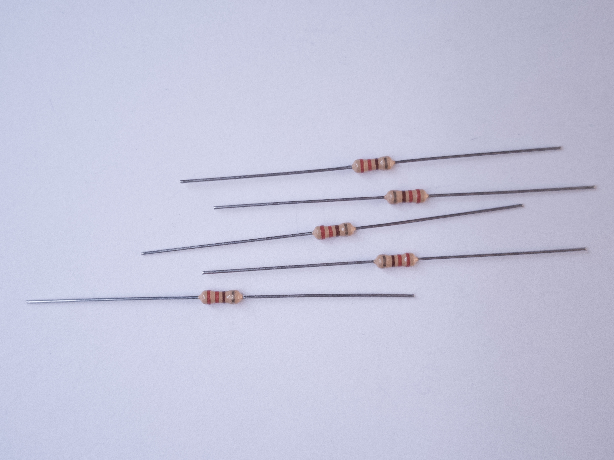
Measuring Resistance of a Component
Resistance is a material property of any component, like a resistor or a wire. To measure the resistance of a component, you have to remove the component from the circuit. To measure resistance, turn your meter to the setting marked with the Greek letter Omega (Ω), as shown in Figure 21.
Figure 21. Multimeter set to measure resistance.
If your meter is not an auto-ranging meter, you want the meter set to the approximate range, and slightly higher than, of the component’s resistance. For example, to measure a 10-Kilohm resistance, you’d choose 20K, because 10K and 20K are in the same order of magnitude. For a 50K resistance, or anything over 20K, you’d have to step up to 200K. If you don’t know the component’s resistance, start with the meter set to a high reading, like 2M (2 Megohms). If you get a reading of zero, turn the meter one step lower, and keep doing so until you get a good reading. A reading of 1 on the left side of the meter, or of 0L, indicates you’re set to too low a range.
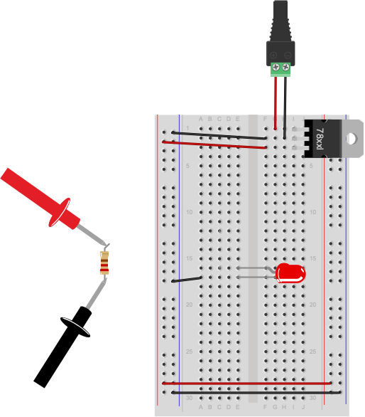
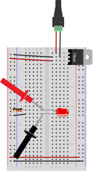
Figure 22. Measuring resistance. Note that this circuit is not complete. To measure a component’s resistance, you have to take it out of the circuit.
Not all components will register resistance. For example, a wire will ideally register 0 Ohms, because you want wires to have as little resistance as possible so they don’t affect the circuit. The longer the wire, the greater the resistance, however. Likewise, switches have ideally zero resistance.
The circuit shown in Figure 22 is not complete. The resistor connecting the LED to voltage has been removed to measure its resistance. The resistor would normally connect in the row connecting to the red wire (row 12) to the anode of the LED (row 15). To measure resistance of a component, you must remove it from the circuit.
Resistance and Diodes
If you measure the resistance of a diode (such as the LED shown in Figure 20), you may see a number flash briefly on the meter, then disappear. This is because diodes ideally have little or no resistance once voltage is flowing through them, but have what’s called a forward bias,which is a minimum voltage needed to get current flowing. Before you reach the forward bias voltage, the diode’s resistance is ideally infinite. After you reach it, the resistance is ideally zero. There are no ideals in electronics, however, which is why you see a resistance value flash briefly as the meter meets the diode’s forward bias. Most meters have a diode check setting, marked with a diode symbol, that will allow you to check the forward bias of the diode.
Try measuring the resistance across your hand. Set the meter really high, perhaps 20 Megohms. Do you get anything? You should get a resistance in the 2-20 Megohm range. Make your palm sweaty, or lick it, and try again. You should get a lower resistance, perhaps 0.2 Megohms or so.
Measuring Voltage
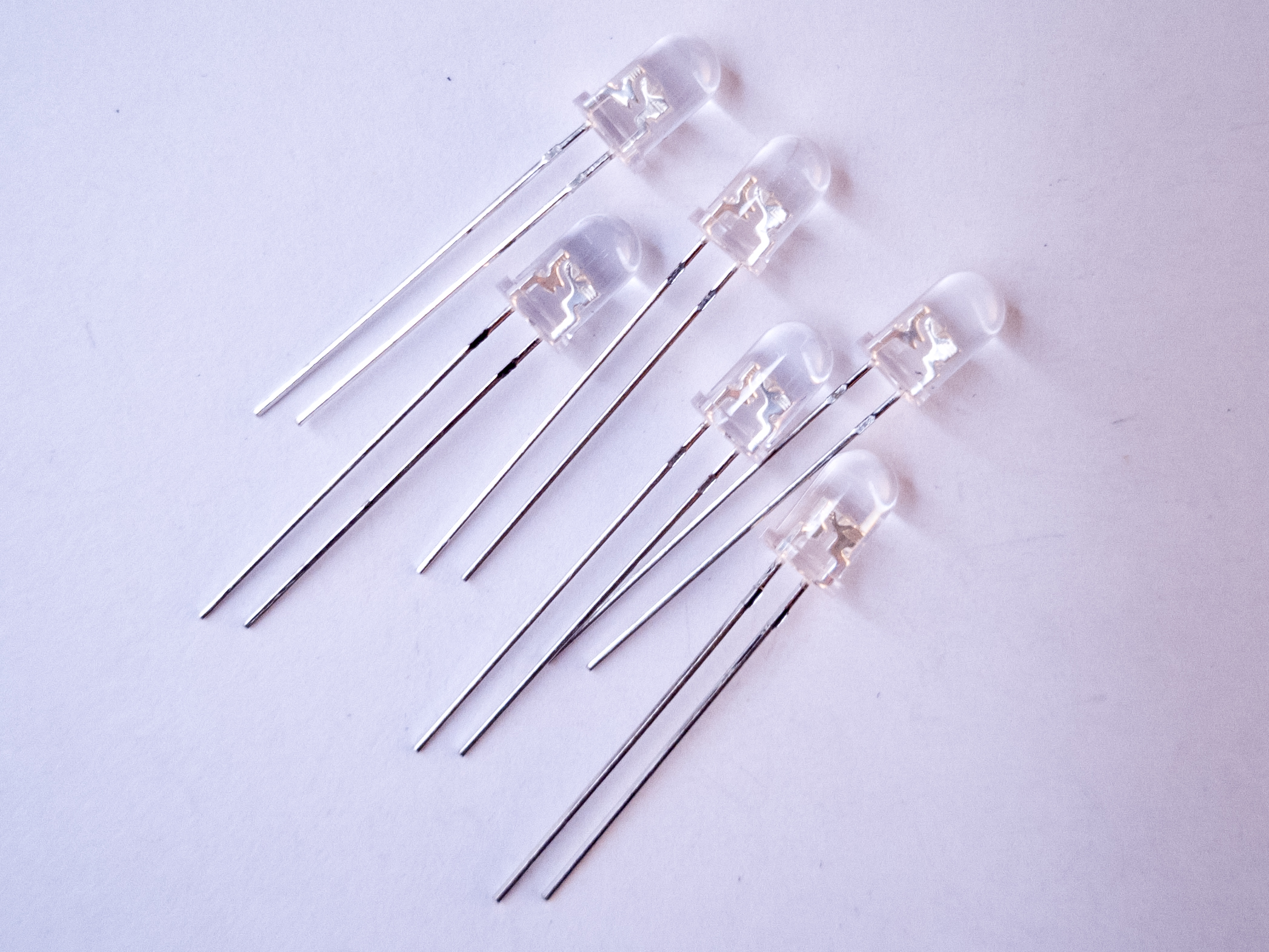
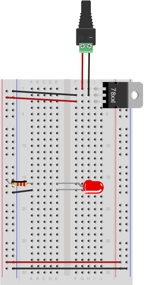
Once a circuit is complete and powered, you should learn to read voltages between different points in the circuit. Wire a 7805 5-Volt voltage regulator on a breadboard as shown above and connect it to power. If you don’t have one, you can use the 5V or 3.3V output from an Arduino instead, as explained above. Now add an LED and a 220-ohm resistor to the breadboard as shown in Figure 23.
Figure 23. Breadboard view of a 220-ohm resistor and an LED powered by a 5-volt regulator.
Note how the long leg, or anode, of the LED goes to voltage through the resistor, and the short leg, or cathode, goes to ground. Next you’re going to measure voltage in this circuit.
Voltage is a measure of the difference in electrical potential energy between two points in a circuit. It’s always measured between two points in a circuit. Measuring the voltage between the two sides of a component like an LED tells you how much voltage that component uses. When you’re measuring voltage between one side of a component and another, for example, it’s called measuring the voltage drop “across” the component.
Set your multimeter to measure DC volts (Figure 24). The voltage regulator you’re using can take an input voltage range of about 8 to 15 volts, and it outputs 5 volts, so you know that no voltage you’ll read in this circuit is over 15 volts. If your meter has a variety of ranges for DC volts, choose a range that ‘s closest to, and greater than, 15 volts. For example, many meters have a setting for 20 volts, meaning that they can read up to 20V DC at that setting.
Figure 24. Multimeter set to measure voltage. Note the horizontal and dashed lines indicating DC.
Measure for voltage between the power and ground bus rows on the breadboard. You should have 5 volts, or very close to that.
Now measure the voltage drop across the LED (Figure 25). When you’re measuring the voltage drop across a component, you put the meter probes in parallel with the component. In this case, the voltage across both the component and the meter will be the same.
Figure 25. Breadboard view of measuring voltage across an LED. The red lead is on the anode and the black lead is on the cathode of the LED.
Did you get a negative voltage? Why would that happen? That means you placed the red probe on the point of lower voltage, and the black probe on the point of higher voltage. In other words, you reversed the polarity.
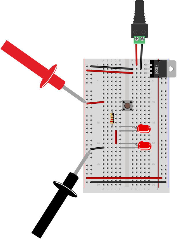
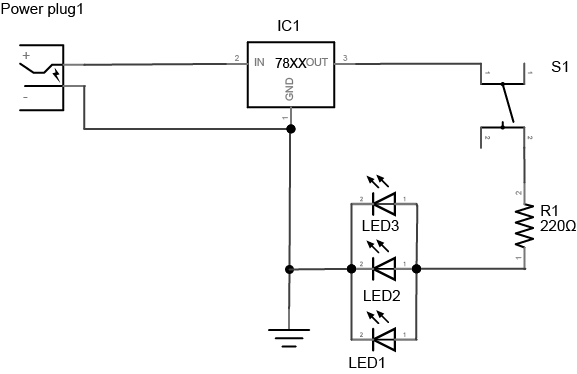
A Switched LED Circuit
Now you’re going to make a more complex circuit. Disconnect the board from power and add a switch in series with the LED and resistor as shown in Figure 26 and 27. Remember, long leg (anode) goes to voltage, short leg (cathode) goes to ground).
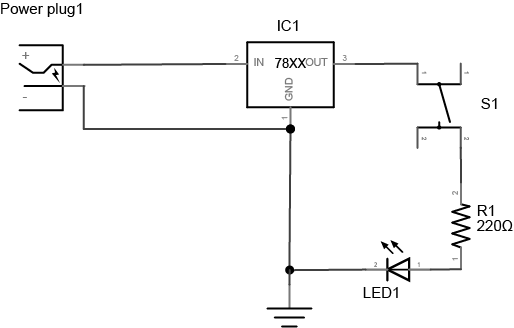
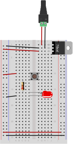
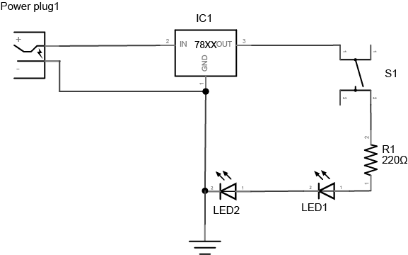
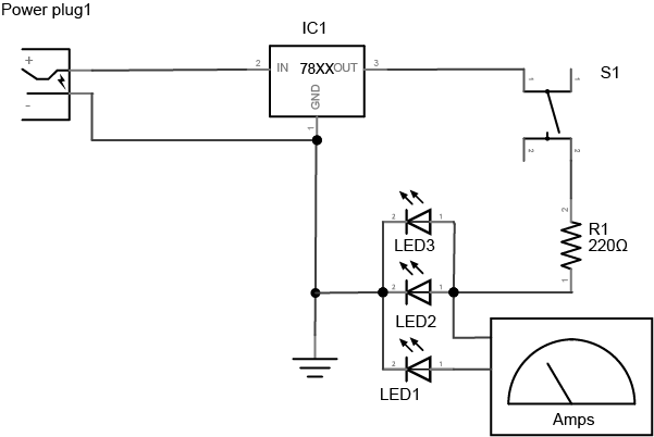
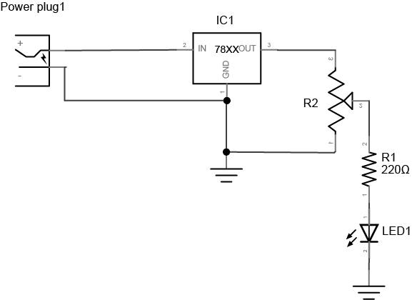
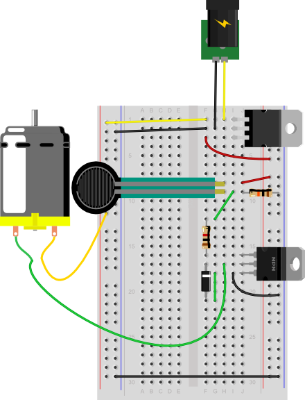
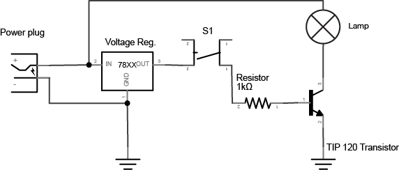
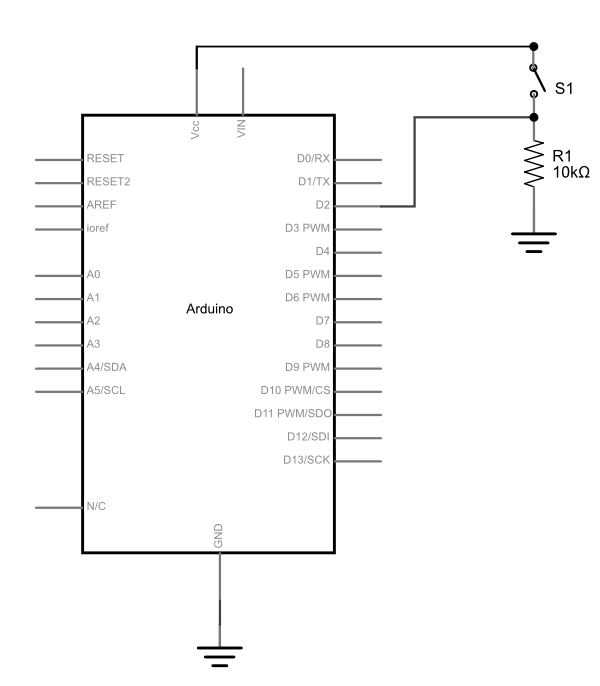
Figure 26. Schematic view of a pushbutton controlling an LED. A DC power supply of 8-12V is connected to the input and ground of a 7805 5V voltage regulator. The output of the regulator is connected to a pushbutton. The other side of the pushbutton is connected to one side of a 220 ohm resistor. The other side of the resistor is connected to the anode of an LED. The cathode of the LED is connected to the voltage regulator’s ground connection.
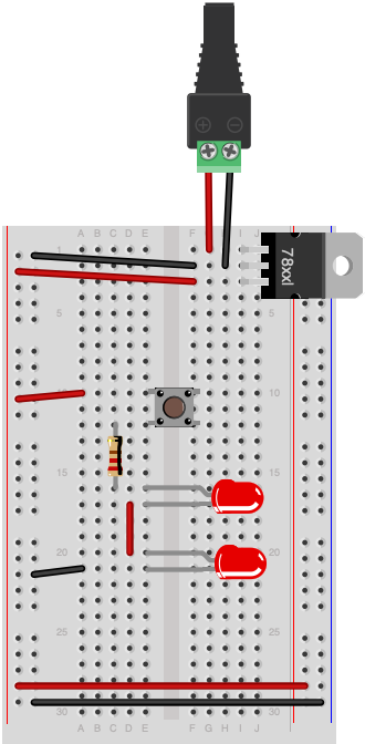
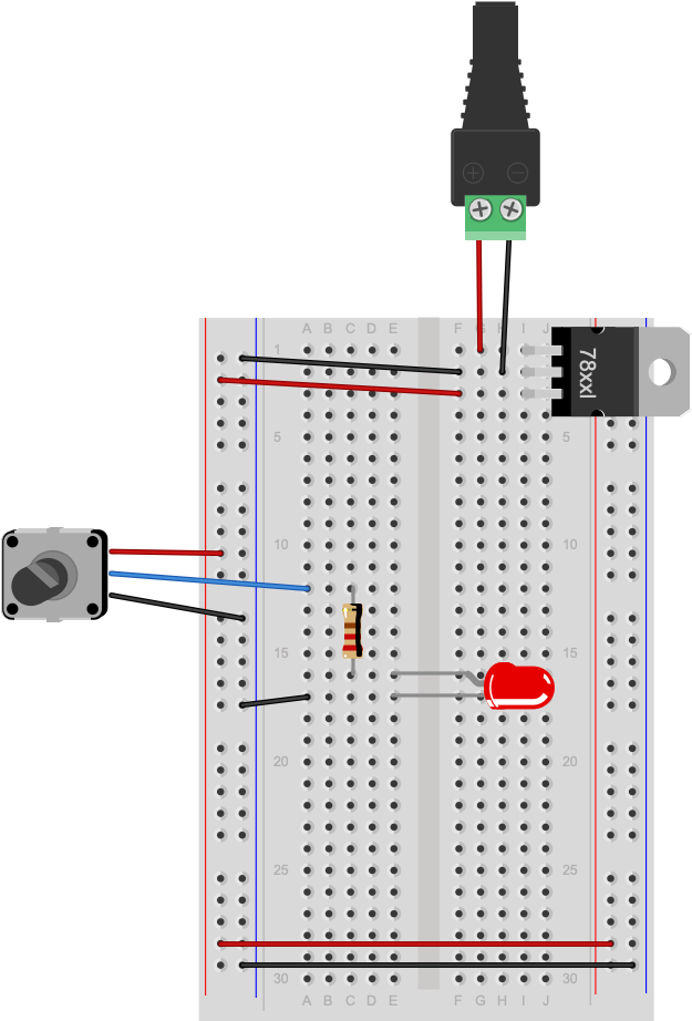
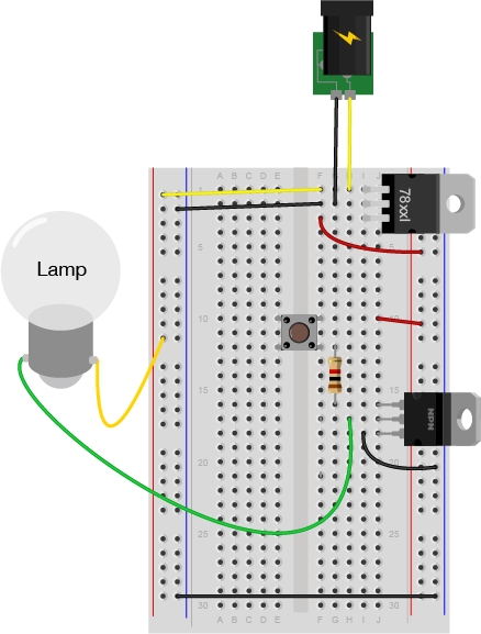
Figure 27. Breadboard view of a pushbutton controlling an LED. The components are connected as described in Figure 26.
Connect the board to your power supply and press the switch. It will illuminate the LED. Let go of the switch and it will turn the LED off again. By pressing the switch you are completing a circuit and allowing the resistor and LED to begin consuming electricity. The resistor is very important in this circuit as it protects the LED from being over-powered, which will eventually burn it out. A typical LED operates at a voltage of 2.0-2.6 volts (V) and consumes approximately 20 milliamps (mA). The resistor limits the current to a level that is safe for the LED. The higher the resistor value, the less voltage that will reach the LED. The lower the resistor value (with 0 ohms being no resistor at all), the more the voltage that will reach the LED.
Adding Up Voltage
Now, while playing with the pushbutton, measure the voltage across the pushbutton as you did in the last step, both in the on position and the off position. Is there a voltage drop across the pushbutton? What voltage do you read when the pushbutton is not pressed?
Measure the voltage across the LED and the resistor as well. Does the total voltage across all the components add up to the voltage between voltage and ground on your board? Remember, in any circuit, all of the voltage must be used up. Why? If the voltage across all the components doesn’t add up, that indicates to you that some of the electrical energy is getting converted to light, heat, and other forms of energy. No component is 100% efficient, so there’s always the possibility for some loss.
Components in Series
Change your circuit to add another LED in series with the first one, as shown in Figures 28 and 29.
Figure 28. Schematic view of a pushbutton controlling two LEDs. This circuit is similar to the one in Figure 24, but there are two LEDs in series after the resistor. The cathode of the first LED connects to the anode of the second, and the cathode of the second LED connects to the regulator’s ground.
Figure 29. Breadboard view of a pushbutton controlling two LEDs. The components are wired as described in Figure 28.
Adding Up Voltage
Measure the voltage across the resistor, as shown in Figure 30. Then measure the voltage across each LED, as shown in Figures 31 and 32. Does the total add up to the voltage from power to ground? If not, where does the missing voltage go? The remaining energy is lost as heat generated from the components.
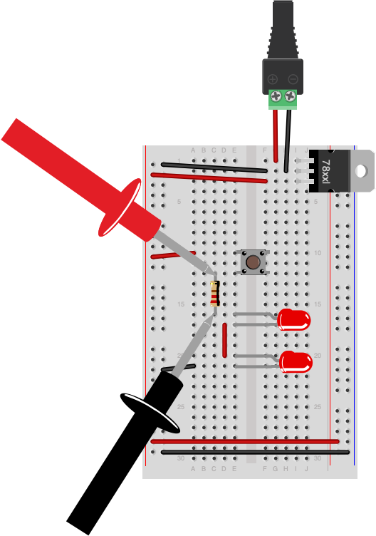
Figure 30. Measuring voltage across a resistor in a circuit. The circuit is wired as described in Figure 28. The meter’s leads are touching the two leads of the resistor.
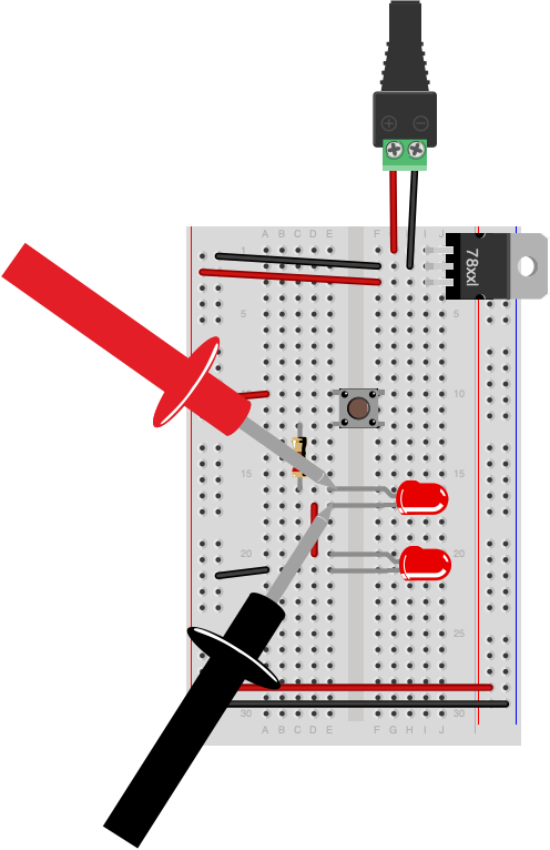
Figure 31. Measuring voltage across an LED in a circuit. The same circuit as Figure 28. The meter’s leads are touching the anode and cathode of the first LED.
Figure 32. Measuring voltage across a whole circuit. The same circuit as Figure 28. The meter’s leads are touching the power and ground buses.
Did you use two different color LEDs and get a different voltage drop across each one? That’s normal. Different color LEDs are made with different elements, and have slightly different voltage drops. Did you get no reading when you measured? Did you remember to push the button before you took your reading?
Adding a Third LED in Series
Add a third LED in series with the other two. Do the LEDs light? Why or why not? They most likely will not light up. Each LED needs about 2V to reach its forward bias and turn on. If you have three in series, and a 5-volt supply, each is getting less than the 2V it needs to turn on.
Components in Parallel/Measuring Amperage
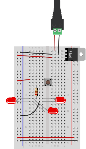
Connect three LEDs in parallel as shown in Figure 33 and 34 (remember, long leg (anode) goes to voltage, short leg (cathode) goes to ground):
Figure 33. Schematic view of a pushbutton controlling three LEDs wired in parallel. The circuit is similar to Figure 26, but the two LEDs have been replaced by three LEDs which are all in parallel. The anodes of all three LEDs are connected to the resistor, and the cathodes are all connected to the regulator’s ground connection.
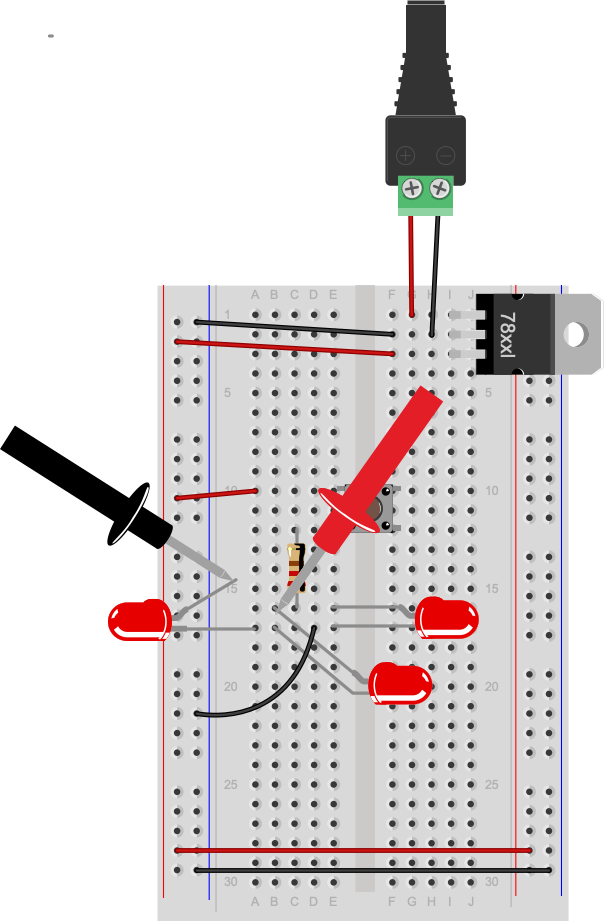
Figure 34. Breadboard view of a pushbutton controlling three LEDs wired in parallel. This circuit is wired as described in Figure 31.
Measure the voltage across each LED. It should be the same across each one.
Now you’re going to read the amperage at various points in the circuit. Move your meter’s red probe to the hole for measuring high amperage. On many meters, there are three holes, one marked “Volts/Ohms/mA”, and another marked “10A”. The right one can be used for measuring amperage when the expected amperage is less than 1A. The left is for measuring high amperage, up to 10A (Figure 35). If you’re not sure, it’s best to use the hole for 10A. Then set your meter to measure DC amperage.
Figure 35. Multimeter set to measure amperage up to 10A.
To measure the amperage through a given component, you need to place your meter in series with the component. When two components are in series, the amperage flowing through both of them is the same. For this, use the circuit with the three parallel LEDs that’s shown in Figures 36 and 37. To measure the amperage through any one of the LEDs in this circuit, you’ll need to disconnect one of the LED’s ends from the circuit (disconnect power first!) and use the meter to complete the circuit, as shown in Figures 36 and 37:
Figure 36. Schematic view of measuring amperage of one LED of three LEDs wired in parallel. This is the same circuit as shown in Figure 31, but the anode of one LED has been disconnected and then connected to one lead of a meter measuring amps. The other lead of the meter is connected to the junction between the resistor and the anodes of the other two LEDs.
Figure 37. Breadboard view measuring amperage of one LED of three LEDs wired in parallel. This circuit is wired as shown in Figure 34.
You’ll find that the amperage drawn by the LEDs is tiny, on the order of 10 or 20 milliamps at the most. That’s normal for LEDs. Make sure that you check which holes your meter probes are connected to when you’re using a meter.
Warning: Measuring amperage with the red probe in the voltage hole when you have no idea how big the current is, or measuring voltage with it in the amperage holes is a good way to damage the meter.
Generating a Variable Voltage with a Potentiometer
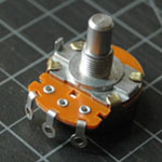
In this last step, you’ll generate a changing voltage using a potentiometer. A potentiometer is a resistor that can change its resistance. A potentiometer (or pot) has three connections. The outer connections are the ends of a fixed value resistor. The center connection connects to a wiper which slides along the fixed resistor. The resistance between the center connection and either of the outside connection changes as the pot’s knob is moved. Related video: Potentiometer schematic
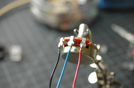
If your potentiometer does not have pins that will insert into a breadboard, then solder hook-up wires to the pot connections as shown in Figures 38 and 39.
Figure 38. A potentiometer with ring contacts, ready for soldering.
Figure 39. Potentiometer with wires successfully soldered.
Next, connect the pot to an LED and a 220-ohm resistor using the circuit shown in Figure 38:
Figure 40. Schematic view of a potentiometer controlling an LED. The two ends of a potentiometer are attached to the voltage output and ground of a 7805 voltage regulator. The middle contact of the potentiometer is connected to one end of a 220-ohm resistor. The other end of the resistor is connected to the anode of an LED. The cathode of the LED is connected to ground.
Figure 41. Breadboard view of a potentiometer controlling an LED. This circuit is wired as described in Figure 40.
As you turn the potentiometer from one end to the other, measure the voltage between the center position and ground. The pot is acting as a voltage divider, dividing the 5V into two parts. As the voltage feeding the LED goes up or down, the LED gets brighter or dimmer. The 220-ohm resistor in the circuit protects the LED from over-voltage when the resistance between the pot’s voltage lead and its center lead is 0 ohms.
Now you’ve got a basic understanding of how to use a meter to measure voltage, current, resistance, and electrical continuity. You’ll use these tests all the time.
This is an introduction to basic analog input on a microcontroller. In order to get the most out of it, you should know something about the following concepts. You can check how to do so in the links below:
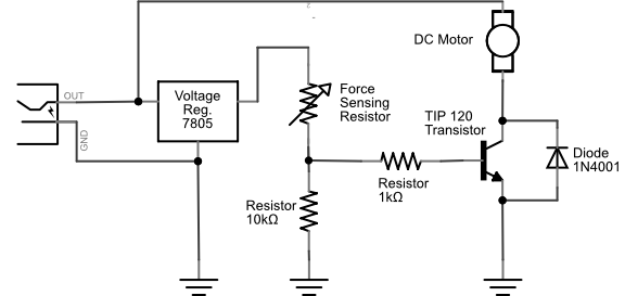
While a digital input to a microcontroller can tell you about discrete changes in the physical world, such as whether the cat is on the mat, or the cat is off the mat, there are times when this is not enough. Sometimes you want to know how fat the cat on the mat is. In order to know this, you’d need to be able to measure the force the cat exerts on the mat as a variable quantity. When you want to measure variably changing conditions like this, you need analog inputs. An analog input to a microcontroller is an input that can read a variable voltage, typically from 0 volts to the maximum voltage that powers the microcontroller itself.
Many transducers are available to convert various changing conditions to changing electrical quantities. There are photocells that convert the amount of light falling on them to a varying resistance; flex sensors that change resistance as they are bent; Force-sensitive resistors (FSRs) that change resistance based on a changing force applied to the surface of the sensor; thermistors that change resistance in response to changing heat; and many more.
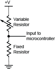
In order to read these changing resistances, you put them in a circuit and pass a current through them, so that you can see the changing voltage that results. There are a few variations on this circuit. The simplest is called a voltage divider. Because the two resistors are in series voltage at the input to the microcontroller is proportional to the ratio of the resistors. If they are equal, then the input voltage is half the total voltage. So in the circuit in Figure 1, if the variable resistor changes (for example, if it’s a flex sensor being bent), then the voltage at the input changes. The fixed resistor’s value is generally chosen to complement the variable resistor’s range. For example, if you have a variable resistor that’s 10-20 kilohms, you might choose a 10 kilohm fixed resistor.
Figure 1. voltage divider with a variable resistor and a fixed resistor
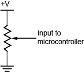
In Figure 2, you use a potentiometer, which is a variable resistor with three connections. The center of the potentiometer, called the wiper, is connected to the microcontroller. The other two sides are attached to power and ground. The wiper can move from one end of the resistor to the other. In effect, it divides the resistor into two resistors and measures the resistance at the point where they meet, just like a voltage divider.
Since a microcontroller’s inputs can read only two values (typically 0 volts or the controller’s supply voltage), an analog input pin needs an extra component to read this changing, or analog voltage, and convert it to a digital form. An analog-to-digital converter (ADC) is a device that does this. It reads a changing input voltage and converts it to a binary value, which a microcontroller can then store in memory.Many microcontrollers have ADCs built in to them. Arduino boards have an ADC attached to the analog input pins.
The ADC in the Arduino can read the input voltage at a resolution of 10 bits. That’s a range of 1024 points. If the input voltage range (for example, on the Uno) is 0 to 5 volts, that means that the smallest change it can read is 5/1024, or 0.0048 Volts. For a 3.3V board like the Nano 33 IoT, it’s 0.0029 volts. When you take a reading with the ADC using the analogRead() command, the microcontroller stores the result in memory. It takes an int type variable to store this, because a byte is not big enough to store the 10 bits of an ADC reading. A byte can hold only 8 bits, or a range from 0 to 255.
The command in Arduino is the analogRead() command, and it looks like this:
sensorReading = analogRead(pin);
Pin is the analog input pin you are using;
sensorReading is an integer variable containing the result from the ADC.
The number produced in sensorReading is will be between 0 and 1023. Its maximum may be less, depending on the circuit you use. A potentiometer will give the full range, but a voltage divider for a variable resistor like a force sensing resistor or flex sensor, where one of the resistors is fixed, will not.
The analog inputs on an Arduino (and in fact, on most microcontrollers), are all connected to the same ADC circuit, so when the microcontroller has to switch the ADC’s input from one pin to another when you try to read two pins one after another. If you read them too fast, you can get unstable readings. You can also get more reliable readings by introducing a small delay after you take an analog reading. This allows the ADC time to stabilize before you take your next reading.
Here’s an example of how to read three analog inputs with minimal delay and maximum stability:
Analog and digital inputs are the two simplest ways that a microcontroller reads changing sensor voltage inputs. Once you’ve understood these two, you’re ready to use a variety of sensors.
A schematic diagram is a representation of an electrical circuit, showing the electrical relationships using abstract graphic symbols rather than realistic pictures of components.
There are some components that schematics commonly include: voltage, ground, resistors, diodes, light emitting diodes (LED), switches, relays, capacitors.
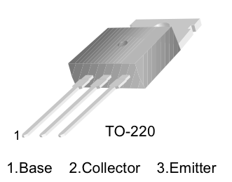
A transistor includes three connections: a base, a collector and a emitter. It can work as an amplifier and a switch.
In schematics, to show a junction point, draw a dot at crossing.
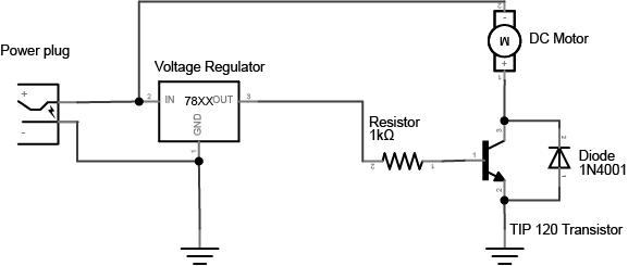
In this tutorial, you’ll learn how to control a high-current load with a transistor.
Introduction
Transistors are often used as electronic switches, to control loads which require high voltage and current from a lower voltage and current. The most common example you’ll see of this in a physical computing class is to use an output pin of a microcontroller to turn on a motor or other high current device. The output pins of a microcontroller can only produce a small amount of current and voltage. But when coupled with a transistor, they can control much more.
Microcontrollers aren’t the only integrated circuits that produce a low voltage and current on their output pins. There are many components that do this. You’ll see a whole range of so-called logic ICs that can’t produce very much current or voltage, but can produce a small change on their output pins that can be read as a data or control signal. The output voltage from devices is often referred to as a logic or a control voltage, as opposed to the supply or load voltage needed to control the high-current device. You can use transistors from circuits like these. For example, you might put a transistor on the output pin of a 555 timer IC (which produces a variable timing pulse), or a shift register IC (which allows you to produce multiple control signals in parallel) to control high current loads from those devices.
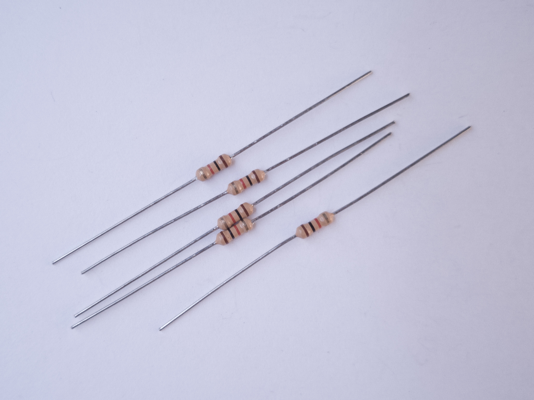
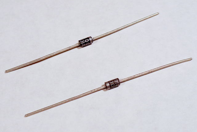
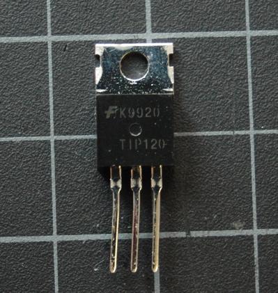
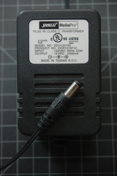
Things You’ll Need
Figures 1-12 are the parts you’ll need for this exercise.
Figure 1. A short solderless breadboard.Figure 2. 22AWG solid core hookup wires. Figure 3. 5-volt voltage regulator, model 7805 Figure 4. Resistors. You’ll need 1-kilohm and 10-kilohm for thisFigure 5. Diodes. Shown here are 1N400x power diodes.Figure 6. DC motorFigure 7. TIP120 Transistor. You can also use a MOSFET, see belowFigure 8. PushbuttonsFigure 9. PotentiometerFigure 10. Force Sensing Resistor (FSR) or other variable resistorFigure 11. DC Power SupplyFigure 12. Small Incandescent lamp bulb or LED bulb and socket
Set Up the Breadboard
Connect a 7805 5V voltage regulator to your board, and power it from a 9-12V DC power supply. Connect the ground rows on the sides together. Don’t connect the two red rows on the side of the breadboard to each other, though. Wire the breadboard so that the right side of the board receives the 5V output from the regulator, but the left side gets 9-12V directly from your DC power supply. The 5V line is the 5-volt bus or logic supply and the 9-12V line is the high-voltage bus or load supply. The two ground lines are ground. Figure 13 shows the schematic drawing and Figure 14 shows the breadboard view of the circuit explained here.
Figure 14. Schematic drawing of a DC power jack connected to a 7805 5-volt voltage regulator.
Figure 14. DC voltage jack and 7805 voltage regulator on a breadboard. The regulator is supplying 5V and ground holes are supplying voltage to the rest of breadboard.
Add a Motor and Transistor
The transistor allows you to control a circuit that’s carrying higher current and voltage from the a lower voltage and current. It acts as an electronic switch. The one you’re using for this lab is an NPN-type transistor called a TIP120. The datasheet for it can be found here. It’s designed for switching high-current loads. It has three connections, the base, the collector, and the emitter as shown in Figure 15 and Figure 16. Attach high-current load (i.e. the motor or light) to its power source, and then to the collector of the transistor. Then connect the emitter of the transistor to ground. Then to control the motor, you apply voltage to the transistor’s base. When there’s at least a 0.7V difference between the base and the emitter, the transistor will “turn on” — in other words, it’ll allow voltage and current to flow from the collector to the emitter. When there’s no voltage difference between the base and the emitter, the transistor turns off, or stops the flow of electricity from collector to emitter.
Figure 15. The schematic symbol of an NPN transistor. B is the base, C is the collector, and E is the emitter.
Figure 16. Pinout drawing of a TIP-120 transistor. From left to right the legs are labelled 1. base, 2. collector, 3. emitter.
Using a MOSFET instead of a TIP120
Figure 17. FQP30N06L MOSFET transistor pin diagram and schematic symbol
You can also use an N-channel MOSFET transistor for this. The diagram and schematic symbols are shown above in Figure 17. The IRF520 and the FQP30N06L MOSFETs are similar in function, and have the same pin configuration as the TIP120, and perform similarly. They can handle more amperage and voltage, but are more sensitive to static electricity damage.
Connect a 1-kilohm resistor from the transistor’s base to another row of the breadboard. This resistor will limit the current to the base.
You also need to add a diode in parallel with the collector and emitter of the transistor, pointing away from ground as shown in Figure 18 and Figure 19. The diode to protects the transistor from back voltage generated when the motor shuts off, or if the motor is turned in the reverse direction. This is called a snubber diode, or protection diode. Related topics: Transistors, Relays, and Controlling High-Current Loads
Figure 18. Schematic drawing of a transistor controlling a DC motor.
Figure 19. Breadboard view of a transistor controlling a DC motor.
Be sure to add the diode to your circuit correctly. The silver band on the diode denotes the cathode which is the tip of the arrow in the schematic, as shown in Figure 20:
Figure 20. Schematic representation and physical representation of a diode.
This circuit assumes you’re using a 12V motor. If your motor requires a different voltage, make sure to use a power supply that’s appropriate. The TIP120 transistor can handle up to 30V across the collector and emitter, so make sure you’re not exceeding that. Connect the ground of the motor’s supply to the ground of your microcontroller circuit, though, or the circuit won’t work properly.
Add a Switch to Control the Transistor
To turn on the transistor, you need a voltage difference between the base and the emitter of at least 0.7V. Since the emitter is attached to ground, that means any voltage over 0.7V applied to the base will turn the transistor on.
Connect a wire from the 5-volt bus of the board (also called the regulated voltage bus) to the other end of the 1 kilohm resistor as shown above and you should see the motor turn on.
Of course, it’s inconvenient to connect and disconnect a wire like this, so use a switch instead.
Remove the red wire connecting the resistor to 5 volts and connect one side of a pushbutton or switch to the 5-volt bus, and the other side to the 1K resistor. Figure 21 shows the schematic drawing and Figure 22 shows the breadboard view of the circuit.
Figure 21. Schematic drawing of a transistor controlling a DC motor, with a pushbutton to turn it on and off.
Figure 22. Breadboard drawing of a transistor controlling a DC motor with a pushbutton.
Change the Switch for a Potentiometer
The voltage on the base of the transistor doesn’t have to be controlled by a switch. You can use a potentiometer, connected as a voltage divider, to produce a changing control voltage for the transistor’s base. Figure 23 shows the schematic drawing and Figure 24 shows the breadboard view of the circuit. Related video: Connecting the potentiometer
Figure 23. Schematic drawing of a transistor controlling a DC motor, with a potentiometer to change the speed.
Figure 24. Breadboard drawing of a transistor controlling a DC motor with a potentiometer.
When you turn the potentiometer, you’re producing a varying voltage on the wiper pin. That means you’re changing the voltage on the base of the transistor. Yet the motor doesn’t change its speed. It only turns on or off. When the voltage on the potentiometer’s wiper pin reaches 0.6V, the transistor will turn on. When it’s below 0.6V, the transistor will turn off. The transistor is acting like a switch, not a variable supply. If you want to vary the motor’s speed using a transistor, you need to turn the transistor on and off very fast, and change the ratio of on time to off time. This is called pulse width modulation. You’ll learn more about it in these notes on analog output from a microcontroller and see it in action in the analog lab.
Change the Potentiometer for a Voltage Divider
If you’ve understood everything so far and managed to get it to work, here’s where it gets really fun. Imaging you have a variable resistor and you want the motor to turn on when the variable resistor passes a particular threshold. For example, maybe you want to turn on the motor when a temperature changes on a thermistor (temperature sensitive resistor), or when a weight is placed on a force-sensing resistor. To make this happen, change your control circuit to include a variable resistor as shown in Figure 25 and Figure 26.
Figure 25. Schematic drawing of a transistor controlling a DC motor, with a potentiometer to change the speed.
Figure 26. Breadboard drawing of a transistor controlling a DC motor with a voltage divider.
Using a Voltage Divider to Control a Transistor
Extra credit: See if you can work out the correct resistor value for the fixed resistor of the voltage divider that will produce just the right voltage to turn the motor on when you turn on your room’s lights, and off when you turn them off.
Whoa, that blew my mind. How do I do that?
You know you need 0.7V to turn the transistor on, and less than that to turn it off. You know how to measure the resistance of a variable resistor. So find the resistance of your variable resistor with the lights on and with the lights off, and calculate what fixed resistor will give you 0.6V. The input to your voltage divider here is 5V. That means you want 4.3 volts across the variable resistor. You know that the output voltage is proportional to the ratio of the two resistors. And you know that the current running between them is the same, because they are in series. So: Voltage = current * resistance 4.3V = current * photocell resistance therefore, current = 4.3V / variable resistor resistance Then apply this to the fixed resistor: 0.7V = current * fixed resistor resistance therefore, fixed resistor resistance = current / 0.7V or: fixed resistor resistance = (4.3V / variable resistor resistance) / 0.7V
If you’re using a force sensing resistor as your variable resistor (an Interlink model 402 is shown here), you’ll probably find that they’re very sensitive. They tend to be greater than 10 megohms resistance when no force is on them and near zero when pressed. See the graph on page 3 of the datasheet for the voltage output for various fixed resistor values.
Connect a lamp instead
You could also control a lamp using a transistor. Figure 27 shows the schematic drawing and Figure 28 shows the breadboard view of the circuit. Like the motor, the lamp circuit below assumes a 12V lamp. Change your power supply accordingly if you’re using a different lamp. In the lamp circuit, the protection diode is not needed, since there’s no way for the polarity to get reversed in this circuit:
Figure 27. Schematic drawing of a transistor controlling an incandescent lamp with a pushbutton.
Figure 28. Breadboard drawing of a transistor controlling an incandescent lamp with a pushbutton.
Conclusion
A motor controlled like this can only be turned in one direction. To be able to reverse the direction of the motor, an H-bridge circuit is required. For more on controlling DC motors with H-bridges, see the DC Motor Control lab.
In this tutorial, you’ll learn how to control a DC motor’s direction using a DC Motor Driver.
Introduction
In this tutorial, you’ll learn how to control a DC motor’s direction using a DC Motor Driver.
To reverse a DC motor, you need to be able to reverse the direction of the current in the motor. The classic way to do this is using an H-bridge circuit. Though most motor driver chips these days are not in fact H-bridge circuits, the term still persists. This tutorial uses a Toshiba motor driver, the TB6612FNG, which can actually drive two DC motors. Both Sparkfun, Adafruit, and Pololu make breakout boards for the motor driver, though the Sparkfun one is shown in the examples below.
At the end of the lab, an alternative motor driver, the L9110H, is shown. This motor driver can only drive one motor at a time, unlike the TB6612FNG, but it’s more inexpensive than the TB6612FNG.
A solderless breadboard with two rows of holes along each side.
Motor Driver (H-bridge), model TB6612FNG
DC Gearmotor
10-kilohm resistors. These ones are 5-band resistors
Pushbuttons
A DC Power Jack
DC Power Supply
Figures 1-9. The parts you’ll need for this exercise. Click on any image for a larger view.
Prepare the breadboard
Connect power and ground on the breadboard to power and ground from the microcontroller. On the Arduino module, use the 5V or 3.3V (depending on your model) and any of the ground connections, as shown in Figures 10 and 11.
Figure 10. Breadboard drawing of an Arduino Uno on the left connected to a solderless breadboard on the right
Figure 10 shows an Arduino Uno on the left connected to a solderless breadboard, right. The Uno’s 5V output hole is connected to the red column of holes on the far left side of the breadboard. The Uno’s ground hole is connected to the blue column on the left of the board. The red and blue columns on the left of the breadboard are connected to the red and blue columns on the right side of the breadboard with red and black wires, respectively. These columns on the side of a breadboard are commonly called the buses. The red line is the voltage bus, and the black or blue line is the ground bus.
Figure 11. Breadboard view of an Arduino Nano mounted on a solderless breadboard.
As shown in Figure 11, the Nano is mounted at the top of the breadboard, straddling the center divide, with its USB connector facing up. The top pins of the Nano are in row 1 of the breadboard.
The Nano, like all Dual-Inline Package (DIP) modules, has its physical pins numbered in a U shape, from top left to bottom left, to bottom right to top right. The Nano’s 3.3V pin (physical pin 2) is connected to the left side red column of the breadboard. The Nano’s GND pin (physical pin 14) is connected to the left side black column. These columns on the side of a breadboard are commonly called the buses. The red line is the voltage bus, and the black or blue line is the ground bus. The blue columns (ground buses) are connected together at the bottom of the breadboard with a black wire. The red columns (voltage buses) are connected together at the bottom of the breadboard with a red wire.
Connect a pushbutton to digital input 2 on the Arduino. Figure 12 shows the schematic, Figure 13 shows the breadboard view for the Uno, and Figure 14 the breadboard view for the Nano.
Figure 12. Schematic Diagram of a pushbutton attached to an Arduino as a digital input. A 10-kilohm resistor connects from the pushbutton to ground.
Figure 13. Breadboard view of a pushbutton attached to an Arduino Uno. The Arduino is connected to a breadboard as described in the image above. A pushbutton is mounted in across the center section of the breadboard. A red wire connects from the left side voltage bus to the lower right pin of the pushbutton. A blue wire connects the upper left pin of the pushbutton to digital pin 2 on the Arduino. A 10-kilohm resistor connects the upper right pin of the pushbutton to the ground bus on the left side of the board.
Figure 14. Breadboard view of a pushbutton attached to an Arduino Nano 33 IoT.
As shown in Figure 14, the Nano is mounted across the center divide of the breadboard with the USB connector pointing up. A pushbutton is mounted in across the center section of the breadboard. A red wire connects from the left side voltage bus to the lower right pin of the pushbutton. A blue wire connects the upper left pin of the pushbutton to digital pin 2 on the Arduino. A 10-kilohm resistor connects the upper right pin of the pushbutton to the ground bus on the left side of the board.
Find a motor
Find yourself a DC motor that runs on low DC voltage within the range of 3 – 15V. This one works well for this, or this one or this one. Discarded toys and printers can be good sources of these also. The ITP free store is almost always a goldmine for discarded motors and fans. Asking classmates and second years is another good approach.
Solder leads to the motor’s terminals. The motor’s direction depends on the polarity, so it’s helpful to use different colors so you know which way the motor will turn when you hook it up.
Optional: Consider testing your motor with a bench power supply from the equipment room. Ask a teacher or resident if you need help setting one up. Begin by adjusting the voltage on the bench power supply and observe its effects. Take note of its speed at different voltages without dipping to low or too high.
Safety Warning: Running a motor at a voltage much lower or much higher than what it’s rated for could potentially damage or permanently destroy your motor. When the motor doesn’t spin, the voltage is too low. When the motor runs hot, or sounds like it’s straining, the voltage is too high.
Powering Your Motor
If your motor can run on 5V (if you’re using an Uno) or 3.3V (if using a Nano 33 IoT ) and less than 500mA, you can use the Arduino’s USB voltage. Most motors require a higher voltage and higher current draw than this, however, so you will need an external power supply. You can use any DC power supply or battery up to 15V with this motor driver as long as your motor can run at that voltage, and as long as the supply can supply as much current as your motor needs. However you choose to power this circuit, make sure the power source is compatible with your motor. For example, don’t use a 9V battery for a 3V motor.
The diagrams below show how to power the motor from an external power supply. To power directly from the Arduino’s Vcc, connect the VMOT pin of the motor driver to the Vcc pin on the Arduino (5V on Uno, 3.3V on Nano)
The TB6612FNG can handle a motor supply voltage up to 15V, and it operates on a logic voltage of 2.7–5.5V. It can control an output current of 1.2A. It has two motor driver circuits, each with two logic inputs and two motor outputs. Each motor driver has a PWM input, because they are expected to be used for speed control for the motor by pulse width modulating this pin. There’s also a Standby pin that you have to connect to voltage through a 10-kilohm pullup resistor to activate the motor driver circuits.
The motor driver has the following pins. The pin numbers shown here are for the Sparkfun breakout board. The order of the pins will be different for the Adafruit and Pololu boards. The Pins are numbered here in a DIP fashion, in a U-shape from top left to bottom left, then bottom right to top right.
VMOT – motor voltage supply input, up to 15V.
Vcc – logic voltage supply input, 2.7-5.5V
Gnd – ground
AO1 – A channel output 1. This is the first motor terminal for the first motor driver
AO2 – A channel output 2. This is the second motor terminal for the first motor driver
BO2 – B channel output 2. This is the second motor terminal for the second motor driver
BO1 – B channel output 1. This is the first motor terminal for the second motor driver
Gnd – ground
Gnd – ground
PWMB – B Channel PWM Enable. This pin controls the speed for channel B, regardless of the channel’s direction
BI2 – B channel input 2. This controls B channel output 2. To control that pin, take this pin HIGH or LOW.
BI1 – B channel input 1. This controls B channel output 1. To control that pin, take this pin HIGH or LOW.
Stdby – enables both drivers when you take it HIGH and disables them when you take it LOW
AI1 – A channel input 1. This controls A channel output 1. To control that pin, take this pin HIGH or LOW.
AI2 – A channel input 2. This controls A channel output 2. To control that pin, take this pin HIGH or LOW.
PWMA – A Channel PWM Enable. This pin controls the speed for channel A, regardless of the channel’s direction
Figure 15 shows the Sparkfun board, and Figures 16 and 17 show the Pololu board front and back. The Pololu board is labeled on the back. You can see that both boards have the same pins, even though the layouts are different.
Figure 15. Motor Driver (H-bridge), model TB6612FNG
Figure 16. Pololu’s TB6612FNG Dual Motor Driver Carrier (front view of the board)
Figure 17. Pololu’s TB6612FNG Dual Motor Driver Carrier (back of the board)
You can change the direction and speed of the motor using the motor driver. The truth table below shows how the motor driver works.
AI1
AI2
PWMA
Effect
H
L
H
Motor turns one direction
L
H
H
Motor turns the other direction
L
L
–
Motor stop
H
H
–
Motor stop
–
–
L
Motor stop
For this lab, the PWMA pin connects to a digital pin on your Arduino so you can send it either HIGH or LOW and turn the motor ON or OFF, or pulse width modulate it to control the speed. The motor logic pins are also connected to designated digital pins on your Arduino so you can set them HIGH and LOW to turn the motor in one direction, or LOW and HIGH to turn it in the other direction. The motor supply voltage connects to the voltage source for the motor, which is usually an external power supply.
Connect the motor to the Driver
Connect the motor to the driver as shown in Figures 18 – 20. Figure 18 shows the schematic, Figure 19 shows the breadboard view for an Uno, and Figure 20 shows the breadboard view for a Nano.
Figure 18. Schematic diagram of an Arduino connected to a motor driver to control a DC motor. The Arduino and switch are connected as described in the drawing above. A motor driver has been added, and is connected as follows: PWMA is connected to the Arduino’s digital pin 5. AIN1 is connected to digital pin 4. AIN2 is connected to digital pin 3 on the Arduino. AO1 and AO2 are connected to the DC motor’s two connections. The ground pins are connected to ground. VMOT is connected to the positive terminal of a DC power source for Arduino and the motor. The power source’s negative terminal is connected to ground. The motor driver’s Vcc pin is connected to the Arduino’s voltage output (5V or 3.3V depending on your model). The Standby pin is connected to voltage through a 10-kilohm resistor. The rest of the driver pins are unconnected.
Figure 19. Breadboard drawing of an Arduino connected to a motor driver to control a DC motor. The Arduino and switch are connected as described in the breadboard drawing above. A motor driver has been added, straddling the center of the breadboard. PWMA is connected to the Arduino’s digital pin 5. AIN1 is connected to digital pin 4. AIN2 is connected to digital pin 3 on the Arduino. AO1 and AO2 are connected to the DC motor’s two connections. The ground pins are connected to ground. VMOT is connected to the VIN terminal the Arduino, and the Arduino should be powered through its DC power jack. The power source’s negative terminal is connected to ground. The motor driver’s Vcc pin is connected to the Arduino’s voltage output (5V for the Uno). The Standby pin is connected to voltage through a 10-kilohm resistor. The rest of the driver pins are unconnected. A 100-microfarad capacitor has been added connecting the voltage and ground buses close to the motor driver, to act as a decoupling capacitor.
Figure 20. Breadboard drawing of an Arduino Nano connected to a motor driver to control a DC motor. The Arduino and switch are connected as described in the breadboard drawing above. A DC power jack has been added, connected to the Nano’s ground and Vin pin (pins 14 and 15, respectively). A motor driver has been added, straddling the center of the breadboard. PWMA is connected to the Arduino’s digital pin 5. AIN1 is connected to digital pin 4. AIN2 is connected to digital pin 3 on the Arduino. AO1 and AO2 are connected to the DC motor’s two connections. The ground pins are connected to ground. VMOT is connected to the Nano’s Vin pin, which is connected to the positive terminal of the DC power source for the motor. The power source’s negative terminal is connected to ground. The motor driver’s Vcc pin is connected to the Arduino’s voltage output (3.3V). The Standby pin is connected to voltage through a 10-kilohm resistor. The rest of the driver pins are unconnected. A 100-microfarad capacitor has been added connecting the voltage and ground buses close to the motor driver, to act as a decoupling capacitor.
Note on decoupling capacitors
If you find that your microcontroller is resetting whenever the motor turns on, add a capacitor across power and ground close to the motor. The capacitor will smooth out the voltage dips that occur when the motor turns on. This use of a capacitor is called a decoupling capacitor. Usually a 10 – 100uF capacitor will work. The larger the cap, the more charge it can hold, but the longer it will take to release its charge.
Program the microcontroller
Program the microcontroller to run the motor through the driver. First set up constants for the switch pin, the two motor driver pins, and the PWM enable pin of the motor driver. Use pin 5, one of the pins that can produce a PWM signal using analogWrite(), for the PWM enable pin.
const int switchPin = 2;    // switch input
const int motor1Pin = 3;    // Motor driver leg 1 (pin 3, AIN1)
const int motor2Pin = 4;    // Motor driver leg 2 (pin 4, AIN2)
const int pwmPin = 5;       // Motor driver PWM pin
In the setup(), set all the pins for the motor driver as outputs, and the pin for the switch as an input. Then set the PWM enable pin high so the driver can turn the motor on.
void setup() {
    // set the switch as an input:
    pinMode(switchPin, INPUT);

    // set all the other pins you're using as outputs:
    pinMode(motor1Pin, OUTPUT);
    pinMode(motor2Pin, OUTPUT);
    pinMode(pwmPin, OUTPUT);

    // set PWM enable pin high so that motor can turn on:
    digitalWrite(pwmPin, HIGH);
  }
In the main loop() read the switch. If it’s high, turn the motor one way by taking one motor driver pin high and the other low. If the switch is low, reverse the direction by reversing the states of the two pins.
void loop() {
    // if the switch is high, motor will turn on one direction:
    if (digitalRead(switchPin) == HIGH) {
      digitalWrite(motor1Pin, LOW);   // set leg 1 of the motor driver low
      digitalWrite(motor2Pin, HIGH);  // set leg 2 of the motor driver high
    }
    // if the switch is low, motor will turn in the other direction:
    else {
      digitalWrite(motor1Pin, HIGH);  // set leg 1 of the motor driver high
      digitalWrite(motor2Pin, LOW);   // set leg 2 of the motor driver low
    }
  }
Once you’ve seen this code working, try modifying the speed of the motor using the analogWrite() function, as explained in the Analog Lab. Use analogWrite() on the PWM enable pin of the motor, and see what happens as you change the value of the analogWrite().
An Alternative Motor Driver
If you don’t have a TB6612FNG motor driver, or if you want something simpler and less expensive, the L9110H driver will also control a DC motor’s direction and speed. It can handle and input voltage of 2.5V-12V at 800mA of current. It can drive only one motor, unlike the TB6612FNG, and it can’t control stepper motors like that driver can. But it is inexpensive.
THe L9110H comes in an 8-pin DIP package. There are two inputs, labeled the A and B channels, and they are connected to two outputs, also labeled A and B. Your motor connects to the outputs and your control pins connect to the inputs. Vcc connects to the motor supply and GND connects to ground. Its pins, numbered from top left in a U shape as usual, are as follows:
OA – output for the A channel
Vcc – motor supply voltage
Vcc – motor supply voltage
OB output for the B channel
GND – ground
IA – input for the A channel
IB – input for the B channel
GND – ground
Figure 21 shows the schematic, and Figures 22 and 23 show it connected to an Uno and a Nano 33 IoT, respectively.
Figure 21. Schematic view of an L9110H H-bridge motor driver connected to an Arduino. A pushbutton is connected to pin 2 of the Arduino as shown in the circuits above. An external DC power supply is connected to the Arduino and the motor as shown in the circuits above as well, along with a 100-microfarad decoupling capacitor. A DC motor is connected to pins OA and OB of the H-bridge. Pins Vcc are both connected to the DC power supply and pins GND are connected to ground. Pin IA is connected to pin 5 of the Arduino, and pin IB is connected to pin 6 of the Arduino. Figure 22. Breadboard view of an L9110H H-bridge motor driver connected to an Arduino Uno. A pushbutton is connected to pin 2 of the Arduino as shown in the circuits above. The L9110H straddles the center divide of the breadboard with pins 1 and 8 facing the top of the diagram. The Arduino should be powered through its DC power jack. The Vin pin of the Arduino connects to the L9110H’s Vcc pins (physical pins 2 and 3). The motor is connected to the L9110H’s OA and OB pins (physical pins 1 and 4). A 100-microfarad decoupling capacitor is connected to the voltage and ground buses on the breadboard. Pins GND (physical pins 5 and 8) are connected to ground. Pin IA (physical pin 6) is connected to pin 5 of the Arduino, and pin IB (physical pin 6) is connected to pin 6 of the Arduino.Figure 23. Breadboard drawing of an Arduino Nano connected to a L9110H H-bridge motor driver to control a DC motor. The Arduino and switch are connected as described in the breadboard drawing above. A DC power jack has been added, connected to the Nano’s ground and Vin pin (pins 14 and 15, respectively). The L9110H straddles the center divide of the breadboard with pins 1 and 8 facing the top of the diagram. The Vin pin of the Arduino connects to the L9110H’s Vcc pins (physical pins 2 and 3). The motor is connected to the L9110H’s OA and OB pins (physical pins 1 and 4). A 100-microfarad decoupling capacitor is connected to the voltage and ground buses on the breadboard. THe L9110H’s ins GND (physical pins 5 and 8) are connected to ground. Pin IA (physical pin 6) is connected to pin 5 of the Nano, and pin IB (physical pin 6) is connected to pin 6 of the Nano.
To control the motor, you take one input high and the other low, just like with the previous motor driver. Since this driver has no PWM pin, you have to pulsewidth modulate the high input to manage speed control, though.
The program below controls the L9110H, setting the speed to about half the maximum whenever you push the button. To make a variable speed you could add a potentiometer and change the value of the speed variable using the potentiometer.
const int switchPin = 2;  // pushbutton input
const int motor1Pin = 5;  // H-bridge leg 1 (pin 6, 1A)
const int motor2Pin = 6;  // H-bridge leg 2 (pin 7, 2A)

// speed of the motor (0-255):
int speed = 127;

void setup() {
  // set the pushbutton as an input:
  pinMode(switchPin, INPUT);

  // set all the other pins you're using as outputs:
  pinMode(motor1Pin, OUTPUT);
  pinMode(motor2Pin, OUTPUT);
}

void loop() {
  // if the pushbutton is high, motor will turn on one direction:
  if (digitalRead(switchPin) == HIGH) {
    // set leg 1 of the H-bridge low:
    digitalWrite(motor1Pin, LOW);
    // set leg 2 of the H-bridge high:
    analogWrite(motor2Pin, speed);
  }
  // if the pushbutton is low, motor will turn in the other direction:
  else {
    // set leg 1 of the H-bridge high:
    digitalWrite(motor1Pin, speed);
    // set leg 2 of the H-bridge low:
    digitalWrite(motor2Pin, LOW);
  }
}
Get creative
Motors can be used to make things move, vibrate, rise, fall, roll, creep, or whatever you can think of, in response to user input from a digital input device (switch, floor sensor, tripwire, etc). Look inside moving toys, you’ll find a number of excellent motors and gears you can re-purpose. See the innards of a cymbal monkey below as an example. Perhaps you can re-design the user interface to a toy, using the microcontroller to mediate between new sensors on the toy and the motors of the toy.
If you used a motor in this lab, consider any toys you have that have a motor you could take control over. Charley Chimp™ has a motor that’s easy to control from an Arduino, for example.
Figure 21. The guts of a Charley Chimp™ cymbal-playing monkey.