Parts And Tools Guide

You’ll use various tools, electronic components, and construction materials in Intro to Physical Computing. This guide will to how to shop for them.

You will need a modern laptop (4 years old or younger is a good rule of thumb).  Limited numbers are available for checkout from the department.  The primary software needed for class, namely the Arduino IDE, is freely downloadable. You are encouraged to download NYU’s free Adobe license as well: https://www.nyu.edu/life/information-technology/computing-support/software/software/adobe.html

Parts Available At ITP

Students in Intro to Physical Computing and IMA Creative Computing will receive a kit of parts the following parts in class from their instructors:

  • Arduino Nano 33 IoT
  • 830-point solderless breadboard
  • Jumper wire kit
  • USB micro cable
  • Force sensing resistors (FSRs), Qty. 3
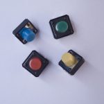
  • 4-paks of multicolor buttons (tactile switches), Qty. 2
  • 10 -kilohm potentiometers, Qty. 3
  • Rotary encoders, Qty. 2
  • phototransistors, Qty. 6
  • RC servo motor and mounting components
  • right angle gear motor
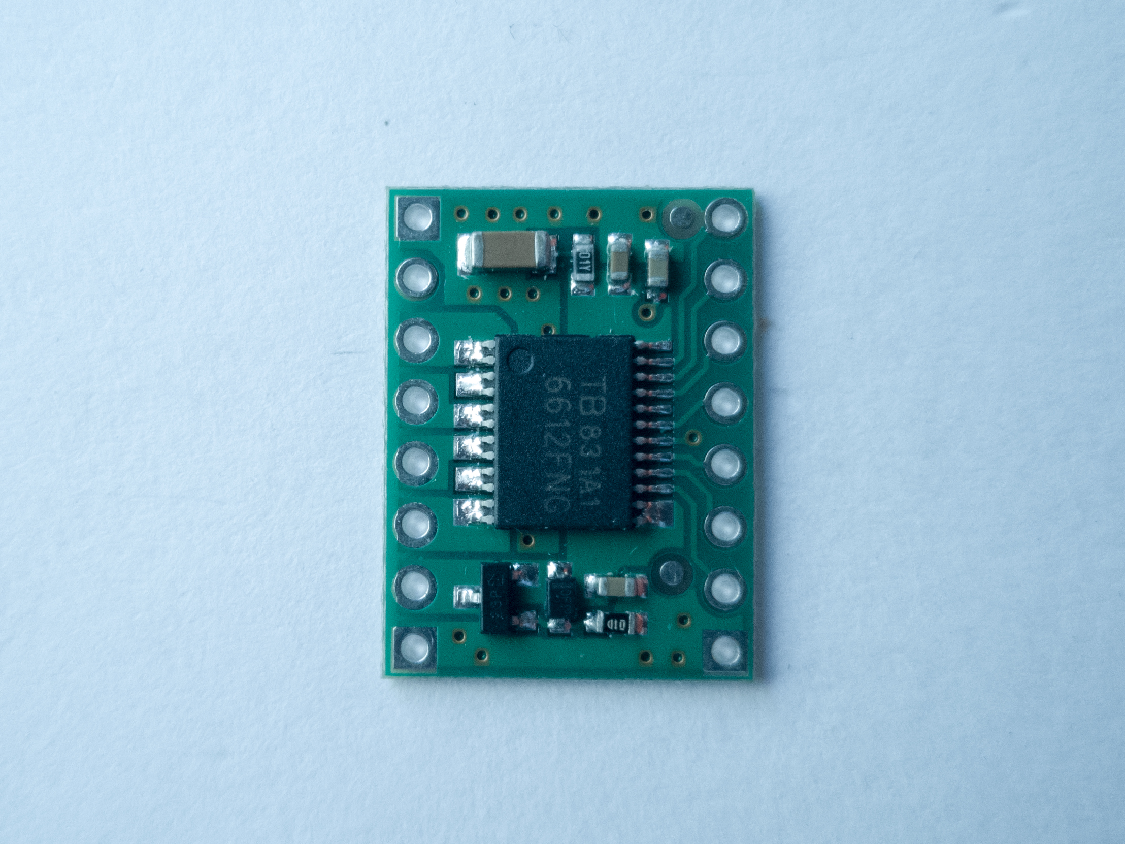
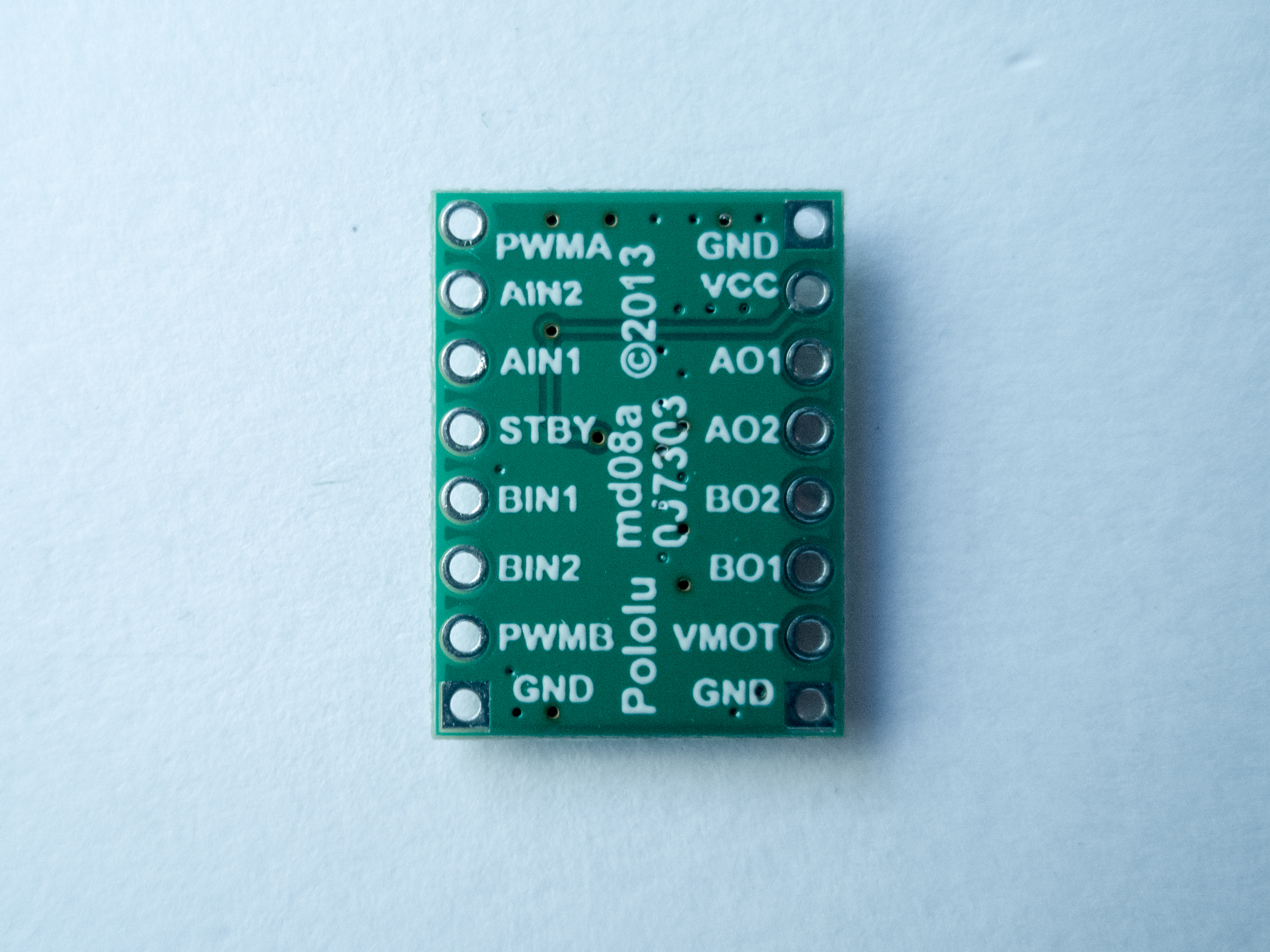
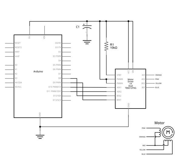
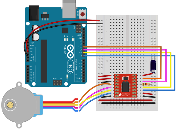
  • TB6612FNG motor driver board
  • 3″ diameter speaker, 4 ohm, 3W
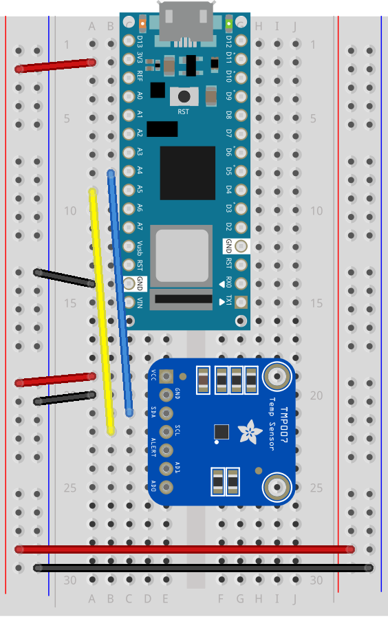
  • VL53L0X time of flight distance sensor

The parts in the kit are your major components for the lab exercises in class. You will also need some components which you can find in the shop’s component stock, including resistors, LEDs, transistors, voltage regulators, capacitors, wire, and more. You can also find tools in the shop which you can use on the floor.

When you begin to work on your larger projects, such as the midterm and final, you will likely need to buy parts for yourself, depending on what you decide to build.

Shop Component Stock

The ITP/IMA shop stocks a number of consumable electronics components. This includes potentiometers, pushbuttons, phototransistors, resistors, capacitors, voltage regulators. These are kept in the bin racks in the shop, and are available for students to take as needed. Please take only what you need for a given class exercise, as stock re-supply is not fast, and we want to make sure everyone has the parts they need. Please inform shop staff if a given part is out of stock. It is possible to do all of the lab exercises in the intro classes with parts we have in in your kit, in shop stock, or in checkout.

Beyond this, students are expected to supply electronics parts for their projects. It’s not possible to anticipate every possible component that every project might need. However, we try to stock items to help you try things before you buy. Always consult with your instructors, shop staff, and research residents on how to choose the most appropriate and economical parts for your projects.

Check-out Components

The shop also has parts available for check-out with an NYU ID, just like the equipment room. These include microcontrollers, advanced sensors, and items which may be specific to various advanced classes. These must be returned after use, just like equipment room stock. You can check out components for up to two weeks at a time.

For other parts, talk to your instructors and the resident researchers. If you’re considering a part for your project, they can advise whether it’s the right part for the job, and if there’s one available for loan on the floor, they can procure it.

When You’re Done with Components

Many students at ITP/IMA don’t continue with electronics beyond the intro classes. If you have components in good condition that you’re no longer going to use, feel free to give them to shop staff or your instructors. We’ll do our best to keep components in use and out of landfills.

Shopping for Electronic Components

The intro kits and shop component stock can supply what you will need to complete the assigned lab exercises. For your project assignments, however, you may need a wider range of sensors and/or actuators.

Learning to shop for parts is a useful electronics skill, so we’ve assembled a number of Bills of Materials on Octopart to get you started. Octopart is a site that collects part data from multiple distributors around the world. They list several vendors from our suppliers list for each part. You may find this video about online electronics vendors and this video on how to use Octopart helpful as well.

We realize students will be shopping in many different regions of the world, and Octopart lists alternative vendors that supply as many regions as possible. Mouser, Digikey, and Arrow, all on Octopart, all have outlets in China, for example; Newark, Farnell all cover Europe and the Americas well; RS Components covers the Americas, Europe, and multiple countries in Africa. We have also put together a list of similar parts on Taobao as well. With these lists, you should be able to assemble the parts you need for the labs at the best price possible. Check each vendor to see what they charge to ship to where they are. If you know of a local vendor, feel free to use them instead.

There are a few lists on Octopart that you should pay attention to. The basic parts list and the tool list will get you through most of the labs in the class. For the last two labs in the semester, and probably for your last two project assignments, you’ll need to pick from the Sensor list and the Motor or Lighting lists.

  • ITP Pcomp Basic Parts – includes the parts you’ll need for the labs in most of the semester, including the breadboard and processor and components available in the shop component stock. This list is generally 100% in stock on Digikey, one of our most used vendors, as well.
  • ITP Tool List 2020 – The shop has hand tools available for students’ use, but if you want your own tools, this list includes basic hand tools you’ll need if you don’t already have them. Lists several options for each.

Advanced lists for later in the semester:

  • ITP Pcomp Sensor List – includes more advanced sensors. These are the kinds of sensors covered in the synchronous serial labs. This list will also be handy in later project assignments, when you’re looking for sensors specific to your project’s needs.
  • ITP Pcomp Motor List – includes parts for motor and mechanical projects, used in the motors and high current lab later in the semester. May be useful in some of your project assignments as well.
  • ITP Pcomp Lighting List – includes parts for LED lighting control, used in the motors and high current lab later in the semester. May be useful in some of your project assignments as well.

Can I Get a Starter Kit?

There are many Arduino starter kits on the market, but at the moment, none of them contain all the parts we recommend for this class. In particular, there is no kit for the Nano 33 IoT microcontroller yet. You can get a kit if you prefer, but you will likely have to shop for additional parts as well.

Components in Detail

The various types of parts you’ll find in the lists, and that you’ll need for the class, are detailed below.

Microcontroller

Used in most every week’s lab.

Photo of an Arduino Nano 33 IoT module. The USB connector is at the top of the image, and the physical pins are numbered in a U-shape from top left to bottom left, then from bottom right to top right.
Figure 1. Arduino Nano 33 IoT

We’ll be working with the Arduino microcontroller platform. Recently we have switched to the Nano 33 IoT as our standard model. Most of the lab exercises are also compatible with the Arduino Uno, but the Nano 33 IoT offers some useful features that the Uno lacks, such as:

We have a guide to picking a microcontroller that may be helpful for more information. You can use any Arduino-compatible variant that you choose, and we’ll do our best to support you, but we can’t promise to know every variant on the market, there are several of dubious quality.

USB Cable

Used in most every week’s lab.

You’ll need a USB cable to connect your computer to your microcontroller as well. You can probably use one that you already have. The Nano 33 IoT has a USB Micro-B connector.

Resistors

Used in most every week’s lab.

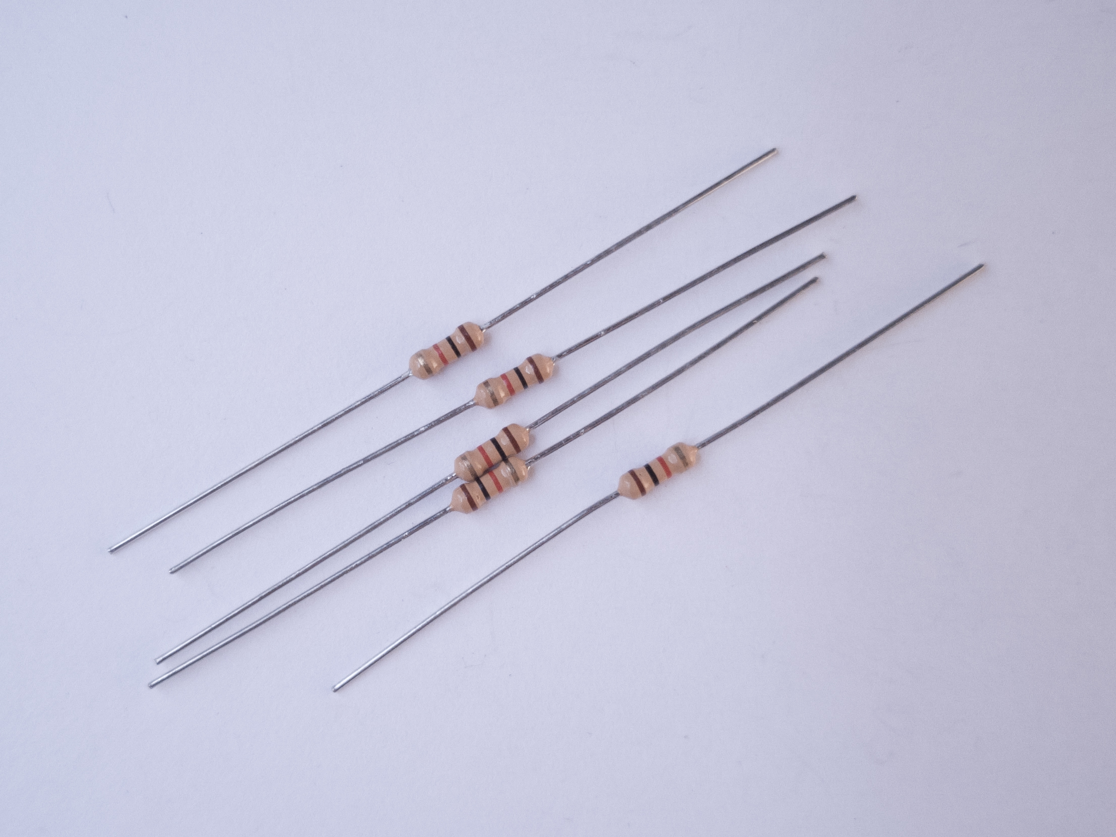
You’ll use resistors for many projects. The most common type you’ll need are 1/4 watt through-hole resistors in the values 220 ohm, 1 kilohm, and 10 kilohm. Occasionally, you might need other values as well, but most projects in this class can be done with combinations of those values. Resistors are usually bought in bulk, but there are also some handy resistor kits that contain samples of many different resistance values. A kit like this one from Sparkfun can last for a couple years of projects for the average electronics hobbyist
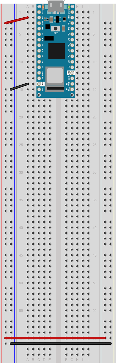
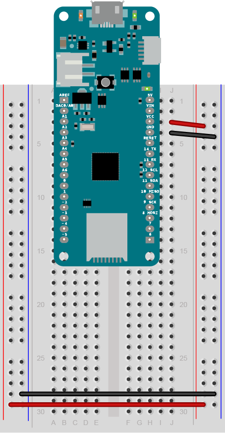
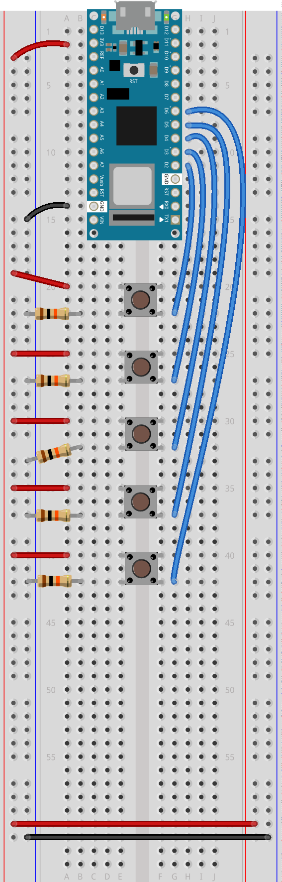
Breadboards

Used in most every week’s lab.

Photo of a solderless breadboard
Figure 5. a solderless breadboard.

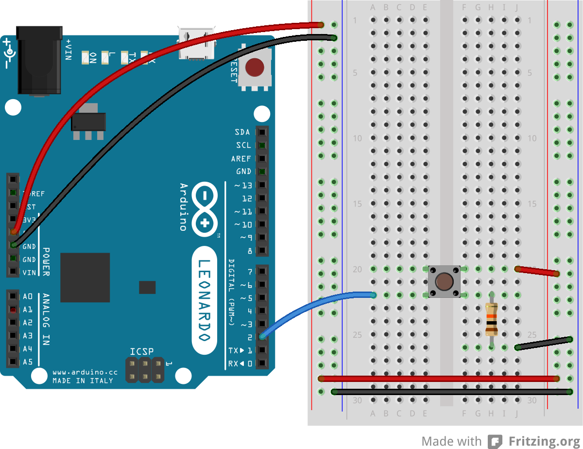
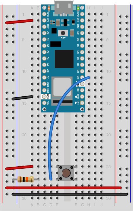
Most of your projects will be built on a solderless breadboard. There’s a lab to get you familiar with how they work. There are a few different models of these. The most common for this class are 16 x 54mm with 830 tie points and two vertical bus rows on either side. The smaller 84 x 54mm version with 400 tie points is also popular.

There are well-made breadboards, and there are cheap ones. Cheap ones seem like a good deal, but they can be difficult to use and easy to break components on. This chart compares different models of breadboards. Our favorites are from Jameco ValuePro, Twin Industries, and Bud Industries.

Breadboards can be reused for each lab, but sometimes it’s handy to have a spare.

For more permanent projects, you can use a printed circuit board to hold your components together. This requires you to solder each wire and component to the board, and cannot be disassembled, so it’s really only used for finished devices. There are some perma-proto boards with the same layout as a standard solderless breadboard that make transferring your circuit easy.

Wires

Used in most every week’s lab.

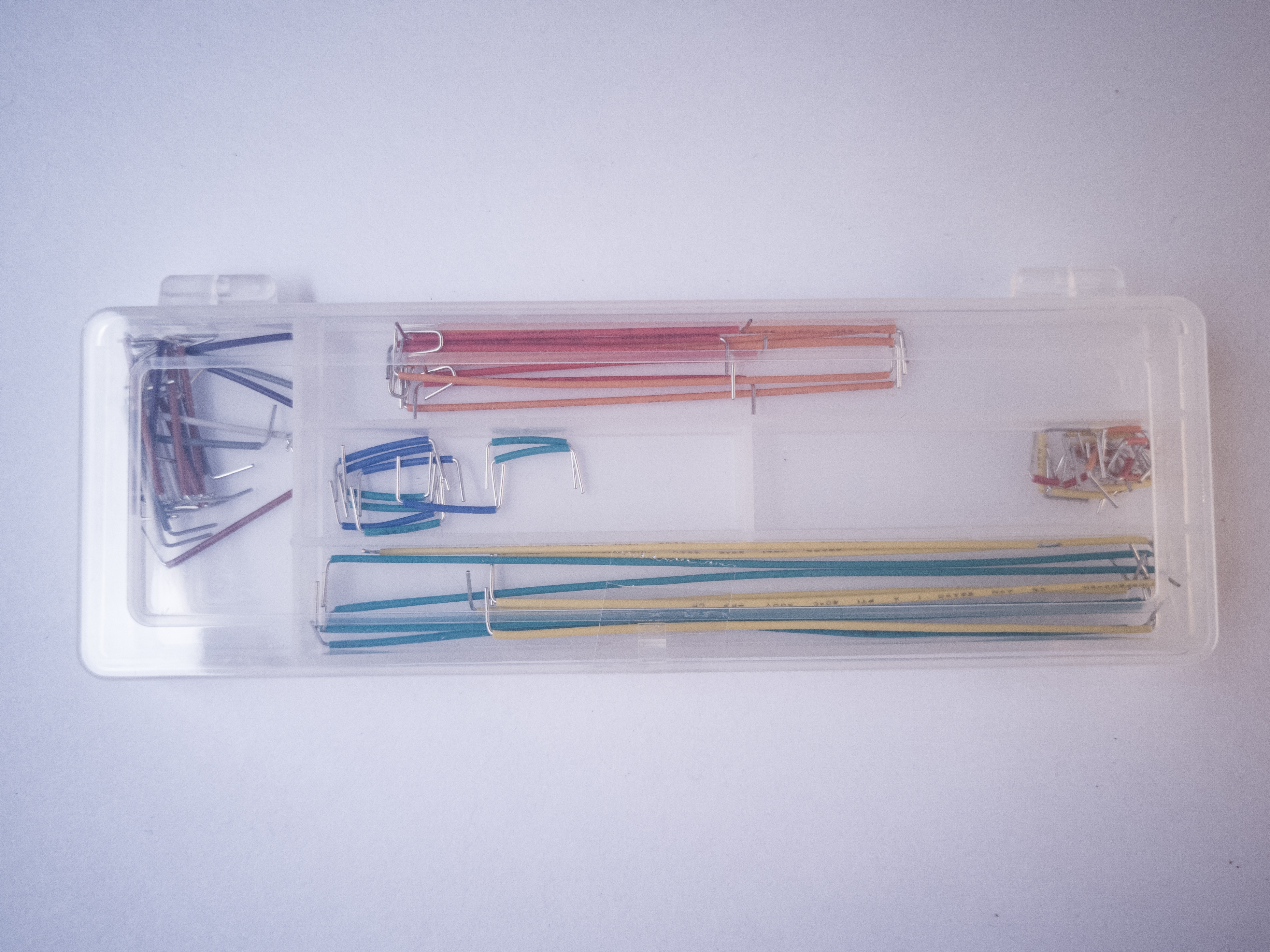
You’ll use a lot of wires to connect components on your breadboards. The breadboards support 22 AWG thickness wires. Some people prefer pre-cut solid core jumper wires, because they can lay flat on the breadboard and they insert into the board firmly. Others prefer flexible jumper wires because they’re easier to add and remove, so you can be spontaneous, but they make for a messier project, and are easy to accidentally pull out.

Another option is to order rolls of 22AWG solid core wire and custom cut your own jumper wires for each project. This is more time-consuming, but makes for a tidy and manageable board. Sometimes you can find multi-pack rolls of this wire in different colors like this one or this one. Here’s a wire options comparison list.

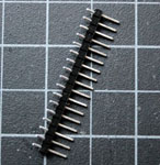
You might need some header pins as well, to solder on to wires and components. These are metal pins, spaced 0.1″ (2.54mm) apart, held together with plastic spacers.

Basic Input And Output Components

Used in most every week’s lab.

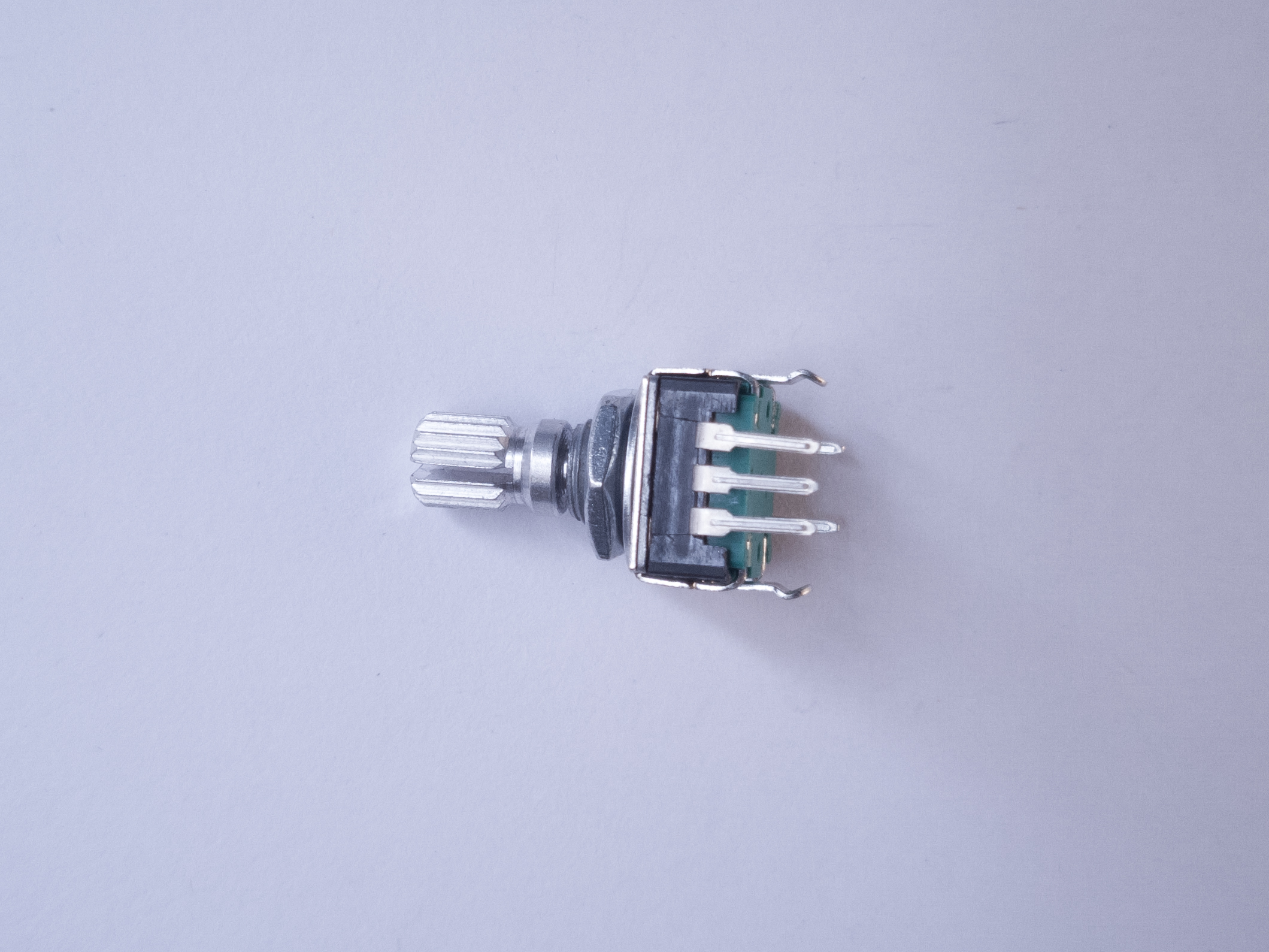
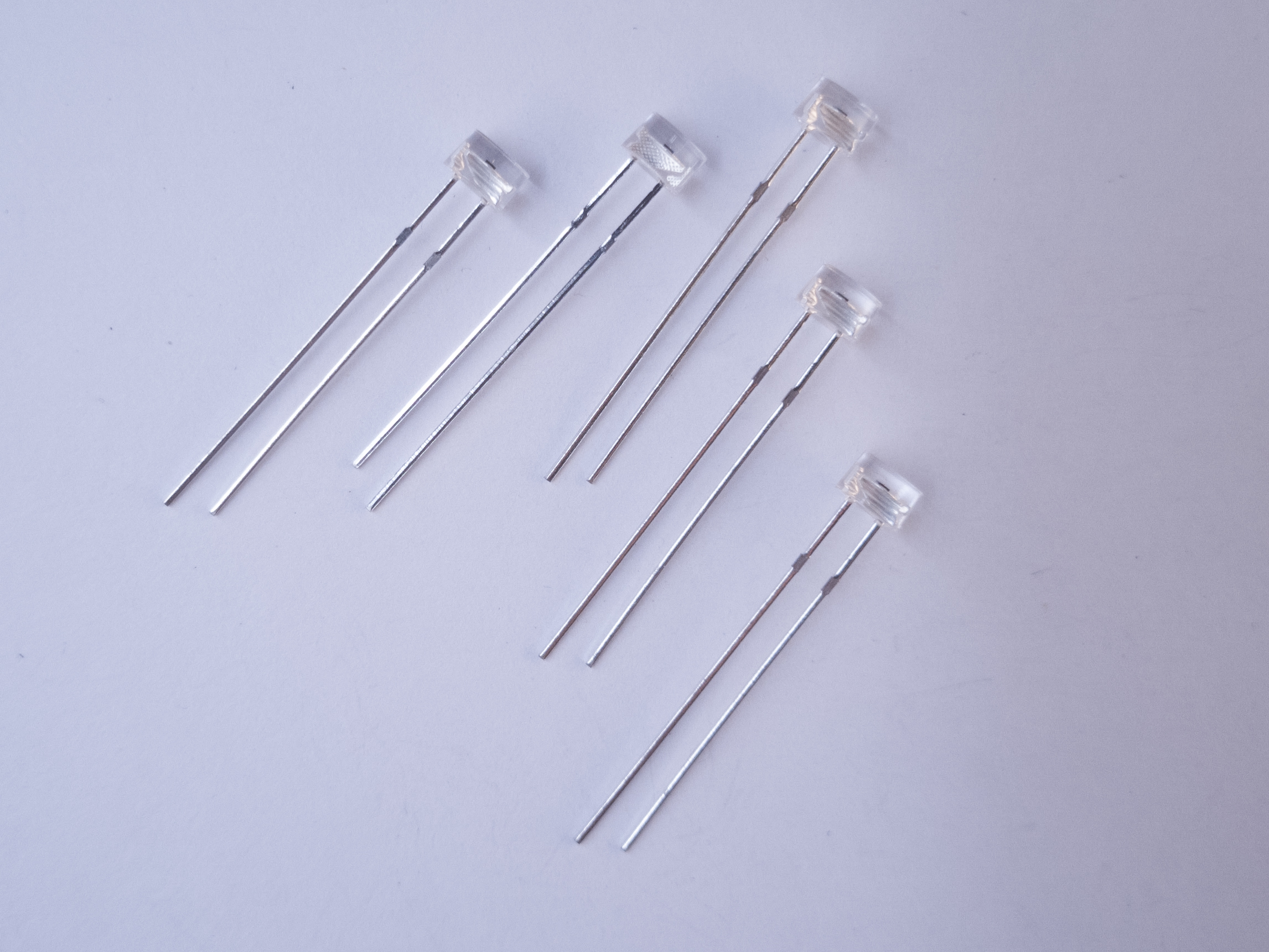
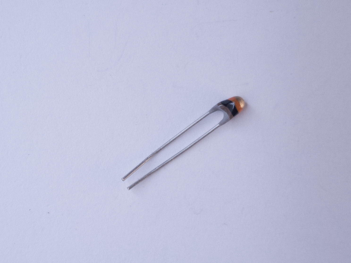
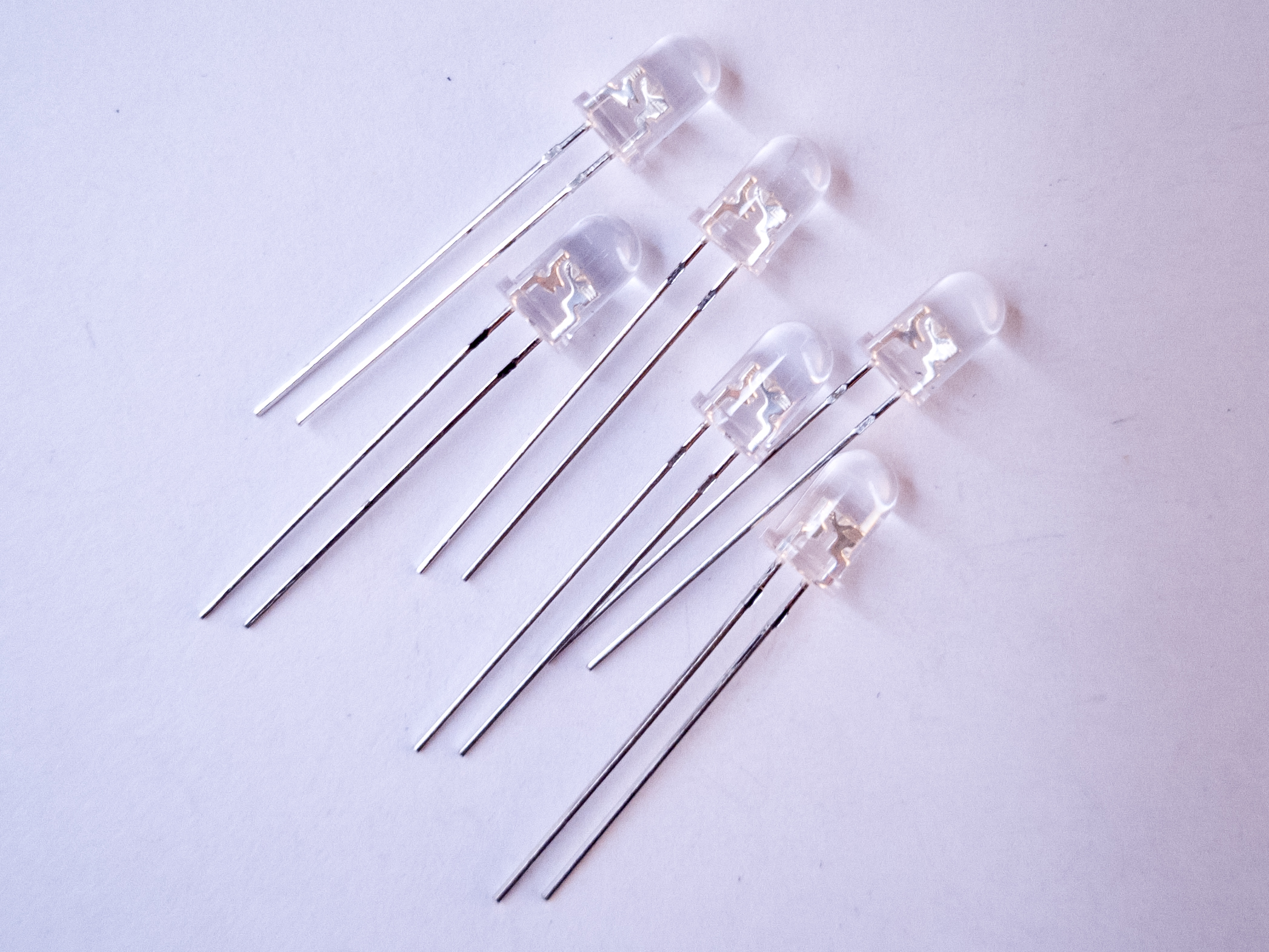
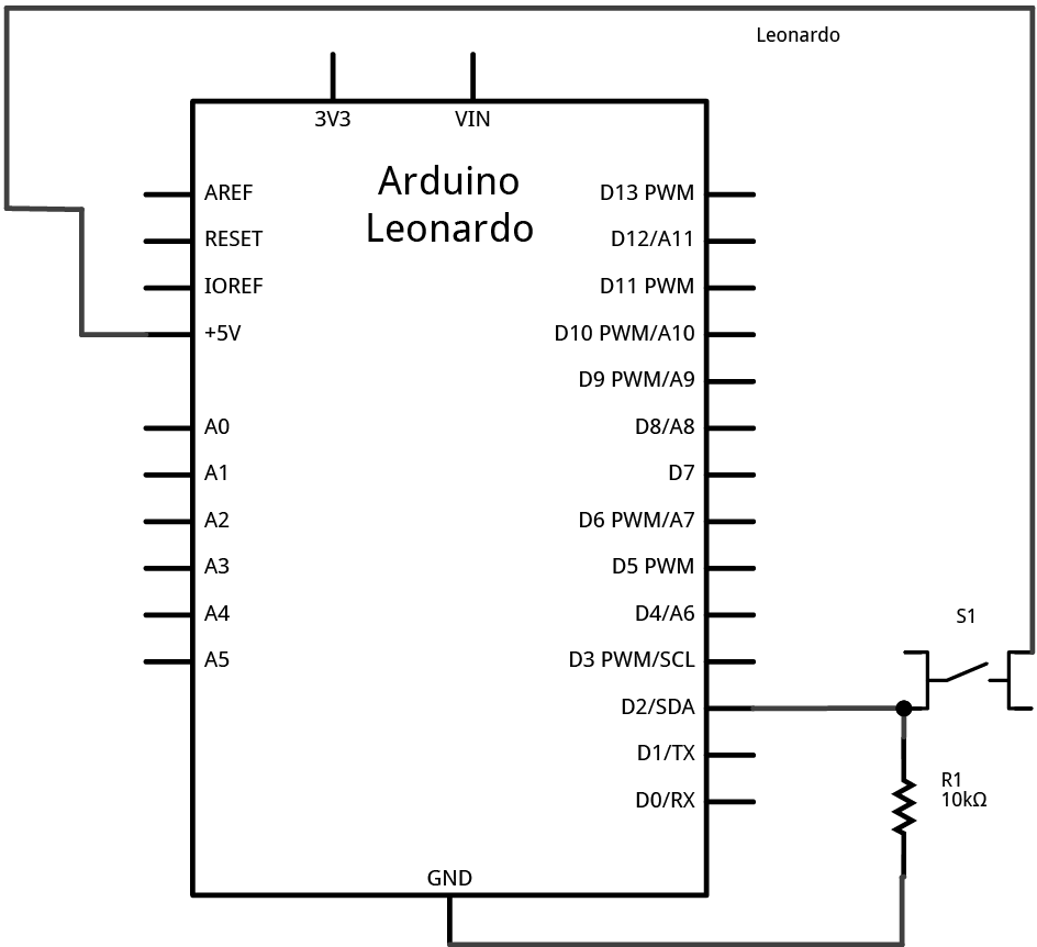
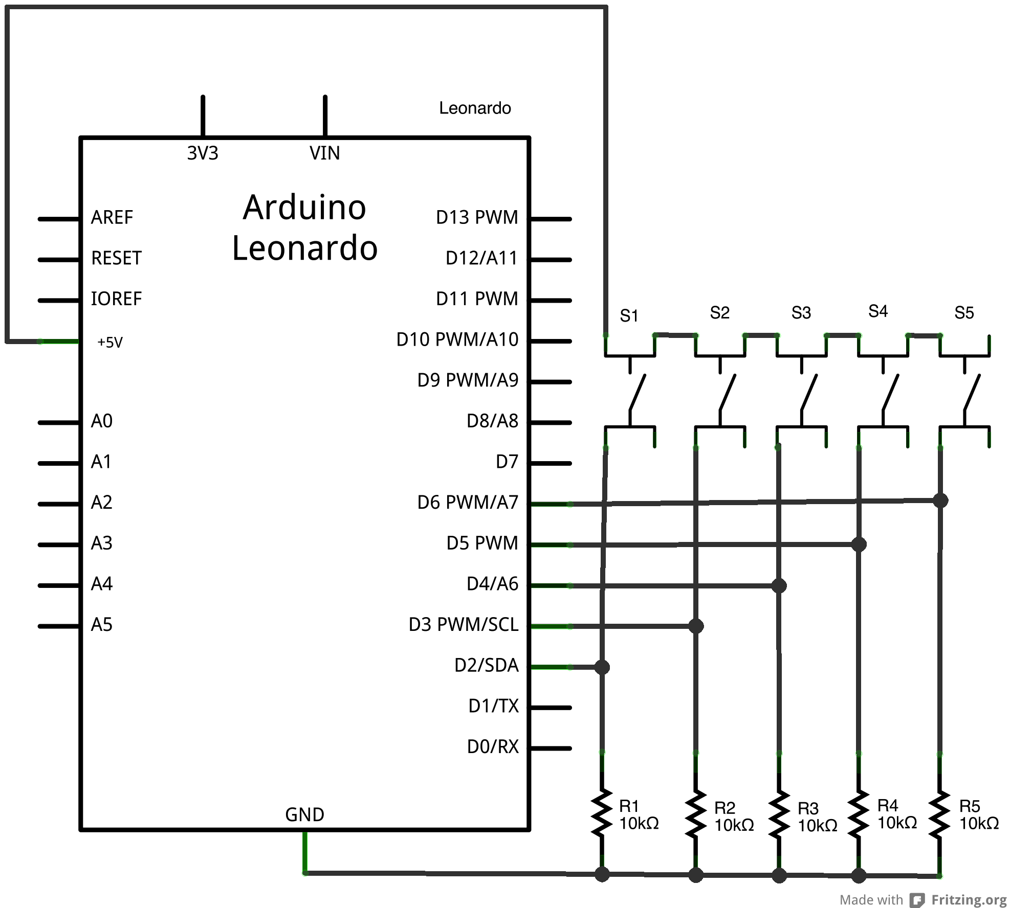
For most of the labs and many projects, you’ll use pushbuttons, switches, variable resistors called potentiometers, light emitting diodes (LEDs), speakers and/or piezo buzzers, and perhaps some variable resistors like force-sensing resistors (FSRs) or force-sensing potentiometers (FSPs). These are common and inexpensive components available from most electronic vendors. Make sure that the parts you get can be inserted into a solderless breadboard, or you will have to solder wires onto them.
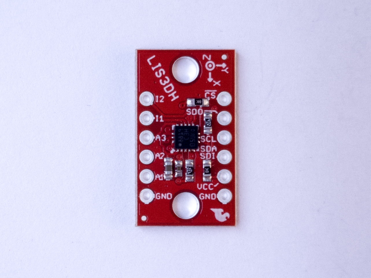
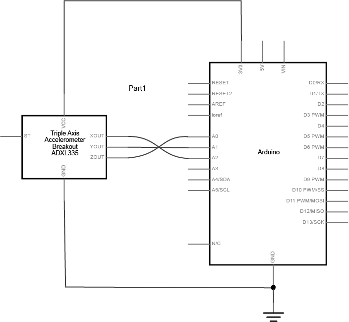
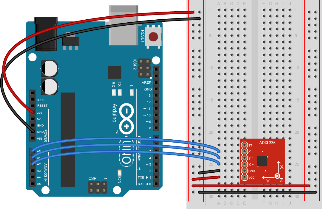
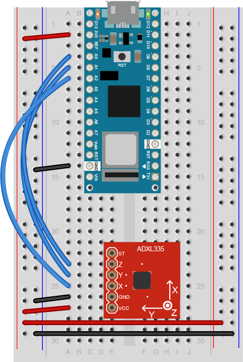
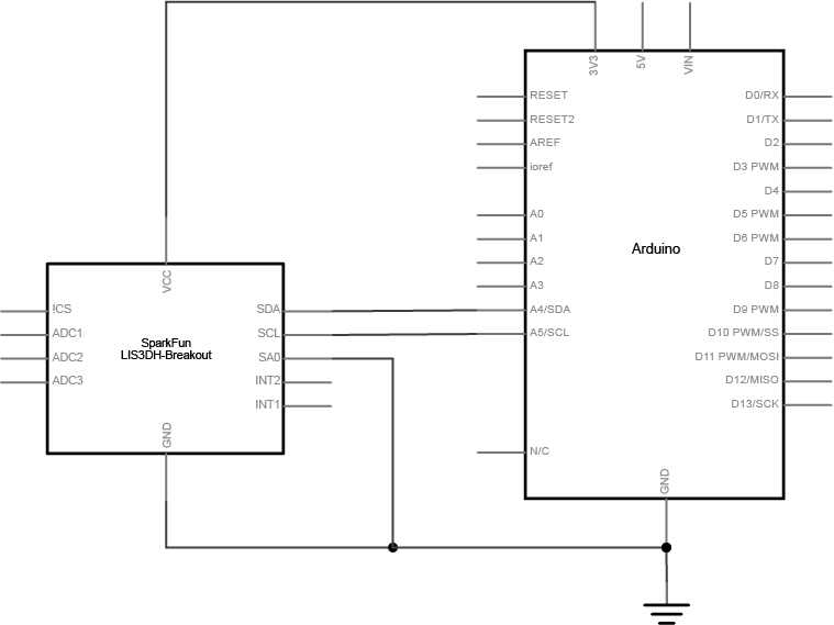
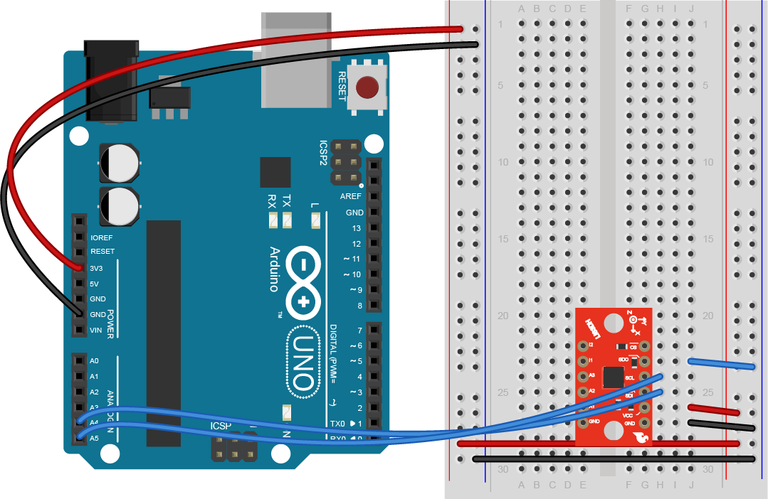
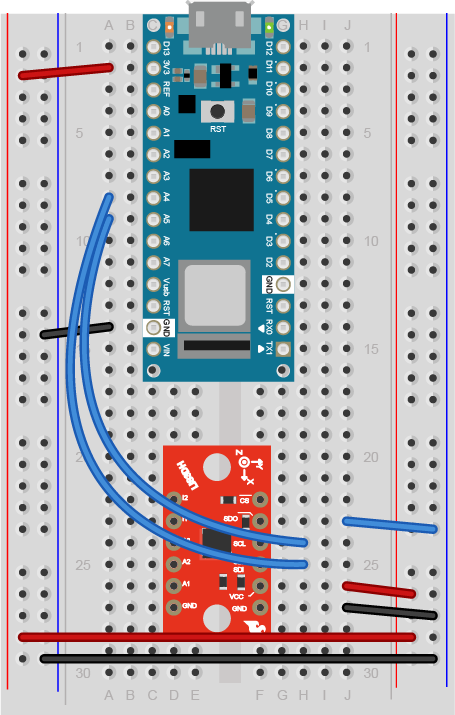
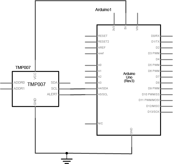
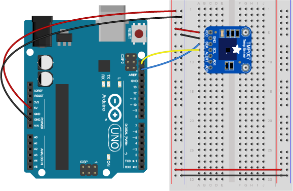
Advanced Sensors

Used in labs around mid-semester; probably in later projects as well. Check shop check-out components for a variety of sensors.

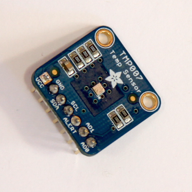
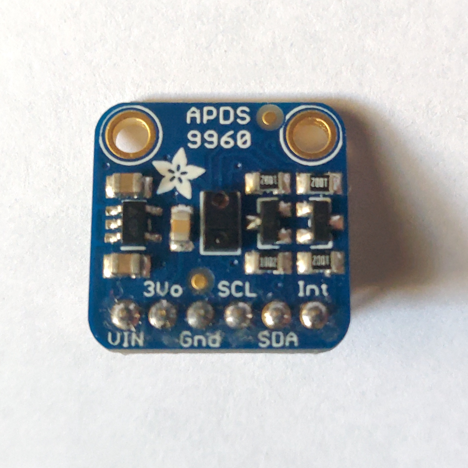
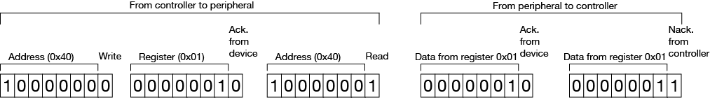
There are many advanced sensors that are very useful in this class. The Nano 33 IoT has one built-in, an inertial measurement unit (IMU) that can measure tilt and rotation. There are light sensors, distance sensors, rotation sensors, environmental sensors, air pressure sensors, and many more. Most of these are sold on breakout boards that have holes for pins that can be fitted to a solderless breadboard. You’ll need to solder on header pins for most of them, and you’ll need to learn their communications protocols. You’ll learn about these in labs in the middle of the semester. There’s an Octopart Bill of Materials that lists several of these. You’ll need to pick one for the synchronous serial lab and by then you’ll have an idea which one might also work well for you in a project. Hold off on getting these until mid-semester.

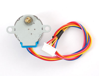
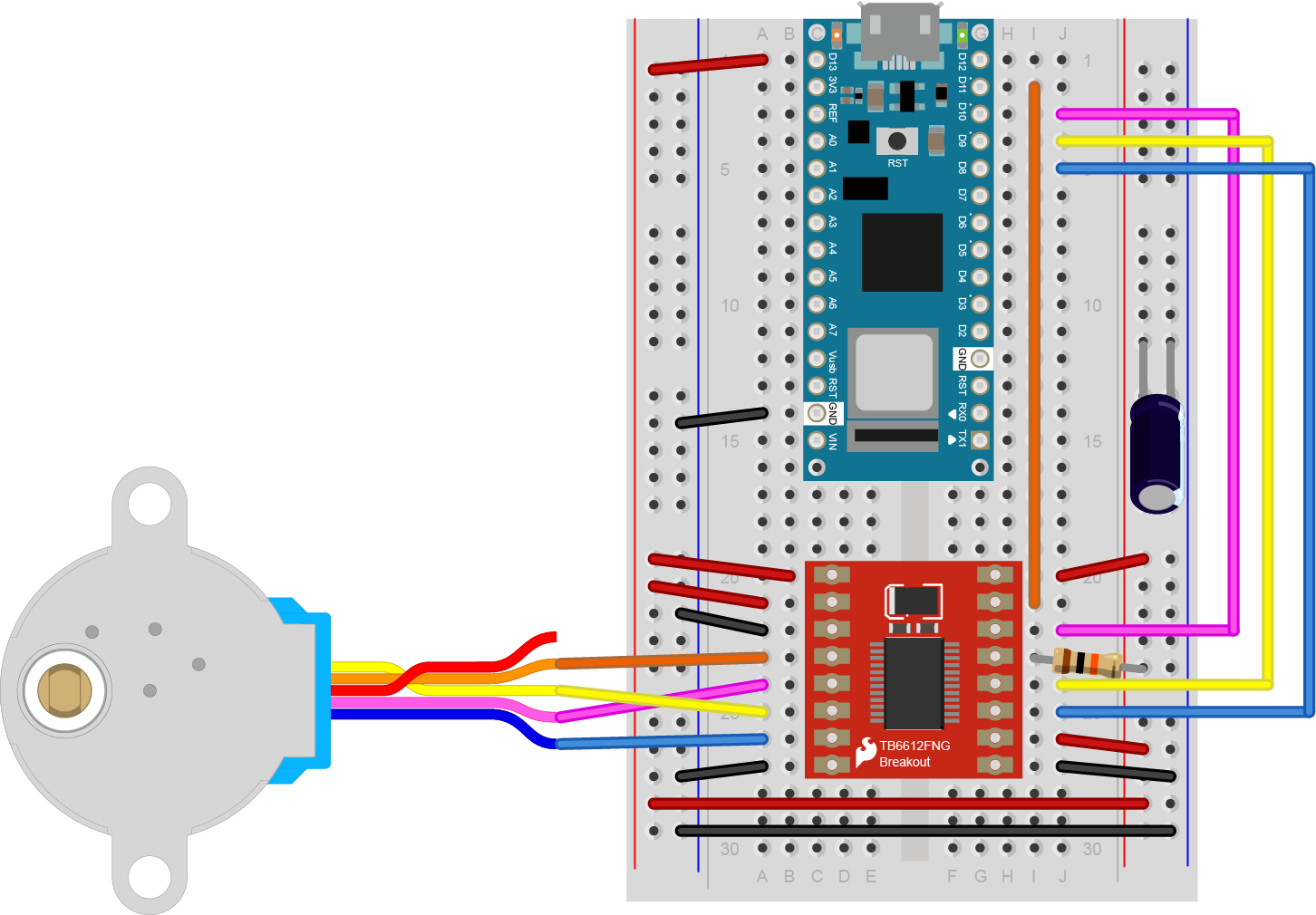
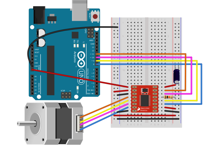
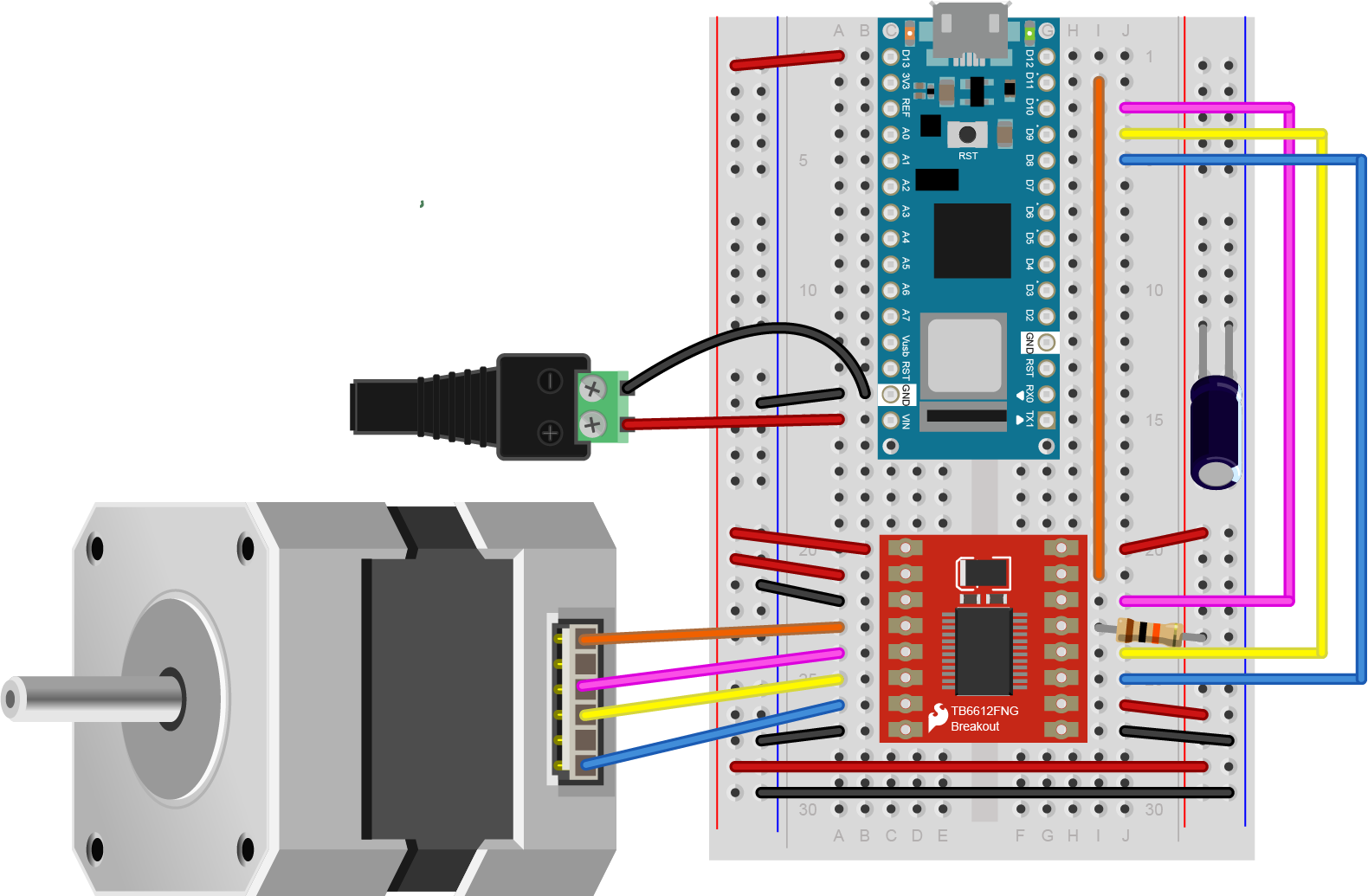
Motors and Motor Accessories

Used in labs later in semester; possibly in later projects as well.

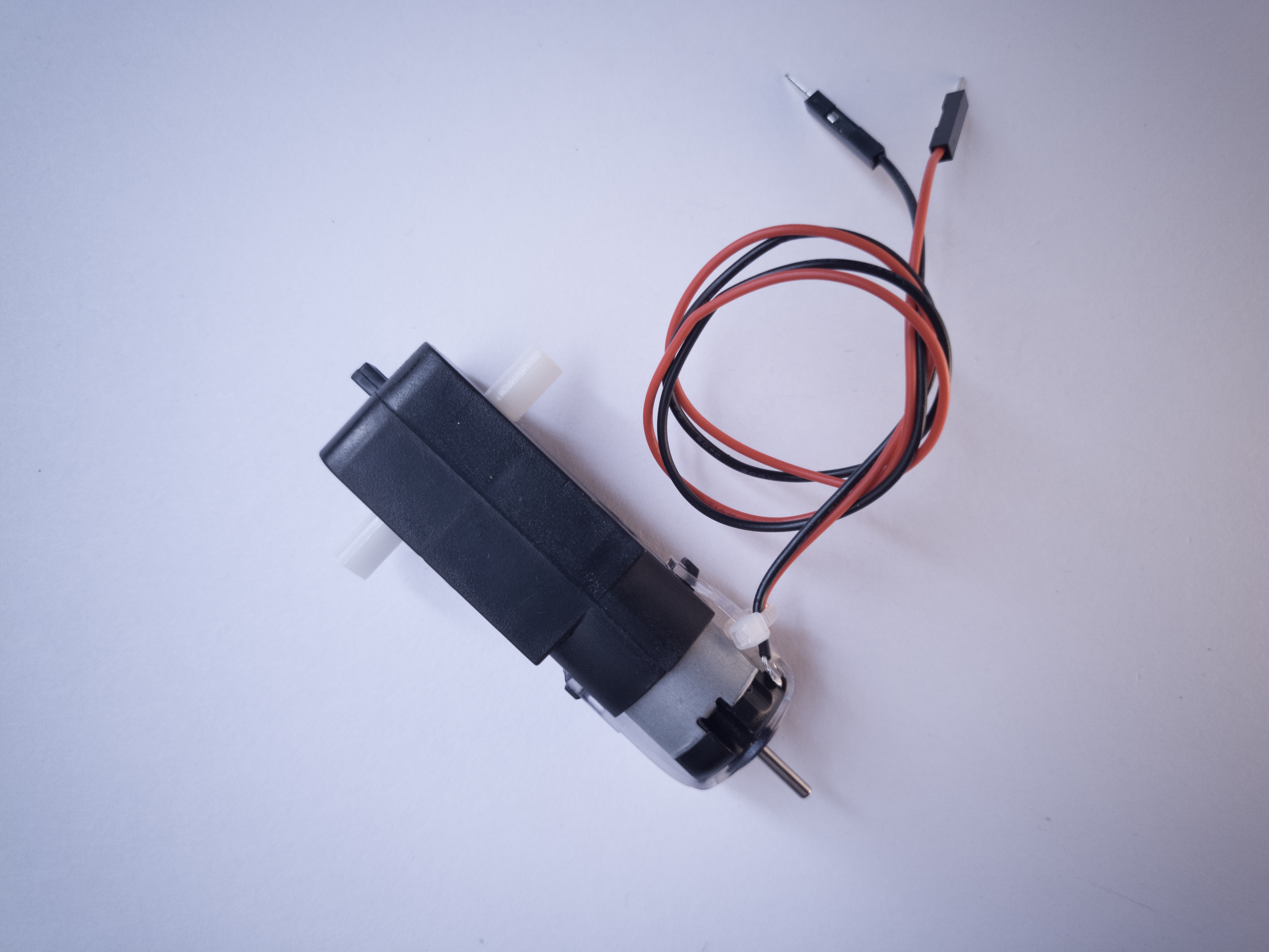
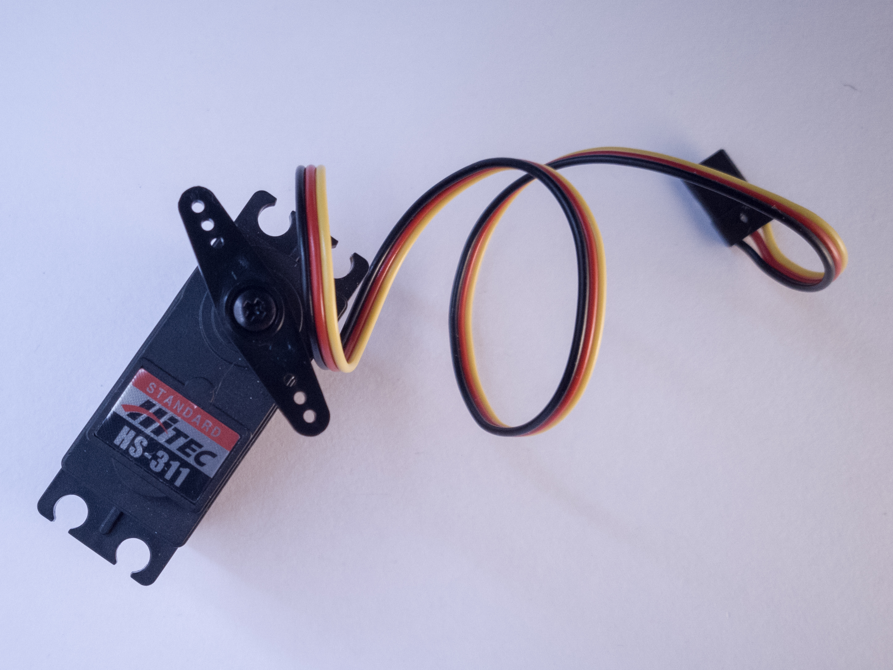
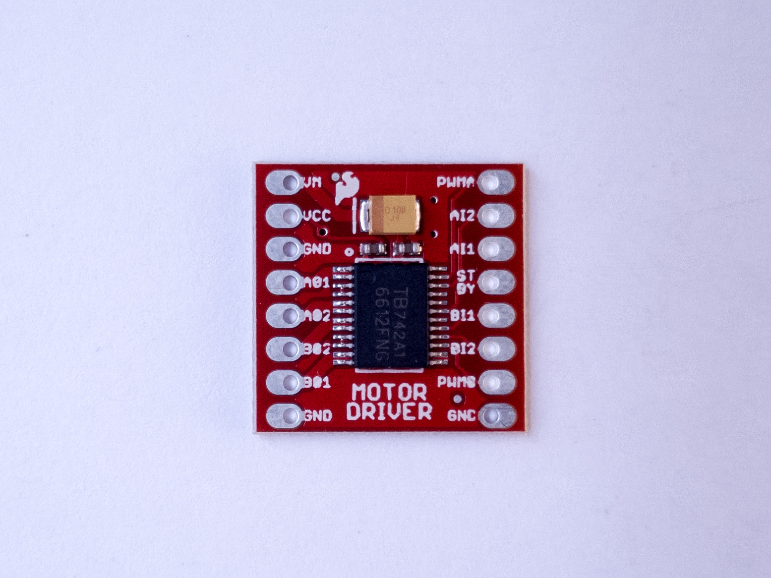
There are labs on controlling servomotors, DC motors, and stepper motors in this class, and the parts BOM lists a few we recommend. However, there is not a mechanics module to this class and the motor lab is later in the semester, so if you’re not interested in mechanical motion, you may not need motor parts. Hold off on getting these until mid-semester.

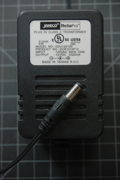
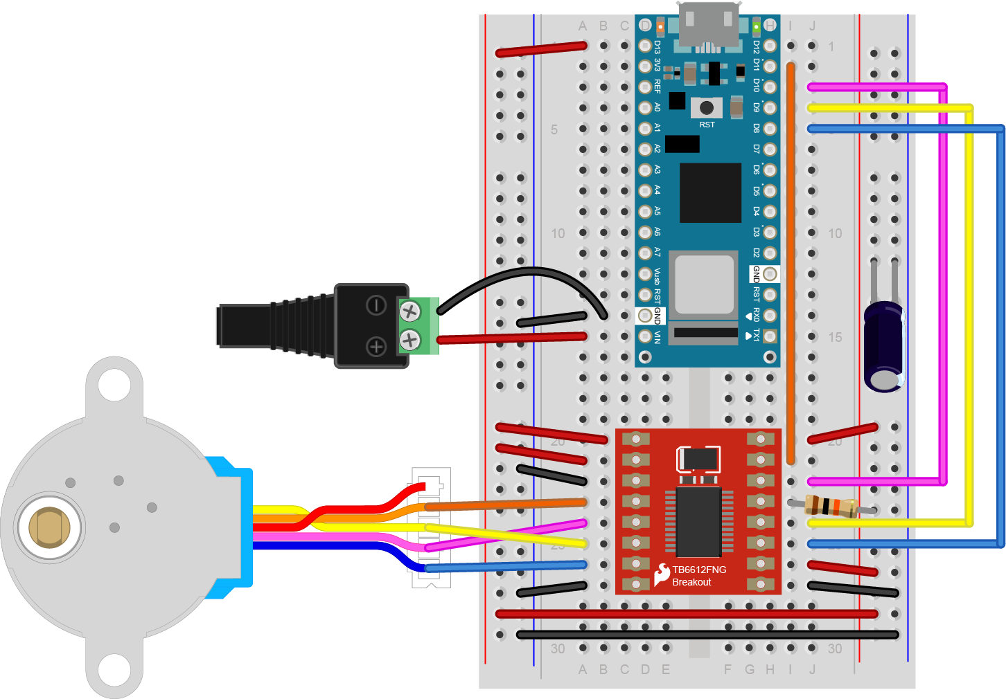
Power Supply and Regulation

Used in many projects. Regulators and jacks available in the shop component stock.
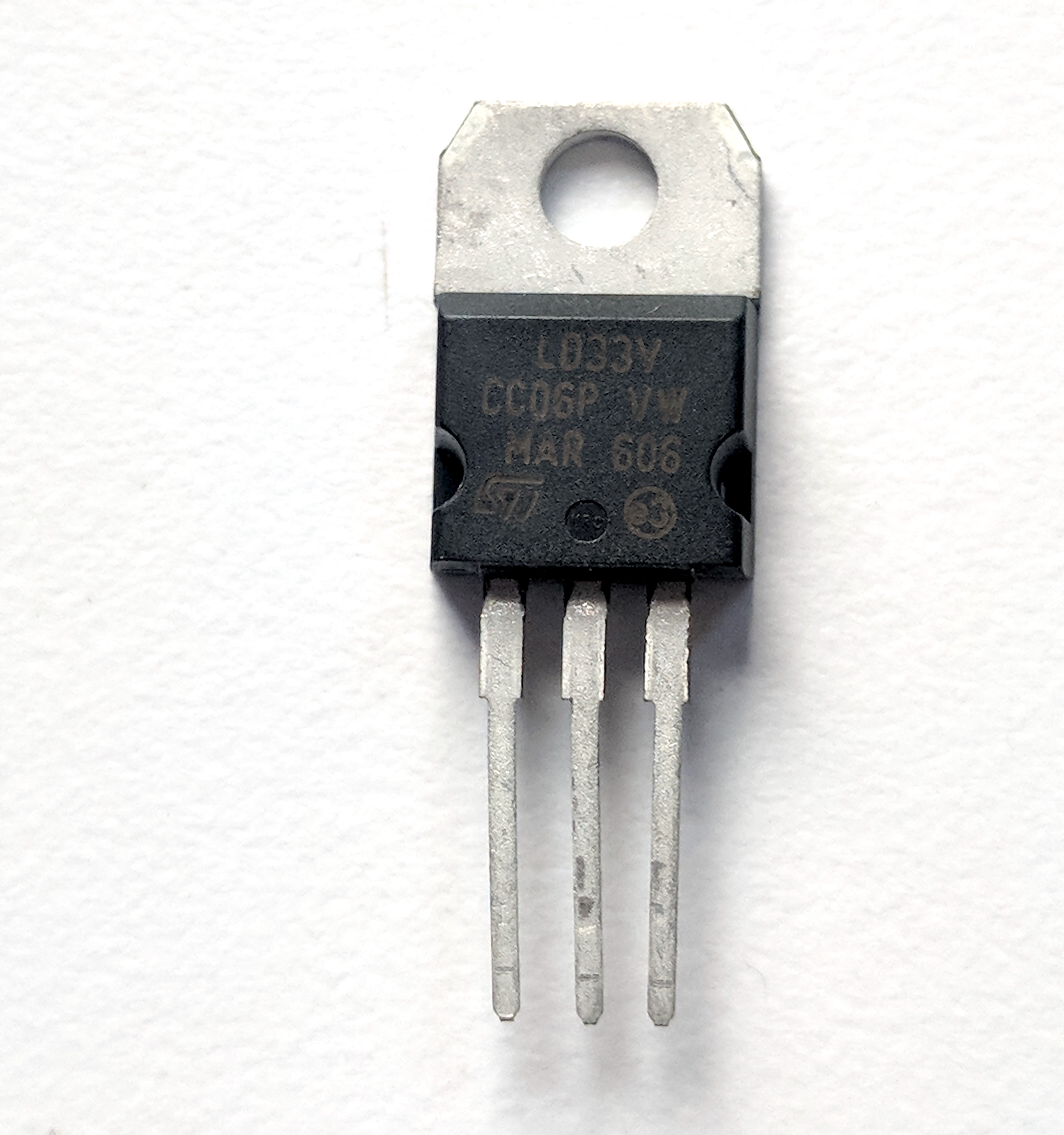
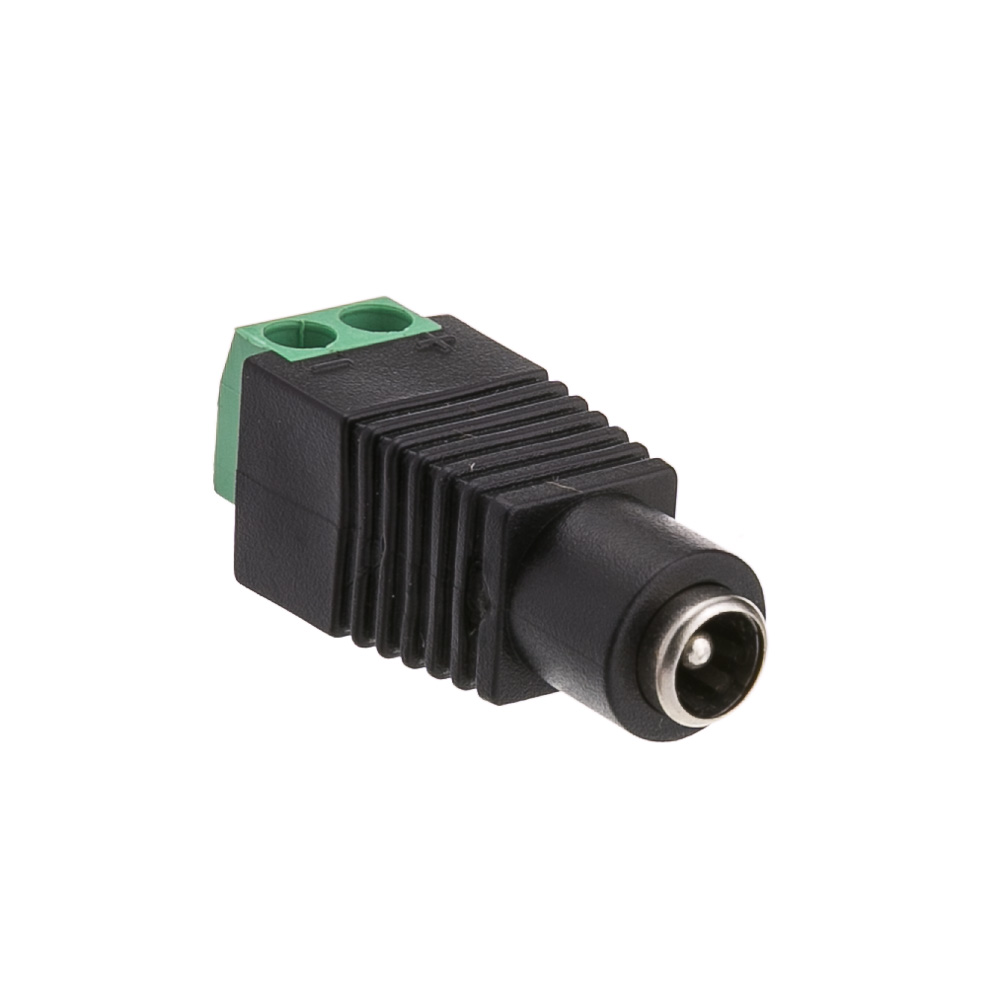
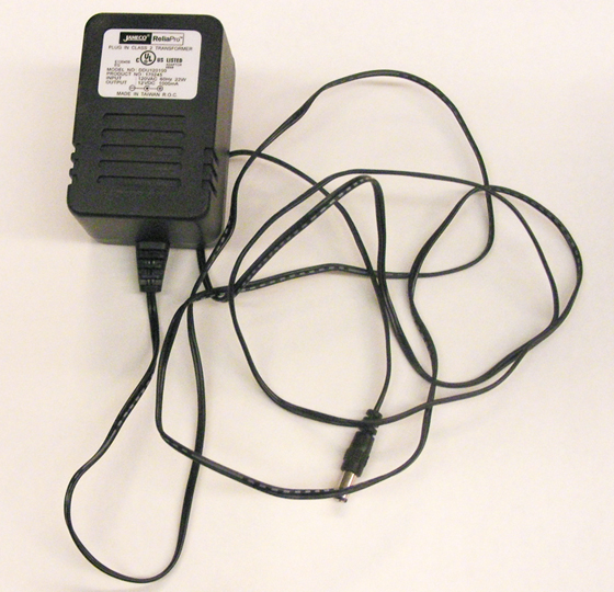
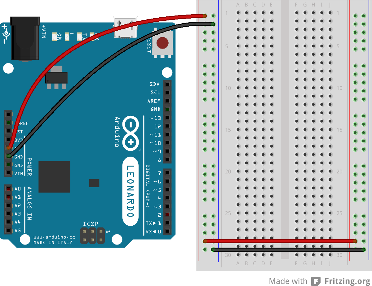
Though you can power most Arduino sensor projects from the USB port of your computer, you may want to make a project that doesn’t attach to your computer. For this you’ll need a power supply. You may have one at home already. If you don’t have one, you can wait until you are working on a project that needs it. You probably won’t need one in the first couple of weeks of the semester.

If your device can run on less than 500 milliamps and 5 or 3.3 volts, you can power it from a USB cable via your Arduino, and a USB AC to DC power adapter like the ones that you use to charge your phone can run the project .

For some projects, you may need more than a v-volt supply. A 12-Volt AC to DC converter that can supply 1000 or more milliamps is a good general supply. Many will already have a 2.1mm x 5.5mm DC barrel jack connector. There are DC barrel jack and plug adapters in the parts BOM that can connect to this type of connector.

Electronics Tool Kit

Used every week.

The shop stocks a full set of electronics tools which you can use. If you plan to do more electronics on your own, there are a few tools you should pick up for yourself, so you’ve always got a reliable set handy. These are common tools, and you can find them at any electronics retailer or hardware store. The ITP Tool List 2020 includes basic hand tools you’ll need if you don’t already have them. It lists several options for each, for comparison.

The electrical tools and hand tools below are ones you’ll use most every week and every project. You probably won’t need a soldering iron and soldering hardware right away, but you’ll use it frequently, from about week 2 or 3. The rest of the tools are less critical, or optional.
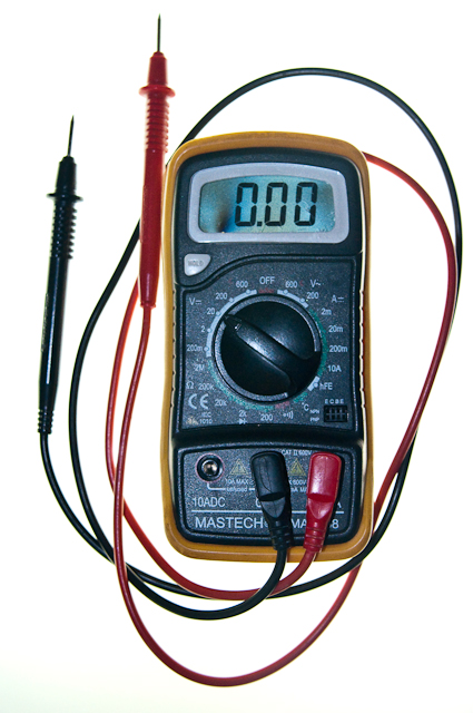
Related video: Basic Tools

Electrical Tools

Used every week. Available for use in the shop.

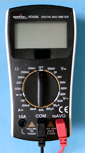
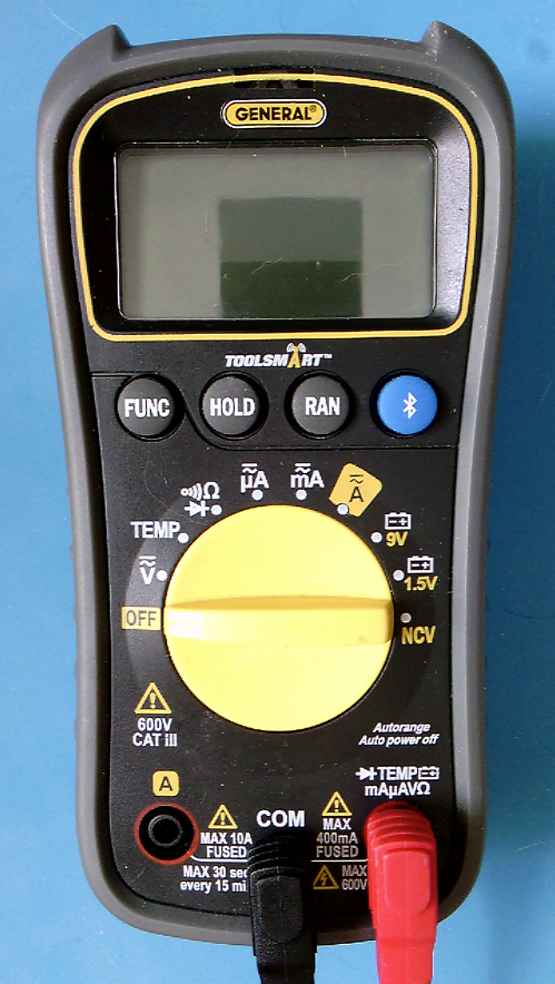
  • Digital Multimeter – You don’t need a fancy multimeter. One that measures voltage, current, continuity, and resistance will do the job.
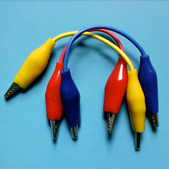
  • Alligator Test Leads – these are wires with clips on the end, handy for when you’ve got components to test that can’t fit in a breadboard and that you don’t want to solder yet.

Hand Tools

Used every week. Available for use in the shop.

You’ll use hand tools frequently in this class. You may have some of these already.

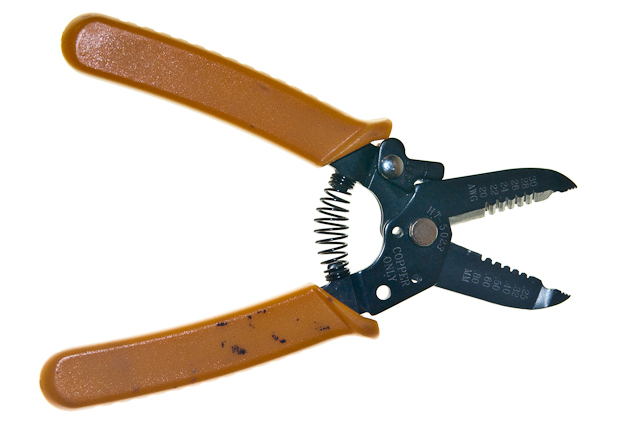
  • Wire Strippers, 20-30AWG – These allow you to strip the insulation from wires. The most common wire you’ll use is 22AWG thickness, so use a stripper that can strip wires in that range.
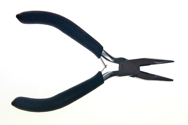
  • Needle Nose Pliers – These are essential, you’ll use them a lot for pulling wires, bending wires, and picking up components.
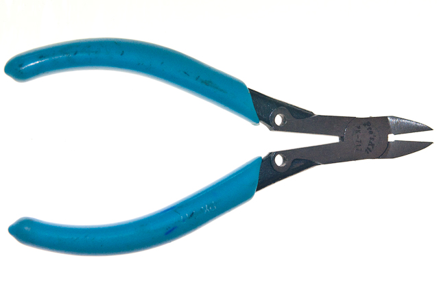
  • Diagonal cutters – These are used for cutting wires and small bits of metal.
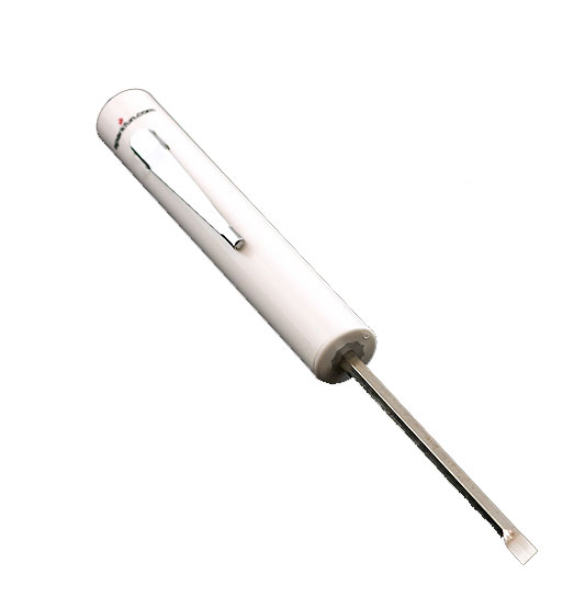
  • Mini Screwdriver – Get a mini screwdriver that has both flat and Philips heads. Many devices have small screws that you need to take out.
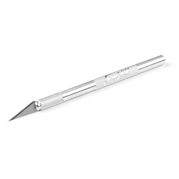
  • Hobby knife -Many people have something like this at home already, but if not, consider getting one. They are effective for cutting cardboard, mat board, and other soft materials.

Personal Protective Equipment (PPE)

Used occasionally. Available for use in the shop.

  • Safety Glasses – You should wear safety glasses when soldering or working with power tools.
  • Fume Extractor – for soldering, it’s a good idea to get a fume extractor, which is a fan and a charcoal filter that pulls the solder smoke away so you don’t breathe it in. They can be expensive, however. The one in the BOM is less expensive and aimed at hobbyists.

Soldering Hardware

Used occasionally. Available for use in the shop.

If you don’t have access to the shop, you might need a set of soldering tools., mostly for soldering header pins on breakout boards.

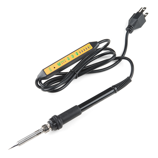
  • Soldering Iron – The most common soldering you’ll do is breakout boards and some connectors. You don’t need a fancy iron, but a relatively fine tip is useful.
  • Extra soldering tip – make sure you get one that matches your iron
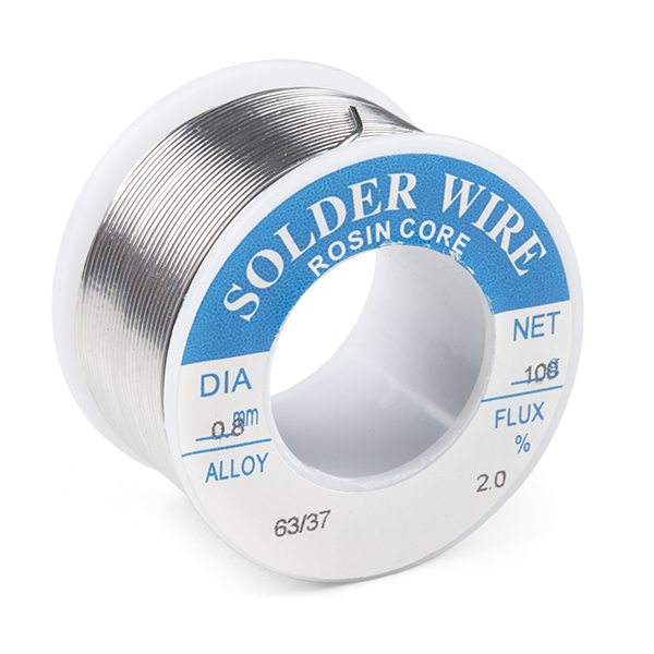
  • Solder – 18-22 AWG lead-free is the recommended choice for this class.
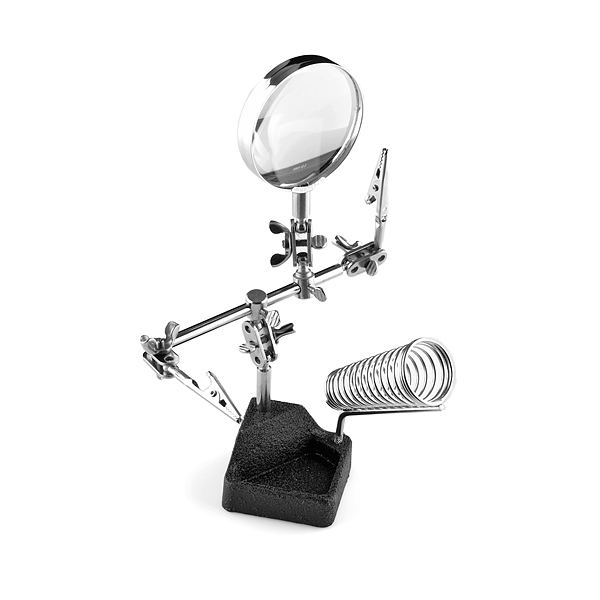
  • Third Hand – You’ll need something to hold the parts that you want to solder while you’re soldering, and this is the most basic tool for the job.
  • Solder Wick. – braided copper that you can use to wick solder away when you make a mistake. Solder and solder wick are expendable, you can only use them once, so you may need more if you solder frequently.
  • Solder Vacuum or Desoldering tool – A desoldering tool is another way to remove solder. You probably don’t need both this and solder wick as a beginner. Nice to have, but not essential.
  • Insulated Silicone Soldering Mat – This keeps your tabletop clean, and it’s also a good insulation so you avoid static discharge on the parts you’re working with. Nice to have, but not essential.
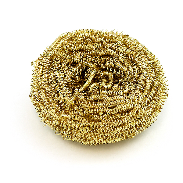
  • Brass Sponge – A tool for cleaning the tip of the iron. Don’t use a wet sponge, as it can rust your tip. Nice to have, but not essential.

Expendables

Optional

These are some materials you might find convenient in some projects.

  • Heat shrink tube – Shrinks down on a wire to make an insulator. Useful to tidy up projects.
  • Electrical tape – a quick insulating material
  • Copper tape – can be handy for making your own switches

Construction Materials

You’ll go through a lot of construction materials in this class. To save money and save the environment, consider reusing materials. Cardboard boxes and used plastic food containers can make great housings for electronic prototypes.  Paper mat board and cardboard can make great housings and control surfaces as well. You will save yourself some money in the process if you do this.  You’re not expected to make polished, production-ready devices in this class, so don’t waste time and money on high-end plastics and metals when you don’t have to.

For more information on parts, see the Suppliers page.

Accelerometers, Gyros, and IMUs: The Basics

Introduction

Inertial Motion Units (IMUs) are sensors that measure movement in multiple axes. Accelerometers measure a changing acceleration on the sensor. They can be used to measure the tilt of the sensor with respect of the Earth, or the force of a hit. They are common in mobile devices and automobiles. Gyrometers measure changing angular motion. They can be used to measure rotation. Magnetometers measure the magnetic force on a sensor. These are usually used to measure the Earth’s gravitational field in order to determine compass heading. IMUs have become increasingly common in microcontroller projects, to the point where they are built into some microcontroller boards like the Arduino 33 IoT and BLE Sense, and the Arduino 101. In this lesson, you’ll learn a few principles of working with these sensors, and see some examples.

What You’ll Need to Know

To get the most out of this lab, you should be familiar with the following concepts and you should install the Arduino IDE on your computer. You can check how to do so in the links below:

Things You’ll Need

Figures 1-4 below show the parts you’ll need for this exercise. Click on any image for a larger view.

Photo of an Arduino Nano 33 IoT module. The USB connector is at the top of the image, and the physical pins are numbered in a U-shape from top left to bottom left, then from bottom right to top right.
Figure 1. Microcontroller. Shown here is an Arduino Nano 33 IoT. An Uno will do for some of the examples here, though.
Photo of flexible jumper wires
Figure 2. Jumper wires.  You can also use pre-cut solid-core jumper wires.
Photo of a solderless breadboard
Figure 3. A solderless breadboard
Photo of an accelerometer, model LIS3DH
Figure 4. An accelerometer. Shown here is an ST Microelectronics LIS3DH accelerometer. Others will be mentioned below.

Orientation, Position, and Degrees of Freedom

“Orientation, or compass heading, is how you determine your direction if you’re level with the earth. If you’ve ever used an analog compass, you know how important it is to keep the compass level in order to get an accurate reading. If you’re not level, you need to know your tilt relative to the earth as well. In navigational terms, your tilt is called your attitude, and there are two major aspects to it: roll and pitch. Roll refers to how you’re tilted side-to-side. Pitch refers to how you’re tilted front-to-back.

“Pitch and roll are only two of six navigational terms used to refer to movement. Pitch, roll, and yaw refer to angular motion around the X, Y, and Z axes. These are called rotations. Surge, sway, and heave refer to linear motion along those same axes. These are called translations.  These are often referred to as six degrees of freedom. Degrees of freedom refer to how many different parameters the sensor is tracking in order to determine your orientation.

“You’ll hear a number of different terms for these sensors. The combination of an accelerometer and gyrometer is sometimes referred to as an inertial measurement unit, or IMU… When an IMU is combined with a magnetometer, the combination is referred to as an attitude and heading reference system, or AHRS. Sometimes they’re also called magnetic, angular rate, and gravity, or MARG, sensors. You’ll also hear them referred to as 6-degree of freedom, or 6-DOF, sensors. There are also 9-DOF sensors that incorporate all three types of sensors. Each axis of measurement is another degree of freedom. [There are] even has 10-DOF sensor[s] that add barometric pressure sensor[s] for determining altitude.”

From Making Things Talk, 3rd edition

Features of an IMU

Whether you’re dealing with an accelerometer, gyrometer, or magentometer, there are a few features you’ll need to consider:

  • Range – IMU sensors come in different ranges of sensitivity.
    • Acceleration is generally measured in meters per second squared (m/s^2) or g’s, which are multiples of the acceleration due to gravity. 1g = 9.8 m/s^2. Accelerometers come in ranges from 2g to 250g and beyond. the force of gravity is 1g, but a human punch can be upwards of 100g
    • Angular motion is measured in degrees per second (dps). Gyro ranges of 125dps to 2000 dps are not uncommon.
    • Magnetic force is measured in Teslas. In most direction applications, the important measurement, however is the relative magnetic field strength on each axis.
  • Number of axes – Almost all IMU sensors can sense their respective properties on multiple axes. Whatever activity you’re measuring, you’ll most likely want to know the acceleration, rotational speed, or magnetic force in horizontal and vertical directions. Most sensors give results for the X, Y, and Z axes. Z is typically perpendicular to the Earth, and the other two are parallel to it, but perpendicular to each other.
  • Electrical Characteristics – as with any electronic sensor, you should pay attention to current consumption and make sure the rated voltage of your IMU is compatible with your microcontroller.
  • Interface – IMUs come with a variety of interfaces. Some provide a changing analog voltage on each axis. Others will provide an I2C or SPI synchronous serial interface. Older IMUs will provide a changing pulse width that corresponds with the changing properties of the sensor. Nowadays, most IMUs are either I2C, SPI, or analog.
  • Extra Features – in addition to the basic physical properties, many IMUs will have additional features, like freefall detection or  tap detection, or additional control features like the ability to set the sensing rate.

For more on choosing an IMU, Sparkfun has an excellent introductory guide.

Most vendors of accelerometer modules do not actually make the sensors themselves, they just put them on a breakout board along with the reference circuit, for convenience. While you might buy your IMU from Sparkfun, Adafruit, Seeed Studio, or Pololu, for example, the chances are the actual sensor is manufactured by another company like Analog Devices, ST Microelectronics, or Bosch. When you shop for a sensor module, check out the manufacturer’s datasheet in addition to the vendor’s tech specs.

Analog IMUs

Analog IMU sensors typically have an output pin for each axis that outputs a range from 0 volts to the sensor’s maximum voltage. Most of them only have one form of sensor (accelerometer, gyrometer, magnetometer). Having multiple pins for each type of sensor would be unweildy.

Since it’s possible to have both positive and negative change in a given sensor’s range, the rest value for each output pin is usually in the middle of the voltage range. You need to understand this in order to read the sensor.

Analog Devices’ ADXL series of accelerometers are useful examples of this kind of sensor. There are two similar models, the ADXL335 and the ADXL377. The former is good for simple range of motion applications, and latter is designed for high-acceleration applications, like crashes, punches, and so forth.  Both operate at 3.3V. Both output analog voltages for X, Y, and Z. Both output their midrange voltage, about 1.65V,  on each axis when it’s at rest (at 0g). The ADXL335 is a +/-3g accelerometer, and the ADXL377 is a +/- 200g accelerometer.  While you’d see a significant change on the ADXL335’s axes when you simply tilt the sensor, you’d see barely any when you simply tilt the ADXL377. Why? Consider the math:

The ADXL335 outputs 0V at -3g, 3.3V at +3g, and 1.65V at 0g. That means that 1g of acceleration changes the analog output by 1/6 of its range. If you’re using analogRead() on an Arduino with a 3.3V analog reference voltage, that means you’ve got a range of about 341 points per g of acceleration (1024 / 6).  When you tilt the accelerometer to 90 degrees, you’re getting +1g on the X or Y axis. That’s a reading of about 682 using analogRead() on an Arduino. When you tilt it 90 degrees the other way, you’re getting -1g on the same axis, or  about 341 using analogRead().

The ADXL377 outputs 0V at -200g, 3.3V at +200g, and 1.65V at 0g. That means 1g of acceleration changes the output by only 1/400 of its range. The same tilting action described above would give you a change from about 510 to 514 using analogRead(),using the same math as above.

This lesson applies whether you’re measuring acceleration, rotation, or magnetic field strength. Make sure to use a sensor that matches the required range otherwise you won’t see much change, particularly with an analog sensor.

Analog Accelerometer Example

Figure 5 shows the schematic for connecting an ADXL335 to an Arduino, and Figures 6 and 7 show the breadboard view for the Uno and the Nano, respectively. For both boards, the accelerometer’s Vcc pin is connected to the voltage bus, and its ground pin is connected to the ground bus. The X axis pin is connected to the Uno’s analog in 2, the Y axis pin is connected to the Uno’s analog in 1, and the Z axis pin is connected to the Uno’s analog in 0.

Other analog IMUs are wired similarly.

Schematic view of an Arduino connected to an ADXL3xx accelerometer.
Figure 5. Schematic view of an Arduino connected to an ADXL3xx accelerometer. The accelerometer’s Vcc pin is connected to 3.3V on the Arduino, and its ground pin is connected to ground . The X axis pin is connected to the Arduino’s analog in 2, the Y axis pin is connected to the Arduino’s analog in 1, and the Z axis pin is connected to the Arduino’s analog in 0.
Breadboard view of an Arduino Uno connected to an ADXL3xx accelerometer.
Figure 6. Breadboard view of an Arduino Uno connected to an ADXL3xx accelerometer. The Uno is connected to a breadboard, with its 3.3V pin (not 5V as in other examples) connected to the voltage bus and its ground pin connected to the ground bus. The accelerometer is connected to six rows in the left center section of the breadboard beside the Uno.
Breadboard view of an Arduino Nano connected to an ADXL3xx accelerometer.
Figure 7. Breadboard view of an Arduino Nano connected to an ADXL3xx accelerometer. The Nano is connected as usual, straddling the first fifteen rows of the breadboard with the USB connector facing up. Voltage (physical pin 2) is connected to the breadboard’s voltage bus, and ground (physical pin 14) is connected to the breadboard’s ground bus. The accelerometer is connected to six rows in the left center section of the board below the pushbutton.

The code below will read the accelerometer and print out the values of the three axes:

void setup() {
  Serial.begin(9600);
}

void loop() {
  int xAxis = analogRead(A2); // Xout pin of accelerometer
  Serial.print(xAxis);

  int yAxis = analogRead(A1); // Yout pin of accelerometer
  Serial.print(",");
  Serial.print(yAxis);

  int zAxis = analogRead(A0); // Zout pin of accelerometer
  Serial.print(",");
  Serial.println(zAxis);
}

Digital IMUs

Digital IMUs output a digital data stream via a serial interface, typically SPI or I2C. Unlike analog IMUs, these sensors can be configured digitally as well. Most support changing the sensitivity and the sampling rate, and some allow you to turn on and off features like tap detection or freefall detection.

Many digital IMUs are truly IMUs, in that they combine multiple sensors: accelerometer/gyrometer, accelerometer/gyrometer/magnetometer, and so forth.

Another advantage of digital IMUs is that they tend to convert their sensor readings at a higher level of resolution than a microcontroller’s analog input. While a microcontroller’s ADC is typically 10-bit (0-1023), many digital IMUs read their sensors into a 16-bit or even 32-bit result. This gives you greater sensitivity than an analog IMU.

Digital Accelerometer Example

Figure 8 shows the schematic for connecting a LIS3DH accelerometer to an Arduino, and Figures 9 and 10 show the breadboard view for the Uno and the Nano, respectively. For both the Uno and the nano, the accelerometer’s Vcc pin is connected to the voltage bus, and its ground pin is connected to the ground bus. The SDA pin is connected to the microcontroller’s analog in 4, the SCL pin is connected to the microcontroller’s analog in 5 , and the SDO is connected to the ground bus. Other digital IMUs are wired similarly.

Schematic view of an Arduino Nano connected to an LIS3DH accelerometer
Figure 8. Schematic view of an Arduino connected to an LIS3DH accelerometer. The accelerometer’s Vcc pin is connected to 3.3V on the Arduino, and its ground pin is connected to the Arduino’s ground. The SDA pin is connected to the Uno’s analog in 4, the SCL pin is connected to the Uno’s analog in 5, and the SDO is connected to ground.
Breadboard view of an Arduino Uno connected to an LIS3DH accelerometer
Figure 9. Breadboard view of an Arduino Uno connected to an LIS3DH accelerometer. The Uno is connected to a breadboard, with its 3.3V pin (not 5V as in other examples) connected to the voltage bus and its ground pin connected to the ground bus. The accelerometer is straddling the center of the board.

Breadboard view of an Arduino Nano connected to an LIS3DH accelerometer
Figure 10. Breadboard view of an Arduino Nano connected to an LIS3DH accelerometer. The Nano is connected as usual, straddling the first fifteen rows of the breadboard with the USB connector facing up. Voltage (physical pin 2) is connected to the breadboard’s voltage bus, and ground (physical pin 14) is connected to the breadboard’s ground bus. The accelerometer is straddling the center of the board below the Nano.

The following code will read the accelerometer and print out the acceleration on each axis in g’s. This accelerometer has a 14-bit range of sensitivity. The code below configures the accelerometer for a 2g range, and converts the 14-bit range to -2 to 2g. This is a simplification of one of the LIS3DH library examples by Kevin Townsend.  It uses Adafruit’s LIS3DH library, but will work for any breakout board for the LIS3DH. It’s been tested with both Sparkfun’s and Adafruit’s boards for this sensor:

#include "Wire.h"
#include "Adafruit_LIS3DH.h"

Adafruit_LIS3DH accelerometer = Adafruit_LIS3DH();

void setup() {
  Serial.begin(9600);
  while (!Serial);
  if (! accelerometer.begin(0x18)) {
    Serial.println("Couldn't start accelerometer. Check wiring.");
    while (true);     // stop here and do nothing
  }
  accelerometer.setRange(LIS3DH_RANGE_8_G);   // 2, 4, 8 or 16 G
}

void loop() {
  accelerometer.read();      // get X, Y, and Z data
  // Then print out the raw data
  Serial.print(convertReading(accelerometer.x));
  Serial.print(",");
  Serial.print(convertReading(accelerometer.y));
  Serial.print(",");
  Serial.println(convertReading(accelerometer.z));
}

// convert reading to a floating point number in G's:
float convertReading(int reading) {
  float divisor = 2 <<; (13 - accelerometer.getRange());
  float result = (float)reading / divisor;
  return result;
}

Here’s a link to some more examples for the LIS3DH which work with either Adafruit’s or Sparkfun’s LIS3DH board.


Built-in IMUs

Some microcontroller boards, like the Nano 33 IoT and Nano 33 BLE sense and the 101, have built-in IMUs. These are digital IMUs, and they’re connected to either the SPI or  I2C bus of the microcontroller. This means you might have conflicts if you’re using them along with an external I2C or SPI sensor. For example, when you’re using them as an I2C sensor, you need to know their I2C address so you don’t try to use another I2C sensor with the same address.

Most built-in IMUs will come with a board-specific library, like the 101’s CurieBLE or the Nano 33 IoT’s Arduino_LSM6DS3 library. Otherwise, they will be identical to the digital IMUs, so even with a built-in accelerometer, you can get more information from the accelerometer’s datasheet or the library’s header files.

Nano 33 IoT Built-In IMU Example

The LSM6DS3 IMU that’s on the Nano 33 IoT is an accelerometer/gyrometer combination. You can get both acceleration and rotation from it. The IMU is built into the board, so there is no additional circuit.

The code example below will read the accelerometer in g’s and the gyrometer in degrees per second and print them both out:

#include "Arduino_LSM6DS3.h"

void setup() {
  Serial.begin(9600);
  // start the IMU:
  if (!IMU.begin()) {
    Serial.println("Failed to initialize IMU");
    // stop here if you can't access the IMU:
    while (true);
  }
}

void loop() {
  // values for acceleration and rotation:
  float xAcc, yAcc, zAcc;
  float xGyro, yGyro, zGyro;

  // if both accelerometer and gyrometer are ready to be read:
  if (IMU.accelerationAvailable() &&
      IMU.gyroscopeAvailable()) {
    // read accelerometer and gyrometer:
    IMU.readAcceleration(xAcc, yAcc, zAcc);

    // print the results:
    IMU.readGyroscope(xGyro, yGyro, zGyro);
    Serial.print(xAcc);
    Serial.print(",");
    Serial.print(yAcc);
    Serial.print(",");
    Serial.print(zAcc);
    Serial.print(",");
    Serial.print(xGyro);
    Serial.print(",");
    Serial.print(yGyro);
    Serial.print(",");
    Serial.println(zGyro);
  }
}

What To Look For in an IMU Library

Different vendors will generally write their own libraries for the IMUs they sell. When you’re looking at a given vendor’s product, take a look at the properties of the sensor in the vendor’s datasheet, and the list of public functions in the library’s API. Does the library give you the functions of the sensor that you need? If the sensor supports multiple sensing ranges, does the library give you access to setting and getting the range? Is it well-documented, and well-commented? Are there simple, clear, well-commented examples?

For example, both Sparkfun and Adafruit make breakout boards for the LIS3SH accelerometer. This accelerometer is typical for a digital accelerometer; it’s got I2C and SPI interfaces, operates at 3.3V, and has a range of acceleration sensitivity, from 2g to 16g. The Adafruit getting started guide and the Sparkfun getting started guide get you up and running, but neither provides a summary of all the functions in their libraries. To see that, you need to look at the header files for each library. Adafruit’s header file is exhaustively commented, which can take time to get through. The key public functions start around line 344. It relies on their Unified Sensor library, which adds some complexity, but there are some nice additions, like the click functionality that the accelerometer supports. Sparkfun’s header file is less thoroughly commented, but shorter. The key public functions start about line 116.  If you only need the basic acceleration functions, it’s easier to use because of less dependency on other libraries. Both are good libraries, though, and you should choose based on the features you want and how easy you find each to use.

You could use either library with either breakout board, but there is one catch: when you’re using the board’s I2C synchronous serial interface, you have to pay attention to the address you use in the the Adafruit board defaults to a different I2C address than the Sparkfun one. SparkFun defaults to 0x19, while Adafruit defaults to 0x18. In I2C mode, the SDO pin switches the I2C default address between 0x18 and 0x19. Taking this pin HIGH sets the address to 0x19, while taking it LOW sets it to 0x18, so by changing this pin, you can choose which library you prefer. Both libraries also have the ability to change the address they use for the accelerometer as well.

Determining Orientation

Determining orientation from an IMU takes some advanced math. Fortunately, there are a few algorithms for doing it. In 2010, Sebastian Madgwick developed and published a more efficient set of algorithms for determining yaw, pitch, and roll using the data from IMU sensors. Helena Bisby converted Madgwick’s algorithms into a Madgwick library for Arduino, improved upon by Paul Stoffregen and members of the Arduino staff. Though it was originally written for the Arduino 101, it can work with any IMU as long as you know the IMU’s sample rate and sensitivity ranges. Here’s an example that uses the Madgwick library and the Nano 33 IoT’s LSM6DS3 IMU to determine heading, pitch, and roll:

#include "Arduino_LSM6DS3.h"
#include "MadgwickAHRS.h"

// initialize a Madgwick filter:
Madgwick filter;
// sensor's sample rate is fixed at 104 Hz:
const float sensorRate = 104.00;

void setup() {
  Serial.begin(9600);
  // attempt to start the IMU:
  if (!IMU.begin()) {
    Serial.println("Failed to initialize IMU");
    // stop here if you can't access the IMU:
    while (true);
  }
  // start the filter to run at the sample rate:
  filter.begin(sensorRate);
}

void loop() {
  // values for acceleration and rotation:
  float xAcc, yAcc, zAcc;
  float xGyro, yGyro, zGyro;

  // values for orientation:
  float roll, pitch, heading;
  // check if the IMU is ready to read:
  if (IMU.accelerationAvailable() &&
      IMU.gyroscopeAvailable()) {
    // read accelerometer &and gyrometer:
    IMU.readAcceleration(xAcc, yAcc, zAcc);
    IMU.readGyroscope(xGyro, yGyro, zGyro);

    // update the filter, which computes orientation:
    filter.updateIMU(xGyro, yGyro, zGyro, xAcc, yAcc, zAcc);

    // print the heading, pitch and roll
    roll = filter.getRoll();
    pitch = filter.getPitch();
    heading = filter.getYaw();
    Serial.print("Orientation: ");
    Serial.print(heading);
    Serial.print(" ");
    Serial.print(pitch);
    Serial.print(" ");
    Serial.println(roll);
  }
}

Conclusion

There are dozens of accelerometers, gyrometers, and IMUs on the market, and as they become more ubiquitous in electronic devices, they continue to get smaller, cheaper, and more power-efficient. The principles laid out here should give you a basis for getting to know new ones as needed.

Breadboard Layouts

We use a few different microcontroller boards in this class over the years, but for each one, there is a standard way we lay out the breadboard. This page details those layouts. In any lab exercise, you can assume the microcontroller and breadboard are laid out in this way, depending on the controller you are using. Figures 1, 2, and 3 show the layouts of an Arduino Nano 33 IoT, an Arduino Uno, an Arduino MKR.

Nano Layout

Arduino Nano on a breadboard.
Figure 1. Breadboard view of an Arduino Nano on a breadboard

Figure 1. An Arduino Nano mounted on a solderless breadboard. The Nano is mounted at the top of the breadboard, straddling the center divide, with its USB connector facing up. The top pins of the Nano are in row 1 of the breadboard.

The Nano, like all Dual-Inline Package (DIP) modules, has its physical pins numbered in a U shape, from top left to bottom left, to bottom right to top right. The Nano’s 3.3V pin (physical pin 2) is connected to the left side red column of the breadboard. The Nano’s GND pin (physical pin 14) is connected to the left side black column.

These columns on the side of a breadboard are commonly called the buses. The red line is the voltage bus, and the black or blue line is the ground bus. The blue columns (ground buses) are connected together at the bottom of the breadboard with a black wire. The red columns (voltage buses) are connected together at the bottom of the breadboard with a red wire.

Uno Layout

An Arduino Uno on the left connected to a solderless breadboard, right.
Figure 2. Breadboard drawing of an Arduino Uno on the left connected to a solderless breadboard on the right

Figure 2. An Arduino Uno on the left connected to a solderless breadboard, right. The Uno’s 5V output hole is connected to the red column of holes on the far left side of the breadboard. The Uno’s ground hole is connected to the blue column on the left of the board. The red and blue columns on the left of the breadboard are connected to the red and blue columns on the right side of the breadboard with red and black wires, respectively. These columns on the side of a breadboard are commonly called the buses. The red line is the voltage bus, and the black or blue line is the ground bus.


MKR Layout

An Arduino MKR series microcontroller mounted on a breadboard
Figure 3. Breadboard view of an Arduino MKR series microcontroller mounted on a breadboard

Figure 3. An Arduino MKR series board mounted on a solderless breadboard. The MKR is mounted at the top of the breadboard, straddling the center divide, with its USB connector facing up. The top pins of the MKR are in row 1 of the breadboard.

The Nano, like all Dual-Inline Package (DIP) modules, has its physical pins numbered in a U shape, from top left to bottom left, to bottom right to top right. The MKR’s Vcc pin (physical pin 26) is connnected to the right side red column of the breadboard. The MKR’s GND pin (physical pin 25) is connected to the right side black column. These columns on the side of a breadboard are commonly called the buses. The red line is the voltage bus, and the black or blue line is the ground bus.

The blue columns (ground buses) are connected together at the bottom of the breadboard with a black wire. The red columns (voltage buses) are connected together at the bottom of the breadboard with a red wire.


Videos: Actuators

The videos linked from this page describe specific forms of output, or actuators.

Intro to programmable LEDs: NeoPixels (worldSemi WS2812):

Color spaces in programmable LEDS:

Picking a Microcontroller

by Tom Igoe, August 2016
updated June 202
3

Introduction

With a wide variety of Arduino and Arduino-compatible options on the market, students often ask “which is the best controller for me to get?” What follows is a guide how to decide what to choose. This is by no means an exhaustive list, it only includes boards I use regularly enough to recommend.

The lab exercises for this class were originally written for the Arduino Uno. Currently we teach it with the Arduino Nano 33 IoT, for reasons explained below.

The things you should consider in picking a controller, other than price:

  • Is this controller compatible with my other components?
    • Does it operate on the same voltage range?
    • Does it have the correct interface (e.g. asynchronous serial, I2C, SPI)?
    • Is it programmable with the tools I am using and any existing code I am using?
  • What  physical inputs and outputs do I need?
  • With what other devices does it need to communicate?
    • What protocols will they use (e.g. WiFi, Bluetooth, USB, etc)?
    • What aspects of the project can be handled by those other devices?
  • Is the form factor one I can work with?

The processor at the core of the Uno, Atmel’s ATMega328, is an 8-bit microcontroller. The ATMega328 is one of the few processors that still comes in a breadboard-friendly DIP package, so you can even build your own Uno-compatible circuit on a breadboard if you want to save money. In projects where you’re using multiple controllers, the DIY breadboard option is a smart choice. However, it’s not a task for you if you aren’t yet comfortable building circuits and reading schematics.

Nowadays, 32-bit microcontrollers are available for about the same price or cheaper than 8-bit controllers. The Arduino Nano series and MKR series are mostly 32-bit processors (the Nano Every is still 8-bit) that can do all that the original Uno can do and more. These newer controllers have more processing power and memory for your program than the Uno and other 8-bit controllers, and with the various connectivity options (WiFi, Bluetooth) that these boards offer, you’ve got more room to grow. If you’re buying your first controller, your best choice is probably one of the 32-bit controllers. The Nano line and the MKR line are the ones I currently use the most.

3.3V? 5V? What’s the difference?

1.7V, of course (a little electrical humor).

The Arduino Uno and the boards that came before it operated on 5 volts DC. However many newer controllers, including all the ones here,  and the embedded Linux boards like the BeagleBone and the Raspberry Pi, operate on 3.3 volts instead. Many older components, like the Sharp IR rangers that are popular in physical computing, operate on 5 volts, and many newer ones operate on 3.3 volts. Because of this change, you often need to adjust the voltage output of one component before it goes into another component. This is called level shifting. It’s a common technique you learn how to deal with when you work with many different components.

I Need A Lot of Input and Output…

Many physical computing projects need lots of input and output connections to read lots of sensors. There are lots of strategies for handling this. Many of the most common strategies are described in chapter 14 of Physical Computing: Sensing and Controlling the Physical World by Dan O’Sullivan and Tom Igoe. Although that book describes processors other than the Arduino, the circuits and techniques described work well with Arduino-compatible boards.

If you just want a single board with a lot of pins, consider the Arduino Due.   The Due has an Atmel SAM3X8E ARM Cortex-M3 processor, which is a more powerful version of the processor than the M0 in the MKR boards. This, or the strategies in Physical Computing, are probably the best option for multiple I/O for beginners.

If you’re feeling more advanced and want another approach, consider building your project with multiple processors. You can build your own Uno variant on a breadboard, or you can use the even smaller ATTiny84 and ATTiny85 controllers. These controllers have only a few I/O pins, but they are a couple of dollars each, and David Mellis has an excellent guide to programming them. You can link several of them together in one circuit and have each one control a handful of your I/O pins, then use one of the other processors mentioned here as a main controller.

Connectivity

Increasingly, projects need not just basic input and output, but also WiFi, Bluetooth, USB, or some other form of connectivity. This is where the more modern boards outshine the Uno and derivatives. Bluetooth, WiFi, and USB are pretty easy to get on a variety of boards. Other radio types are less common, but there’s a board for pretty much every form of connectivity.

Nano

The Nano family is a good, inexpensive starting place for beginners, with lots of room to grow. The Nano Every is thoroughly compatible with the Uno’s architecture for a lower price. It operates on 5 volts, just like the Uno. The Nano 33 IoT is a 3.3V board, with lots of extra features. It has the same processor as the MKR series, the SAMD21 Cortex M0+ ARM processor, and has a Bluetooth and WiFi radio on board, at a lower price than the MKR line.  At the top of the line, the Nano 33 BLE and BLE Sense and the Nano RP2040 Connect have enough processor power to run TinyML machine learning models as well.

Code you’ve written for the Uno will also run on the Nanos as well, but you’ll need to pay attention to which pins your external components are connected to, since the layout is not the same as the Uno. All of the Nanos except the Every are 3.3V boards, meaning that the default voltage is 3.3 volts, not 5 volts. This can present some challenges when dealing with sensors that operate on 5 volts, though nowadays most sensors are 3.3-volt compatible.

MKR

The MKR family are handy when you need advanced connectivity features.They have the same SAMD Cortex M0+ as the Nano 33 IoT, and a built-in rechargeable battery connector and charging circuit. Like most of the Nanos, the MKRs are 3.3V boards. There are several boards in the MKR line for different connectivity needs: The MKRZero has a built-in MicroSD card. The MKR1000 and MKR1010 are WiFi boards; the MKR1010 has Bluetooth as well. The MKR1300 and MKR1310 have LoRa and LoRaWAN connectivuty. The MKR1400 has a GSM radio, and the MKR1500 has a NB IoT 3G radio. In addition, there are several special purpose shields for the MKR boards.

Caveat: be wary of cheap derivatives, clones, and counterfeits of these boards. There are a number of very good derivatives that offer extra features, or different layouts. There are also a number of derivatives and clones that try to look the same, but use lower quality components or spend less time on inspecting assembled boards. We see a few broken projects every year that are due to a clone board failing.  Many of the vendors linked from this page sell their own Arduino-compatible variants that are reputable, if you want to look for derivatives.

Feather

Adafruit’s Feather M0 boards are also good DIP-format boards. They use the same processor, Atmel’s CortexM0+, they also use the DIP package, and they come in a variety of special-purpose variations. The basic Feather M0 Proto board has just the processor, it’s like a MKR1000 without the Wifi. The Feather Adalogger M0 is the same thing with a built-in SD card. The Feathers also have a built-in LiPo battery charger.

With one of the boards above, you can do everything covered in the labs for this class, with a faster and more capable processor than the Uno. Everything that follows is for readers who are already comfortable with microcontrollers, and looking for more info for advanced projects. For more information, see the comparison chart and vendors at the bottom of this page.

ESP

You could also consider Espressif’s processors, if you need lots of processors connected wirelessly. They’re not as inexpensive as the ATTiny processors, but they have built-in WiFi. Espressif’s ESP8266 processor is a very inexpensive 32-bit processor with WiFi built in. It’s very popular when you’re building projects that need lots of WiFi devices. THE ESP boards have relatively little I/O, however,  and only one analog in that can only read a 1-volt range. So the lower cost is often lost in extra components to add I/O.  The Feather Huzzah ESP8266 is a good implementation of the ESP8266, as is Spark Fun’s ESP8266 Thing Dev board. Many other vendors sell their own version of the ESP8266 board, but these are the two that I’ve used which are simplest for relative beginners to use. The ESP8266 WiFi libraries are based on the Arduino WiFi101 libraries, so code is relatively compatible with the MKR1000. The ESP32 is an upgraded version of the ESP8266.

The ESP8266 boards can also run other languages. There’s a port of JavaScript, a MicroPython version, and Lua version that are relatively mature, and others still in development. Watch the ESP repositories for updates.

The ESP8266 boards are not great for the absolute beginner, but they’re relatively easy for intermediate users, and handy when you need a lot of processors networked inexpensively.

Can I Program it in Python/JavaScript?

Yes, but there are limitations. There are microcontrollers on the market that you can program with scripting languages like Python and JavaScript. The Espruino is a good version of JavaScript for microcontrollers, and the MicroPython board does the same for Python. The BBC Micro:Bit runs both. The Espruino JavaScript engine is available for the ESP8266 as well. The RP2040 Connect and some of the Feathers run Python as well.

Although these scripting engines seem enticing for microcontroller use, they come at a cost. Scripting engines can never run your code as fast as compiled code, and sometimes the timing can be inconsistent, because the engine’s cleaning up memory and not listening to your I/O pins. Any good programming tool needs a good framework for building libraries as well. When you’re looking at new tools like this, check what libraries are available, and what the framework for building libraries looks like, and how many programmers are using it. Also consider that any scripting language on a microcontroller means that your source code, not the compiled binary program, is present on the processor itself. This is no big deal for hobbyists, but is a potential security risk for commercial products.

What About Embedded Linux?

There are a number of different embedded Linux processors on the market now that are in the same price range as microcontroller boards. The Raspberry Pi and the BeagleBone Green Wireless are excellent examples of this, and good products. These boards are getting more capable all the time. Many of the Processing and P5.js/node.js examples for this class run on the Raspberry Pi 2 and 3, for example, or the BeagleBone Green Wireless.

For this intro to physical computing class, they are overkill, however, because they require you to learn how an embedded operating system works in addition to the electronics, programming, and physical interaction design we’re already covering. It’s not uncommon to combine a microcontroller with an embedded linux processor, with the former handling physical I/O and the latter handling media control or network communication. The two communicate via asynchronous serial, just like your laptop and your microcontroller will do in the serial labs in this class.

For the purposes of this class, you’re welcome to explore the embedded Linux boards independently once you’ve shown mastery of the material covered in class. Your projects will be evaluated mostly on how well they demonstrate good physical interaction design, however.

Where To Get Boards

The Arduino boards mentioned here are carried by the Arduino online store as well as many of the vendors mentioned here: Adafruit, Spark Fun, Seeed Studio, and Digikey are the vendors I use most frequently. For Seeed Studio products in the US, Digikey is a useful reseller. It’s worth comparing them all for pricing, though the differences are not usually large.

Lab: I2C Communication With An Infrared Temperature Sensor

In this lab, you’ll see synchronous serial communication in action using the Inter-integrated Circuit (I2C) protocol. You’ll communicate with an infrared temperature sensor chip from a microcontroller in order to read the temperature of an object in front of the sensor.

Introduction

In this lab, you’ll see synchronous serial communication in action using the Inter-integrated Circuit (I2C) protocol. You’ll communicate with an infrared temperature sensor chip from a microcontroller in order to read the temperature of an object in front of the sensor.

Related videos: Intro to Synchronous Serial, I2C

What You’ll Need to Know

To get the most out of this Lab, you should be familiar with the basics of programming an Arduino microcontroller. If you’re not, review the Digital Input and Output Lab, and perhaps the Getting Started with Arduino guide. You should also understand asynchronous serial communication and how it differs from synchronous serial communication.

Things You’ll Need

Figure 1-3 are the parts that  you need for this lab.

Three 22AWG solid core hookup wires. Each is about 6cm long. The top one is black; the middle one is red; the bottom one is blue. All three have stripped ends, approximately 4 to 5mm on each end.
Figure 1. 22AWG solid core hookup wires.
Photo of an Arduino Nano 33 IoT module. The USB connector is at the top of the image, and the physical pins are numbered in a U-shape from top left to bottom left, then from bottom right to top right.
Figure 2. Arduino Nano 33 IoT
A TMP007 Temperature sensor module. There are 7 pins along the bottom, labeled VCC, GND, SDA, SCL, Alert, AD1, and AD0 (left to right)
Figure 3. A TMP007 Temperature sensor module.
A photo of a short solderless breadboard with two rows of holes along each side. There are no components mounted on the board. The board is oriented sideways so that the long rows of holes are on the top and bottom of the image.
Figure 4. A short solderless breadboard.

Connect the temperature sensor

The temperature sensor used in this lab,  a Texas Instruments TMP007, is an integrated circuit (IC) that can read the temperature of an object placed in front of it. Connect the sensor’s power and ground connections and the connections for clock and serial data as shown in Figure 5-7. For the Arduino UNO board and Nano boards, the I2C pins are fixed A4(SDA) and A5(SCL):

Schematic view of an Arduino attached to a TMP007 temperature sensor. The TMP007 temperature sensor has 7 pins, and when the sensor is positioned with the pins on the bottom and pointing away from you, the pins are labeled VCC, Ground, SDA, SCL, Alert, AD1, and AD0. The sensor's VCC and ground pins (pins 1 and 2) are connected to the Aruino's 5V and GND pins, respectively. The SCL pin (pin 4) is connected to the Arduino's A4 input and the Alert pin (pin 5) is connected to the A5 input.
Figure 4. Schematic view of an Arduino attached to a TMP007 temperature sensor.
Schematic view of an Arduino attached to a TMP007 temperature sensor. The TMP007 temperature sensor has 7 pins, and when the sensor is positioned with the pins on the bottom and pointing away from you, the pins are labeled VCC, Ground, SDA, SCL, Alert, AD1, and AD0. The sensor's VCC and ground pins (pins 1 and 2) are connected to the Aruino's 5V and GND pins, respectively. The SCL pin (pin 4) is connected to the Arduino's A4 input and the Alert pin (pin 5) is connected to the A5 input.
Figure 5. Schematic view of an Arduino attached to a TMP007 temperature sensor.
An Arduino Nano attached to a TMP007 temperature sensor. The TMP007 temperature sensor has 7 pins, and when the sensor is positioned with the pins on the left hand side of the board the pins are labeled VCC, Ground, SDA, SCL, Alert, AD1, and AD0. The sensor's VCC and ground pins (pins 1 and 2) are connected to the Arduino's 3.3V (pin 2) and GND (pin 14) pins, respectively. The sensor's SDA pin (pin 3) is connected to the Arduino's A4 input (pin 8) and the sensor's SCL pin (pin 4) is connected to the Arduino's A5 input (pin 9).
Figure 6. An Arduino Nano attached to a TMP007 temperature sensor. The TMP007 temperature sensor has 7 pins, and when the sensor is positioned with the pins on the left hand side of the board the pins are labeled VCC, Ground, SDA, SCL, Alert, AD1, and AD0. The sensor’s VCC and ground pins (pins 1 and 2) are connected to the Arduino’s 3.3V (pin 2) and GND (pin 14) pins, respectively. The sensor’s SDA pin (pin 3) is connected to the Arduino’s A4 input (pin 8) and the sensor’s SCL pin (pin 4) is connected to the Arduino’s A5 input (pin 9).

The circuit is now complete, and you’re ready to write a program to control it. One of the advantages of the I2C synchronous serial protocol (as opposed to the SPI protocol) is that you only ever need two wires for communication to one or multiple devices.

How the Temperature Sensor Works

I2C devices exchange bits of data whenever the shared clock signal changes.  Controller and peripheral devices both send bits of data when the clock changes from low to high (called the rising edge of the clock). Unlike with SPI, they cannot send data at the same time.

The TMP007 has a series of memory registers that control its function. You can write to or read from these registers using I2C communication from your microcontroller. Some of these registers are writable by the controller so that you can configure the sensor. For example, you can set its I2C address, set the sensitivity of the sensor, and so forth. Some registers are configuration registers, and by writing to them, you configure the chip. For example, you can set lower and upper limits of temperature sensitivity. Other memory registers are read-only. For example, when the sensor has read the temperature of an object, it will store the result in a register that you can read from the controller. The details of the chip’s registers can be found in the TMP007 datasheet, in the “Register Maps” section, page 26.

I2C devices exchange data in 7-bit chunks, using an eighth bit to signal if you’re reading or writing by the controller or for acknowledgement of data received. To get the temperature from the TMP007, your controller device sends the sensor’s address (a 7-bit number) followed by a single bit indicating whether you want to read data or write data (1 for read, 0 for write). Then you send the memory register that you want to read from or write to. For example, as shown in Figure 7, the object temperature is stored in memory register 01 of the TMP007. To get the temperature, you send:

I2C data. I2C communication. The first 3 bytes are messages from the controller to the peripheral. The first byte is a one followed by 7 zeros. The first 7 bits in the byte are for the peripheral at address 0x40 and the last bit indicates this is a write command. The second byte is 6 zeros, a one, and a zero. The first 7 bits in the byte indicates this is to read register 0x01 and the last bit is an acknowledgement from the device. The third byte is a one, 6 zeros, and a one. The first 7 bytes again are for the peripheral at address 0x40 and the last bit indicates this is a read command. The final 2 bytes are messages from the peripheral to the controller. The first byte is for 6 zero bits, a one, and a zero. The first 7 bits are the data in register 0x01 and the last bit is an acknowledgement from the device. The second byte is 6 zero bits and 2 ones. The first 7 bits are again data in the register 0x01 and the last bit is a signal from the device that the message is complete.
Figure 7. I2C data

To use I2C communication on an Arduino microcontroller, you use the Wire library, which is built into the Arduino IDE. You can find Arduino-compatible libraries for many devices that use the Wire library, but never expose it directly in their APIs. Adafruit’s TMP007 library is typical of this style of library. The library’s readObjTempC() command sends a write command to start a temperature reading of the object in front of the sensor, then sends a read command to read the appropriate temperature register, then combines the results using a formula explained in the datasheet on page 25, then returns the result to you as degrees celsius. Similarly, the readDieTempC() sends a write command to read the chip temperature, then a read command to read the appropriate temperature register, then does the math and gives you the result.

Install the External Libraries

The TMP007 library relies on the Adafruit Sensor library in addition to the Wire library, so you’ll need both in order to make this work. You can use the library manager to find these libraries or download the TMP007 library here and the Sensor library here. Make sure you’re using Arduino version 1.5.5 or later.

Once you’ve downloaded the libraries, change the name of the resulting .zip file to remove the words -master or _Library-master from the end of the file name. Keep the .zip extension though. Open the Arduino IDE (version 1.6.8 or later) and choose the Sketch menu, then choose Import Library… and finally click the Add Library… option. A dialog box will pop up asking you to find the library you want to add. Navigate to the .zip file for the Sensor library and choose it. The library will be added and you’ll see the words “Library added to your libraries. Check the ‘Import Library’ menu”.

Program the Microcontroller

At the beginning of your code, include the appropriate libraries. In the setup(), initialize the sensor with begin(). If the sensor responds, then begin() will return true, and if not, it will return false. This is how to check that the sensor is properly wired to your microcontroller:

1
2
3
4
5
6
7
8
9
10
11
12
13
14
#include "Wire.h"
#include "Adafruit_TMP007.h"
 
Adafruit_TMP007 tmp007; // instance of the sensor library
 
void setup() {
  Serial.begin(9600);
  boolean sensorInitialized = tmp007.begin(); // initialize the sensor
 
  while (!sensorInitialized) {
    // Do nothing until sensor responds
    Serial.println("Sensor is not responding");
  }
}

The TMP007 can only read every four seconds. In the main loop, set up an if statement to check when the millis() passes another four seconds using the modulo operator:

1
2
3
4
void loop() {
  if (millis() % 4000 < 2) { // if 4 seconds have passed
  }
}

Inside that if statement, read the object temperature and the chip temperature and print them both out:

1
2
3
4
5
6
7
8
9
10
11
12
13
void loop() {
  if (millis() % 4000 < 2) { // if 4 seconds have passed
    float objectTemp = tmp007.readObjTempC(); // read object temperature
    float chipTemp = tmp007.readDieTempC(); // read chip temperature
 
    // print the results:
    Serial.print("Chip temperature: ");
    Serial.print(chipTemp);
    Serial.print(" deg. C. \t Object temperature: ");
    Serial.print(objectTemp);
    Serial.println(" deg. C");
  }
}

As you can see, you’re never actually calling commands from the Wire library directly, but the commands in the TMP007 library are relying on the Wire library. This is a common way to use the Wire library to handle I2C communication.

Conclusion

I2C is a common protocol among many ICs, and it’s handy because you can combine many devices on the same bus. You need to make sure the device addresses are unique. Each device will have its own way to change the address.  For the TMP007, see Table 2 in the data sheet; you have to set the address pins (AD1 and AD0 on the breakout board appropriately to change the address.

I2C can also be used to combine several Arduinos on a bus, with one as the controller and the others as peripherals. If you build your own Arduino-compatible circuit on a breadboard or use boards like the Adafruit Trinket or Trinket Pro, this can be an inexpensive way to combine several controllers in a more complex project. There are examples this in the Wire library documentation on the Arduino site.

Components at the ER

A list of components available for checkout from the ITP equipment room. Unlike the components in the shop, these are not expendable, and should be returned. But if you wanthttps://itp.nyu.edu/physcomp/itp/checkout-components-at-itp/ to get a feel for how they’ll work in your project before you buy one of your own, then check them out from the equipment room.

Pcomp Accessories in Equipment Room

Name Quantity
Arduino 101 62
Micro 1
Uno 6
MKR1000 18
MKRZERO 14
ZERO 15
Starter Kit 2
Raspberry Pi 3
Raspberry Pi Camera 1
Feather Huzzah ESP8266 28
Feather Basic Proto 47
Flora 5
XBee Radio Module 15
USB Adapter 26
Breakout Board 5
9 V battery holder 3
5.25V 2.4A Power Supply 4
DC adaper jack 2
RF ID Reader specifications 2
IR sensor datasheet 1
Bluefruit EZlink vendor page 1
Little Bits Arduino vendor page 4
Accelerometer vendor page
datasheet
16
Range Finder datasheet
tutorial
1
FSR (Large) Sensor 2
FSR (Small) Sensor 33
Flex Sensor
tutorial
24
Ultrasonic Sensor 2
Stretch Sensor 1
Door Sensor vendor page 0
Sensor Tag wiki 22
Ethernet Shield 2
Proto Shield 1
Beagle Board 1
Bone 2
Polar Heart Reference
Datasheet
 1
AVR(?) 2
Heatit 2
DSO Nano 6
Super Bright LED Yellow 16
Blue 9
Red 20
Neopixel datasheet 34+
Stepper Motor Servo 0
6 wire Stepper (general guide) 8
Power tail  4
Wire Switch very similar to this in principle 9
Micro 10
Vernier Temperature Probe vendor page
datasheet
Solar Panel Grade B 1
Joystick  2 Axis 1
Ble nano 1
Ble nano kit 19
RFduino w/ adapter 6
w/o adapter 3
Bluetooth modules 0

Lab: Mouse Control With Pushbuttons

In this lab, you’ll build an alternative computer mouse using an Arduino Leonardo using pushbuttons to move the mouse left, right, up and down. You’ll see the difference between reading a digital input continually and reading for a change of state.

Introduction

In this lab, you’ll build an alternative computer mouse using an Arduino Leonardo using pushbuttons to move the mouse left, right, up and down. You’ll see the difference between reading a digital input continually and reading for a change of state.

What You’ll Need to Know

To get the most out of this lab, you should be familiar with the following concepts. You can check how to do so in the links below:

Things You’ll Need

Figures 1-5 show the parts you’ll need for this exercise. Click on any image for a larger view.

A short solderless breadboard with two rows of holes along each side. There are no components mounted on the board.
Figure 1. A solderless breadboard.
Photo of an Arduino Nano 33 IoT module. The USB connector is at the top of the image, and the physical pins are numbered in a U-shape from top left to bottom left, then from bottom right to top right.
Figure 2. Arduino Nano 33 IoT
Three 22AWG solid core hookup wires. Each is about 6cm long. The top one is black; the middle one is red; the bottom one is blue. All three have stripped ends, approximately 4 to 5mm on each end.
Figure 3. 22AWG solid core hookup wires.
Resistors. Shown here are 220-ohm resistors. You can tell this because they have two red and one brown band, followed by a gold band.
Figure 4. Resistors. Shown here are 220-ohm resistors.  For this exercise, you’ll need 10-kilohm resistors (10K resistors are brown-black-orange. For more, see this resistor color calculator)
Photo of four breadboard-mounted pushbuttons
Figure 5. Pushbuttons.  You’ll need 5 switches for this exercise. Any switches will do the job as well.

About mouse control

NOTE: The sketches contained in this lab will cause the Arduino Leonardo to take control of your mouse. Make sure they’re working properly before you add the mouse commands. The example doesn’t introduce the mouse commands until the end of the lab. Instead, messages are printed to the serial monitor to tell you what should happen. When you’ve run this and seen the serial messages occurring when you think they should, then you can add the mouse commands safely.

The sketches here will work on an Uno until you add the mouse commands. So you can test this on an Uno simply by commenting out any line that says Mouse.begin() or Mouse.move().

Note on Mouse, Keyboard, and Serial Ports

The Mouse and Keyboard libraries on the SAMD boards (MKRZero, MKR1xxx, Nano 33IoT) have an unusual behavior: using them changes the serial port enumeration. When you include the Keyboard library in a sketch, your board’s serial port number will change. For example, on MacOS, if the port number is /dev/cu.usbmodem14101, then adding the Keyboard library will change it to /dev/cu.usbmodem14102. Removing the Keyboard library will change it back to /dev/cu.usbmodem14101. Similarly, if you double-tap the reset button to put the board in bootloader mode, the serial port will re-enumerate to its original number.

Windows and HID Devices

You may have trouble getting these sketches to work on Windows. On Windows, the default Arduino drivers must be uninstalled so the system can recognize the Arduino as both serial device and HID device. Read this issue and follow the instructions there.

Recovering From a Runaway HID (Mouse or Keyboard) Sketch

Programs which control your keyboard and mouse can make development difficult or impossible if you make a mistake in your code. If you create a mouse or keyboard example that doesn’t do what you want it to, and you need to reprogram your microcontroller to stop the program, do this:

Open a new blank sketch.

This sketch is your recovery:

1
2
3
4
5
6
void setup() {
 
}
void loop() {
 
}

Programming the board with this blank sketch removes your mistaken sketch and gives you control again. To do this, however, you need the current sketch to stop running. So:

Put the microcontroller in bootloader mode and upload the blank sketch

On the SAMD boards, you can do this by double-tapping the reset button. The on-board LED will begin glowing, and the bootloader will start so that you get a serial port enumeration, but the sketch won’t run. On the Leonardo and other 32U4-based boards, hold the reset down until you’ve given the upload command. The 32U4 bootloader will take a few seconds before it starts the sketch, so the uploader can take command and load your blank sketch.

Once you’ve got the blank sketch on the board, review the logic of your mistaken Keyboard or Mouse sketch and find the problem before uploading again.

Prepare the breadboard

Connect power and ground on the breadboard to power and ground from the microcontroller. On the Arduino module, use the 5V and any of the ground connections as shown below in Figure 6. If using the Arduino Nano connect the 3.3V and ground pins according to Figure 7.

An Arduino Leonardo on the left connected to a solderless breadboard, right. The Leonardo's 5V output hole is connected to the red column of holes on the far left side of the breadboard. The Leonardo's ground hole is connected to the blue column on the left of the board. The red and blue columns on the left of the breadboard are connected to the red and blue columns on the right side of the breadboard with red and black wires, respectively. These columns on the side of a breadboard are commonly called the buses. The red line is the voltage bus, and the black or blue line is the ground bus.
Figure 6. An Arduino Leonardo on the left connected to a solderless breadboard, right.
Arduino Nano on a breadboard.
Figure 7. Breadboard view of an Arduino Nano mounted on a breadboard.

Figure 7. Breadboard view of an Arduino Nano connected to a breadboard. The +3.3 volts and ground pins of the Arduino are connected by red and black wires, respectively, to the left side rows of the breadboard. +3.3 volts is connected to the left outer side row (the voltage bus) and ground is connected to the left inner side row (the ground bus). The side rows on the left are connected to the side rows on the right using red and black wires, respectively, creating a voltage bus and a ground bus on both sides of the board.


Made with Fritzing

Add a pushbutton

Attach a pushbutton to digital pin 2 as shown below in Figure 9. See Figure 10 for Arduino Nano. See Figure 8 for the schematic view. Connect one side of the pushbutton to 5 volts, and the other side of the pushbutton to a 10-kilohm resistor. Connect the other end of the resistor to ground. Connect the junction where the pushbutton and the resistor meet to digital pin 2. (For more on this digital input circuit, see the Digital Input Lab).

Schematic drawing of an Arduino Leonardo connected to a pushbutton and two voltage divider inputs. The pushbutton is connected as described in the schematic above. On the left side of the board, two photoresistors are connected to +5 volts. The other sides of the photoresistors are connected to analog inputs A0 and A1, respectively. Two 10-kilohm resistors are also connected to those pins. The other sides of the fixed resistors are connected to ground.
Figure 8. Schematic view of an Arduino Leonardo connected to a pushbutton.
Breadboard drawing of an Arduino Leonardo connected to a pushbutton. The pushbutton straddles the center divide of the breadboard in rows 20 through 22. A red wire connects row 20 on the right center side to the right side voltage bus. A 10-kilohm resistor connects row 22 on the right center side to row 26 on the same side. A black wire connects from row 26 to the ground bus on the right side. A blue wire connects row 22 on the left center side of the board to digital p
Figure 9. Breadboard view of an Arduino Leonardo connected to a pushbutton.

Breadboard view of an Arduino Nano connected to a pushbutton. The +5 volts and ground pins of the Arduino are connected by red and black wires, respectively, to the left side rows of the breadboard. +5 volts is connected to the left outer side row (the voltage bus) and ground is connected to the left inner side row (the ground bus). The side rows on the left are connected to the side rows on the right using red and black wires, respectively, creating a voltage bus and a ground bus on both sides of the board. The pushbutton is mounted across the middle divide of the solderless breadboard. A 10-kilohm resistor connects from the same row as pushbutton's bottom left pin to the ground bus on the breadboard. There is a wire connecting to digital pin 2 from the same row that connects the resistor and the pushbutton. The top left pin of the pushbutton is connected to +3.3V.
Figure 10. Breadboard view of an Arduino Nano connected to a pushbutton.

Figure 10. Breadboard view of an Arduino Nano connected to a pushbutton. The +3.3 volts and ground pins of the Arduino are connected by red and black wires, respectively, to the left side rows of the breadboard. +3.3 volts is connected to the left outer side row (the voltage bus) and ground is connected to the left inner side row (the ground bus). The side rows on the left are connected to the side rows on the right using red and black wires, respectively, creating a voltage bus and a ground bus on both sides of the board. The pushbutton is mounted across the middle divide of the solderless breadboard. A 10-kilohm resistor connects from the same row as pushbutton’s bottom left pin to the ground bus on the breadboard. There is a wire connecting to digital pin 2 from the same row that connects the resistor and the pushbutton. The top left pin of the pushbutton is connected to +3.3V.


Add four more pushbuttons

Repeat the last step, connecting four more pushbuttons to pins 3 through 6 as shown below in Figure 12. See Figure 11 for the schematic view. See Figure 13 for Arduino Nano.

Schematic drawing of a pushbutton and a joystick attached to an Arduino Leonardo. The pushbutton is attached to digital pin 2 on one side, and to +5 volts on the other. there is also a 10-kilohm resistor attached to digital pin 2. Its other side is attached to ground. Four other pushbuttons, with pulldown resistors like this one, are connected to pins 3 through 6 in the same way.
Figure 11. Schematic view of an Arduino Leonardo connected to five pushbutton.
Breadboard drawing of an Arduino Leonardo connected to five pushbuttons. The pushbutton from the previous breadboard drawing has been rearranged, and new buttons have been added, as follows. The pushbuttons straddle the center divide of the breadboard in rows 4-6, 9-11, 14-16, 19-21, and 24-26, respectively. 10-kilohm resistors straddle the center divide in rows 7, 12, 17, and 22, respectively. Each resistor's row on the left center side is connected to the row above it with a wire, thus connecting the pushbuttons and the resistors. Each resistor's row on the right center side is connected to the right side ground bus with a black wire. Each pushbutton's upper row (that is, rows 4, 9, 14, 19, and 23) on the right center side is connected to the right side voltage bus with a red wire. The junction rows, that is, rows 6, 11, 16, 21, and 26, are connected to digital inputs 2 through 6 on the Leonardo, respectively, with blue wires
Figure 12. Breadboard view of an Arduino Leonardo connected to five pushbuttons.

Breadboard drawing of an Arduino Nano connected to five pushbuttons. The pushbuttons straddle the center divide of the breadboard in rows 20-22, 25-27, 30-32, 35-37, and 40-42, respectively. 10-kilohm resistors connect the left side of each pushbutton to the breadboard's GND bus at rows 22, 27, 32, 37, 42. Blue wires connect the right side of each pushbutton at pins 22, 27, 32, 37, 42 to the arduino digital pins 2-6 respectively. Red wires connect the left side of each pushbutton to the voltage bus at rows 20, 25, 30, 35, 40
Figure 13. Breadboard drawing of an Arduino Nano connected to five pushbuttons.

Figure 13. Breadboard drawing of an Arduino Nano connected to five pushbuttons at digital pins 2-6 respectively.


Program the module to read the pushbutton

Follow the same steps as you did in the first Mouse Control lab to read when the pushbutton on pin 2 is pressed. Your code should only print out a message when the button changes state.

Similarly, set up a global variable to track whether or not you’re controlling the mouse, called mouseIsActive. Each time the pushbutton on pin 2 is pressed, change the state of this variable from false to true, just like you did in the first mouse control lab.

1
2
3
4
5
6
7
8
9
10
11
12
13
14
15
16
17
18
19
20
21
22
23
24
25
26
27
// Global variables:
int lastButtonState = LOW;            // state of the button last time you checked
boolean mouseIsActive = false;    // whether or not the Arduino is controlling the mouse
 
void setup() {
  // initialize serial communication:
  Serial.begin(9600);
  pinMode(2, INPUT);
}
 
void loop() {
  // read the first pushbutton:
  int buttonState = digitalRead(2);
 
  // if it's changed and it's high, toggle the mouse state:
  if (buttonState != lastButtonState) {
    if (buttonState == HIGH) {
      // if mouseIsActive is true, make it false;
      // if it's false, make it true:
      mouseIsActive = !mouseIsActive;
      Serial.print("Mouse control state: ");
      Serial.println(mouseIsActive);
    }
  }
  // save button state for next comparison:
  lastButtonState = buttonState;
}

Activate the other four buttons

The other four pushbuttons are intended to control the mouse movement: the button on pin 3 should move the mouse right; the one on pin 4 should move it left; the one on pin 5 should move it down; and the one on pin 6 should move it up. If the user holds the button down, the mouse should continue to move in the corresponding direction.

To make this happen, you need to read the buttons’ states. You don’t need to tell when they change from off to on, in this case. You just need to know that they are on. But you shouldn’t do anything unless the mouseIsActive variable is true.

Add code to the setup to set pins 3 through 6 to input using the pinMode command. Then add code to the loop to read whether the mouseIsActive variable is true. If it is, read the four other pushbuttons. For each one, check if it’s high, and if so, print the letter of the direction you’re moving, U, R, L, or D.

1
2
3
4
5
6
7
8
9
10
11
12
13
14
15
16
17
18
19
20
if (mouseIsActive) {
    // read the other buttons:
    int button2State = digitalRead(3);
    int button3State = digitalRead(4);
    int button4State = digitalRead(5);
    int button5State = digitalRead(6);
 
    if (button2State == HIGH) {
      Serial.println("R");
    }
    if (button3State == HIGH) {
       Serial.println("L");
    }
    if (button4State == HIGH) {
       Serial.println("D");
    }
    if (button5State == HIGH) {
       Serial.println("U");
    }
  }

When you run this sketch, you should see the Mouse Control State message once every time you press the first pushbutton, and the letters R, L, U, or D continuously when you hold down any of the other four pushbuttons. When you’ve got that working, you’re ready to take control of the mouse.

Add commands to control the mouse

The Mouse.begin() command is called in the setup. It initializes mouse control from your Leonardo.

The Mouse.move() command has three parameters: the horizontal movement, the vertical movement, and the scroll wheel movement. All movements are relative, so Mouse.move(1,0,0); moves one pixel to the right; Mouse.move(-1,0,0); moves one pixel to the left; Mouse.move(0,1,0); moves one pixel down; and Mouse.move(0,-1,0); moves one pixel up.

Include the Mouse library at the top of your code. Then modify the setup by adding the command Mouse.begin(). Then, in the loop where you print L, R, U, or D add Mouse.move commands to move as needed.

1
2
3
4
5
6
7
8
9
10
11
12
13
14
15
16
17
18
19
20
21
22
23
24
25
26
27
28
29
30
31
32
33
34
35
36
37
38
39
40
41
42
43
44
45
46
47
48
49
50
51
52
53
54
55
56
57
58
59
60
#include "Mouse.h"
// Global variables:
int lastButtonState = LOW;        // state of the button last time you checked
boolean mouseIsActive = false;    // whether or not the Arduino is controlling the mouse
 
void setup() {
  // initialize mouse control:
  Mouse.begin();
  // initialize serial communication:
  Serial.begin(9600);
  // make pin 2 through 6 inputs:
  pinMode(2, INPUT);
  pinMode(3, INPUT);
  pinMode(4, INPUT);
  pinMode(5, INPUT);
  pinMode(6, INPUT);
}
 
void loop() {
  // read the first pushbutton:
  int buttonState = digitalRead(2);
 
  // if it's changed and it's high, toggle the mouse state:
  if (buttonState != lastButtonState) {
    if (buttonState == HIGH) {
      // if mouseIsActive is true, make it false;
      // if it's false, make it true:
      mouseIsActive = !mouseIsActive;
    }
  }
  // save button state for next comparison:
  lastButtonState = buttonState;
 
  // if the mouse is active, and any button is pressed,
  // move the mouse in the corresponding direction:
  if(mouseIsActive) {
    // read the other buttons:
    int button2State = digitalRead(3);
    int button3State = digitalRead(4);
    int button4State = digitalRead(5);
    int button5State = digitalRead(6);
 
    if (button2State == HIGH) {
      Serial.println("R");
      Mouse.move(2, 0, 0);      // move right
    }
    if (button3State == HIGH) {
      Serial.println("L");
      Mouse.move(-2, 0, 0);     // move left
    }
    if (button4State == HIGH) {
      Serial.println("D");
      Mouse.move(0, 2, 0);      // move down
    }
    if (button5State == HIGH) {
      Serial.println("U");
      Mouse.move(0, -2, 0);      // move up
    }
  }
}

That’s the whole sketch. When you run this, press the button to enable or disable mouse control, then press any of the other four buttons, and the mouse will move in the appropriate direction.

The full sketch for this can be found on the phys comp github repository, called MouseMoveSimpleButtons.

You can see from this sketch the difference between reading a digital input to look for the state change (the button on pin 2) and reading a digital input just to see the current state (buttons on pins 3 through 6). When you’re designing a response that can repeat infinitely, you can just read the current state. But when you’re designing a response that should happen just once, you need to determine when the button changes state.

Next, try the Mouse Control With Joystick lab.

Lab: Controlling a Stepper Motor With an H-Bridge

This lab shows you how to set up a unipolar stepper motor using an H-Bridge.

Introduction

Stepper motors are motors that have multiple coils in them, so that they can be moved in small increments or steps. The common feature to all stepper motors is that they have two coils in the motor rather than one. You control the stepper by energizing one coil, then reversing its polarity, then doing the same to the other coil. To do this, you can use a dual H-bridge driver like the TB6612FNG that you used in the DC motors and H-bridge lab. This lab shows you how to set up stepper motor using an H-Bridge.

What You’ll Need to Know

To get the most out of this lab, you should be familiar with the following concepts. You can check how to do so in the links below:

Things You’ll Need

The motor shown in the images here is a 5V Small Reduction Stepper Motor, 32-Step, with 1:16 Gearing. The driver is a Toshiba TB6612FNG. There’s a  Sparkfun breakout board, an Adafruit breakout board, and a Pololu breakout board for this part as well. The principles in this lab, and the library used, will work with other stepper motors and dual H-bridge drivers as well, though you will have to make some modifications depending in which parts you are using.

Good Safety Practice

When you’re working with motors, you’re often dealing with high voltage, high current, or both. You should be extra careful never to make changes to your circuit while it is powered. If you need to make changes, unplug the power, make your changes, inspect your changes to be sure they are right, and then reconnect power.

It’s also a good idea to disconnect your motor from your circuit before uploading new code to your microcontroller. Often the current draw of the motor will cause the microcontroller to reset, and cause uploading problems. To avoid this, disconnect your motor before uploading, and reconnect it after uploading.

Because motors consume a lot of current when they start up, it’s common to add a decoupling capacitor of 10-100 µF near the voltage input to your driver and/or microcontroller. You’ll see this in the figures below. It will smooth out any voltage changes that occur as a result of the motor’s changing current consumption.

Prepare the breadboard

Connect power and ground on the breadboard to power and ground from the microcontroller. On the Arduino module, use the 5V or 3.3V (depending on your model) and any of the ground connections, as shown in Figures 9 and 10.

An Arduino Uno on the left connected to a solderless breadboard, right.
Figure 9. Breadboard drawing of an Arduino Uno on the left connected to a solderless breadboard on the right

Figure 9 shows an Arduino Uno on the left connected to a solderless breadboard, right. The Uno’s 5V output hole is connected to the red column of holes on the far left side of the breadboard. The Uno’s ground hole is connected to the blue column on the left of the board. The red and blue columns on the left of the breadboard are connected to the red and blue columns on the right side of the breadboard with red and black wires, respectively. These columns on the side of a breadboard are commonly called the buses. The red line is the voltage bus, and the black or blue line is the ground bus.


Arduino Nano on a breadboard.
Figure 10. Breadboard view of an Arduino Nano mounted on a solderless breadboard.

As shown in Figure 10, the Nano is mounted at the top of the breadboard, straddling the center divide, with its USB connector facing up. The top pins of the Nano are in row 1 of the breadboard.

The Nano, like all Dual-Inline Package (DIP) modules, has its physical pins numbered in a U shape, from top left to bottom left, to bottom right to top right. The Nano’s 3.3V pin (physical pin 2) is connected to the left side red column of the breadboard. The Nano’s GND pin (physical pin 14) is connected to the left side black column. These columns on the side of a breadboard are commonly called the buses. The red line is the voltage bus, and the black or blue line is the ground bus. The blue columns (ground buses) are connected together at the bottom of the breadboard with a black wire. The red columns (voltage buses) are connected together at the bottom of the breadboard with a red wire.

Made with Fritzing

How the Stepper Motor Works

A stepper motor is basically two motor coils in one motor, which allows you to turn the motor in steps. For more on this, see this stepper motor page.

The motor shown in this lab, a 5V Small Reduction Stepper Motor, 32-Step, with 1:16 Gearing, is typical of a class of stepper motors you can find using the designation 28BYJ-48. They come in a few varieties. There are 5V and 12V models, and there are versions like the one shown here, that have a gearbox on the top to increase their torque and increase the number of steps per revolution. The un-geared models have as few as 32 steps per revolution. This model has 32 steps per revolution and a 1/16 reduction gear box, giving it 32 * 16, or 512 steps per revolution. You can find models with an even higher reduction as well.

A stepper motor like this one has two coils to control it as shown in Figure 11. Each coil has a center connection as well, and the center connections are joined together, which is what makes this a unipolar stepper. If you don’t connect the center connection, then the motor will work like a bipolar stepper, each coil operating independently. This is how you’ll use it for this exercise. Each coil will connect to one control channel of the motor driver. The pink and orange wires are connected to the first coil. They will connect to one channel of the motor driver, while the yellow and blue wires are the other coil, and will connect to the other channel of the bridge (channel B). In this case, the red wire, pin 1, will not be used.

Schematic drawing of a stepper motor. A circle represents the motor, and two coils to the left and bottom of the circle represent the coils. The ends of the left coil are labeled pink and orange. The ends of the bottom coil are labeled yellow and blue. The middles of both coils are connected together, and labeled red. The red connection will not be used in this example.
Figure 11. Schematic drawing of a stepper motor.

A bipolar stepper motor typically omit the red wire and just have two independent coils. A bipolar model like this 3.9V NEMA-8 stepper from Pololu would also work with this lab.

Check the Motor Coils’ Resistance

The wiring pattern in Figure 11 is typical, for the 28BYJ-48 motors. Nonetheless, it’s a good idea to check the wiring by measuring the coil resistance. The motor shown here has a coil resistance (impedance) of about 42 ohms. For a bipolar motor, each pair of coils (e.g. blue and yellow, orange and pink) would give you the motor’s rated coil resistance. Since this is a unipolar motor, you should read approximately 22-24 ohms across red and each of the other wires, and about 42-45 ohms across each pair (blue-yellow and orange-pink).

The sequence of the wires on the motor’s connector may vary from one manufacturer to another, so it’s a good idea to measure the resistance, then write down the pin order for reference later on.

How The Motor Driver Works

The TB6612FNG motor driver can handle a motor  supply voltage up to 15V, and  it operates on a logic voltage of 2.7–5.5V. It can control an output current of 1.2A. It has two motor driver circuits, each with two logic inputs and two motor outputs. Each motor driver has a PWM input, because they are expected to be used for speed control for the motor by pulse width modulating this pin. You won’t be using the PWM pins for this exercise though. There’s also a Standby pin that you have to connect to voltage through a 10-kilohm pullup resistor to activate the driver circuits.

The motor driver has the following pins. The pin numbers shown here are for the Sparkfun breakout board. The order of the pins will be different for the Adafruit and Pololu boards. The pins are numbered here in a DIP fashion, in a U-shape from top left to bottom left, then bottom right to top right. The list below describes the pins in numeric order.

  1. VMOT – motor voltage supply input, up to 15V.
  2. Vcc – logic voltage supply  input, 2.7-5.5V
  3. Gnd – ground
  4. AO1 – A channel output 1. This is the first motor terminal for the first motor driver
  5. AO2 – A channel output 2.  This is the second motor terminal for the first motor driver
  6. BO2 – B channel output 2.  This is the second motor terminal for the second motor driver
  7. BO1 – B channel output 1.  This is the first motor terminal for the second motor driver
  8. Gnd – ground
  9. Gnd – ground
  10. PWMB – B Channel PWM Enable. This pin controls the speed for channel B, regardless of the channel’s direction
  11. BI2 – B channel input 2.  This controls B channel output 2. To control that pin, take this pin HIGH or LOW.
  12. BI1 – B channel input 1.  This controls B channel output 1. To control that pin, take this pin HIGH or LOW.
  13. Stdby – enables both drivers when you take it HIGH  and disables them when you take it LOW
  14. AI1 – A channel input 1.  This controls A channel output 1. To control that pin, take this pin HIGH or LOW.
  15. AI2 – A channel input 2.  This controls A channel output 2. To control that pin, take this pin HIGH or LOW.
  16. PWMA – A Channel PWM Enable. This pin controls the speed for channel A, regardless of the channel’s direction

Figure 12 shows the Sparkfun board, and Figures 13 and 14 show the Pololu board front and back. The Pololu board is labeled on the back. You can see that both boards have the same pins, even though the layouts are different. Click on any of the images to see them larger.

Photo of a Motor Driver (H-bridge), model TB6612FNG
Figure 12. Motor Driver (H-bridge), model TB6612FNG

Photo of a motor driver, Pololu's TB6612FNG Dual Motor Driver Carrier (front view of the board)
Figure 13. Pololu’s TB6612FNG Dual Motor Driver Carrier (front view of the board)
Photo of a motor driver, Pololu's TB6612FNG Dual Motor Driver Carrier (back of the board)
Figure 14. Pololu’s TB6612FNG Dual Motor Driver Carrier (back of the board)

You can change the direction and speed of the motor using the motor driver. The truth table below shows how the motor driver works.

AI1AI2PWMAB1B2PWMBCoil 1Coil 2
HLHLDirection 1Off
LHHLDirection 2Off
LLLOffOff
HHLOffOff
LHLHOffDirection 1
LLHHOffDirection 2
LHHHOffOff
LLLHOffOff
Table 1. States of the TB6612FNG and the coil states

For this lab, the PWMA and PWMB pins connect to Vcc so that the driver circuits stay fully energized. The motor logic pins are also connected to designated digital pins on your Arduino so you can set them HIGH and LOW to turn the motor in one direction, or LOW and HIGH to turn it in the other direction. The motor supply voltage connects to the voltage source for the motor, which is usually an external power supply.

Connect the H-bridge and Motor

This motor nominally runs on 5 volts. It will run as low as 3.3 volts if you give it enough current (about 110 mA). It can run on the current supplied to an Uno or Nano 33 IoT’s USB connection. Ideally, though, you should run it from an external power supply, as described later in the lab. Table 2 below details the pin connections in the circuit. Figures 15 through 17 show how to connect the circuit.

Motor Driver Physical pin numberPin functionCircuit Connection
1VMOT, motor powerArduino Vcc if using USB power. Arduino Vin if using an external power supply.
2Vcc5V (Uno) or 3.3V (Nano 33 IoT)
3GroundGround
4AOUT1motor coil 1 pin 1
5AOUT2motor coil 1 pin 2
6BOUT2motor coil 2 pin 1
7BOUT1motor coil 2 pin 2
8GroundGround
9GroundGround
10PWMB5V (Uno) or 3.3V (Nano 33 IoT)
11BIN2Arduino digital pin 8
12BIN1Arduino digital pin 9
13Standby10-kilohm resistor to 5V (Uno) or 3.3V (Nano 33 IoT)
14AIN1Arduino digital pin 10
15AIN2Arduino digital pin 11
16PWMA5V (Uno) or 3.3V (Nano 33 IoT)
Table 2. TB6612FNG connections to Arduino circuit
Schematic drawing of an Arduino attached to a TB6612FNG stepper motor driver and a stepper motor.  Pin connections are detailed in Table 2.
Figure 15. Schematic view of an h-bridge connected to an Arduino for driving a stepper motor.
Breadboard drawing of an Arduino Uno attached to a TB6612FNG stepper motor driver and a stepper motor.
Figure 16. Breadboard diagram of an H-bridge and an Arduino Uno wired for control of a stepper.
Figure 17. Breadboard diagram of an H-bridge and an Arduino Nano 33 IoT wired for control of a stepper.

Made with Fritzing

Once you have the motor and the driver connected, you’re ready to program the microcontroller.

Program the microcontroller

The Arduino Stepper library is written to work with H-bridge and transistor array stepper motor drivers. You initialize the library by telling it how many steps per revolution your motor turns, and what the pin numbers are that are controlling the coils, as follows:

1
Stepper myStepper(stepsPerRevolution, coil1Pin1, coil1Pin2, coil2Pin1, coil2Pin2);

After that, you move it one direction or the other by calling myStepper.step(steps); If you step it a positive number, it moves one direction; a negative number moves it the opposite direction.

You can install the Stepper library using the Library Manager of the Arduino IDE, if it’s not already installed. Once you’ve done so, there will be examples for it available in the File -> Examples menu.

Regardless of what motor driver you are using, the first thing you should do after wiring up a stepper motor is to write two test programs, one to test if it’s stepping, and one to test if it can rotate one revolution in both directions. The Arduino Stepper library includes these two programs as examples.

The first example to start with is the stepper_oneStepAtATime example. For your first program, it’s a good idea to run the stepper one step at a time, to see that all the wires are connected correctly. If they are, the stepper will step one step forward at a time, every half second, using the code below. Make sure to change the number of steps per revolution and pin numbers if needed, to match your stepper. The number of steps per revolution will depend on your individual stepper, so check the data sheet for the number of steps per revolution:

1
2
3
4
5
6
7
8
9
10
11
12
13
14
15
16
17
18
19
20
21
22
#include "Stepper.h"
 
const int stepsPerRevolution = 512;
 
// initialize the stepper library on pins 8 through 11:
Stepper myStepper(stepsPerRevolution, 8,9,10,11);           
 
int stepCount = 0;       // number of steps the motor has taken
 
void setup() {
  // initialize the serial port:
  Serial.begin(9600);
}
 
void loop() {
  // step one step:
  myStepper.step(1);
  Serial.print("steps:" );
  Serial.println(stepCount);
  stepCount++;
  delay(500);
}

If your circuit is connected correctly, the stepper will step one step forward at a time, every half second.

Once you’ve got that working, try making the stepper move one whole revolution at a time using the stepper_oneRevolution example:

1
2
3
4
5
6
7
8
9
10
11
12
13
14
15
16
17
18
19
20
21
22
23
24
25
#include "Stepper.h"
 
const int stepsPerRevolution = 512
 
// initialize the stepper library on pins 8 through 11:
Stepper myStepper(stepsPerRevolution, 8,9,10,11);           
 
void setup() {
  // set the speed at 60 rpm:
  myStepper.setSpeed(10);
  // initialize the serial port:
  Serial.begin(9600);
}
 
void loop() {
  // step one revolution  in one direction:
   Serial.println("clockwise");
  myStepper.step(stepsPerRevolution);
  delay(500);
 
   // step one revolution in the other direction:
  Serial.println("counterclockwise");
  myStepper.step(-stepsPerRevolution);
  delay(500);
}

When you run this code, you should see the motor turn one revolution, wait half a second, then turn one revolution in the other direction.

With a high-step-count stepper, you may want to change the speed using myStepper.setSpeed(). If the motor steps are run too fast, the motor coils don’t have a chance to energize and de-energize in order to step the motor. You don’t have to use the speed command; you can control the speed in your own code by changing the delay between steps and the number of steps you take per step() command.

My motor’s only going one direction!

If you find that the motor only turns in one direction, you probably have the pin connections wrong. It could be that you got the order wrong. Try rearranging the order of the pins. Disconnect power each time you try changing your connections. First, try swapping the two pins on each coil (e.g. blue and yellow, pink and orange) and run it again. If that fails, swap one wire from one coil for one wire from the other coil. Keep trying variations until your motor goes around in one direction, then goes around in the opposite direction.

Unipolar Stepper Control

The steps above showed you how to control a bipolar stepper, but the motor shown was actually a unipolar motor. Remember the red wire you didn’t connect? That wire connects the two coils and can act as a common power source or ground wire. To use the motor as a unipolar motor, try connecting that wire (wire 1) of the motor to the Vin power supply from the DC power jack. You should see that there’s not a lot of difference.

Attach something to the stepper

If you want to mount an arm or pointer to the stepper motor, you need to make a hole for the pointer that fits the shaft perfectly. You could measure this with a caliper. There are also collars and shaft couplers that you can buy for various stepper motors that will allow you to attach things to your stepper. ServoCity has a number of examples, as does Pololu. To pick a good shaft adapter, you need to know what you’re going to do with the stepper, and what the size and shape of the shaft is.

Using an External Power Supply

Although the examples shown above used a motor that can run on the voltage and current supplied to the Arduino via USB, this is not the norm for stepper motors. Most of the time you need to use an external power supply. You should match your supply to your motor. Keep in mind that if you have, say, a 12-Volt power supply and a 5-volt motor, you can add a 5-volt voltage regulator, as shown in the breadboard lab. Figures 18 through 20 show a few different options for powering different stepper motors.

Figures 18 and 19 show how you might power a 9V stepper motor from an Uno or Nano, respectively. Figures 18 and 19 show a NEMA-17 stepper motor. Figure 20 shows how you could power a 5V stepper from a Nano, using a 9-12V DC power supply for the Nano and a 5V voltage regulator for the motor and motor driver.

It’s worth noting that when the Nano 33 IoT is powered from its Vin pin, the USB connection no longer powers the Nano. Instead, the Vin powers the Nano. You can still get 3.3V from the 3.3V out pin (pin 2), however.

The exact voltage and amperage requirements for a stepper motor circuit will depend on the motor you are using. These images show a few options that can work, but you should adapt them depending on the particular electrical characteristics of your motor.

Breadboard drawing of an Arduino Uno attached to a TB6612FNG stepper motor driver and a stepper motor. The caption explains the pin connections.
Figure 18. Breadboard view of TP6612FNG running a 9V NEMA-style stepper motor from an Arduino Uno. The circuit is similar to Figure 16 above, but in this image the TB6612FNG’s VMOT pin (pin 1) is connected to the Uno’s Vin pin. The whole circuit would be powered by a 9V DC power supply connected to the Uno’s power jack.
Figure 19. Breadboard view of an TB6612FNG running a 9V NEMA-style stepper motor from an Arduino Nano 33 IoT. The circuit is similar to Figure 17 above, but in this image an external power jack is connected to the Nano's Vin pin (pin 15) and grounded to its ground pin (pin 14). The TB6612FNG's VMOT pin (pin 1) is connected to the Nano 33 IoT's Vin pin (pin 15) and the positive terminal of the power jack. The Nano would then need to be powered by a 9V DC power supply connected to the power jack
Figure 19. Breadboard view of an TB6612FNG running a 9V NEMA-style stepper motor from an Arduino Nano 33 IoT. The circuit is similar to Figure 17 above, but in this image an external power jack is connected to the Nano’s Vin pin (pin 15) and grounded to its ground pin (pin 14). The TB6612FNG’s VMOT pin (pin 1) is connected to the Nano 33 IoT’s Vin pin (pin 15) and the positive terminal of the power jack. The Nano would then need to be powered by a 9V DC power supply connected to the power jack.
Figure 20. Breadboard view of an TB6612FNG running a 5V stepper motor from an Arduino Nano 33 IoT with an external voltage regulator. The circuit is similar to Figures 17 and 19 above, but in this image an external power jack is connected to the Nano's Vin pin (pin 15) and grounded to its ground pin (pin 14). A 7805 5V voltage regulator has been added to the breadboard in three rows just above the TB6612FNG on the left side of the breadboard. The regulator's input pin is closest to the top of the board, and is connected to the Nano's Vin pin and the positive terminal of the power jack. Its ground is in the middle, and is connected to the left side ground bus of the breadboard. Its output is closest to the bottom and is connected to the TB6612FNG's VMOT pin (pin 1). The whole circuit could be powered by a 9-12V DC power supply connected to the power jack. The regulator would ensure that the motor and the STSPI220 always get 5V and up to 1A.
Figure 20. Breadboard view of an TB6612FNG running a 5V stepper motor from an Arduino Nano 33 IoT with an external voltage regulator. The circuit is similar to Figures 17 and 19 above, but in this image an external power jack is connected to the Nano’s Vin pin (pin 15) and grounded to its ground pin (pin 14). A 7805 5V voltage regulator has been added to the breadboard in three rows just above the TB6612FNG on the left side of the breadboard. The regulator’s input pin is closest to the top of the board, and is connected to the Nano’s Vin pin and the positive terminal of the power jack. Its ground is in the middle, and is connected to the left side ground bus of the breadboard. Its output is closest to the bottom and is connected to the TB6612FNG’s VMOT pin (pin 1). The whole circuit could be powered by a 9-12V DC power supply connected to the power jack. The regulator would ensure that the motor and the STSPI220 always get 5V and up to 1A.

Applications

Stepper motors have lots of applications. One of the most common is to make a tw0- or three-axis gantry for CNC plotters, printers, and mills. A gantry is a structure on which you mount motors and the equipment that they are moving in order to achieve a task. Evil Mad Science’s AxiDraw is a good two-axis example. You can also use steppers to create animation in art projects, as seen in Nuntinee Tansrisakul’s Shadow through Time. Heidi Neilson’s Moon Arrow is another example that uses stepper motors and geolocation tools to make an arrow that always points at the moon.