Introduction
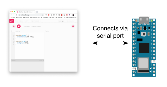
In the Introduction to Asynchronous Serial Communication lab, you learned about various methods for managing the communications between computers via asynchronous serial communication. These included formatting your data as ASCII-encoded strings or raw serial bytes and managing the flow of data using handshaking. In the P5.js WebSerial Input Lab, you sent data from one sensor to a personal computer. In this lab, you’ll send data from multiple sensors to a program in p5.js. using the p5.WebSerial library. You’ll use the data from the sensors to create a pointing-and-selecting device (i.e. a mouse).
What You Should Know
To get the most out of this tutorial, you should know what a microcontroller is and how to program them. You should also understand asynchronous serial communication between microcontrollers and personal computers. You should also understand the basics of P5.js. It would also help to go through the following labs first:
- Lab: Intro to Asynchronous Serial Communication
- Lab: Serial Input to P5.js using p5.WebSerial
- Lab: Serial Output From P5.js using p5.WebSerial
These videos might help in understanding this lab as well:
- Video: Two-way Serial Communication (Call-and-Response)
- These videos are explained in the Processing programming environment, but the concepts still apply:
Things You’ll Need
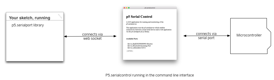
For this lab, you’ll need the hardware below, and you’ll need the same software setup as the WebSerial Input to P5.js lab: You’ll create a p5.js sketch. You’ll also use the p5.WebSerial library. You can use the p5.js web editor or your favorite text editor for this (the Visual Studio Code editor works well).
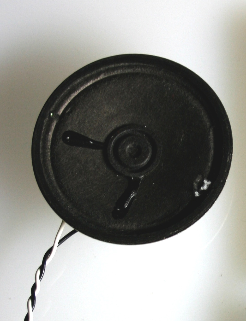
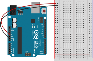
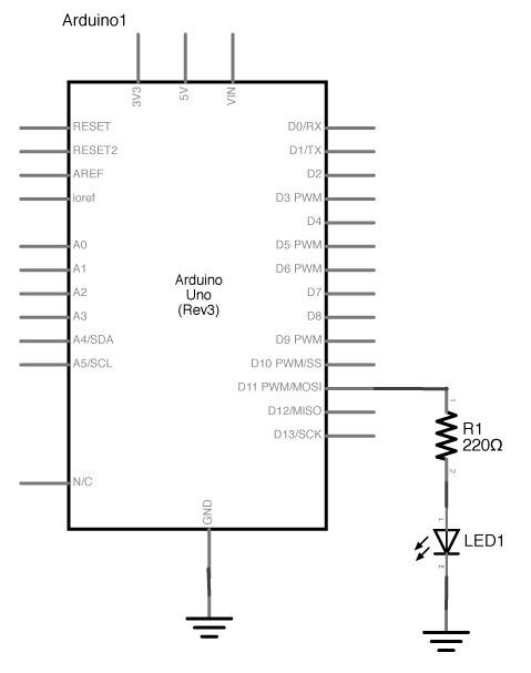
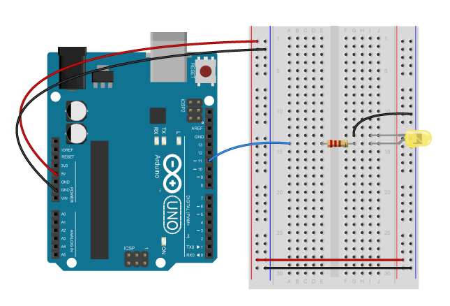
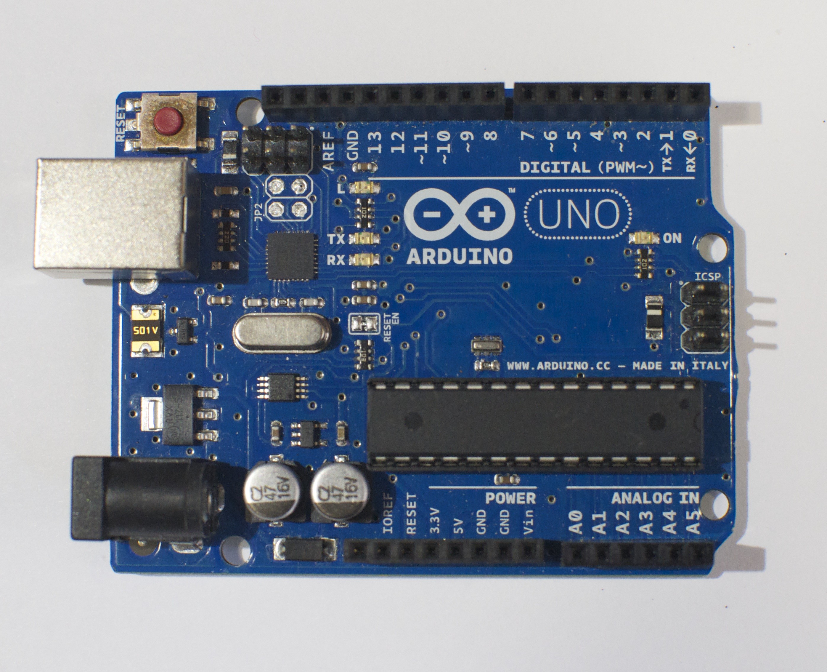
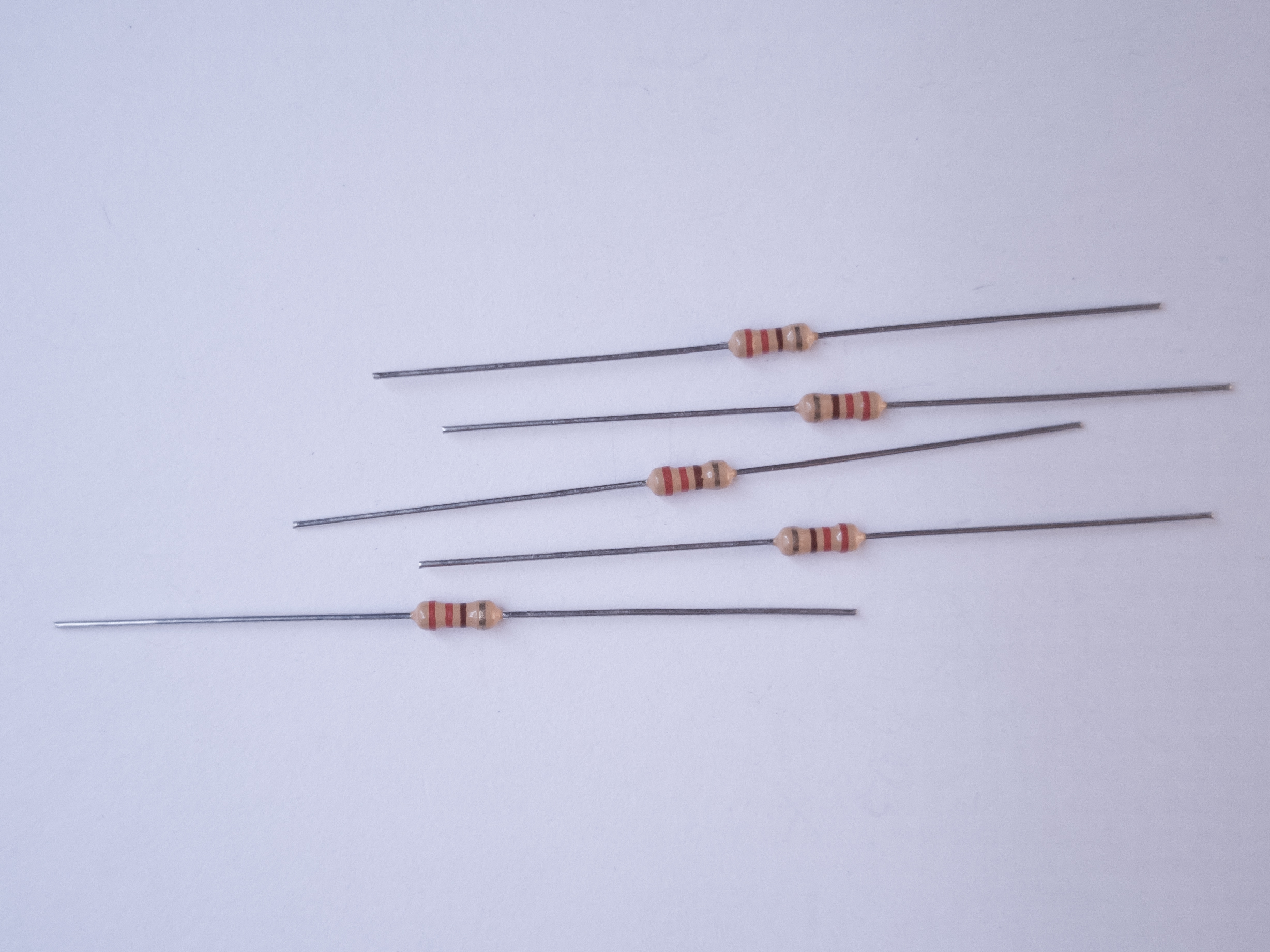
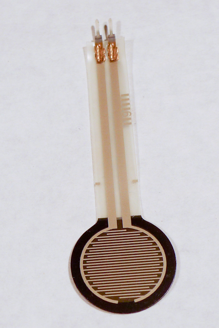
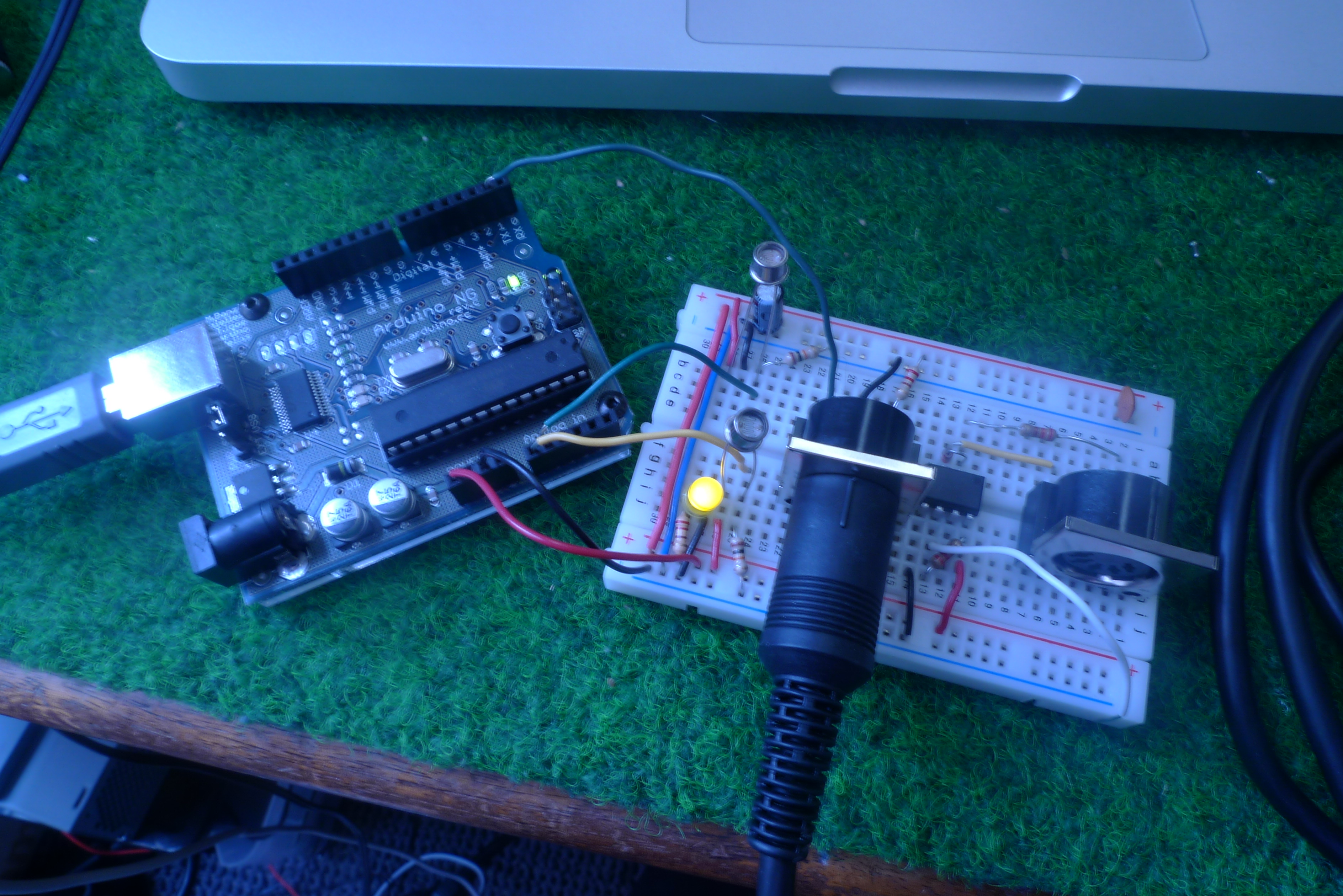
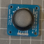
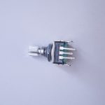
Figures 1-5 below are the parts you’ll need for this exercise. Click on any image for a larger view.


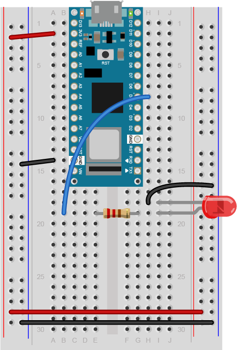
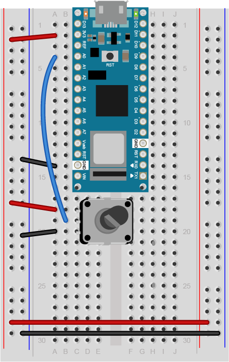
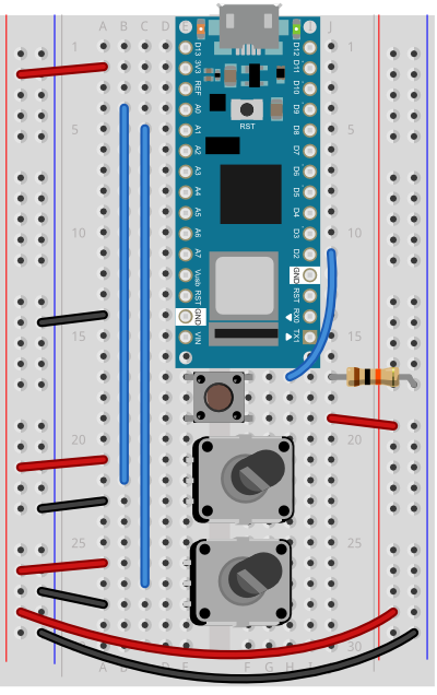
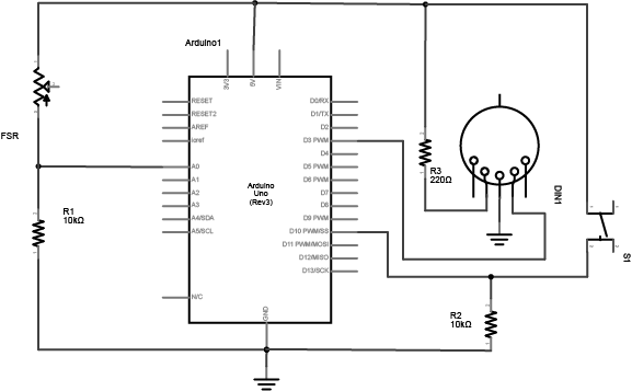
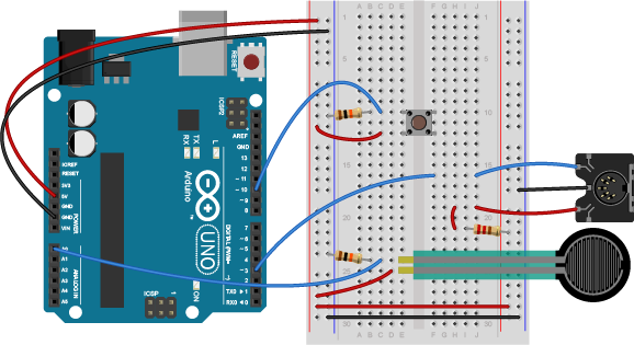
Connect the Sensors
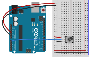
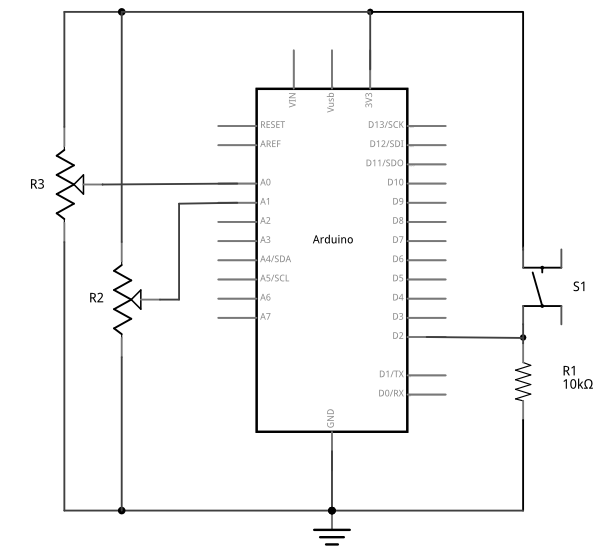
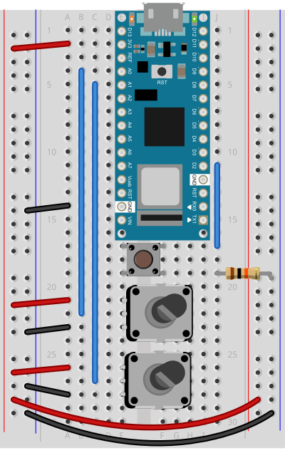
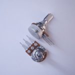
For this exercise, you’re going to need two analog inputs to your microcontroller, and one digital input. It doesn’t matter what they are, so use something that’s easy for you to set up. The photos and schematic in this lab show potentiometers and a pushbutton. You don’t have to use these, though. Any three sensor inputs will do the job. If you’re looking for options, consider:
As long as you have three sensors that will output changing readings, you can follow this lab.
Connect the two analog sensors to analog pins 0 and 1 like you did in the analog input to Arduino lab. Connect a pushbutton to digital pin 2 like you did in the digital input and output with Arduino lab.

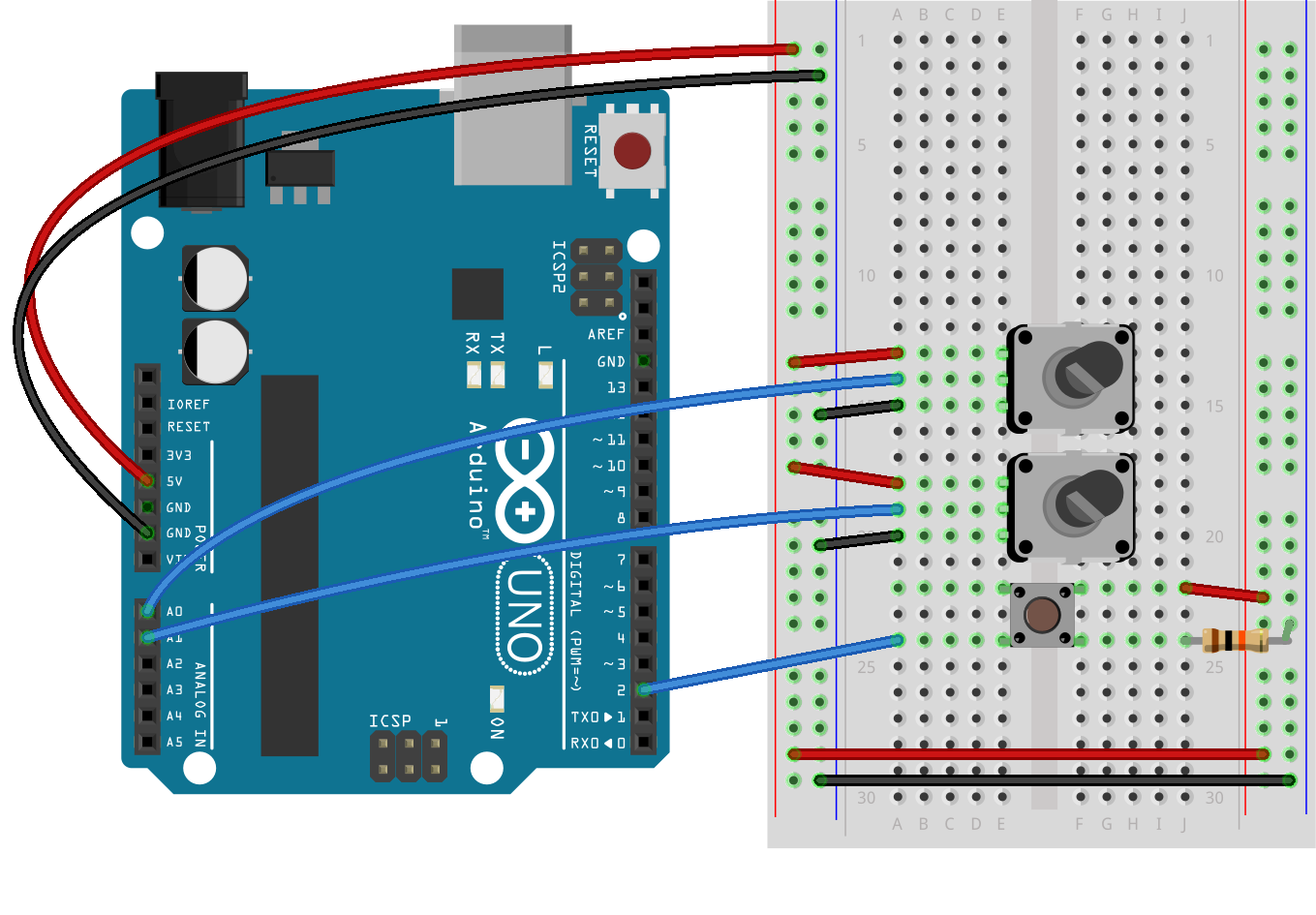
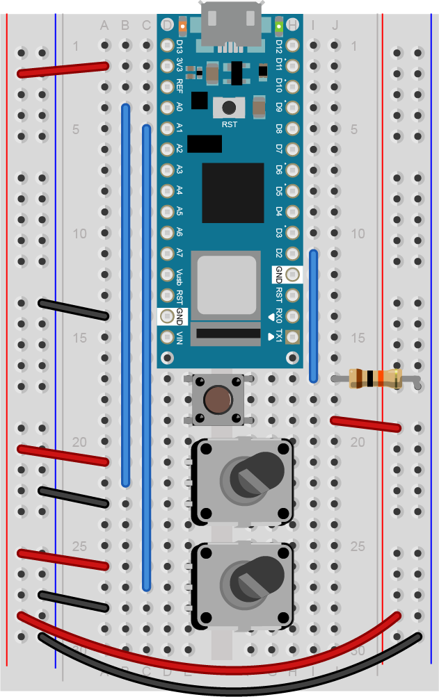
(Diagrams made with Fritzing, a circuit design program)
Sending Multiple Serial Data using Punctuation
You’re going to program the microcontroller to read the pushbutton and two analog sensors just like you did in the Intro to Serial Communications Lab. When you have to send multiple data items, you need a way to separate them. If you’re sending them as ASCII-encoded strings, it’s simple: you can just put non-numeric punctuation bytes between them (like a comma or a space) and a unique termination punctuation at the end (like a newline and/or carriage return).
This program will send the two analog sensor values and then the pushbutton. All three will be ASCII-encoded numeric strings, separated by commas. The whole line of sensor values will be terminated by carriage return (\r, ASCII 13) and newline (\n, ASCII 10).
const int buttonPin = 2;      // digital input

void setup() {
  // configure the serial connection:
  Serial.begin(9600);
  // configure the digital input:
  pinMode(buttonPin, INPUT);
}

void loop() {
  // read the first analog sensor:
  int sensorValue = analogRead(A0);
  // print the results:
  Serial.print(sensorValue);
  Serial.print(",");

  // read the second analog sensor:
  sensorValue = analogRead(A1);
  // print the results:
  Serial.print(sensorValue);
  Serial.print(",");

  // read the button:
  sensorValue = digitalRead(buttonPin);
  // print the results:
  Serial.println(sensorValue);
}
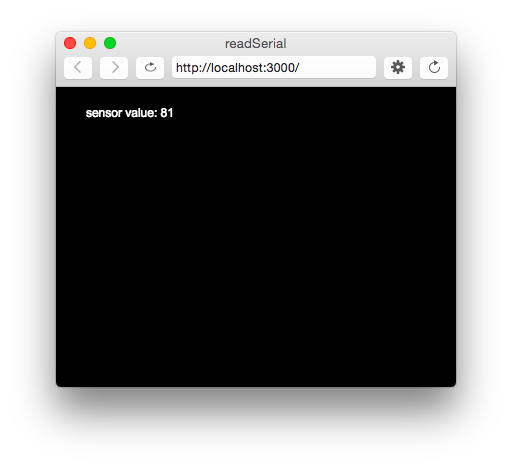
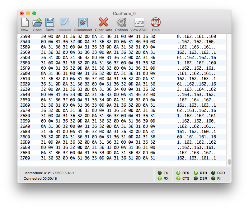
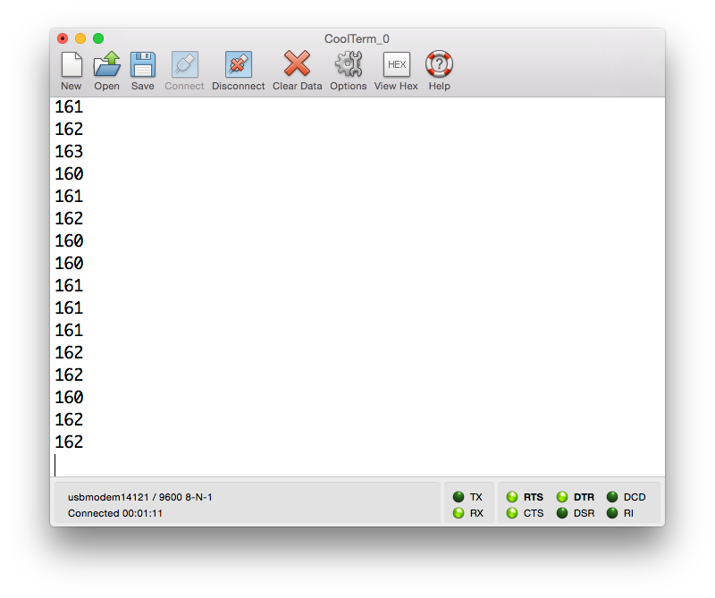
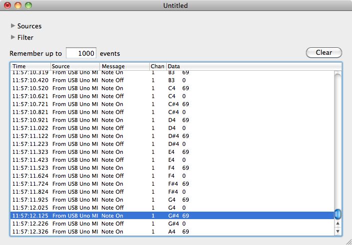
When you run this and output it to the Serial Monitor, you should see something like this:
348,363,1
344,362,1
345,363,1
344,375,0
365,374,0
358,369,0
355,369,0
352,373,0
356,373,0
Turn the potentiometers (or tweak the analog sensors) and push the button. Now you’ve got a data format: three sensors, comma-separated, terminated by carriage return and newline. This means that you already have an algorithm for how you’re going to program p5.js to read the serial input. You’ll see that algorithm in the next section.
Receive the data in P5.js
Now write a P5.js sketch that reads the data as formatted by the Arduino program above. The setup will be the same as it was in the Serial Input to p5.js using WebSerial lab. The checklist from that lab lays out all the important parts you need.
The sketch you’re going to write will:
- Read the incoming serial data into a string until a carriage return and newline appear
- split the string into substrings on the commas
- convert the substrings into numbers
- assign the numbers to variables to change your programNow that you’ve got a plan, put it into action.
Make a P5.js sketch. If you’re using the p5.js web editor, make a new sketch. Click the Sketch Files tab, and then choose the index.html file. Edit the head of the document as you did for the other p5.webserial labs. It should look like this:
<script src="https://cdnjs.cloudflare.com/ajax/libs/p5.js/1.4.0/p5.js"></script>

<script src="https://unpkg.com/p5-webserial@0.1.1/build/p5.webserial.js"></script>
The setup of your sketch will initialize the P5.webserial library and define your callback functions for serial events as you did in other sketches. It should look like this:
// variable to hold an instance of the p5.webserial library:
const serial = new p5.WebSerial();

// HTML button object:
let portButton;
let inData;                      // for incoming serial data
let outData;                     // for outgoing data

function setup() {
  createCanvas(400, 300);          // make the canvas
  // check to see if serial is available:
  if (!navigator.serial) {
    alert("WebSerial is not supported in this browser. Try Chrome or MS Edge.");
  }
  // if serial is available, add connect/disconnect listeners:
  navigator.serial.addEventListener("connect", portConnect);
  navigator.serial.addEventListener("disconnect", portDisconnect);
  // check for any ports that are available:
  serial.getPorts();
  // if there's no port chosen, choose one:
  serial.on("noport", makePortButton);
  // open whatever port is available:
  serial.on("portavailable", openPort);
  // handle serial errors:
  serial.on("requesterror", portError);
  // handle any incoming serial data:
  serial.on("data", serialEvent);
  serial.on("close", makePortButton);
}
function draw() {

}

// if there's no port selected,
// make a port select button appear:
function makePortButton() {
  // create and position a port chooser button:
  portButton = createButton('choose port');
  portButton.position(10, 10);
  // give the port button a mousepressed handler:
  portButton.mousePressed(choosePort);
}

// make the port selector window appear:
function choosePort() {
  serial.requestPort();
}

// open the selected port, and make the port
// button invisible:
function openPort() {
  // wait for the serial.open promise to return,
  // then call the initiateSerial function
  serial.open().then(initiateSerial);

  // once the port opens, let the user know:
  function initiateSerial() {
    console.log("port open");
  }
  // hide the port button once a port is chosen:
  if (portButton) portButton.hide();
}

// read any incoming data as a byte:
function serialEvent() {

}

// pop up an alert if there's a port error:
function portError(err) {
  alert("Serial port error: " + err);
}

// try to connect if a new serial port
// gets added (i.e. plugged in via USB):
function portConnect() {
  console.log("port connected");
  serial.getPorts();
}

// if a port is disconnected:
function portDisconnect() {
  serial.close();
  console.log("port disconnected");
}
Change the serialEvent() function to read the incoming serial data as a string until it encounters a carriage return and newline (“\r\n”). Then check to see that the resulting string has a length greater than 0 bytes. If it does, use the split() function to split it in to an array of strings. If the resulting array is at least three elements long, you have your three sensor readings. The first reading is the first analog sensor, and can be mapped to the horizontal movement using the locH variable. The second is the second analog sensor and can be mapped to the locV variable. The third is the button. When it’s 0, set the circleColor variable equal to 255 and when it’s 1, set the variable to 0. Here’s how:
function serialEvent() {
  // read a string from the serial port
  // until you get carriage return and newline:
  var inString = serial.readStringUntil("\r\n");
  //check to see that there's actually a string there:
  if (inString) {
    // split the string on the commas:
    var sensors = split(inString, ",");
    if (sensors.length > 2) {
      // if there are three elements
      // element 0 is the locH:
      locH = map(sensors[0], 0, 1023, 0, width);
      // element 1 is the locV:
      locV = map(sensors[1], 0, 1023, 0, height);
      // element 2 is the button:
      circleColor = 255 - sensors[2] * 255;
    }
  }
}
Note the mappings of sensors[0] and sensors[1]. If you’re not using potentiometers as the first two inputs on your Arduino, then you should use the input mappings for your sensors instead of 0 and 1023. If your analog values are greater than the width of the sketch or the height, the circle will be offscreen, which is why you have to map your sensor range to the screen size.
Program the draw() function to draw a circle that’s dependent on three global variables, locH, locV, and circleColor. Add these three globals to the top of the program:
// variables for the circle to be drawn:
let locH, locV;
let circleColor = 255;
Finally, here is the draw function:
function draw() {
  background(0);               // black background
  fill(circleColor);           // fill depends on the button
  ellipse(locH, locV, 50, 50); // draw the circle
}
If you run this, you should see the circle moving onscreen whenever you change your sensors. When you press the pushbutton, the circle will disappear. Okay, it’s not exactly a mouse, but you are controlling an animation from a device that you built.
Flow Control: Call and Response (Handshaking)
You’ve seen now that by coming up with a serial format (called a protocol), you can write the algorithm for receiving it even before you see any data. You can send multiple pieces of data this way, as long as you format it consistently.
Sometimes you can run into a problem when the sender sends faster than the receiver can read. When this happens, the receiver program slows down as the serial buffer fills up. You can manage this by implementing some form of flow control. The simplest way do to this is using a call-and-response method, where the sending program only sends when it’s told to do so, and the receiving program has to request new data every time it finishes reading what it’s got.
You can add handshaking to the code above fairly simply. Modify the Arduino code as follows. First, add a a new block of code in the setup() This block sends out a message until it gets a byte of data from the remote computer:
void setup() {
  Serial.begin(9600);
  while (Serial.available() <= 0) {
    Serial.println("hello"); // send a starting message
    delay(300);              // wait 1/3 second
  }
}
Now, modify the loop() by adding an if() statement to look for incoming serial data and read it.
void loop() {
  if (Serial.available() > 0) {
    // read the incoming byte:
    int inByte = Serial.read();
    // read the sensor:
    int sensorValue = analogRead(A0);
    // print the results:
    Serial.print(sensorValue);
    Serial.print(",");

    // read the sensor:
    sensorValue = analogRead(A1);
    // print the results:
    Serial.print(sensorValue);
    Serial.print(",");

    // read the sensor:
    sensorValue = digitalRead(buttonPin);
    // print the results:
    Serial.println(sensorValue);
  }
}
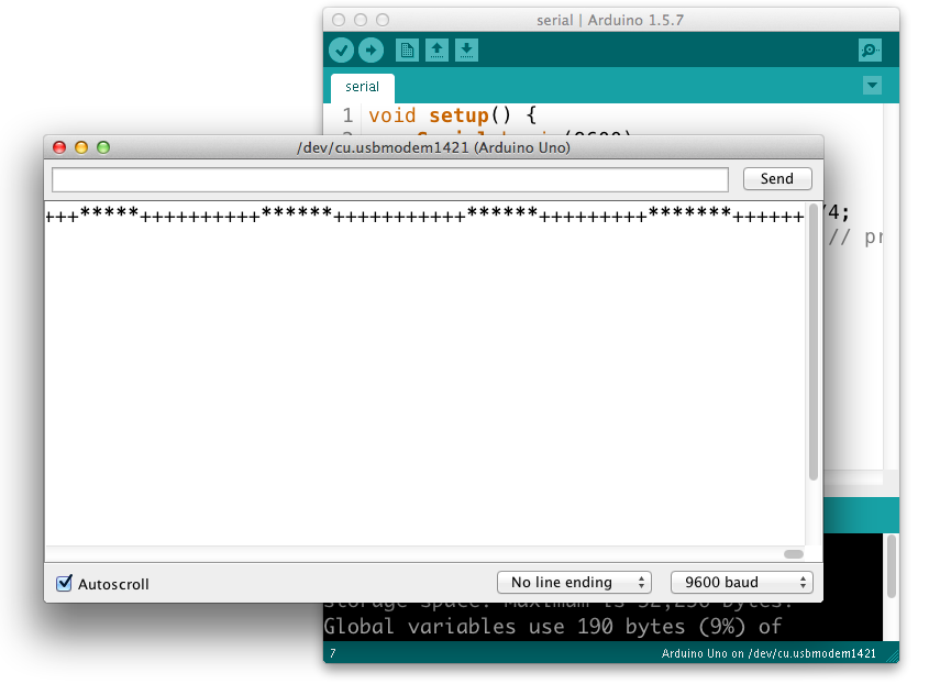
The rest of the sketch remains the same. When you run this and open the serial monitor, you’ll see:
hello
hello
hello
hello
Type any character in the output box and click Send. You’ll get a string of sensor values at the end of your hellos:
510,497,0
Type another character and click Send. It doesn’t matter what character you send, but the loop will always wait for an incoming byte before sending a new set of sensor values. When you write a program to receive this format, it just has to behave the same way you did:
- Open the serial port
- Wait for a hello
- Send a byte to request data
- Begin loop:
- Wait for one set of data
- Send a byte to request new data
- end loop
Next, modify the P5.js sketch. Most of the changes are in the serialEvent() function. The initial “hello” messages will trigger this function, so when you get a “hello” or any other string, you need to send a byte back so that the Arduino has a byte available to read. Here’s the new serialEvent():
function serialEvent() {
  // read a string from the serial port
  // until you get carriage return and newline:
  var inString = serial.readStringUntil("\r\n");
  //check to see that there's actually a string there:
  if (inString) {
    if (inString !== "hello") {
      // if you get hello, ignore it
      // split the string on the commas:
      var sensors = split(inString, ",");
      if (sensors.length > 2) {
        // if there are three elements
        // element 0 is the locH:
        locH = map(sensors[0], 0, 1023, 0, width);
        // element 1 is the locV:
        locV = map(sensors[1], 0, 1023, 0, height);
        // element 2 is the button:
        circleColor = 255 - sensors[2] * 255;
        // send a byte back to prompt for more data:
        serial.print('x');
      }
    }
  }
}
You also need to add a line to the initiateSerial() function (which is inside the openPort() function) like so:
 function initiateSerial() {
    console.log("port open");
    // send a byte to start the microcontroller sending:
    serial.print("x");
  }
The reason for this is that if your Arduino is still in the setup() waiting for a byte to arrive, then it needs p5.js to send something when the port is opened. If the Arduino has already broken out of the loop (let’s say you opened the Serial monitor to check), then it is waiting for a byte from p5.js to send the next block of code. Whether it’s in the initiateSerial() function or at the end of the serialEvent() function, by sending a byte when you know the port has just been opened in p5.js, you force the Arduino to send you new data.
That’s it. Your sketch should still run just as it did before, though the serial communication is managed better now, because Arduino’s only sending when P5.js is ready to receive.
You can see the sketch running on GitHub at this link. You can see the source files for copying into the p5.js editor at this link.
Advantages of Raw Binary vs. ASCII
All the examples shown here sent the sensor values as ASCII-encoded strings. As mentioned above, that means you sent three bytes to send a three-digit value. If that same value was less than 255, you could send it in one raw binary byte. So ASCII is definitely less efficient. However, it’s more readable for debugging purposes, and if the receiving program is well-suited to convert strings to numbers, then ASCII is a good way to go. If the receiver’s not so good at converting strings to numbers (for example, it’s more challenging to read a multiple byte string in Arduino than in Processing) then you may want to send your data as binary values.
Advantages of Punctuation or Call-and-Response
The punctuation method for sending multiple serial values may seem simpler, but it has its limitations. You can’t easily use it to send binary values, because you need to have a byte with a unique value for the punctuation. In the example above, you’re using the value 10 (ASCII newline) as punctuation, so if you were sending your sensor values as raw bytes, you’d be in trouble when the sensor’s value is 10. The receiver would interpret the 10 as punctuation, not as a sensor value. In contrast, call-and-response can be used whether you’re sending data as raw binary values or as ASCII-encoded values.
Sometimes the receiver reads serial data slower than the sender sends it. For example, if you have a program that does a lot of graphic work, it may only read serial data every few milliseconds. The serial buffer will get full in that case, you’ll notice a lag in response time. This is when it’s good to switch to a call-and-response method.
Build an Application of Your Own
You just duplicated the basic functionality of a mouse; that is, a device with two analog sensors that affect X and Y, and a digital sensor (mouse button). What applications can you think of that could use a better physical interface for a mouse? A video editor that scrubs forward and back when you tilt a wand? An action game that reacts to how hard you hit a punching bag? An instructional presentation that speeds up if you shift in your chair too much? A music program driven by a custom musical instrument that you design?
Create a prototype in Arduino and P5.js, Node.js, Processing, or whatever programming environment you choose. Come up with a physical interface that makes it clear what actions map to what movements and actions. Figure out which actions can and should be possible at the same time. Present a working software and hardware model of your idea.