Lab: Arduino to Digital Audio Workstation

This lab covers the process of taking MIDI messages sent from the Arduino and creating sound with them via a Digital Audio Workstation (DAW) such as Ableton LIVE, Logic or Garageband.

Introduction

This lab covers the process of taking MIDI messages sent from the Arduino and creating sound with them via a Digital Audio Workstation (DAW) such as Ableton LIVE, Logic or Garageband.

What You’ll Need to Know

To get the most out of this lab, you should be familiar with the following concepts. You can check how to do so in the links below:

Things You’ll Need

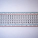
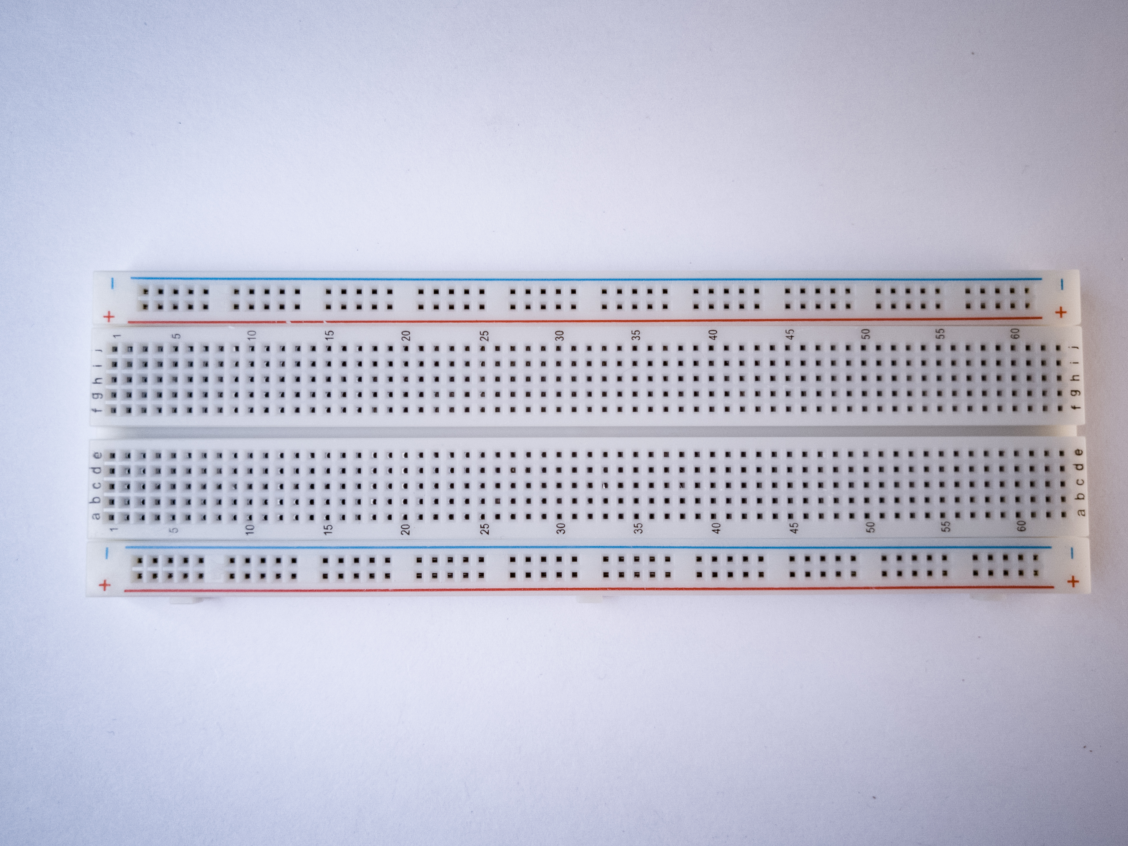
Photo of a solderless breadboard
Figure 1. A solderless breadboard.
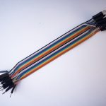
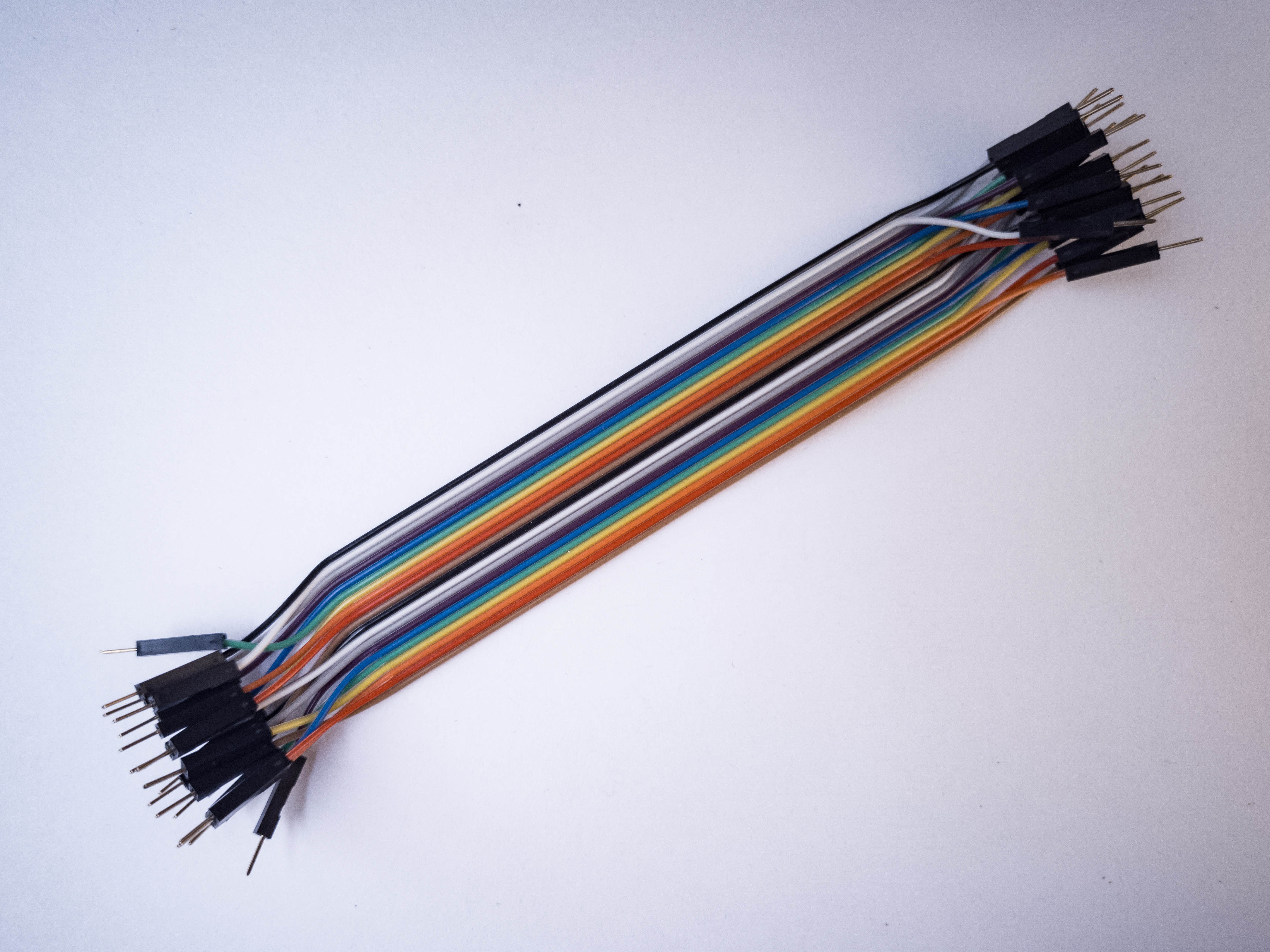
Photo of flexible jumper wires
Figure 2. 22 AWG hookup wire
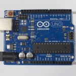
An Arduino Uno. The USB connector is facing to the left, so that the digital pins are on the top of the image, and the analog pins are on the bottom.
Figure 3. An Arduino Uno or…
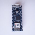
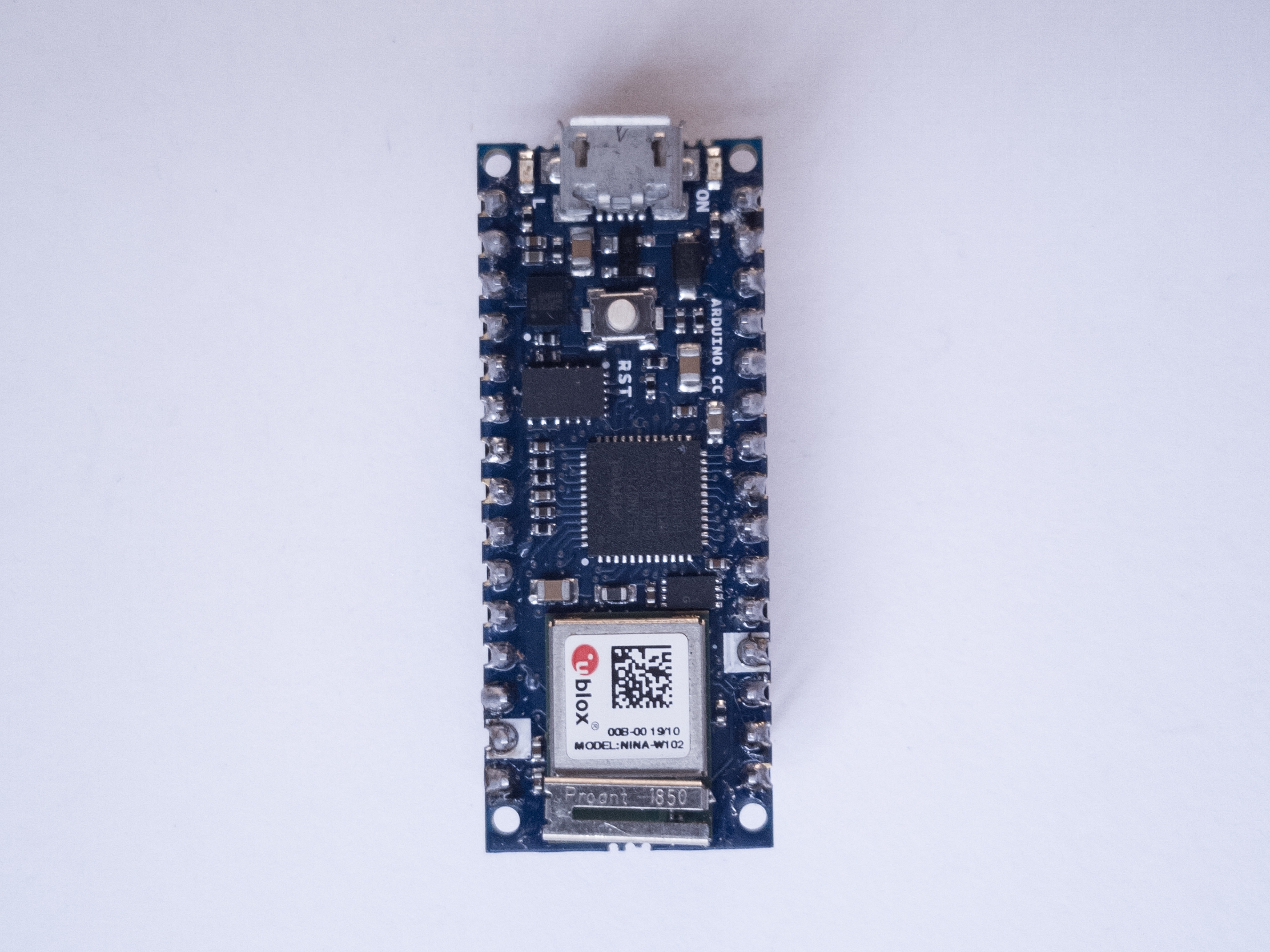
Photo of an Arduino Nano 33 IoT module. The USB connector is at the top of the image, and the physical pins are numbered in a U-shape from top left to bottom left, then from bottom right to top right.
Figure 4. Arduino Nano 33 IoT
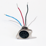
Photo of a 5-pin MIDI socket. Three wires protrude from the back.
Figure 5. A 5-pin MIDI socket (for the Uno version only)
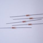
Photo of a handful of 220-ohm resistors.
Figure 6. 220-ohm resistors (for the Uno version only)
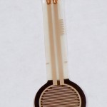
Force-sensing resistor (FSR). These sensors have a resistive rubber inside that changes its resistance depending on the force with which you press on the sensor. The one shown is a flat disc about 5cm in diameter
Figure 7. Force-sensing resistor
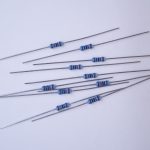
Photo of a handful of 10-kilohm resistors
Figure 8. 10-kilohm resistors.
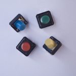
Photo of four breadboard-mounted pushbuttons
Figure 9. Pushbuttons
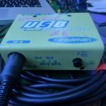
Photo of a MIDISport USB-to-MIDI adaptor.
Figure 10. MIDISport 2×2 or other USB-to-MIDI interface (Serial versions only). ITP has some in the equipment room.

MIDI approaches: Serial, SoftwareSerial, or MIDIUSB

There are three approaches you can take to MIDI output, depending on the board you’re using and the application you have in mind.

If you’re communicating with a MIDI sound module like a synthesizer or sample, you’ll need to use either Serial or SoftwareSerial output. On the Uno, SoftwareSerial is best. On most other Arduino models, there is a second hardware serial port, Serial1, that you can use for MIDI output.

If you’re communicating with a MIDI program like Ableton, GarageBand, or a soundFont synth like Sforzando, either on a laptop or mobile device, then MIDIUSB is the way to go. The Uno can’t communicate using MIDIUSB, but the Nano 33 IoT, the MKR series, the Leonardo, Micro, or Due can.

SoftwareSerial Approach

If you’re using an Uno or any board with only one serial port, the SoftwareSerial library is your best bet. This section describes how to wire and program your board for SoftwareSerial.

Build the MIDI Circuit

Use the MIDi circuit from the MIDI Output lab, or any variation on it you want, as long as it sends MIDI:

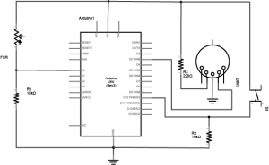
 Schematic view of an Arduino connected to a voltage divider and a switch. The switch and voltage divider are connected as shown above. the MIDI connector's pin 2 is connected to a 220-ohm resistor, and the other side of the resistor is connected to +5 volts. Pin 3 of the MIDI connector is connected to ground. Pin 4 of the MIDI connector is connected to the Arduino's digital pin 3.
Figure 11. Schematic view of an Arduino connected to a voltage divider and a switch, with a MIDI connector as well.
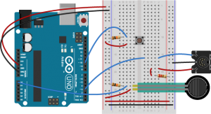
Breadboard view of an Arduino connected to a voltage divider, a switch, and a MIDI connector. This view builds on the breadboard view above. The voltage divider and the switch are connected to analog pin 0 and digital pin 10 as described above. The MIDI connector's pin 2 is connected row 19 in the right center section of the breadboard. A red wire connects it to row 21. From there, a 220-ohm resistor connects to the right side voltage bus. The MIDI connector's pin 3 connects to the right side ground bus. The connector's pin 4 connects to row 14 in the right center section, and a blue wire connects from there to digital pin 3 on the Arduino.
Figure 12. Breadboard view of an Arduino connected to a voltage divider, a switch, and a MIDI connector.

This circuit doesn’t actually match the MIDI specification, but it works with all the MIDI devices we’ve tried it with. This circuit includes an analog and a digital sensor to allow for physical interactivity, but those aren’t necessary to send MIDI data.

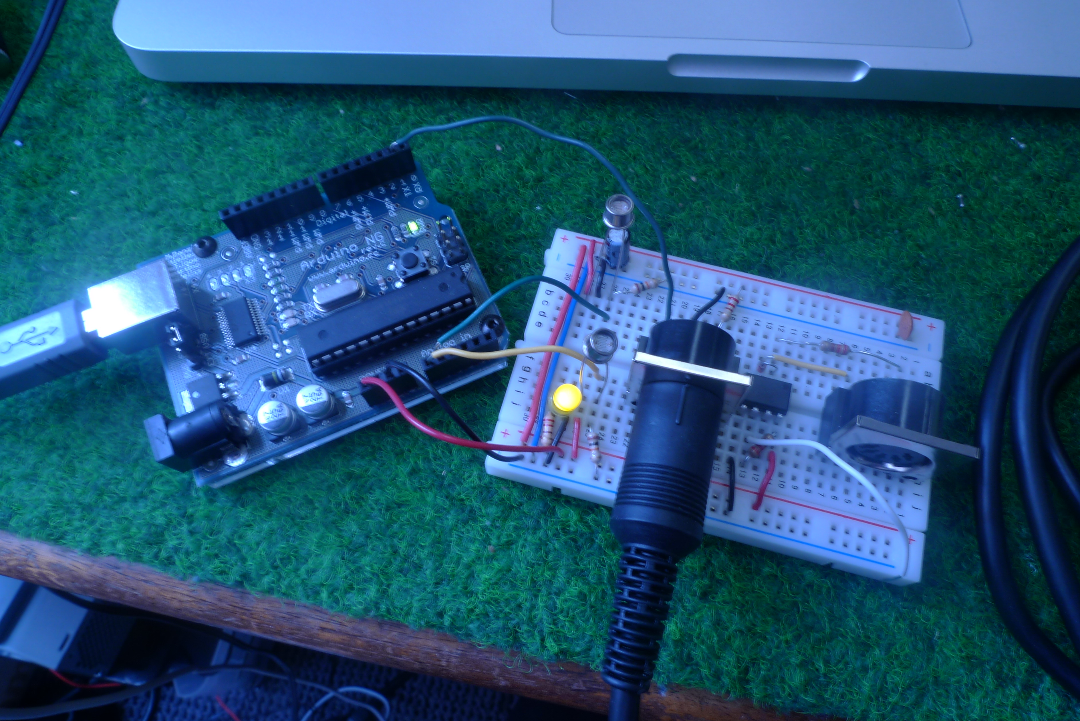
Here we have a little Arduino instrument we whipped up using the MIDI Output Lab. It features two photocells, one controlling the pitch (or note being sent) and the other controlling the volume. Now that we are sending MIDI messages, we need to get them into the computer.
USB-to-MIDI Interfaces

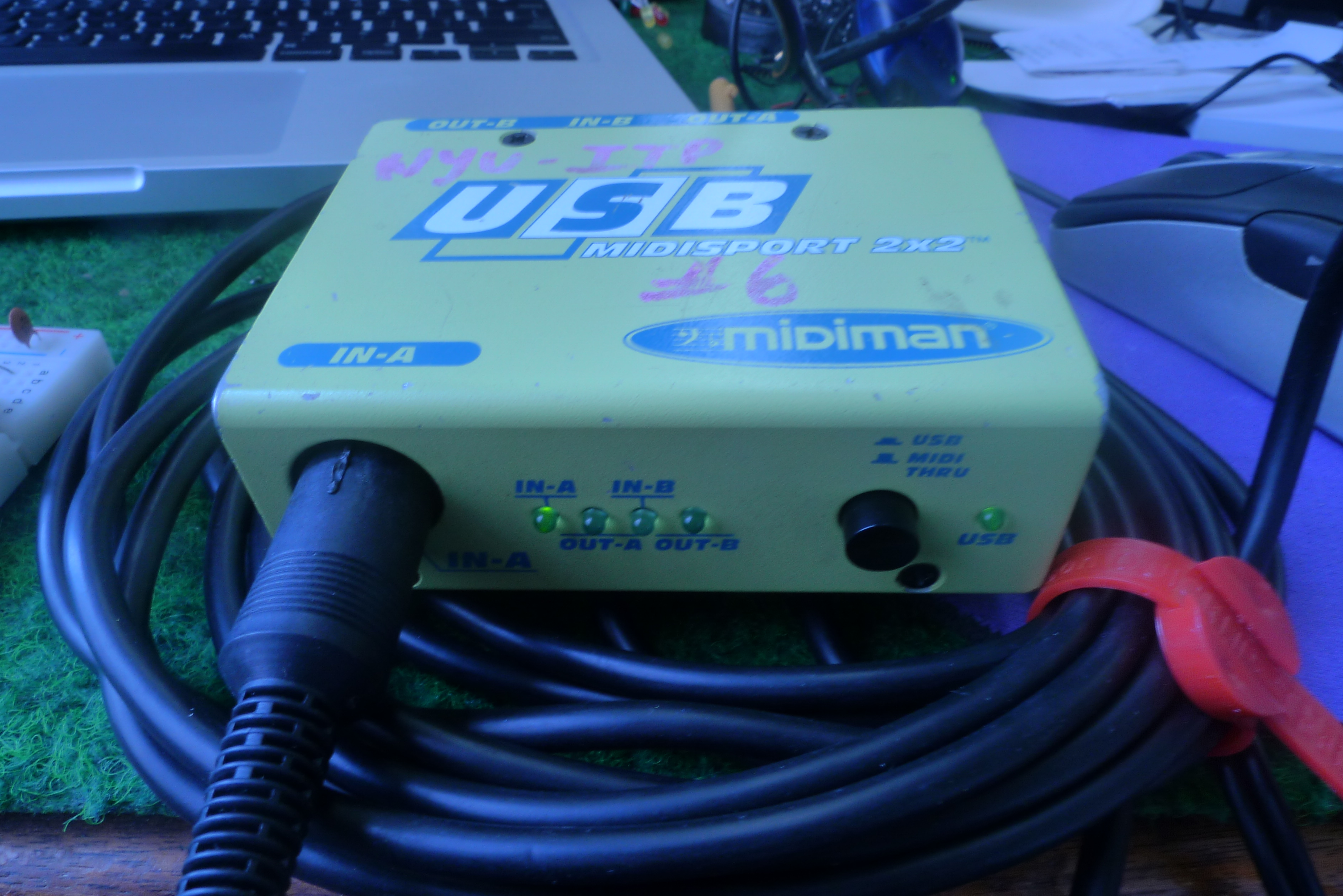
To get the MIDI messages into the computer, you will need a USB MIDI interface. A MIDISport 2×2 like the one pictured can be found in the Equipment Room. For more information see the technical details on the MIDISport. The interface connects to your computer via the USB cable and to the Arduino via a MIDI cable. Connect the Arduino to the MIDI In port of the interface.

Alternatively, you can use the MIDIUSB library to send MIDI via USB if you are using an ARM-based Arduino board like the MKR series. Doing so will eliminate the need for a USB-to-MIDI adapter like the MIDISport. Your Arduino will communicate directly with the computer as a MIDI device over USB.

Note on MIDIUSB and Serial Ports

The MIDIUSB library on the SAMD boards (MKRZero, MKR1xxx, Nano 33IoT) has an unusual behavior: using it changes the serial port enumeration. When you include the MIDIUSB library in a sketch, your board’s serial port number will change. For example, on MacOS, if the port number is /dev/cu.usbmodem14101, then adding the MIDIUSB library will change it to /dev/cu.usbmodem14102. Removing the MIDIUSB library will change it back to /dev/cu.usbmodem14101. Similarly, if you double-tap the reset button to put the board in bootloader mode, the serial port will re-enumerate to its original number.

Windows and MIDIUSB

You may have trouble getting these MIDI sketches to work on Windows. On Windows, the default Arduino drivers must be uninstalled so the system can recognize the Arduino as both serial device and MIDI device. Read this issue and follow the instructions there.

Audio MIDI Setup

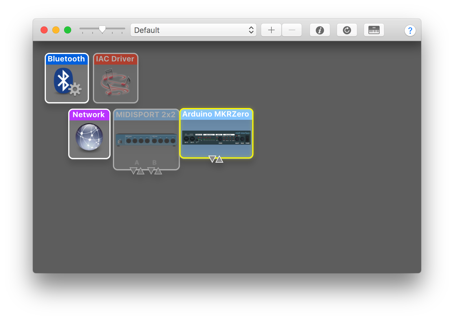
To connect with your device on MacOS you’ll need the Audio MIDI Setup application. It’s in the Utilities directory of your Applications directory.

A screenshot of the Audio MIDI setup window in MacOS. The window shows the MIDi devices that the operating system recognizes.
Figure 15. The Audio MIDI setup window in MacOS

If you’re not using the MIDIUSB library, you will need to download drivers for the MIDI interface you are using. Go to the manufacturer’s website (for example, M-Audio’s driver page, where you can find the MIDISport under MIDI Interfaces) and download the drivers that correspond to your interface and operating system. Once the drivers are installed, the interface should be recognized by your computer. To check this, open up Audio MIDI Setup. If you only see the Audio setup, click Window in your task bar and select Show MIDI Studio. You should then see the window pictured here and the interface should appear colored in. Interfaces that are not connected will appear faded as shown above.

Preferences in your DAW Software

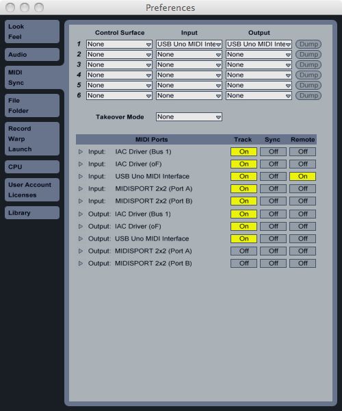
Now that your computer recognizes the MIDI interface, you need to set up your preferences in the DAW. In this case, we are using Ableton Live so open up the preferences window. Ableton will recognize the interface but the ports need to be set. Find your interface and where it says Input, turn on the button listed under Track. Now Live will receive MIDI messages on these ports.

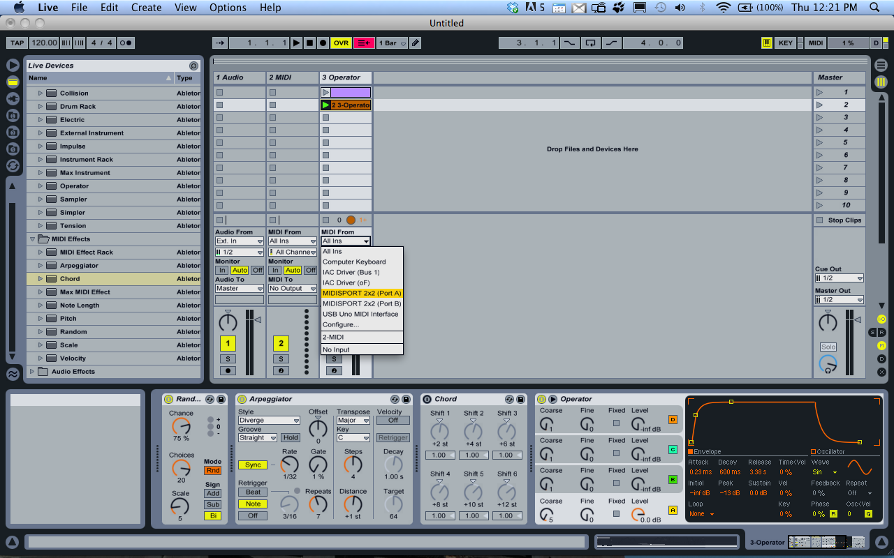
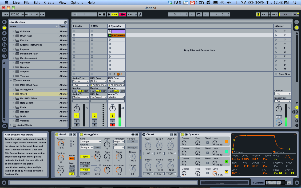
Select a MIDI track and add an instrument. Live has some instruments built in or you can use a third party plugin as a sound generator. In the screenshot above, the Operator FM synthesizer is selected. If you only have one device going in to Live, it is fine to leave the track’s MIDI input set to “All Ins.” If you have more than one, you will probably want to select a specific port as shown in the image above.

The last step is to Arm the track by clicking the Arm button on the bottom of the channel strip. Now you are ready to go. Start sending MIDI from the Arduino and you should be hearing your lovely new instrument.

MIDI Monitor App

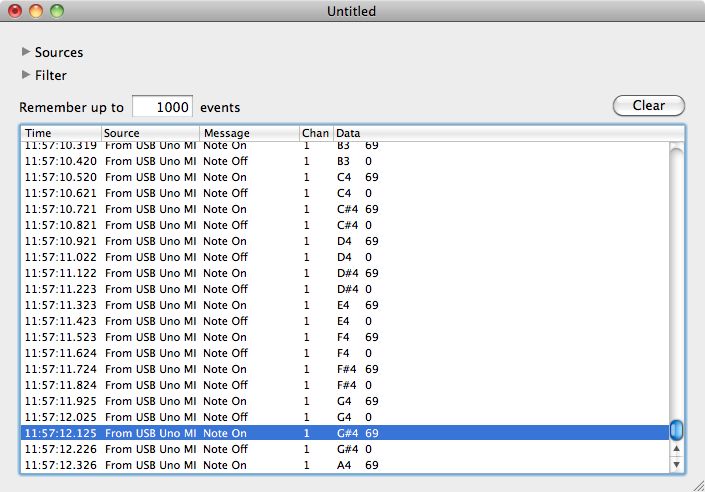
The Snoize MIDI monitor is a useful application to have if you do lots of MIDI input to your computer. You can download it from Snoize’s download page.

When running the application, MIDI Monitor will show you all the information that is coming in through the MIDI interface, such as the source, channel, message and note values. This is especially useful for debugging your MIDI instrument.

Lab: Mouse Control With Joystick

In this lab, you’ll build an alternative computer mouse using an Arduino Leonardo using a joystick to move the mouse left, right, up and down. You’ll use the joystick’s select button to replace the mouse button as well.

Introduction

In this lab, you’ll build an alternative computer mouse using an Arduino Leonardo using a joystick to move the mouse left, right, up and down. You’ll use the joystick’s select button to replace the mouse button as well. You’ll see how to scale the analog outputs of the joystick to a reasonable range using the map() function.

A joystick is typically made up of two potentiometers, one for the X axis and one for the Y axis. The potentiometers are mounted so that when the joystick is at rest in the center, the potentiometers are at the middle of their range. Some joysticks like the Thumb Joystick used here also have a pushbutton that you can press by pushing down on the stick. (Note: SparkFun and Parallax have equivalent models as well.)

What You’ll Need to Know

To get the most out of this lab, you should be familiar with the following concepts. You can check how to do so in the links below:

Things You’ll Need

Figures 1-6 show the parts you’ll need for this exercise. Click on any image for a larger view.

A short solderless breadboard with two rows of holes along each side. There are no components mounted on the board.
Figure 1. A solderless breadboard.
Photo of an Arduino Nano 33 IoT module. The USB connector is at the top of the image, and the physical pins are numbered in a U-shape from top left to bottom left, then from bottom right to top right.
Figure 2. Arduino Nano 33 IoT
Three 22AWG solid core hookup wires. Each is about 6cm long. The top one is black; the middle one is red; the bottom one is blue. All three have stripped ends, approximately 4 to 5mm on each end.
Figure 3. 22AWG solid core hookup wires.
Resistors. Shown here are 220-ohm resistors. You can tell this because they have two red and one brown band, followed by a gold band.
Figure 4. Resistors. Shown here are 220-ohm resistors.  For this exercise, you’ll need 10-kilohm resistors (10K resistors are brown-black-orange. For more, see this resistor color calculator)
A pushbutton with two wires soldered one to each of the button's contacts.
Figure 5. A pushbutton with two wires soldered one to each of the button’s contacts. Any switch will do the job as well.
Photo of a breadboard-mountable joystick, This component is mounted on a printed circuit board that's about 4cm on each side. The joystick itself is about 6cm tall, controllable by a thumb. There are five pins on one side of the PCB for mounting on the breadboard.
Figure 6. A breadboard-mountable joystick

Click on any image for a larger view

About mouse control

NOTE: The sketches contained in this lab will cause the Arduino Leonardo to take control of your mouse. Make sure they’re working properly before you add the mouse commands. The example doesn’t introduce the mouse commands until the end of the lab. Instead, messages are printed to the serial monitor to tell you what should happen. When you’ve run this and seen the serial messages occurring when you think they should, then you can add the mouse commands safely.

The sketches here will work on an Uno until you add the mouse commands. So you can test this on an Uno simply by commenting out any line that says Mouse.begin() or Mouse.move().

Note on Mouse, Keyboard, and Serial Ports

The Mouse and Keyboard libraries on the SAMD boards (MKRZero, MKR1xxx, Nano 33IoT) have an unusual behavior: using them changes the serial port enumeration. When you include the Keyboard library in a sketch, your board’s serial port number will change. For example, on MacOS, if the port number is /dev/cu.usbmodem14101, then adding the Keyboard library will change it to /dev/cu.usbmodem14102. Removing the Keyboard library will change it back to /dev/cu.usbmodem14101. Similarly, if you double-tap the reset button to put the board in bootloader mode, the serial port will re-enumerate to its original number.

Windows and HID Devices

You may have trouble getting these sketches to work on Windows. On Windows, the default Arduino drivers must be uninstalled so the system can recognize the Arduino as both serial device and HID device. Read this issue and follow the instructions there.

Recovering From a Runaway HID (Mouse or Keyboard) Sketch

Programs which control your keyboard and mouse can make development difficult or impossible if you make a mistake in your code. If you create a mouse or keyboard example that doesn’t do what you want it to, and you need to reprogram your microcontroller to stop the program, do this:

Open a new blank sketch.

This sketch is your recovery:

1
2
3
4
5
6
void setup() {
 
}
void loop() {
 
}

Programming the board with this blank sketch removes your mistaken sketch and gives you control again. To do this, however, you need the current sketch to stop running. So:

Put the microcontroller in bootloader mode and upload the blank sketch

On the SAMD boards, you can do this by double-tapping the reset button. The on-board LED will begin glowing, and the bootloader will start so that you get a serial port enumeration, but the sketch won’t run. On the Leonardo and other 32U4-based boards, hold the reset down until you’ve given the upload command. The 32U4 bootloader will take a few seconds before it starts the sketch, so the uploader can take command and load your blank sketch.

Once you’ve got the blank sketch on the board, review the logic of your mistaken Keyboard or Mouse sketch and find the problem before uploading again.

Prepare the breadboard

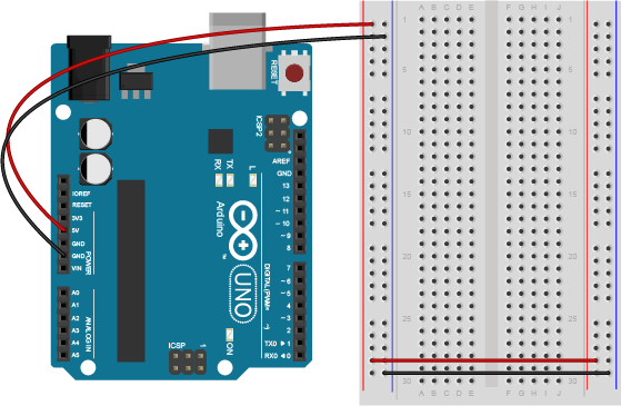
Connect power and ground on the breadboard to power and ground from the microcontroller. On the Arduino module, use the 5V and any of the ground connections as shown below in Figure 7:

An Arduino Leonardo on the left connected to a solderless breadboard, right. The Leonardo's 5V output hole is connected to the red column of holes on the far left side of the breadboard. The Leonardo's ground hole is connected to the blue column on the left of the board. The red and blue columns on the left of the breadboard are connected to the red and blue columns on the right side of the breadboard with red and black wires, respectively. These columns on the side of a breadboard are commonly called the buses. The red line is the voltage bus, and the black or blue line is the ground bus.
Figure 7. An Arduino Leonardo on the left connected to a solderless breadboard, right.
Arduino Nano on a breadboard.
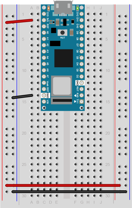
Figure 8. Breadboard view of Arduino Nano mounted on a breadboard.

Figure 8. Breadboard view of an Arduino Nano connected to a breadboard. The +3.3 volts and ground pins of the Arduino are connected by red and black wires, respectively, to the left side rows of the breadboard. +3.3 volts is connected to the left outer side row (the voltage bus) and ground is connected to the left inner side row (the ground bus). The side rows on the left are connected to the side rows on the right using red and black wires, respectively, creating a voltage bus and a ground bus on both sides of the board.

Made with Fritzing


Add a pushbutton

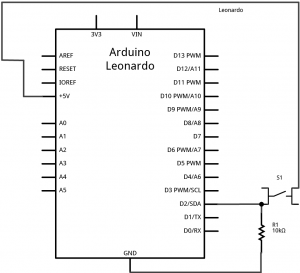
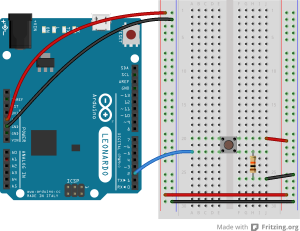
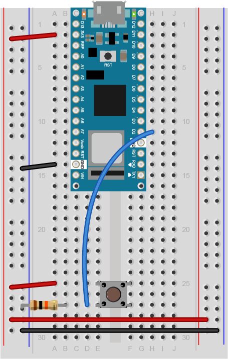
Attach a pushbutton to digital pin 2 as shown below in Figure 10. For Arduino Nano view, see Figure 11. For the schematic view, see Figure 9. Connect one side of the pushbutton to 5 volts, and the other side of the pushbutton to a 10-kilohm resistor. Connect the other end of the resistor to ground. Connect the junction where the pushbutton and the resistor meet to digital pin 2. (For more on this digital input circuit, see the Digital Input Lab).

Schematic drawing of an Arduino Leonardo connected to a pushbutton and two voltage divider inputs. The pushbutton is connected as described in the schematic above. On the left side of the board, two photoresistors are connected to +5 volts. The other sides of the photoresistors are connected to analog inputs A0 and A1, respectively. Two 10-kilohm resistors are also connected to those pins. The other sides of the fixed resistors are connected to ground.
Figure 9. Schematic view of an Arduino Leonardo connected to a pushbutton.
Breadboard drawing of an Arduino Leonardo connected to a pushbutton. The pushbutton straddles the center divide of the breadboard in rows 20 through 22. A red wire connects row 20 on the right center side to the right side voltage bus. A 10-kilohm resistor connects row 22 on the right center side to row 26 on the same side. A black wire connects from row 26 to the ground bus on the right side. A blue wire connects row 22 on the left center side of the board to digital p
Figure 10. Breadboard view of an Arduino Leonardo connected to a pushbutton.

Breadboard view of an Arduino Nano connected to a pushbutton. The +5 volts and ground pins of the Arduino are connected by red and black wires, respectively, to the left side rows of the breadboard. +5 volts is connected to the left outer side row (the voltage bus) and ground is connected to the left inner side row (the ground bus). The side rows on the left are connected to the side rows on the right using red and black wires, respectively, creating a voltage bus and a ground bus on both sides of the board. The pushbutton is mounted across the middle divide of the solderless breadboard. A 10-kilohm resistor connects from the same row as pushbutton's bottom left pin to the ground bus on the breadboard. There is a wire connecting to digital pin 2 from the same row that connects the resistor and the pushbutton. The top left pin of the pushbutton is connected to +3.3V.
Figure 11. Breadboard view of an Arduino Nano connected to a pushbutton.

Figure 11. Breadboard view of an Arduino Nano connected to a pushbutton. The +3.3 volts and ground pins of the Arduino are connected by red and black wires, respectively, to the left side rows of the breadboard. +3.3 volts is connected to the left outer side row (the voltage bus) and ground is connected to the left inner side row (the ground bus). The side rows on the left are connected to the side rows on the right using red and black wires, respectively, creating a voltage bus and a ground bus on both sides of the board. The pushbutton is mounted across the middle divide of the solderless breadboard. A 10-kilohm resistor connects from the same row as pushbutton’s bottom left pin to the ground bus on the breadboard. There is a wire connecting to digital pin 2 from the same row that connects the resistor and the pushbutton. The top left pin of the pushbutton is connected to +3.3V.


Add a thumb joystick

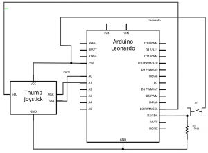
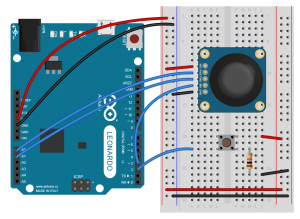
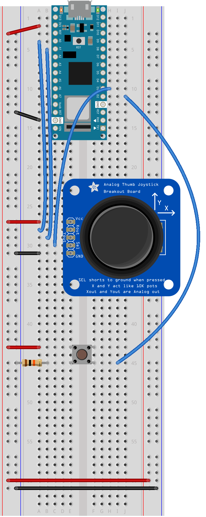
Add a thumb joystick, as shown below in Figure 13. For the Arduino Nano view, see Figure 14. For the schematic view, see Figure 11. Attach the X out to analog input 0, the Y out to analog input 1, and the select button to digital input 3.

Schematic drawing of a pushbutton and a joystick attached to an Arduino Leonardo. The pushbutton is attached to digital pin 2 on one side, and to +5 volts on the other. there is also a 10-kilohm resistor attached to digital pin 2. Its other side is attached to ground. The joystick's X out pin is attached to the Leaonardo's analog input A0. The Y out is attached to analog inpug A1. The joystick's SEL (for select) output is attached to digital pin 3. The joystick's Vcc pin is connected to +5 volts. and its ground pin is connected to ground.
Figure 12. Schematic view of a pushbutton and a joystick attached to an Arduino Leonardo
Breadboard drawing of an Arduino Leonardo connected to a pushbutton and a joystick.The pushbutton is described as in the previous breadboard drawing. The joystick is mounted with its five pins in rows 9 through 13 of the left center section of the breadboard. The body of the joystick is to the right of the pins, and the top pin is therefore the Vcc pin. A black wire connects row 13, the ground pin, to the left side ground bus. A red wire connects row 9, Vcc pin, to the left side voltage bus. A blue wire connects row 10, the X out pin, to the Leonardo's analog in pin A0. Another wire connects row 11, the Y out, to analog in A1. Yet another wire connects row 12, the Select pin, to digital pin 3.
Figure 13. Breadboard view of an Arduino Leonardo connected to a pushbutton and a joystick.
Breadboard drawing of an Arduino Nano connected to a pushbutton and a joystick. The pushbutton is described as in the previous breadboard drawing. The joystick is mounted with its five pins in rows 27 through 31 of the left center section of the breadboard. The body of the joystick is to the right of the pins, and the top pin is therefore the Vcc pin. A black wire connects row 31, the ground pin, to the left side ground bus. A red wire connects row 27, Vcc pin, to the left side voltage bus. A blue wire connects row 28, the X out pin, to the Nano's analog in pin A0. Another wire connects row 29, the Y out, to analog in A1. Yet another wire connects row 30, the Select pin, to digital pin 3.
Figure 14. Breadboard drawing of an Arduino Nano connected to a pushbutton and a joystick.

Program the module to read the pushbutton

Follow the same steps as you did in the first Mouse Control lab to read when the pushbutton on pin 2 is pressed. Your code should only print out a message when the button changes state. Similarly, set up a global variable to track whether or not you’re controlling the mouse, called mouseIsActive. Each time the pushbutton on pin 2 is pressed, change the state of this variable from false to true, just like you did in the first mouse control lab.

1
2
3
4
5
6
7
8
9
10
11
12
13
14
15
16
17
18
19
20
21
22
23
24
25
26
27
// Global variables:
int lastButtonState = LOW;            // state of the button last time you checked
boolean mouseIsActive = false;    // whether or not the Arduino is controlling the mouse
 
void setup() {
  // initialize serial communication:
  Serial.begin(9600);
  pinMode(2, INPUT);
}
 
void loop() {
  // read the first pushbutton:
  int buttonState = digitalRead(2);
 
  // if it's changed and it's high, toggle the mouse state:
  if (buttonState != lastButtonState) {
    if (buttonState == HIGH) {
      // if mouseIsActive is true, make it false;
      // if it's false, make it true:
      mouseIsActive = !mouseIsActive;
      Serial.print("Mouse control state: ");
      Serial.println(mouseIsActive);
    }
  }
  // save button state for next comparison:
  lastButtonState = buttonState;
}

Program the Leonardo to read the Joystick

Add code to the main loop to read the joystick X and Y outputs and print them.

1
2
3
4
5
6
7
8
9
10
11
12
13
14
15
16
17
18
19
20
21
22
23
24
25
26
27
28
29
30
31
32
33
34
35
36
// Global variables:
int lastButtonState = LOW;            // state of the button last time you checked
boolean mouseIsActive = false;    // whether or not the Arduino is controlling the mouse
 
void setup() {
  // initialize serial communication:
  Serial.begin(9600);
  pinMode(2, INPUT);
}
 
void loop() {
  // read the first pushbutton:
  int buttonState = digitalRead(2);
 
  // if it's changed and it's high, toggle the mouse state:
  if (buttonState != lastButtonState) {
    if (buttonState == HIGH) {
      // if mouseIsActive is true, make it false;
      // if it's false, make it true:
      mouseIsActive = !mouseIsActive;
      Serial.print("Mouse control state: ");
      Serial.println(mouseIsActive);
    }
  }
  // save button state for next comparison:
  lastButtonState = buttonState;
 
  // read the analog sensors:
  int sensor1 = analogRead(A0);
  delay(1);
  int sensor2 = analogRead(A1);
  // print their values. Remove this when you have things working:
  Serial.print(sensor1);
  Serial.print("  ");
  Serial.println(sensor2);
}

Map the X and Y output readings

The Mouse.move() command has three parameters: the horizontal movement, the vertical movement, and the scroll wheel movement. All movements are relative, so Mouse.move(1,0,0); moves one pixel to the right; Mouse.move(-1,0,0); moves one pixel to the left; Mouse.move(0,1,0); moves one pixel down; and Mouse.move(0,-1,0); moves one pixel up. Moving the mouse more than about 5 pixels in any direction is a very fast move. So the ideal range for the joystick is if it can move the cursor 5 pixels in any direction.

In order to do this, you need to scale the X and Y outputs from the default range that they return (0 to 1023) to a range from -5 to 5. You can do this using the map() function. Map takes five parameters: the input value, the range of the input value, and the desired output range, like so:

result = map(inputValue, inputMinimum, inputMaximum, outputMinimum, outputMaximum);

So, if your input range is 0 to 1023, and your output range is -5 to 5, you might map like this:

result = map(sensorReading, 0, 1023, -5, 5);

Add code to the main loop to map the X and Y outputs to a range from -5 to 5. Print the mapped values instead of the original sensor values.

1
2
3
4
5
6
7
8
9
10
11
12
// read the analog sensors:
  int sensor1 = analogRead(A0);
  delay(1);
  int sensor2 = analogRead(A1);
 
  int xAxis = map(sensor1, 0, 1023, -5, 5);
  int yAxis = map(sensor2, 0, 1023, -5, 5);
 
 // print their values. Remove this when you have things working:
  Serial.print(xAxis);
  Serial.print("  ");
  Serial.println(yAxis);

NOTE: If your joystick defaults to -1 at rest on one axis or both, try adding 1 to the result of the map command. Try different output ranges and see what they do.

When you run this sketch, you should see the Mouse Control State message once every time you press the first pushbutton, and the values of the X and Y axes of the joystick, mapped to a range of -5 to 5. You still need to add in the select button on the joystick, however.

Add code to listen for the Joystick Select Button

The joystick select button is a digital input, but it’s wired differently than the buttons you saw in the Digital Lab or the Mouse Control With Pushbuttons Lab.

Note on pullup vs. pulldown resistors

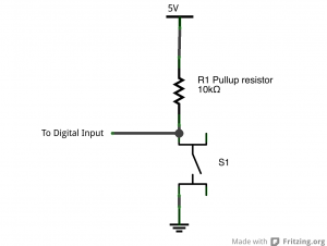
It is, in fact, wired to connect to ground when you press it. To read it, then, you’d still use digitalWrite(), but you’d expect it to go low when pressed instead of high. And instead of a pulldown resistor like you’ve used in those other two labs, you’d use a pullup resistor, so that it’s connected to 5V when the switch is not open.

You can see the schematic for a pullup resistor circuit below in Figure 12.

Schematic drawing of a pushbutton and a pullup resistor. A 10-kilohm resistor is connected to +5 volts. The other side of the resistor is connected to a pushbutton. The other side of the pushbutton is connected to ground. The junction where the resistor and the pushbutton meet is labeled "to digital input"
Figure 15: Schematic view of a pushbutton and a pullup resistor.

The Arduino has built-in pullup resistors that you can use on the digital inputs. Most microcontrollers have these. When you set the pin to be an input using the pinMode() command, use the parameter INPUT_PULLUP instead of INPUT. This will activate the built-in pullup resistor on that pin, so you only have to attach a switch between the pin and ground.

The advantage of connecting your pushbutton to ground instead of 5V is that you can use the internal pullup resistor instead of having to add an external resistor. The disadvantage is that your switch logic is inverted: HIGH means the switch is open, and LOW means it is closed. Most of the time you can wire your switches either way, but when you have a switch that’s already wired to ground like the select button in the joystick, you have to use the internal pullups and inverted logic.

Previously, you wired the select button to digital input 3. To read the select button in this sketch, add a pinMode command to the setup that makes it an INPUT_PULLUP. Then in the main loop, check if the mosueIsActive variable is true. If it is, then use digitalRead() to read the select button and store it in a local variable called button2State.

Add the following at the end of the setup command:

1
2
// make pin 3 an input, using the built-in pullup resistor:
 pinMode(3, INPUT_PULLUP);

Then at the end of the loop, add the following code:

1
2
3
4
if (mouseIsActive == true) {
    // read the second pushbutton:
   int button2State = digitalRead(3);
}

The select button’s behavior should be like the mouse control pushbutton’s behavior: you only want something to happen when it changes. When the select button changes from off to on, you want it to perform a mouse click. When it changes from on to off, you want it to perform a mouse release. So you need to check for when the select button changes, just like you do with the other pushbutton.

To check for the select button to change, set up a global variable called lastButton2State to save its previous state. Then set up an if statement in the main loop after you read it to see if the current state and the previous state are different. If they are different, add another if statement to see if the current state is HIGH or LOW. If it’s LOW, then print “Mouse press” (remember,its logic is inverted). If the current state is HIGH, then print “mouse press”.

This block of code will look a lot like the code you used for Mouse Control to track the state change of the pushbutton on pin 2.

Add the following line before the setup command:

1
int lastButton2State = LOW;       // state of the other button last time you checked

Then inside the if statement that you added to check the mouseIsActive variable, add the following code (the if statement is shown here too):

1
2
3
4
5
6
7
8
9
10
11
12
13
14
15
16
if (mouseIsActive == true) {
    // read the second pushbutton:
    int button2State = digitalRead(3);
 
    // if it's changed and it's high, toggle the mouse state:
    if (button2State != lastButton2State) {
      if (button2State == LOW) {
        Serial.println("mouse pressed");
      }
      else {
        Serial.println("mouse released");
      }
    }
    // save second button state for next comparison:
    lastButton2State = button2State;
  }

When you run this code, you should see the words “mouse pressed” once when you press the select button, and “mouse released” when you release the select button. If it prints continually, you have an error.

When you’ve got that working, you’re ready to take control of the mouse.

Add commands to control the mouse

The Mouse.begin() command is called in the setup. It initializes mouse control from your Leonardo.

Include the Mouse library at the top of your sketch. Modify the setup by adding the command Mouse.begin(). Then, in the loop where check if mouseIsActive is true, add Mouse.move commands to move as needed. Also add Mouse.press() when the select button is pressed, and Mouse.release() when it is released.

At the end of the setup(), add the following:

1
2
3
#include "Mouse.h"
// initialize mouse control:
Mouse.begin();

Then in the main loop, add the following lines to the if statement that checks mouseIsActive:

1
2
3
4
5
6
7
8
9
10
11
12
13
14
15
16
17
if (mouseIsActive == true) {
   Mouse.move(xAxis, yAxis, 0);
 
   // read the second pushbutton:
   int button2State = digitalRead(3);
 
   // if it's changed and it's high, toggle the mouse state:
   if (button2State != lastButton2State) {
     if (button2State == LOW) {
       Serial.println("mouse pressed");
       Mouse.press();
     }
     else {
       Serial.println("mouse released");
       Mouse.release();
     }
   }

That’s the whole sketch. When you run this, press the mouse control pushbutton, then move the joystick and press the select button. You should have full mouse control.

The full sketch for this can be found on the phys comp github repository, called MouseMoveSimpleJoystick.

In this sketch, you can see the value of scaling an analog sensor’s readings to match the output range you need. Since the joystick potentiometers are at rest in the middle of their range, scaling them from -5 to 5 gives you easy control of the mouse movement, which is relative. You can also see how reading the state change of a digital input is important. You’re doing it for two different buttons in this sketch.

Lab: Mouse Control With Pushbuttons

In this lab, you’ll build an alternative computer mouse using an Arduino Leonardo using pushbuttons to move the mouse left, right, up and down. You’ll see the difference between reading a digital input continually and reading for a change of state.

Introduction

In this lab, you’ll build an alternative computer mouse using an Arduino Leonardo using pushbuttons to move the mouse left, right, up and down. You’ll see the difference between reading a digital input continually and reading for a change of state.

What You’ll Need to Know

To get the most out of this lab, you should be familiar with the following concepts. You can check how to do so in the links below:

Things You’ll Need

Figures 1-5 show the parts you’ll need for this exercise. Click on any image for a larger view.

A short solderless breadboard with two rows of holes along each side. There are no components mounted on the board.
Figure 1. A solderless breadboard.
Photo of an Arduino Nano 33 IoT module. The USB connector is at the top of the image, and the physical pins are numbered in a U-shape from top left to bottom left, then from bottom right to top right.
Figure 2. Arduino Nano 33 IoT
Three 22AWG solid core hookup wires. Each is about 6cm long. The top one is black; the middle one is red; the bottom one is blue. All three have stripped ends, approximately 4 to 5mm on each end.
Figure 3. 22AWG solid core hookup wires.
Resistors. Shown here are 220-ohm resistors. You can tell this because they have two red and one brown band, followed by a gold band.
Figure 4. Resistors. Shown here are 220-ohm resistors.  For this exercise, you’ll need 10-kilohm resistors (10K resistors are brown-black-orange. For more, see this resistor color calculator)
Photo of four breadboard-mounted pushbuttons
Figure 5. Pushbuttons.  You’ll need 5 switches for this exercise. Any switches will do the job as well.

About mouse control

NOTE: The sketches contained in this lab will cause the Arduino Leonardo to take control of your mouse. Make sure they’re working properly before you add the mouse commands. The example doesn’t introduce the mouse commands until the end of the lab. Instead, messages are printed to the serial monitor to tell you what should happen. When you’ve run this and seen the serial messages occurring when you think they should, then you can add the mouse commands safely.

The sketches here will work on an Uno until you add the mouse commands. So you can test this on an Uno simply by commenting out any line that says Mouse.begin() or Mouse.move().

Note on Mouse, Keyboard, and Serial Ports

The Mouse and Keyboard libraries on the SAMD boards (MKRZero, MKR1xxx, Nano 33IoT) have an unusual behavior: using them changes the serial port enumeration. When you include the Keyboard library in a sketch, your board’s serial port number will change. For example, on MacOS, if the port number is /dev/cu.usbmodem14101, then adding the Keyboard library will change it to /dev/cu.usbmodem14102. Removing the Keyboard library will change it back to /dev/cu.usbmodem14101. Similarly, if you double-tap the reset button to put the board in bootloader mode, the serial port will re-enumerate to its original number.

Windows and HID Devices

You may have trouble getting these sketches to work on Windows. On Windows, the default Arduino drivers must be uninstalled so the system can recognize the Arduino as both serial device and HID device. Read this issue and follow the instructions there.

Recovering From a Runaway HID (Mouse or Keyboard) Sketch

Programs which control your keyboard and mouse can make development difficult or impossible if you make a mistake in your code. If you create a mouse or keyboard example that doesn’t do what you want it to, and you need to reprogram your microcontroller to stop the program, do this:

Open a new blank sketch.

This sketch is your recovery:

1
2
3
4
5
6
void setup() {
 
}
void loop() {
 
}

Programming the board with this blank sketch removes your mistaken sketch and gives you control again. To do this, however, you need the current sketch to stop running. So:

Put the microcontroller in bootloader mode and upload the blank sketch

On the SAMD boards, you can do this by double-tapping the reset button. The on-board LED will begin glowing, and the bootloader will start so that you get a serial port enumeration, but the sketch won’t run. On the Leonardo and other 32U4-based boards, hold the reset down until you’ve given the upload command. The 32U4 bootloader will take a few seconds before it starts the sketch, so the uploader can take command and load your blank sketch.

Once you’ve got the blank sketch on the board, review the logic of your mistaken Keyboard or Mouse sketch and find the problem before uploading again.

Prepare the breadboard

Connect power and ground on the breadboard to power and ground from the microcontroller. On the Arduino module, use the 5V and any of the ground connections as shown below in Figure 6. If using the Arduino Nano connect the 3.3V and ground pins according to Figure 7.

An Arduino Leonardo on the left connected to a solderless breadboard, right. The Leonardo's 5V output hole is connected to the red column of holes on the far left side of the breadboard. The Leonardo's ground hole is connected to the blue column on the left of the board. The red and blue columns on the left of the breadboard are connected to the red and blue columns on the right side of the breadboard with red and black wires, respectively. These columns on the side of a breadboard are commonly called the buses. The red line is the voltage bus, and the black or blue line is the ground bus.
Figure 6. An Arduino Leonardo on the left connected to a solderless breadboard, right.
Arduino Nano on a breadboard.
Figure 7. Breadboard view of an Arduino Nano mounted on a breadboard.

Figure 7. Breadboard view of an Arduino Nano connected to a breadboard. The +3.3 volts and ground pins of the Arduino are connected by red and black wires, respectively, to the left side rows of the breadboard. +3.3 volts is connected to the left outer side row (the voltage bus) and ground is connected to the left inner side row (the ground bus). The side rows on the left are connected to the side rows on the right using red and black wires, respectively, creating a voltage bus and a ground bus on both sides of the board.


Made with Fritzing

Add a pushbutton

Attach a pushbutton to digital pin 2 as shown below in Figure 9. See Figure 10 for Arduino Nano. See Figure 8 for the schematic view. Connect one side of the pushbutton to 5 volts, and the other side of the pushbutton to a 10-kilohm resistor. Connect the other end of the resistor to ground. Connect the junction where the pushbutton and the resistor meet to digital pin 2. (For more on this digital input circuit, see the Digital Input Lab).

Schematic drawing of an Arduino Leonardo connected to a pushbutton and two voltage divider inputs. The pushbutton is connected as described in the schematic above. On the left side of the board, two photoresistors are connected to +5 volts. The other sides of the photoresistors are connected to analog inputs A0 and A1, respectively. Two 10-kilohm resistors are also connected to those pins. The other sides of the fixed resistors are connected to ground.
Figure 8. Schematic view of an Arduino Leonardo connected to a pushbutton.
Breadboard drawing of an Arduino Leonardo connected to a pushbutton. The pushbutton straddles the center divide of the breadboard in rows 20 through 22. A red wire connects row 20 on the right center side to the right side voltage bus. A 10-kilohm resistor connects row 22 on the right center side to row 26 on the same side. A black wire connects from row 26 to the ground bus on the right side. A blue wire connects row 22 on the left center side of the board to digital p
Figure 9. Breadboard view of an Arduino Leonardo connected to a pushbutton.

Breadboard view of an Arduino Nano connected to a pushbutton. The +5 volts and ground pins of the Arduino are connected by red and black wires, respectively, to the left side rows of the breadboard. +5 volts is connected to the left outer side row (the voltage bus) and ground is connected to the left inner side row (the ground bus). The side rows on the left are connected to the side rows on the right using red and black wires, respectively, creating a voltage bus and a ground bus on both sides of the board. The pushbutton is mounted across the middle divide of the solderless breadboard. A 10-kilohm resistor connects from the same row as pushbutton's bottom left pin to the ground bus on the breadboard. There is a wire connecting to digital pin 2 from the same row that connects the resistor and the pushbutton. The top left pin of the pushbutton is connected to +3.3V.
Figure 10. Breadboard view of an Arduino Nano connected to a pushbutton.

Figure 10. Breadboard view of an Arduino Nano connected to a pushbutton. The +3.3 volts and ground pins of the Arduino are connected by red and black wires, respectively, to the left side rows of the breadboard. +3.3 volts is connected to the left outer side row (the voltage bus) and ground is connected to the left inner side row (the ground bus). The side rows on the left are connected to the side rows on the right using red and black wires, respectively, creating a voltage bus and a ground bus on both sides of the board. The pushbutton is mounted across the middle divide of the solderless breadboard. A 10-kilohm resistor connects from the same row as pushbutton’s bottom left pin to the ground bus on the breadboard. There is a wire connecting to digital pin 2 from the same row that connects the resistor and the pushbutton. The top left pin of the pushbutton is connected to +3.3V.


Add four more pushbuttons

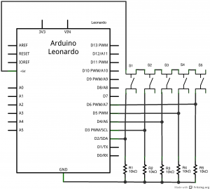
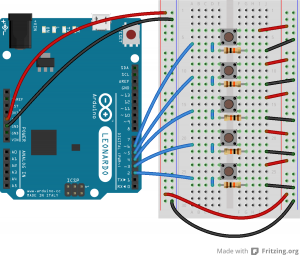
Repeat the last step, connecting four more pushbuttons to pins 3 through 6 as shown below in Figure 12. See Figure 11 for the schematic view. See Figure 13 for Arduino Nano.

Schematic drawing of a pushbutton and a joystick attached to an Arduino Leonardo. The pushbutton is attached to digital pin 2 on one side, and to +5 volts on the other. there is also a 10-kilohm resistor attached to digital pin 2. Its other side is attached to ground. Four other pushbuttons, with pulldown resistors like this one, are connected to pins 3 through 6 in the same way.
Figure 11. Schematic view of an Arduino Leonardo connected to five pushbutton.
Breadboard drawing of an Arduino Leonardo connected to five pushbuttons. The pushbutton from the previous breadboard drawing has been rearranged, and new buttons have been added, as follows. The pushbuttons straddle the center divide of the breadboard in rows 4-6, 9-11, 14-16, 19-21, and 24-26, respectively. 10-kilohm resistors straddle the center divide in rows 7, 12, 17, and 22, respectively. Each resistor's row on the left center side is connected to the row above it with a wire, thus connecting the pushbuttons and the resistors. Each resistor's row on the right center side is connected to the right side ground bus with a black wire. Each pushbutton's upper row (that is, rows 4, 9, 14, 19, and 23) on the right center side is connected to the right side voltage bus with a red wire. The junction rows, that is, rows 6, 11, 16, 21, and 26, are connected to digital inputs 2 through 6 on the Leonardo, respectively, with blue wires
Figure 12. Breadboard view of an Arduino Leonardo connected to five pushbuttons.

Breadboard drawing of an Arduino Nano connected to five pushbuttons. The pushbuttons straddle the center divide of the breadboard in rows 20-22, 25-27, 30-32, 35-37, and 40-42, respectively. 10-kilohm resistors connect the left side of each pushbutton to the breadboard's GND bus at rows 22, 27, 32, 37, 42. Blue wires connect the right side of each pushbutton at pins 22, 27, 32, 37, 42 to the arduino digital pins 2-6 respectively. Red wires connect the left side of each pushbutton to the voltage bus at rows 20, 25, 30, 35, 40
Figure 13. Breadboard drawing of an Arduino Nano connected to five pushbuttons.

Figure 13. Breadboard drawing of an Arduino Nano connected to five pushbuttons at digital pins 2-6 respectively.


Program the module to read the pushbutton

Follow the same steps as you did in the first Mouse Control lab to read when the pushbutton on pin 2 is pressed. Your code should only print out a message when the button changes state.

Similarly, set up a global variable to track whether or not you’re controlling the mouse, called mouseIsActive. Each time the pushbutton on pin 2 is pressed, change the state of this variable from false to true, just like you did in the first mouse control lab.

1
2
3
4
5
6
7
8
9
10
11
12
13
14
15
16
17
18
19
20
21
22
23
24
25
26
27
// Global variables:
int lastButtonState = LOW;            // state of the button last time you checked
boolean mouseIsActive = false;    // whether or not the Arduino is controlling the mouse
 
void setup() {
  // initialize serial communication:
  Serial.begin(9600);
  pinMode(2, INPUT);
}
 
void loop() {
  // read the first pushbutton:
  int buttonState = digitalRead(2);
 
  // if it's changed and it's high, toggle the mouse state:
  if (buttonState != lastButtonState) {
    if (buttonState == HIGH) {
      // if mouseIsActive is true, make it false;
      // if it's false, make it true:
      mouseIsActive = !mouseIsActive;
      Serial.print("Mouse control state: ");
      Serial.println(mouseIsActive);
    }
  }
  // save button state for next comparison:
  lastButtonState = buttonState;
}

Activate the other four buttons

The other four pushbuttons are intended to control the mouse movement: the button on pin 3 should move the mouse right; the one on pin 4 should move it left; the one on pin 5 should move it down; and the one on pin 6 should move it up. If the user holds the button down, the mouse should continue to move in the corresponding direction.

To make this happen, you need to read the buttons’ states. You don’t need to tell when they change from off to on, in this case. You just need to know that they are on. But you shouldn’t do anything unless the mouseIsActive variable is true.

Add code to the setup to set pins 3 through 6 to input using the pinMode command. Then add code to the loop to read whether the mouseIsActive variable is true. If it is, read the four other pushbuttons. For each one, check if it’s high, and if so, print the letter of the direction you’re moving, U, R, L, or D.

1
2
3
4
5
6
7
8
9
10
11
12
13
14
15
16
17
18
19
20
if (mouseIsActive) {
    // read the other buttons:
    int button2State = digitalRead(3);
    int button3State = digitalRead(4);
    int button4State = digitalRead(5);
    int button5State = digitalRead(6);
 
    if (button2State == HIGH) {
      Serial.println("R");
    }
    if (button3State == HIGH) {
       Serial.println("L");
    }
    if (button4State == HIGH) {
       Serial.println("D");
    }
    if (button5State == HIGH) {
       Serial.println("U");
    }
  }

When you run this sketch, you should see the Mouse Control State message once every time you press the first pushbutton, and the letters R, L, U, or D continuously when you hold down any of the other four pushbuttons. When you’ve got that working, you’re ready to take control of the mouse.

Add commands to control the mouse

The Mouse.begin() command is called in the setup. It initializes mouse control from your Leonardo.

The Mouse.move() command has three parameters: the horizontal movement, the vertical movement, and the scroll wheel movement. All movements are relative, so Mouse.move(1,0,0); moves one pixel to the right; Mouse.move(-1,0,0); moves one pixel to the left; Mouse.move(0,1,0); moves one pixel down; and Mouse.move(0,-1,0); moves one pixel up.

Include the Mouse library at the top of your code. Then modify the setup by adding the command Mouse.begin(). Then, in the loop where you print L, R, U, or D add Mouse.move commands to move as needed.

1
2
3
4
5
6
7
8
9
10
11
12
13
14
15
16
17
18
19
20
21
22
23
24
25
26
27
28
29
30
31
32
33
34
35
36
37
38
39
40
41
42
43
44
45
46
47
48
49
50
51
52
53
54
55
56
57
58
59
60
#include "Mouse.h"
// Global variables:
int lastButtonState = LOW;        // state of the button last time you checked
boolean mouseIsActive = false;    // whether or not the Arduino is controlling the mouse
 
void setup() {
  // initialize mouse control:
  Mouse.begin();
  // initialize serial communication:
  Serial.begin(9600);
  // make pin 2 through 6 inputs:
  pinMode(2, INPUT);
  pinMode(3, INPUT);
  pinMode(4, INPUT);
  pinMode(5, INPUT);
  pinMode(6, INPUT);
}
 
void loop() {
  // read the first pushbutton:
  int buttonState = digitalRead(2);
 
  // if it's changed and it's high, toggle the mouse state:
  if (buttonState != lastButtonState) {
    if (buttonState == HIGH) {
      // if mouseIsActive is true, make it false;
      // if it's false, make it true:
      mouseIsActive = !mouseIsActive;
    }
  }
  // save button state for next comparison:
  lastButtonState = buttonState;
 
  // if the mouse is active, and any button is pressed,
  // move the mouse in the corresponding direction:
  if(mouseIsActive) {
    // read the other buttons:
    int button2State = digitalRead(3);
    int button3State = digitalRead(4);
    int button4State = digitalRead(5);
    int button5State = digitalRead(6);
 
    if (button2State == HIGH) {
      Serial.println("R");
      Mouse.move(2, 0, 0);      // move right
    }
    if (button3State == HIGH) {
      Serial.println("L");
      Mouse.move(-2, 0, 0);     // move left
    }
    if (button4State == HIGH) {
      Serial.println("D");
      Mouse.move(0, 2, 0);      // move down
    }
    if (button5State == HIGH) {
      Serial.println("U");
      Mouse.move(0, -2, 0);      // move up
    }
  }
}

That’s the whole sketch. When you run this, press the button to enable or disable mouse control, then press any of the other four buttons, and the mouse will move in the appropriate direction.

The full sketch for this can be found on the phys comp github repository, called MouseMoveSimpleButtons.

You can see from this sketch the difference between reading a digital input to look for the state change (the button on pin 2) and reading a digital input just to see the current state (buttons on pins 3 through 6). When you’re designing a response that can repeat infinitely, you can just read the current state. But when you’re designing a response that should happen just once, you need to determine when the button changes state.

Next, try the Mouse Control With Joystick lab.

Lab: Mouse Control

In this lab, you’ll build an alternative computer mouse using any of the USB-native boards. You’ll also learn some techniques for determining when a user takes a physical action.

Introduction

In this lab, you’ll build an alternative computer mouse using any of the USB-native boards (the MKR series, the Due, the Leonardo, the Micro, and the Feather M0 series all fit this requirement). You’ll also learn some techniques for determining when a user takes a physical action. In the Digital Lab and Analog Lab, you learned how to read the input from a digital or analog input, but you didn’t learn anything about how to interpret the stream of data as an event. There are a few everyday physical interactions that are fairly easy to pick out from a stream of data. You’ll see a few of them in this lab.

Keyboard and Mouse are examples of the USB Human Interface Device (HID) profile. There is another library, the HID-project library, which extends Keyboard and Mouse to do things like using the consumer keys (alternate functions of the F-keys), power key, and so forth.

This lab should should work on SAMD Arduino boards (MKR series, Nano 33 IoT), as well as the Leonardo, Due, and other USB-native boards.

What You’ll Need to Know

To get the most out of this lab, you should be familiar with the following concepts. You can check how to do so in the links below:

Things You’ll Need

Figures 1-6 show the parts you’ll need for this exercise. Click on any image for a larger view.

A short solderless breadboard with two rows of holes along each side. There are no components mounted on the board.
Figure 1. A solderless breadboard.
Photo of an Arduino Nano 33 IoT module. The USB connector is at the top of the image, and the physical pins are numbered in a U-shape from top left to bottom left, then from bottom right to top right.
Figure 2. Arduino Nano 33 IoT
Three 22AWG solid core hookup wires. Each is about 6cm long. The top one is black; the middle one is red; the bottom one is blue. All three have stripped ends, approximately 4 to 5mm on each end.
Figure 3. 22AWG solid core hookup wires.
Resistors. Shown here are 220-ohm resistors. You can tell this because they have two red and one brown band, followed by a gold band.
Figure 4. Resistors. Shown here are 220-ohm resistors.  For this exercise, you’ll need 10-kilohm resistors (10K resistors are brown-black-orange. For more, see this resistor color calculator)
A pushbutton with two wires soldered one to each of the button's contacts.
Figure 5. A pushbutton with two wires soldered one to each of the button’s contacts. Any switch will do the job as well.
Photocell, or light-dependent resistor. This component has a round top and two wire legs. You measure the resistance between the two legs and expose the top to a varying light source in order to vary the resistance between the two legs.
Figure 6. Photocell, or light-dependent resistor Any analog sensor will do the job for this lab.

About mouse control

NOTE: The sketches contained in this lab will cause the Arduino Leonardo to take control of your mouse. Make sure they’re working properly before you add the mouse commands. The example doesn’t introduce the mouse commands until the end of the lab. Instead, messages are printed to the serial monitor to tell you what should happen. When you’ve run this and seen the serial messages occurring when you think they should, then you can add the mouse commands safely.

The sketches here will work on an Uno until you add the mouse commands. So you can test this on an Uno or any board that’s not USB-native simply by commenting out the Mouse.h include at the top of the code below, and any line that says Mouse.begin() or Mouse.move().

Note on Mouse, Keyboard, and Serial Ports

The Mouse and Keyboard libraries on the SAMD boards (MKRZero, MKR1xxx, Nano 33IoT) have an unusual behavior: using them changes the serial port enumeration. When you include the Keyboard library in a sketch, your board’s serial port number will change. For example, on MacOS, if the port number is /dev/cu.usbmodem14101, then adding the Keyboard library will change it to /dev/cu.usbmodem14102. Removing the Keyboard library will change it back to /dev/cu.usbmodem14101. Similarly, if you double-tap the reset button to put the board in bootloader mode, the serial port will re-enumerate to its original number.

Windows and HID Devices

You may have trouble getting these sketches to work on Windows. On Windows, the default Arduino drivers must be uninstalled so the system can recognize the Arduino as both serial device and HID device. Read this issue and follow the instructions there.

Recovering From a Runaway HID (Mouse or Keyboard) Sketch

Programs which control your keyboard and mouse can make development difficult or impossible if you make a mistake in your code. If you create a mouse or keyboard example that doesn’t do what you want it to, and you need to reprogram your microcontroller to stop the program, do this:

Open a new blank sketch.

This sketch is your recovery:

1
2
3
4
5
6
void setup() {
 
}
void loop() {
 
}

Programming the board with this blank sketch removes your mistaken sketch and gives you control again. To do this, however, you need the current sketch to stop running. So:

Put the microcontroller in bootloader mode and upload the blank sketch

On the SAMD boards, you can do this by double-tapping the reset button. The on-board LED will begin glowing, and the bootloader will start so that you get a serial port enumeration, but the sketch won’t run. On the Leonardo and other 32U4-based boards, hold the reset down until you’ve given the upload command. The 32U4 bootloader will take a few seconds before it starts the sketch, so the uploader can take command and load your blank sketch.

Once you’ve got the blank sketch on the board, review the logic of your mistaken Keyboard or Mouse sketch and find the problem before uploading again.

Prepare the breadboard

Connect power and ground on the breadboard to power and ground from the microcontroller. On the Arduino module, use the 5V and any of the ground connections.

In Figure 7 you see an Arduino Leonardo on the left connected to a solderless breadboard, right. The Leonardo’s 5V output hole is connected to the red column of holes on the far left side of the breadboard. The Leonardo’s ground hole is connected to the blue column on the left of the board. The red and blue columns on the left of the breadboard are connected to the red and blue columns on the right side of the breadboard with red and black wires, respectively. These columns on the side of a breadboard are commonly called the buses. The red line is the voltage bus, and the black or blue line is the ground bus. See Figure 8 for the breadboard view with Arduino Nano.

An Arduino Leonardo on the left connected to a solderless breadboard, right. The Leonardo's 5V output hole is connected to the red column of holes on the far left side of the breadboard. The Leonardo's ground hole is connected to the blue column on the left of the board. The red and blue columns on the left of the breadboard are connected to the red and blue columns on the right side of the breadboard with red and black wires, respectively. These columns on the side of a breadboard are commonly called the buses. The red line is the voltage bus, and the black or blue line is the ground bus.

Figure 7: An Arduino Leonardo on the left connected to a solderless breadboard, right.
Arduino Nano on a breadboard.
Figure 8 Breadboard view of Arduino Nano mounted on a breadboard.

Figure 8. Breadboard view of an Arduino Nano connected to a breadboard. The +3.3 volts and ground pins of the Arduino are connected by red and black wires, respectively, to the left side rows of the breadboard. +3.3 volts is connected to the left outer side row (the voltage bus) and ground is connected to the left inner side row (the ground bus). The side rows on the left are connected to the side rows on the right using red and black wires, respectively, creating a voltage bus and a ground bus on both sides of the board.

Made with Fritzing


Add a pushbutton

Attach a pushbutton to digital pin 2. Connect one side of the pushbutton to 5 volts, and the other side of the pushbutton to a 10-kilohm resistor. Connect the other end of the resistor to ground. Connect the junction where the pushbutton and the resistor meet to digital pin 2. (For more on this digital input circuit,see the Digital Input Lab)

In Figure 9 and Figure 10 you see a schematic drawing and a breadboard drawing of an Arduino Leonardo connected to a pushbutton. Figure 11 shows the Nano 33 IoT version. The pushbutton straddles the center divide of the breadboard in rows 20 through 22. A red wire connects row 20 on the right center side to the right side voltage bus. A 10-kilohm resistor connects row 22 on the right center side to row 26 on the same side. A black wire connects from row 26 to the ground bus on the right side. A blue wire connects row 22 on the left center side of the board to digital pin 2. See Figure 11 for the breadboard view with Arduino Nano.

Schematic drawing of an Arduino Leonardo connected to a pushbutton. The pushbutton is connected on one side to digital pin 2. Thje other side is connected to +5 volts. a 10-kilohm resistor is connected to the junction where the pushbutton meets pion 2. The other side of the resistor is connected to ground.
Figure 9. Schematic view of an Arduino Leonardo connected to a pushbutton.
Breadboard drawing of an Arduino Leonardo connected to a pushbutton. The pushbutton straddles the center divide of the breadboard in rows 20 through 22. A red wire connects row 20 on the right center side to the right side voltage bus. A 10-kilohm resistor connects row 22 on the right center side to row 26 on the same side. A black wire connects from row 26 to the ground bus on the right side. A blue wire connects row 22 on the left center side of the board to digital pin 2.

Figure 10: Breadboard view of an Arduino Leonardo connected to a pushbutton.

Breadboard view of an Arduino Nano connected to a pushbutton. The +5 volts and ground pins of the Arduino are connected by red and black wires, respectively, to the left side rows of the breadboard. +5 volts is connected to the left outer side row (the voltage bus) and ground is connected to the left inner side row (the ground bus). The side rows on the left are connected to the side rows on the right using red and black wires, respectively, creating a voltage bus and a ground bus on both sides of the board. The pushbutton is mounted across the middle divide of the solderless breadboard. A 10-kilohm resistor connects from the same row as pushbutton's bottom left pin to the ground bus on the breadboard. There is a wire connecting to digital pin 2 from the same row that connects the resistor and the pushbutton. The top left pin of the pushbutton is connected to +3.3V.
Figure 11. Breadboard view of an Arduino Nano connected to a pushbutton.

Figure 11. Breadboard view of an Arduino Nano connected to a pushbutton. The +3.3 volts and ground pins of the Arduino are connected by red and black wires, respectively, to the left side rows of the breadboard. +3.3 volts is connected to the left outer side row (the voltage bus) and ground is connected to the left inner side row (the ground bus). The side rows on the left are connected to the side rows on the right using red and black wires, respectively, creating a voltage bus and a ground bus on both sides of the board. The pushbutton is mounted across the middle divide of the solderless breadboard. A 10-kilohm resistor connects from the same row as pushbutton’s bottom left pin to the ground bus on the breadboard. There is a wire connecting to digital pin 2 from the same row that connects the resistor and the pushbutton. The top left pin of the pushbutton is connected to +3.3V.


Add two analog inputs

Attach a photoresistor to 5 volts. Attach a 10-kilohm resistor from the other side of the photoresistor to ground. Attach the junction where the photocell and the resistor meet to analog input 0. Do the same for analog input 1. You can use any variable resistor in place of the photoresistors: flex sensors, force-sensing resistors, or whatever feels good to you.

In Figure 12 and Figure 13 you see a schematic drawing and a breadboard drawing of an Arduino Leonardo connected to a pushbutton and two voltage divider inputs. The pushbutton is connected as described in the previous breadboard drawing. Two photoresistors are mounted in the right center section of the breadboard. The first is connected to rows 2 and 5. The second is connected to rows 11 and 14. Rows 2 and 11 are also connected to the right side voltage bus through red wires. Two 10-kilohm resistors are also mounted in the right center section. The first is connected to rows 5 and 9, and the second is connected to rows 14 and 18. Rows 9 and 18 are connected to the right side ground bus. The four resistors thus form two voltage dividers. A blue wire extends from the middle of each divider to the analog pins. The first goes from row 5 to pin A0, and the second from row 14 to pin A1. See Figure 14 for the breadboard view with Arduino Nano.

Schematic drawing of an Arduino Leonardo connected to a pushbutton and two voltage divider inputs. The pushbutton is connected as described in the schematic above. On the left side of the board, two photoresistors are connected to +5 volts. The other sides of the photoresistors are connected to analog inputs A0 and A1, respectively. Two 10-kilohm resistors are also connected to those pins. The other sides of the fixed resistors are connected to ground.
Figure 12. Schematic view of an Arduino Leonardo connected to a pushbutton.
Breadboard drawing of an Arduino Leonardo connected to a pushbutton and two voltage divider inputs. The pushbutton is connected as described in the previous breadboard drawing. Two photoresistors are mounted in the right center section of the breadboard. The first is connected to rows 2 and 5. The second is connected to rows 11 and 14. Rows 2 and 11 are also connected to the right side voltage bus through red wires. Two 10-kilohm resistors are also mounted in the right center section. The first is connected to rows 5 and 9, and the second is connected to rows 14 and 18. Rows 9 and 18 are connected to the right side ground bus. The four resistors thus form two voltage dividers. A blue wire extends from the middle of each divider to the analog pins. The first goes from row 5 to pin A0, and the second from row 14 to pin A1.
Figure 13: Breadboard view of an Arduino Leonardo connected to a pushbutton and two voltage divider circuits.

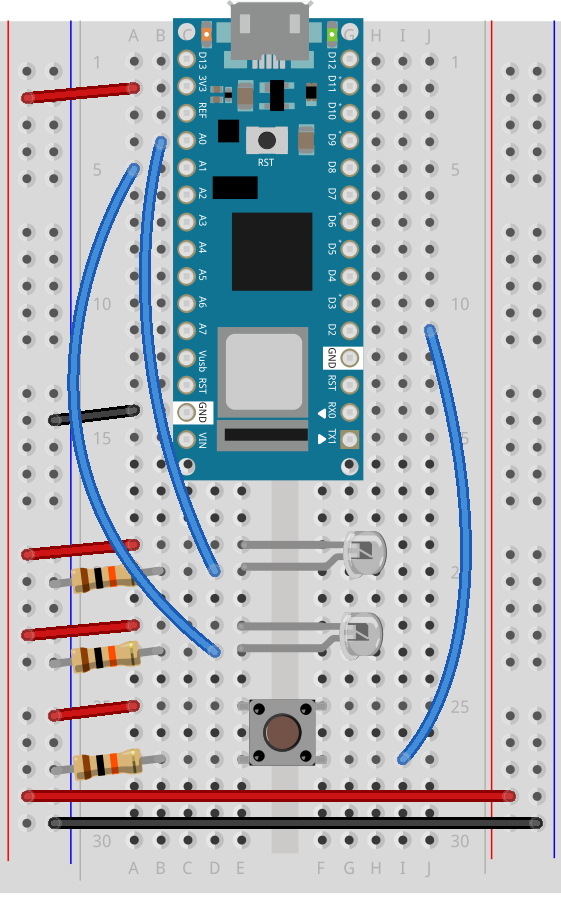
Breadboard drawing of an Arduino Nano connected to a pushbutton and two phototransistors. The pushbutton is connected as described in the previous breadboard drawing. Two phototransistors are mounted in the left center section of the breadboard. The first is connected to rows 19 and 20. The second is connected to rows 22 and 23. The short legs of the phototransistors are in Rows 19 and 22 and are connected to the left side voltage bus through red wires. The longer legs of each phototransistor are connected to rows 20 and 23 respectively. These rows also each connect a 10-kilohm resistor to the left side ground bus. Rows 20 and 23 also each connect a blue wire to the analog pins of the Arduino Nano. The first goes from row 20 to pin A0, and the second from row 23 to pin A1.
Figure 14. Breadboard drawing of an Arduino Nano connected to a pushbutton and two phototransistors.

Figure 14. Breadboard drawing of an Arduino Nano connected to a pushbutton and two phototransistors. The pushbutton connects remain the same as described in the previous diagram. The short legs of the phototransistors connect to the voltage bus. The longer legs of each phototransistor each connect a 10-kilohm resistor to the ground bus and a blue wire to the analog pins of the Arduino Nano, the first goes to pin A0, and the second to pin A1.


Program the module to read the pushbutton

In the Digital Lab you learned how to read a pushbutton using the digitalRead() command. To tell when a pushbutton is pushed, you need to determine when the button’s state changes from off to on. With the pushbutton wired as you have it here, its state will change from 0 to 1. In order to know that, you need to know not only what the current state of the button is, but you also need to remember the state of the button the previous time you read it.

To do this, set up a global variable to store the button’s previous state. Initialize the button in your program’s setup() function using the pinMode() command. Then, in the loop() function, write a block of code that reads the button and compares its state to the previous state variable. To do this, you need to read the button, check the current button state against the last state, then save the current state of the button in a variable for the next time through the loop like so:

1
2
3
4
5
6
7
8
9
10
11
12
13
14
15
16
17
18
19
int lastButtonState = LOW;        // state of the button last time you checked
 
void setup() {
  // make pin 2 an input:
  pinMode(2, INPUT);
}
 
void loop() {
  // read the pushbutton:
  int buttonState = digitalRead(2);
 
  // check if the current button state is different than the last state:
  if (buttonState != lastButtonState) {
     // do stuff if it is different here
  }
 
  // save button state for next comparison:
  lastButtonState = buttonState;
}

If buttonState is not equal to lastButtonState, then the button has changed. Then you want to check if the current state is HIGH. If it is, then you know the button has changed from low to high. That means your user pressed it. Print out a message to that effect.

1
2
3
4
5
6
7
8
9
10
11
12
13
14
15
16
17
18
19
20
21
22
int lastButtonState = LOW;        // state of the button last time you checked
 
void setup() {
  // initialize serial communication:
  Serial.begin(9600);
  // make pin 2 an input:
  pinMode(2, INPUT);
}
 
void loop() {
  // read the pushbutton:
  int buttonState = digitalRead(2);
 
  // if it's changed and it's high, toggle the mouse state:
  if (buttonState != lastButtonState) {
    if (buttonState == HIGH) {
      Serial.println("Button was just pressed.");
    }
  }
  // save button state for next comparison:
  lastButtonState = buttonState;
}

Your code should only print out a message when the button changes state. For every button press, you should get one line of code. If you’re getting multiple lines of code for every button press, you did it wrong.

Set up a variable to track whether or not you’re controlling the mouse

This sketch is going to take control of your computer’s mouse when you finish it. If you get it wrong, that can cause real problems, because you won’t be able to control your computer until you unplug the Leonardo. So you want to make sure you’ve got a way to turn off control of the mouse. You’ll use this pushbutton to turn on or off the Leonardo’s control of the mouse.

To do this, set up a global variable called mouseIsActive. Initialize it as false. When the button is pressed, change this variable from false to true, or true to false, depending on its state. This should be a boolean variable. This variable doesn’t actually change anything yet, but later on, you’ll decide whether to issue mouse movement commands depending on whether it’s true or false.

1
2
3
4
5
6
7
8
9
10
11
12
13
14
15
16
17
18
19
20
21
22
23
24
25
26
27
28
// Global variables:
int lastButtonState = LOW;            // state of the button last time you checked
boolean mouseIsActive = false;    // whether or not the Arduino is controlling the mouse
 
void setup() {
  // initialize serial communication:
  Serial.begin(9600);
  // make pin 2 an input:
  pinMode(2, INPUT);
}
 
void loop() {
  // read the pushbutton:
  int buttonState = digitalRead(2);
 
  // if it's changed and it's high, toggle the mouse state:
  if (buttonState != lastButtonState) {
    if (buttonState == HIGH) {
      // if mouseIsActive is true, make it false;
      // if it's false, make it true:
      mouseIsActive = !mouseIsActive;
      Serial.print("Mouse control state: ");
      Serial.println(mouseIsActive);
    }
  }
  // save button state for next comparison:
  lastButtonState = buttonState;
}

Read the sensors and decide on a threshold for action

The photoresistors in the circuit above will be used to detect whether the user wants to move left or right. Set them up close to each other in the same light. When the user waves her hand over the top one in the image above, you’ll move the mouse cursor to the left, and when she waves her hand over the bottom one, you’ll move it to the right. Nothing should happen if she doesn’t have her hands over the sensors, or if she has her hands over both sensors.

Since they’re in the same light, they should read identically. So to detect hands, you want to look for a significant difference between the sensors. When there’s a significant difference between them, you’ll make a move. When the top sensor is higher, you’ll move to the left. When the one on the bottom is higher, you’ll move to the right.

Add code to the main loop to read the sensors into two variables, sensor1 and sensor2, with a one-millisecond delay between readings. Then print the results.

1
2
3
4
5
6
7
8
9
10
11
12
13
14
15
16
17
18
19
20
21
22
23
24
25
26
27
28
29
30
31
32
33
34
35
36
37
38
// Global variables:
int lastButtonState = LOW;            // state of the button last time you checked
boolean mouseIsActive = false;    // whether or not the Arduino is controlling the mouse
 
void setup() {
  // initialize serial communication:
  Serial.begin(9600);
  // make pin 2 an input:
  pinMode(2, INPUT);
}
 
void loop() {
  // read the pushbutton:
  int buttonState = digitalRead(2);
 
  // if it's changed and it's high, toggle the mouse state:
  if (buttonState != lastButtonState) {
    if (buttonState == HIGH) {
      // if mouseIsActive is true, make it false;
      // if it's false, make it true:
      mouseIsActive = !mouseIsActive;
      Serial.print("Mouse control state: ");
      Serial.println(mouseIsActive);
    }
  }
  // save button state for next comparison:
  lastButtonState = buttonState;
 
// read the analog sensors:
  int sensor1 = analogRead(A0);
  delay(1);
  int sensor2 = analogRead(A1);
 
  // print their values:
  Serial.print(sensor1);
  Serial.print("  ");
  Serial.println(sensor2);
}

Right after this in the main loop, add code to compare the two values. If there is more than 100 points difference, print L or R, depending on which sensor is higher (L for the top sensor, R for the bottom):

1
2
3
4
5
6
7
8
9
// if there's a significant difference to the right:
  if (sensor1 > sensor2 + 100) {
    Serial.println("L");
  }
 
  // if there's a significant difference to the left:
  else if (sensor2 > sensor1 + 100) {
    Serial.println("R");
  }

When you run this sketch now, you should see an L or R every time there’s a significant difference (> 100) between the sensors. When you push the button, you should get a report of the mouse control state, 1 for true and 0 for false. Run it and open the serial monitor to see that happen.

Add mouse control

Now it’s time to add mouse control commands.

NOTE: The sketches contained in this lab will cause the Arduino Leonardo to take control of your mouse. Make sure they’re working properly before you add these commands. The example doesn’t introduce the mouse commands until the end of the lab. Instead, messages are printed to the serial monitor to tell you what should happen. When you’ve run this and seen the serial messages occurring when you think they should, then you can add the mouse commands safely.

The sketches here will work on an Uno until you add the mouse commands. So you can test this on an Uno simply by commenting out any line that says Mouse.begin() or Mouse.move().

If your sketch causes your mouse to misbehave, upload a blank sketch (the default when you choose File -> New) to your Leonardo and you can start again from the beginning.

The Mouse.begin() command is called in the setup. It initializes mouse control from your Leonardo.

The Mouse.move() command has three parameters: the horizontal movement, the vertical movement, and the scroll wheel movement. All movements are relative, so Mouse.move(1,0,0); moves one pixel to the right; Mouse.move(-1,0,0); moves one pixel to the left; Mouse.move(0,1,0); moves one pixel down; and Mouse.move(0,-1,0); moves one pixel up.

At the top of your code, include the Mouse library. Then Modify the setup by adding the command Mouse.begin(). Then, in the loop where you print L or R, add Mouse.move commands to move left or right, as needed.

1
2
3
4
5
6
7
8
9
10
11
12
13
14
15
16
17
18
19
20
21
22
23
24
25
26
27
28
29
30
31
32
33
34
35
36
37
38
39
40
41
42
43
44
45
46
47
48
49
50
51
52
53
54
55
#include "Mouse.h"                // include the mouse library
// Global variables:
int lastButtonState = LOW;        // state of the button last time you checked
boolean mouseIsActive = false;    // whether or not the Arduino is controlling the mouse
 
void setup() {
  // initialize mouse control:
  Mouse.begin();
  // initialize serial communication:
  Serial.begin(9600);
  // make pin 2 an input:
  pinMode(2, INPUT);
}
 
void loop() {
  // read the pushbutton:
  int buttonState = digitalRead(2);
 
  // if it's changed and it's high, toggle the mouse state:
  if (buttonState != lastButtonState) {
    if (buttonState == HIGH) {
      // if mouseIsActive is true, make it false;
      // if it's false, make it true:
      mouseIsActive = !mouseIsActive;
    }
  }
  // save button state for next comparison:
  lastButtonState = buttonState;
 
  // read the analog sensors:
  int sensor1 = analogRead(A0);
  delay(1);
  int sensor2 = analogRead(A1);
 
  // print their values. Remove this when you have things working:
  Serial.print(sensor1);
  Serial.print("  ");
  Serial.println(sensor2);
 
  // if there's a significant difference to the right:
  if (sensor1 > sensor2 + 100){
    //  Serial.println("L");
    if (mouseIsActive == true) {
      Mouse.move(-1, 0, 0);
    }
  }
 
  // if there's a significant difference to the left:
  else if (sensor2 > sensor1 + 100) {
    // Serial.println("R");
    if (mouseIsActive == true) {
      Mouse.move(1, 0, 0);
    }
  }
}

That’s the whole sketch. When you run this, press the button to enable or disable mouse control, then put your hands over the sensors to move the mouse left or right.

The full sketch for this can be found on the phys comp github repository, called MouseMoveSimple
Once you’ve got that working, move on to the Mouse Control With Pushbuttons lab.

Lab: MIDI Output using an Arduino

This lab covers only the details of MIDI communication on the Arduino module.

Introduction

This lab covers only the details of MIDI communication on the Arduino module. For a more general introduction to MIDI on a microprocessor, see the the MIDI notes.

MIDI, the Musical Instrument Digital Interface, is a useful protocol for controlling synthesizers, sequencers, and other musical devices. MIDI devices are generally grouped in to two broad classes: controllers (i.e. devices that generate MIDI signals based on human actions) and synthesizers (including samplers, sequencers, and so forth). The latter take MIDI data in and make sound, light, or some other effect.

What You’ll Need to Know

To get the most out of this lab, you should be familiar with the following concepts. You can check how to do so in the links below:

Things You’ll Need

Figure 1-9 are the parts that you need for this lab.

Photo of a solderless breadboard
Figure 1. A solderless breadboard.
Photo of flexible jumper wires
Figure 2. 22 AWG hookup wire
An Arduino Uno. The USB connector is facing to the left, so that the digital pins are on the top of the image, and the analog pins are on the bottom.
Figure 3. An Arduino Uno or…
Photo of an Arduino Nano 33 IoT module. The USB connector is at the top of the image, and the physical pins are numbered in a U-shape from top left to bottom left, then from bottom right to top right.
Figure 4. Arduino Nano 33 IoT
Photo of a 5-pin MIDI socket. Three wires protrude from the back.
Figure 5. A 5-pin MIDI socket (for the Uno version only)
Photo of a handful of 220-ohm resistors.
Figure 6. 220-ohm resistors (for the Uno version only)
Force-sensing resistor (FSR). These sensors have a resistive rubber inside that changes its resistance depending on the force with which you press on the sensor. The one shown is a flat disc about 5cm in diameter
Figure 7. Force-sensing resistor
Photo of a handful of 10-kilohm resistors
Figure 8. 10-kilohm resistors.
Photo of four breadboard-mounted pushbuttons
Figure 9. Pushbuttons

MIDI appoaches: Serial, SoftwareSerial, or MIDIUSB

There are three approaches you can take to MIDI output, depending on the board you’re using and the application you have in mind.

If you’re communicating with a MIDI sound module like a synthesizer or sampler, you’ll need to use either Serial or SoftwareSerial output. On the Uno, SoftwareSerial is best. On most other Arduino models, there is a second hardware serial port, Serial1, that you can use for MIDI output.

If you’re communicating with a MIDI program like Ableton, GarageBand, or a soundFont synth like Sforzando, either on a laptop or mobile device, then MIDIUSB is the way to go. The Uno can’t communicate using MIDIUSB, but the Nano 33 IoT, the MKR series, the Leonardo, Micro, or Due can.

SoftwareSerial Approach

If you’re using an Uno or any board with only one serial port, the SoftwareSerial library is your best bet. This section describes how to wire and program your board for SoftwareSerial.

Prepare the breadboard

Connect power and ground on the breadboard to power and ground from the microcontroller. On the Arduino module, use the 5V and any of the ground connections (Figure 10):

An Arduino Uno on the left connected to a solderless breadboard, right. The Uno's 5V output hole is connected to the red column of holes on the far left side of the breadboard. The Uno's ground hole is connected to the blue column on the left of the board. The red and blue columns on the left of the breadboard are connected to the red and blue columns on the right side of the breadboard with red and black wires, respectively. These columns on the side of a breadboard are commonly called the buses. The red line is the voltage bus, and the black or blue line is the ground bus.
Figure 10. An Arduino Uno on the left connected to a solderless breadboard, right.

Made with Fritzing

For the Nano 33 IoT version or any of the MIDIUSB versions (see below), you won’t need a MIDI jack.

Connect the sensors

Connect an analog sensor to analog pins 0 like you did in the analog lab (Figure 11). Connect a switch to digital pin 10 like you did in the digital lab (Figure 12).

Schematic view of an Arduino connected to a voltage divider and a switch. On the left side, a variable resistor is connected to +5 Volts on one side, and to analog input 0 on the other. A fixed 10-kilohm resistor is also connected to analog input 0, and its other side connects to ground. On the right side, a switch is connected to +5 Volts, with its other side connected to digital pin 10. A 10-kilohm resistor also connects from digital pin 10, and its other end connects to ground.
Figure 11. Schematic view of an Arduino connected to a voltage divider and a switch.
Breadboard view of an Arduino connected to a voltage divider and a switch. The Arduino Uno, left, has red and black wires that connect its +5 volt and ground pins to the left side bus rows of the breadboard. The red wire connects to the outside left row, forming the left voltage bus, and the black wire connects to the inside left row, forming the left ground bus. A red wire connects the left side voltage bus to the inner row on the right side of the breadboard, thus forming the right side voltage bus. Similarly, a black wire connects the left side ground bus to the outer row on the right side, forming the right side ground bus. A 10-kilohm resistor connects the left side ground bus to row ten in the left center section. A pushbutton straddles the center divide of the breadboard, mounted in rows ten and twelve. A red wire connects row twelve in the left center section to the voltage bus on the left side. A blue wire connects tow ten, where the resistor and the pushbutton meet, to digital pin 10 on the Arduino. Another 10-kilohm resistor connects the left side ground bus to row 24 in the left center section. A force sensing resistor is also connected to that row. The other side of the FSR is connected to row is also connected to row 25. A red wire connects row 25 in the left center section to the voltage bus on the left side. A blue wire connects row 24, where the fixed resistor and the FSR meet, to analog input 0 on the Arduino.
Figure 12. Breadboard view of an Arduino connected to a voltage divider and a switch.

Build the MIDI Circuit

Add the MIDI out jack and a 220-ohm resistor to digital pin 3, as shown in Figure 13-14:

 Schematic view of an Arduino connected to a voltage divider and a switch. The switch and voltage divider are connected as shown above. the MIDI connector's pin 2 is connected to a 220-ohm resistor, and the other side of the resistor is connected to +5 volts. Pin 3 of the MIDI connector is connected to ground. Pin 4 of the MIDI connector is connected to the Arduino's digital pin 3.
Figure 13. Schematic view of an Arduino connected to a voltage divider and a switch, with a MIDI connector as well.
Breadboard view of an Arduino connected to a voltage divider, a switch, and a MIDI connector. This view builds on the breadboard view above. The voltage divider and the switch are connected to analog pin 0 and digital pin 10 as described above. The MIDI connector's pin 2 is connected row 19 in the right center section of the breadboard. A red wire connects it to row 21. From there, a 220-ohm resistor connects to the right side voltage bus. The MIDI connector's pin 3 connects to the right side ground bus. The connector's pin 4 connects to row 14 in the right center section, and a blue wire connects from there to digital pin 3 on the Arduino.
Figure 14. Breadboard view of an Arduino connected to a voltage divider, a switch, and a MIDI connector.

This circuit doesn’t actually match the MIDI specification, but it works with all the MIDI devices we’ve tried it with. This circuit includes an analog and a digital sensor to allow for physical interactivity, but those aren’t necessary to send MIDI data.

Play Notes

Once you’re connected, sending MIDI is just a matter of sending the appropriate bytes. In the code below, you’ll use the SoftwareSerial library to send data on digital pin 3, so that you can keep the hardware serial available for debugging purposes.

The bytes have to be sent as binary values, but you can format them in your code as decimal or hexadecimal values. The example below uses hexadecimal format for any fixed values, and a variable for changing values. All values are sent serially as raw binary values, using the BYTE modifier to .print() (Many MIDI tables give the command values in hex, so this was done in hex for the sake of convenience):

1
2
3
4
5
6
7
8
9
10
11
12
13
14
15
16
17
18
19
20
21
22
23
24
25
26
27
28
29
30
31
32
33
34
35
36
37
38
39
40
41
#include"SoftwareSerial.h"
 
 // Variables:
  byte note = 0;            // The MIDI note value to be played
 
 //software serial
 SoftwareSerial midiSerial(2, 3); // digital pins that we'll use for soft serial RX and TX
 
  void setup() {
    //  Set MIDI baud rate:
    Serial.begin(9600);
    midiSerial.begin(31250);
  }
 
  void loop() {
    // play notes from F#-0 (30) to F#-5 (90):
    for (note = 30; note < 90; note ++) {
      //Note on channel 1 (0x90), some note value (note), middle velocity (0x45):
      noteOn(0x90, note, 0x45);
      delay(100);
      //Note on channel 1 (0x90), some note value (note), silent velocity (0x00):
      noteOn(0x90, note, 0x00);
      delay(100);
    }
  }
 
  //  plays a MIDI note.  Doesn't check to see that
  //  cmd is greater than 127, or that data values are  less than 127:
  void noteOn(byte cmd, byte data1, byte data2) {
    midiSerial.write(cmd);
    midiSerial.write(data1);
    midiSerial.write(data2);
 
     //prints the values in the serial monitor so we can see what note we're playing
    Serial.print("cmd: ");
    Serial.print(cmd);
    Serial.print(", data1: ");
    Serial.print(data1);
    Serial.print(", data2: ");
    Serial.println(data2);
  }

Alternatives to SoftwareSerial

There are two alternatives to SoftwareSerial, but they are only available on boards other than the Uno. You could use the second hardware serial port if you have one. Or, if you’re using one of the MKR series boards or a Nano 33 IoT or an M0-based derivative board, you can use MIDIUSB.

Second Hardware Serial Port

If you’re using any board that has two hardware serial ports, you don’t have to use SoftwareSerial. That includes almost any of the official Arduino boards except the Uno: the Nano 33 IoT, the Due, the Mega, the MKR series, the Leonardo, the Micro and the 101 all have two hardware serial ports. You could also use any M0- or 32U4-based derivative board like Adafruit’s Feather and Trinket boards. If you are using one of those boards, copy the circuits above but move the MIDI connector’s pin 4 to the TX1 pin of your board. Then change your code as follows. First, remove the first line that includes the SoftwareSerial library. Then remove the line that initializes SoftwareSerial. Then change midiSerial.begin() to Serial1.begin(). Then change all midiSerial calls to Serial1 calls. Here’s the changed code:

1
2
3
4
5
6
7
8
9
10
11
12
13
14
15
16
17
18
19
20
21
22
23
24
25
26
27
28
29
30
31
32
33
34
35
36
// Variables:
byte note = 0; // The MIDI note value to be played
 
void setup() {
  // Set MIDI baud rate:
  Serial.begin(9600);
  Serial1.begin(31250);
}
 
void loop() {
  // play notes from F#-0 (30) to F#-5 (90):
  for (note = 30; note < 90; note ++) {
    // Note on channel 1 (0x90), some note value (note), middle velocity (0x45):
    noteOn(0x90, note, 0x45);
    delay(100);
    // Note on channel 1 (0x90), some note value (note), silent velocity (0x00):
    noteOn(0x90, note, 0x00);
    delay(100);
  }
}
 
// plays a MIDI note. Doesn't check to see that
// cmd is greater than 127, or that data values are less than 127:
void noteOn(byte cmd, byte data1, byte data2) {
  Serial1.write(cmd);
  Serial1.write(data1);
  Serial1.write(data2);
 
  //prints the values in the serial monitor so we can see what note we're playing
  Serial.print("cmd: ");
  Serial.print(cmd);
  Serial.print(", data1: ");
  Serial.print(data1);
  Serial.print(", data2: ");
  Serial.println(data2);
}

Using MIDIUSB

If you’re using an ARM board like the MKR series, the Nano 33 IoT, the Due, or any of the M0-based derivatives, you can also use MIDIUSB. When you do this, your microcontroller shows up to your computer like a USB MIDI device. This is handy for when you’re connecting to a laptop. It’s less handy for connecting to dedicated synthesizers or samplers.

To do this, dispose of the MIDI socket. You’ll be connecting through your USB connector, and yes, the serial connection to the Serial Monitor will still work as well. Change your code as follows. First include the MIDIUSB library (you might need to install it using the Library Manager) at the top of your code. Then remove the Serial1.begin() line in the setup. Then replace the Serial1.write() lines in the noteOn function with the MIDI code shown below:

1
2
3
4
5
6
7
8
9
10
11
12
13
14
15
16
17
18
19
20
21
22
23
24
25
26
27
28
29
30
31
32
33
34
35
36
37
#include "MIDIUSB.h"
// Variables:
byte note = 0;            // The MIDI note value to be played
 
void setup() {
  Serial.begin(9600);
}
 
void loop() {
  // play notes from F#-0 (30) to F#-5 (90):
  for (note = 30; note < 90; note ++) {
    //Note on channel 1 (0x90), some note value (note), middle velocity (0x45):
    noteOn(0x90, note, 0x45); delay(100);
    //Note on channel 1 (0x90), some note value (note), silent velocity (0x00):
    noteOn(0x90, note, 0x00); delay(100);
   }
 }
 
 // plays a MIDI note. Doesn't check to see that
 // cmd is greater than 127, or that data values are less than 127:
 void noteOn(byte cmd, byte data1, byte data2) {
   /* First parameter is the event type (top 4 bits of the command byte).
      Second parameter is command byte combined with the channel.
      Third parameter is the first data byte
      Fourth parameter second data byte, if there is one:
  */
  midiEventPacket_t midiMsg = {cmd >> 4, cmd, data1, data2};
  MidiUSB.sendMIDI(midiMsg);
 
  //prints the values in the serial monitor so we can see what note we're playing
  Serial.print("cmd: ");
  Serial.print(cmd);
  Serial.print(", data1: ");
  Serial.print(data1);
  Serial.print(", data2: ");
  Serial.println(data2);
}

Note on MIDIUSB and Serial Ports

The MIDIUSB library on the SAMD boards (MKRZero, MKR1xxx, Nano 33IoT) has an unusual behavior: using it changes the serial port enumeration. When you include the MIDIUSB library in a sketch, your board’s serial port number will change. For example, on MacOS, if the port number is /dev/cu.usbmodem14101, then adding the MIDIUSB library will change it to /dev/cu.usbmodem14102. Removing the MIDIUSB library will change it back to /dev/cu.usbmodem14101. Similarly, if you double-tap the reset button to put the board in bootloader mode, the serial port will re-enumerate to its original number.

Windows and MIDIUSB

You may have trouble getting these MIDI sketches to work on Windows. On Windows, the default Arduino drivers must be uninstalled so the system can recognize the Arduino as both serial device and MIDI device. Read this issue and follow the instructions there.

Allow a Person to Play Notes

The previous example will just play notes, no interactivity. The example below uses an analog input to set the pitch, and a digital input (a switch) to start and stop the note:

1
2
3
4
5
6
7
8
9
10
11
12
13
14
15
16
17
18
19
20
21
22
23
24
25
26
27
28
29
30
31
32
33
34
35
36
37
38
39
40
41
42
43
44
45
46
47
48
49
50
51
52
53
54
55
56
57
58
59
60
61
62
63
64
65
66
67
68
69
70
71
72
73
#include "SoftwareSerial.h"
 
const int switchPin = 10// The switch is on Arduino pin 10
const int LEDpin = 13;     //  Indicator LED
 
 // Variables:
 byte note = 0;              // The MIDI note value to be played
 int AnalogValue = 0;        // value from the analog input
 int lastNotePlayed = 0;     // note turned on when you press the switch
 int lastSwitchState = 0;    // state of the switch during previous time through the main loop
 int currentSwitchState = 0;
 
//software serial
SoftwareSerial midiSerial(2, 3); // digital pins that we'll use for soft serial RX and TX
 
 void setup() {
   //  set the states of the I/O pins:
   pinMode(switchPin, INPUT);
   pinMode(LEDpin, OUTPUT);
   //  Set MIDI baud rate:
   Serial.begin(9600);
   midiSerial.begin(31250);
 }
 
 void loop() {
   //  My potentiometer gave a range from 0 to 1023:
   AnalogValue = analogRead(0);
   //  convert to a range from 0 to 127:
   note = AnalogValue/8;
   currentSwitchState = digitalRead(switchPin);
   // Check to see that the switch is pressed:
   if (currentSwitchState == 1) {
     //  check to see that the switch wasn't pressed last time
     //  through the main loop:
     if (lastSwitchState == 0) {
       // set the note value based on the analog value, plus a couple octaves:
       // note = note + 60;
       // start a note playing:
       noteOn(0x90, note, 0x40);
       // save the note we played, so we can turn it off:
       lastNotePlayed = note;
       digitalWrite(LEDpin, HIGH);
     }
   }
   else {   // if the switch is not pressed:
     //  but the switch was pressed last time through the main loop:
     if (lastSwitchState == 1) {
       //  stop the last note played:
       noteOn(0x90, lastNotePlayed, 0x00);
       digitalWrite(LEDpin, LOW);
     }
   }
 
   //  save the state of the switch for next time
   //  through the main loop:
   lastSwitchState = currentSwitchState;
 }
 
 //  plays a MIDI note.  Doesn't check to see that
 //  cmd is greater than 127, or that data values are  less than 127:
 void noteOn(byte cmd, byte data1, byte  data2) {
   midiSerial.write(cmd);
   midiSerial.write(data1);
   midiSerial.write(data2);
 
  //prints the values in the serial monitor so we can see what note we're playing
   Serial.print("cmd: ");
   Serial.print(cmd);
   Serial.print(", data1: ");
   Serial.print(data1);
   Serial.print(", data2: ");
   Serial.println(data2);
 }

Make an Instrument

Now that you’ve got the basics, make a musical instrument. Consider a few things in designing your instrument:

  • Do you want to play discrete notes (like a piano), or sliding pitches (like a theremin)? How do you program to achieve these effects?
  • Do you want to control the tempo and duration of a note?
  • Do you want the same physical action to set both the pitch and the velocity (volume) of a note?
  • Do you want to be able to play more than one note at a time (e.g. chords)?

All of these questions, and many more, will affect what sensors you use, how you read them, and how you design both the physical interface and the software.

For more on MIDI, music, and instruments, see these notes, and this overview of MIDI on the Arduino.

Lab: Controlling a Stepper Motor With an H-Bridge

This lab shows you how to set up a unipolar stepper motor using an H-Bridge.

Introduction

Stepper motors are motors that have multiple coils in them, so that they can be moved in small increments or steps. The common feature to all stepper motors is that they have two coils in the motor rather than one. You control the stepper by energizing one coil, then reversing its polarity, then doing the same to the other coil. To do this, you can use a dual H-bridge driver like the TB6612FNG that you used in the DC motors and H-bridge lab. This lab shows you how to set up stepper motor using an H-Bridge.

What You’ll Need to Know

To get the most out of this lab, you should be familiar with the following concepts. You can check how to do so in the links below:

Things You’ll Need

The motor shown in the images here is a 5V Small Reduction Stepper Motor, 32-Step, with 1:16 Gearing. The driver is a Toshiba TB6612FNG. There’s a  Sparkfun breakout board, an Adafruit breakout board, and a Pololu breakout board for this part as well. The principles in this lab, and the library used, will work with other stepper motors and dual H-bridge drivers as well, though you will have to make some modifications depending in which parts you are using.

Good Safety Practice

When you’re working with motors, you’re often dealing with high voltage, high current, or both. You should be extra careful never to make changes to your circuit while it is powered. If you need to make changes, unplug the power, make your changes, inspect your changes to be sure they are right, and then reconnect power.

It’s also a good idea to disconnect your motor from your circuit before uploading new code to your microcontroller. Often the current draw of the motor will cause the microcontroller to reset, and cause uploading problems. To avoid this, disconnect your motor before uploading, and reconnect it after uploading.

Because motors consume a lot of current when they start up, it’s common to add a decoupling capacitor of 10-100 µF near the voltage input to your driver and/or microcontroller. You’ll see this in the figures below. It will smooth out any voltage changes that occur as a result of the motor’s changing current consumption.

Prepare the breadboard

Connect power and ground on the breadboard to power and ground from the microcontroller. On the Arduino module, use the 5V or 3.3V (depending on your model) and any of the ground connections, as shown in Figures 9 and 10.

An Arduino Uno on the left connected to a solderless breadboard, right.
Figure 9. Breadboard drawing of an Arduino Uno on the left connected to a solderless breadboard on the right

Figure 9 shows an Arduino Uno on the left connected to a solderless breadboard, right. The Uno’s 5V output hole is connected to the red column of holes on the far left side of the breadboard. The Uno’s ground hole is connected to the blue column on the left of the board. The red and blue columns on the left of the breadboard are connected to the red and blue columns on the right side of the breadboard with red and black wires, respectively. These columns on the side of a breadboard are commonly called the buses. The red line is the voltage bus, and the black or blue line is the ground bus.


Arduino Nano on a breadboard.
Figure 10. Breadboard view of an Arduino Nano mounted on a solderless breadboard.

As shown in Figure 10, the Nano is mounted at the top of the breadboard, straddling the center divide, with its USB connector facing up. The top pins of the Nano are in row 1 of the breadboard.

The Nano, like all Dual-Inline Package (DIP) modules, has its physical pins numbered in a U shape, from top left to bottom left, to bottom right to top right. The Nano’s 3.3V pin (physical pin 2) is connected to the left side red column of the breadboard. The Nano’s GND pin (physical pin 14) is connected to the left side black column. These columns on the side of a breadboard are commonly called the buses. The red line is the voltage bus, and the black or blue line is the ground bus. The blue columns (ground buses) are connected together at the bottom of the breadboard with a black wire. The red columns (voltage buses) are connected together at the bottom of the breadboard with a red wire.

Made with Fritzing

How the Stepper Motor Works

A stepper motor is basically two motor coils in one motor, which allows you to turn the motor in steps. For more on this, see this stepper motor page.

The motor shown in this lab, a 5V Small Reduction Stepper Motor, 32-Step, with 1:16 Gearing, is typical of a class of stepper motors you can find using the designation 28BYJ-48. They come in a few varieties. There are 5V and 12V models, and there are versions like the one shown here, that have a gearbox on the top to increase their torque and increase the number of steps per revolution. The un-geared models have as few as 32 steps per revolution. This model has 32 steps per revolution and a 1/16 reduction gear box, giving it 32 * 16, or 512 steps per revolution. You can find models with an even higher reduction as well.

A stepper motor like this one has two coils to control it as shown in Figure 11. Each coil has a center connection as well, and the center connections are joined together, which is what makes this a unipolar stepper. If you don’t connect the center connection, then the motor will work like a bipolar stepper, each coil operating independently. This is how you’ll use it for this exercise. Each coil will connect to one control channel of the motor driver. The pink and orange wires are connected to the first coil. They will connect to one channel of the motor driver, while the yellow and blue wires are the other coil, and will connect to the other channel of the bridge (channel B). In this case, the red wire, pin 1, will not be used.

Schematic drawing of a stepper motor. A circle represents the motor, and two coils to the left and bottom of the circle represent the coils. The ends of the left coil are labeled pink and orange. The ends of the bottom coil are labeled yellow and blue. The middles of both coils are connected together, and labeled red. The red connection will not be used in this example.
Figure 11. Schematic drawing of a stepper motor.

A bipolar stepper motor typically omit the red wire and just have two independent coils. A bipolar model like this 3.9V NEMA-8 stepper from Pololu would also work with this lab.

Check the Motor Coils’ Resistance

The wiring pattern in Figure 11 is typical, for the 28BYJ-48 motors. Nonetheless, it’s a good idea to check the wiring by measuring the coil resistance. The motor shown here has a coil resistance (impedance) of about 42 ohms. For a bipolar motor, each pair of coils (e.g. blue and yellow, orange and pink) would give you the motor’s rated coil resistance. Since this is a unipolar motor, you should read approximately 22-24 ohms across red and each of the other wires, and about 42-45 ohms across each pair (blue-yellow and orange-pink).

The sequence of the wires on the motor’s connector may vary from one manufacturer to another, so it’s a good idea to measure the resistance, then write down the pin order for reference later on.

How The Motor Driver Works

The TB6612FNG motor driver can handle a motor  supply voltage up to 15V, and  it operates on a logic voltage of 2.7–5.5V. It can control an output current of 1.2A. It has two motor driver circuits, each with two logic inputs and two motor outputs. Each motor driver has a PWM input, because they are expected to be used for speed control for the motor by pulse width modulating this pin. You won’t be using the PWM pins for this exercise though. There’s also a Standby pin that you have to connect to voltage through a 10-kilohm pullup resistor to activate the driver circuits.

The motor driver has the following pins. The pin numbers shown here are for the Sparkfun breakout board. The order of the pins will be different for the Adafruit and Pololu boards. The pins are numbered here in a DIP fashion, in a U-shape from top left to bottom left, then bottom right to top right. The list below describes the pins in numeric order.

  1. VMOT – motor voltage supply input, up to 15V.
  2. Vcc – logic voltage supply  input, 2.7-5.5V
  3. Gnd – ground
  4. AO1 – A channel output 1. This is the first motor terminal for the first motor driver
  5. AO2 – A channel output 2.  This is the second motor terminal for the first motor driver
  6. BO2 – B channel output 2.  This is the second motor terminal for the second motor driver
  7. BO1 – B channel output 1.  This is the first motor terminal for the second motor driver
  8. Gnd – ground
  9. Gnd – ground
  10. PWMB – B Channel PWM Enable. This pin controls the speed for channel B, regardless of the channel’s direction
  11. BI2 – B channel input 2.  This controls B channel output 2. To control that pin, take this pin HIGH or LOW.
  12. BI1 – B channel input 1.  This controls B channel output 1. To control that pin, take this pin HIGH or LOW.
  13. Stdby – enables both drivers when you take it HIGH  and disables them when you take it LOW
  14. AI1 – A channel input 1.  This controls A channel output 1. To control that pin, take this pin HIGH or LOW.
  15. AI2 – A channel input 2.  This controls A channel output 2. To control that pin, take this pin HIGH or LOW.
  16. PWMA – A Channel PWM Enable. This pin controls the speed for channel A, regardless of the channel’s direction

Figure 12 shows the Sparkfun board, and Figures 13 and 14 show the Pololu board front and back. The Pololu board is labeled on the back. You can see that both boards have the same pins, even though the layouts are different. Click on any of the images to see them larger.

Photo of a Motor Driver (H-bridge), model TB6612FNG
Figure 12. Motor Driver (H-bridge), model TB6612FNG

Photo of a motor driver, Pololu's TB6612FNG Dual Motor Driver Carrier (front view of the board)
Figure 13. Pololu’s TB6612FNG Dual Motor Driver Carrier (front view of the board)
Photo of a motor driver, Pololu's TB6612FNG Dual Motor Driver Carrier (back of the board)
Figure 14. Pololu’s TB6612FNG Dual Motor Driver Carrier (back of the board)

You can change the direction and speed of the motor using the motor driver. The truth table below shows how the motor driver works.

AI1AI2PWMAB1B2PWMBCoil 1Coil 2
HLHLDirection 1Off
LHHLDirection 2Off
LLLOffOff
HHLOffOff
LHLHOffDirection 1
LLHHOffDirection 2
LHHHOffOff
LLLHOffOff
Table 1. States of the TB6612FNG and the coil states

For this lab, the PWMA and PWMB pins connect to Vcc so that the driver circuits stay fully energized. The motor logic pins are also connected to designated digital pins on your Arduino so you can set them HIGH and LOW to turn the motor in one direction, or LOW and HIGH to turn it in the other direction. The motor supply voltage connects to the voltage source for the motor, which is usually an external power supply.

Connect the H-bridge and Motor

This motor nominally runs on 5 volts. It will run as low as 3.3 volts if you give it enough current (about 110 mA). It can run on the current supplied to an Uno or Nano 33 IoT’s USB connection. Ideally, though, you should run it from an external power supply, as described later in the lab. Table 2 below details the pin connections in the circuit. Figures 15 through 17 show how to connect the circuit.

Motor Driver Physical pin numberPin functionCircuit Connection
1VMOT, motor powerArduino Vcc if using USB power. Arduino Vin if using an external power supply.
2Vcc5V (Uno) or 3.3V (Nano 33 IoT)
3GroundGround
4AOUT1motor coil 1 pin 1
5AOUT2motor coil 1 pin 2
6BOUT2motor coil 2 pin 1
7BOUT1motor coil 2 pin 2
8GroundGround
9GroundGround
10PWMB5V (Uno) or 3.3V (Nano 33 IoT)
11BIN2Arduino digital pin 8
12BIN1Arduino digital pin 9
13Standby10-kilohm resistor to 5V (Uno) or 3.3V (Nano 33 IoT)
14AIN1Arduino digital pin 10
15AIN2Arduino digital pin 11
16PWMA5V (Uno) or 3.3V (Nano 33 IoT)
Table 2. TB6612FNG connections to Arduino circuit
Schematic drawing of an Arduino attached to a TB6612FNG stepper motor driver and a stepper motor.  Pin connections are detailed in Table 2.
Figure 15. Schematic view of an h-bridge connected to an Arduino for driving a stepper motor.
Breadboard drawing of an Arduino Uno attached to a TB6612FNG stepper motor driver and a stepper motor.
Figure 16. Breadboard diagram of an H-bridge and an Arduino Uno wired for control of a stepper.
Figure 17. Breadboard diagram of an H-bridge and an Arduino Nano 33 IoT wired for control of a stepper.

Made with Fritzing

Once you have the motor and the driver connected, you’re ready to program the microcontroller.

Program the microcontroller

The Arduino Stepper library is written to work with H-bridge and transistor array stepper motor drivers. You initialize the library by telling it how many steps per revolution your motor turns, and what the pin numbers are that are controlling the coils, as follows:

1
Stepper myStepper(stepsPerRevolution, coil1Pin1, coil1Pin2, coil2Pin1, coil2Pin2);

After that, you move it one direction or the other by calling myStepper.step(steps); If you step it a positive number, it moves one direction; a negative number moves it the opposite direction.

You can install the Stepper library using the Library Manager of the Arduino IDE, if it’s not already installed. Once you’ve done so, there will be examples for it available in the File -> Examples menu.

Regardless of what motor driver you are using, the first thing you should do after wiring up a stepper motor is to write two test programs, one to test if it’s stepping, and one to test if it can rotate one revolution in both directions. The Arduino Stepper library includes these two programs as examples.

The first example to start with is the stepper_oneStepAtATime example. For your first program, it’s a good idea to run the stepper one step at a time, to see that all the wires are connected correctly. If they are, the stepper will step one step forward at a time, every half second, using the code below. Make sure to change the number of steps per revolution and pin numbers if needed, to match your stepper. The number of steps per revolution will depend on your individual stepper, so check the data sheet for the number of steps per revolution:

1
2
3
4
5
6
7
8
9
10
11
12
13
14
15
16
17
18
19
20
21
22
#include "Stepper.h"
 
const int stepsPerRevolution = 512;
 
// initialize the stepper library on pins 8 through 11:
Stepper myStepper(stepsPerRevolution, 8,9,10,11);           
 
int stepCount = 0;       // number of steps the motor has taken
 
void setup() {
  // initialize the serial port:
  Serial.begin(9600);
}
 
void loop() {
  // step one step:
  myStepper.step(1);
  Serial.print("steps:" );
  Serial.println(stepCount);
  stepCount++;
  delay(500);
}

If your circuit is connected correctly, the stepper will step one step forward at a time, every half second.

Once you’ve got that working, try making the stepper move one whole revolution at a time using the stepper_oneRevolution example:

1
2
3
4
5
6
7
8
9
10
11
12
13
14
15
16
17
18
19
20
21
22
23
24
25
#include "Stepper.h"
 
const int stepsPerRevolution = 512
 
// initialize the stepper library on pins 8 through 11:
Stepper myStepper(stepsPerRevolution, 8,9,10,11);           
 
void setup() {
  // set the speed at 60 rpm:
  myStepper.setSpeed(10);
  // initialize the serial port:
  Serial.begin(9600);
}
 
void loop() {
  // step one revolution  in one direction:
   Serial.println("clockwise");
  myStepper.step(stepsPerRevolution);
  delay(500);
 
   // step one revolution in the other direction:
  Serial.println("counterclockwise");
  myStepper.step(-stepsPerRevolution);
  delay(500);
}

When you run this code, you should see the motor turn one revolution, wait half a second, then turn one revolution in the other direction.

With a high-step-count stepper, you may want to change the speed using myStepper.setSpeed(). If the motor steps are run too fast, the motor coils don’t have a chance to energize and de-energize in order to step the motor. You don’t have to use the speed command; you can control the speed in your own code by changing the delay between steps and the number of steps you take per step() command.

My motor’s only going one direction!

If you find that the motor only turns in one direction, you probably have the pin connections wrong. It could be that you got the order wrong. Try rearranging the order of the pins. Disconnect power each time you try changing your connections. First, try swapping the two pins on each coil (e.g. blue and yellow, pink and orange) and run it again. If that fails, swap one wire from one coil for one wire from the other coil. Keep trying variations until your motor goes around in one direction, then goes around in the opposite direction.

Unipolar Stepper Control

The steps above showed you how to control a bipolar stepper, but the motor shown was actually a unipolar motor. Remember the red wire you didn’t connect? That wire connects the two coils and can act as a common power source or ground wire. To use the motor as a unipolar motor, try connecting that wire (wire 1) of the motor to the Vin power supply from the DC power jack. You should see that there’s not a lot of difference.

Attach something to the stepper

If you want to mount an arm or pointer to the stepper motor, you need to make a hole for the pointer that fits the shaft perfectly. You could measure this with a caliper. There are also collars and shaft couplers that you can buy for various stepper motors that will allow you to attach things to your stepper. ServoCity has a number of examples, as does Pololu. To pick a good shaft adapter, you need to know what you’re going to do with the stepper, and what the size and shape of the shaft is.

Using an External Power Supply

Although the examples shown above used a motor that can run on the voltage and current supplied to the Arduino via USB, this is not the norm for stepper motors. Most of the time you need to use an external power supply. You should match your supply to your motor. Keep in mind that if you have, say, a 12-Volt power supply and a 5-volt motor, you can add a 5-volt voltage regulator, as shown in the breadboard lab. Figures 18 through 20 show a few different options for powering different stepper motors.

Figures 18 and 19 show how you might power a 9V stepper motor from an Uno or Nano, respectively. Figures 18 and 19 show a NEMA-17 stepper motor. Figure 20 shows how you could power a 5V stepper from a Nano, using a 9-12V DC power supply for the Nano and a 5V voltage regulator for the motor and motor driver.

It’s worth noting that when the Nano 33 IoT is powered from its Vin pin, the USB connection no longer powers the Nano. Instead, the Vin powers the Nano. You can still get 3.3V from the 3.3V out pin (pin 2), however.

The exact voltage and amperage requirements for a stepper motor circuit will depend on the motor you are using. These images show a few options that can work, but you should adapt them depending on the particular electrical characteristics of your motor.

Breadboard drawing of an Arduino Uno attached to a TB6612FNG stepper motor driver and a stepper motor. The caption explains the pin connections.
Figure 18. Breadboard view of TP6612FNG running a 9V NEMA-style stepper motor from an Arduino Uno. The circuit is similar to Figure 16 above, but in this image the TB6612FNG’s VMOT pin (pin 1) is connected to the Uno’s Vin pin. The whole circuit would be powered by a 9V DC power supply connected to the Uno’s power jack.
Figure 19. Breadboard view of an TB6612FNG running a 9V NEMA-style stepper motor from an Arduino Nano 33 IoT. The circuit is similar to Figure 17 above, but in this image an external power jack is connected to the Nano's Vin pin (pin 15) and grounded to its ground pin (pin 14). The TB6612FNG's VMOT pin (pin 1) is connected to the Nano 33 IoT's Vin pin (pin 15) and the positive terminal of the power jack. The Nano would then need to be powered by a 9V DC power supply connected to the power jack
Figure 19. Breadboard view of an TB6612FNG running a 9V NEMA-style stepper motor from an Arduino Nano 33 IoT. The circuit is similar to Figure 17 above, but in this image an external power jack is connected to the Nano’s Vin pin (pin 15) and grounded to its ground pin (pin 14). The TB6612FNG’s VMOT pin (pin 1) is connected to the Nano 33 IoT’s Vin pin (pin 15) and the positive terminal of the power jack. The Nano would then need to be powered by a 9V DC power supply connected to the power jack.
Figure 20. Breadboard view of an TB6612FNG running a 5V stepper motor from an Arduino Nano 33 IoT with an external voltage regulator. The circuit is similar to Figures 17 and 19 above, but in this image an external power jack is connected to the Nano's Vin pin (pin 15) and grounded to its ground pin (pin 14). A 7805 5V voltage regulator has been added to the breadboard in three rows just above the TB6612FNG on the left side of the breadboard. The regulator's input pin is closest to the top of the board, and is connected to the Nano's Vin pin and the positive terminal of the power jack. Its ground is in the middle, and is connected to the left side ground bus of the breadboard. Its output is closest to the bottom and is connected to the TB6612FNG's VMOT pin (pin 1). The whole circuit could be powered by a 9-12V DC power supply connected to the power jack. The regulator would ensure that the motor and the STSPI220 always get 5V and up to 1A.
Figure 20. Breadboard view of an TB6612FNG running a 5V stepper motor from an Arduino Nano 33 IoT with an external voltage regulator. The circuit is similar to Figures 17 and 19 above, but in this image an external power jack is connected to the Nano’s Vin pin (pin 15) and grounded to its ground pin (pin 14). A 7805 5V voltage regulator has been added to the breadboard in three rows just above the TB6612FNG on the left side of the breadboard. The regulator’s input pin is closest to the top of the board, and is connected to the Nano’s Vin pin and the positive terminal of the power jack. Its ground is in the middle, and is connected to the left side ground bus of the breadboard. Its output is closest to the bottom and is connected to the TB6612FNG’s VMOT pin (pin 1). The whole circuit could be powered by a 9-12V DC power supply connected to the power jack. The regulator would ensure that the motor and the STSPI220 always get 5V and up to 1A.

Applications

Stepper motors have lots of applications. One of the most common is to make a tw0- or three-axis gantry for CNC plotters, printers, and mills. A gantry is a structure on which you mount motors and the equipment that they are moving in order to achieve a task. Evil Mad Science’s AxiDraw is a good two-axis example. You can also use steppers to create animation in art projects, as seen in Nuntinee Tansrisakul’s Shadow through Time. Heidi Neilson’s Moon Arrow is another example that uses stepper motors and geolocation tools to make an arrow that always points at the moon.

Labs: Motors and Transistors

The following labs are about controlling DC motors and other high-current loads with transistor and H-Bridges.

Lab: Two-way (Duplex) Serial Communication using an Arduino and Processing

In this tutorial you’ll learn how to send data using asynchronous serial between an Arduino and Processing in both directions.

Introduction

In the  serial output from Arduino to Processing lab, you sent data from one sensor to a personal computer. In this lab, you’ll send data from multiple sensors to a program on a personal computer. You’ll use the data from the sensors to create a pointing-and-selecting device (i.e. a mouse).

These videos will help in understanding this lab:

What You’ll Need to Know

To get the most out of this Lab, you should be familiar with how to program an Arduino, and with the basics of serial communication. If you’re not, review the links below:

Things You’ll Need

From Figure 1-5 are basically what you need for this lab.

Photo of an Arduino Nano 33 IoT module. The USB connector is at the top of the image, and the physical pins are numbered in a U-shape from top left to bottom left, then from bottom right to top right.
Figure 1: Arduino Nano 33 IoT
A short solderless breadboard with two rows of holes along each side. There are no components mounted on the board. The board is oriented sideways so that the long rows of holes are on the top and bottom of the image.
Figure 2: A short solderless breadboard.
Three short pieces of hookup wire: one is clad in red insulation, one in blue, and one in black. All three have exposed ends approximately 5mm long.
Figure 3: 22AWG hookup wire
An ADXL335 accelerometer module. There are six pins along the bottom, labeled GND, Z, Y, X, 3V, and ST (left to right)
Figure 4: An ADXL335 accelerometer module.
A pushbutton with two wires soldered one to each of the button's contacts.
Figure 5: A pushbutton.

Connect the sensors

Connect two analog sensors to analog pins 0 and 1 like you did in the analog lab. Connect a switch to digital pin 2 like you did in the digital lab.

The photos and schematic in this lab show an accelerometer (Figure 6) and a pushbutton (Figure 7). You don’t have to use these, though. Use whatever sensors are appropriate to your final application. While you’re figuring what sensors to use, use the most convenient sensors you’ve got in hand; perhaps two potentiometers for the analog sensors and a pushbutton?

Schematic view of an Arduino attached to an AXDL335 accelerometer and a pushbutton. The accelerometer's X and Y pins are connected to the Arduino's A0 and A1 inputs, respectively. The pushbutton is connected from the Arduino's voltage output to pin D2. a 10-kilohm connects the junction of the switch and pin D2 to ground.
Figure 6: Schematic view of an Arduino attached to an AXDL335 accelerometer and a pushbutton. The accelerometer’s X and Y pins are connected to the Arduino’s A0 and A1 inputs, respectively. The pushbutton is connected from the Arduino’s voltage output to pin D2. a 10-kilohm connects the junction of the switch and pin D2 to ground.
Breadboard view of an Arduino attached to an AXDL335 accelerometer and a pushbutton. The accelerometer's X and Y pins are connected to the Arduino's A0 and A1 inputs, respectively. The pushbutton is connected from the Arduino's voltage output to pin D2. a 10-kilohm connects the junction of the switch and pin D2 to ground.
Figure 7: Breadboard view of an Arduino attached to an AXDL335 accelerometer and a pushbutton. The accelerometer’s X and Y pins are connected to the Arduino’s A0 and A1 inputs, respectively. The pushbutton is connected from the Arduino’s voltage output to pin D2. a 10-kilohm connects the junction of the switch and pin D2 to ground.

Breadboard view of an Arduino Nano connected to a pushbutton and an ADXL3xx accelerometer.
Figure 8. Breadboard view of an Arduino Nano connected to a pushbutton and an ADXL3xx accelerometer.

Figure 8: Breadboard view of an Arduino Nano connected to a pushbutton and an ADXL3xx accelerometer. The Nano is connected as usual, straddling the first fifteen rows of the breadboard with the USB connector facing up. Voltage (physical pin 2) is connected to the breadboard’s voltage bus, and ground (physical pin 14) is connected to the breadboard’s ground bus. The pushbutton straddles the middle of the board below the Nano. One pins of the pushbutton is connected to the voltage bus of the board. The other is connected to ground through a 10-kilohm resistor. The junction between the pushbutton and the resistor is connected to digital pin 2 of the Nano (physical pin 20). The accelerometer is connected to six rows in the left center section of the board below the pushbutton. Its Vcc pin is connected to the voltage bus, and its ground pin is connected to the ground bus. The X axis pin is connected to the Nano’s analog in 0 (physical pin 4) and the Y axis pin is connected to the Nano’s analog in 1 (physical pin 5).


(Diagram made with Fritzing)

Note: Not all accelerometers are the same. However, Analog Electronics makes a very popular series of accelerometers, the ADXL3xx series, that have three analog outputs for X, Y, and Z acceleration. This schematic should work interchangeably for most of them.

Read and send the serial data

To begin with, just send the value from one sensor, the first analog sensor (the first axis of the accelerometer in the photos) and divide the output to give a maximum value of 255:

1
2
3
4
5
6
7
8
9
10
void setup() {
  // start serial port at 9600 bps:
  Serial.begin(9600);
}
 
void loop() {
  // read analog input, divide by 4 to make the range 0-255:
  int analogValue = analogRead(A0)/4;
  Serial.println(analogValue);
}

When you open the serial monitor, you should see a number between 0 and 255 scrolling down the window. That’s because Serial.println() formats the value it prints as an ASCII-encoded decimal number, with a linefeed at a carriage return at the end. Also, the serial monitor assumes it should show you the ASCII character corresponding to each byte it receives.

Try changing the Serial.println() to a Serial.write(). Now you get a range of garbage characters. What’s going on?

The write() command doesn’t format the bytes as ASCII. It sends out the raw binary value of the byte. The Serial Monitor receives that binary value and assumes it should show you the ASCII character corresponding to that value again. The garbage characters are characters corresponding to the ASCII values the Monitor is receiving.

But you already knew that from the serial output from Arduino To Processing lab, didn’t you?

For example, imagine that analogValue = 32:

  • Serial.println(analogValue) results in “32” with a linefeed and carriage return
  • Serial.write(analogValue) results in ” “, the space character, which has the ASCII value 32.

How many bytes does Serial.println(analogValue) send when analogValue = 32?

Serial.println(analogValue) actually sends FOUR bytes! It sent a byte to represent the 3, a byte to represent the 2, a byte to tell the Monitor to move the cursor down a line (newline), and a byte to move the cursor all the way to the left (carriage return). The raw binary values of those four bytes are 51 (ASCII for “3”), 50 (ASCII for “2”), 10 (ASCII for “newline”), and 13 (ASCII for “carriage return”). Check the ASCII table and you’ll see for yourself.

Send the data in many formats

Try this program and view the results in the Serial Monitor (video link):

1
2
3
4
5
6
7
8
9
10
11
12
13
14
15
16
17
18
19
20
21
22
23
void setup() {
  // start serial port at 9600 bps:
  Serial.begin(9600);
}
 
void loop() {
  // read analog input, divide by 4 to make the range 0-255:
  int analogValue = analogRead(A0) / 4;
  Serial.println(analogValue);
 
  // print different formats:
  Serial.write(analogValue);  // Print the raw binary value
  Serial.print('\t');             // print a tab
  // print ASCII-encoded values:
  Serial.print(analogValue, BIN); // print ASCII-encoded binary value
  Serial.print('\t');             // print a tab
  Serial.print(analogValue);      // print decimal value
  Serial.print('\t');             // print a tab
  Serial.print(analogValue, HEX); // print hexadecimal value
  Serial.print('\t');             // print a tab
  Serial.print(analogValue, OCT); // print octal value
  Serial.println();               // print linefeed and carriage return
}

You should get output like this:

â 11100010 226 E2 342
á 11100001 225 E1 341
à 11100000 224 E0 340
ß 11011111 223 DF 337

This sketch is printing the raw binary value, then the ASCII-encoded binary value, then the ASCII-encoded decimal, hexadecimal, and octal values. You may never need all of these different formats, but you’ll likely need at least the decimal and the raw binary versions at some point.

Send the values for all three sensors

If you prefer to read serial input in a command line interface, that will work here as well.

In the first serial lab, you sent one byte representing one sensor’s value, over and over. When you’re sending multiple sensor values, it gets a little more complicated. You need to a way to know which value represents which sensor. For example, imagine if you used the following loop to send your sensor values:

1
2
3
4
5
6
7
void loop() {
  for (int thisSensor = 0; thisSensor < 3; thisSensor++) {
    int sensorValue = analogRead(thisSensor);
    Serial.print(sensorValue);
    Serial.print(",");
  }
}

You’ll get a string like this:

452,345,416,234,534,417,325,452,231

How can you tell which value corresponds to which sensor? You don’t know which sensor is which. You could assume that if you start listening when the microcontroller starts sending that the first reading corresponds to the first sensor, but you can’t know that for sure. There are two ways to get your sensor values in order. You can use punctuation or you can use a call-and-response or handshaking method. Use whichever makes the most sense to you. They’re explained below.

Punctuation Method

One way to send the data such that it can be interpreted clearly is to punctuate each set of data uniquely. Just as a sentence ends with a period, you can end your data with a carriage return and a newline. Change the for loop above so that a carriage return and newline are printed at the end of each string of three values.

1
2
3
4
5
6
7
8
9
10
11
12
13
void loop() {
  for (int thisSensor = 0; thisSensor < 3; thisSensor++) {
    int sensorValue = analogRead(thisSensor);
    Serial.print(sensorValue);
    // if you're on the last sensor value, end with a println()
    // otherwise, print a comma
    if (thisSensor == 2) {
      Serial.println();
    } else {
      Serial.print(",");
    }
  }
}

From this loop, you’d get output like this:

452,345,416
234,534,417
325,452,231

This is much better. Whenever you get a newline, you know that the next value is the first sensor.

Now write a program that reads the two analog sensors on your board and the one digital switch, and prints them out in this format:

analog1, analog2, switch

Start by setting up a constant for the switch pin’s number. Then in the setup, initialize serial communications at 9600bps, and declare the switch pin as an input.

1
2
3
4
5
6
7
8
const int switchPin = 2;      // digital input
 
void setup() {
  // configure the serial connection:
  Serial.begin(9600);
  // configure the digital input:
  pinMode(switchPin, INPUT);
}

In the main loop, use a local variable called sensorValue to read each input. Read the two analog inputs first, and print them with a comma after each one. Then read the digital input, and print it with a carriage return and linefeed at the end.

1
2
3
4
5
6
7
8
9
10
11
12
13
14
15
16
17
18
void loop() {
  // read the sensor:
  int sensorValue = analogRead(A0);
  // print the results:
  Serial.print(sensorValue);
  Serial.print(",");
 
  // read the sensor:
  sensorValue = analogRead(A1);
  // print the results:
  Serial.print(sensorValue);
  Serial.print(",");
 
  // read the sensor:
  sensorValue = digitalRead(switchPin);
  // print the results:
  Serial.println(sensorValue);
}

Once you’ve got a data format, all you have to do is read it in the receiving program.

Receive the data in Processing

Now write a Processing sketch that reads the data as formatted by the Arduino program above.

First, set up the beginning of your program as you did in the first serial lab, to import the serial library and make a global variable to hold an instance of it. Then in the setup(), print out a list of serial ports, and put the one you want in a string. Then instantiate the serial library in the global variable you made.

Warning: you might get an error message when trying to use the Processing Serial Library for the first time. If this happens: inn Processing 2.0 and beyond, there is an item in the Tools menu, “Fix the Serial Library” that fixes the serial library. Test it by deleting /var/lock/ and running the Processing serial sketch again, it should now work!

Processing Code:

import processing.serial.*; // import the Processing serial library Serial myPort; // The serial port void setup() { // List all the available serial ports println(Serial.list()); // I know that the first port in the serial list on my computer // is always my Arduino module, so I open Serial.list()[0]. // Change the 0 to the appropriate number of the serial port // that your microcontroller is attached to. String portName = Serial.list()[0]; myPort = new Serial(this, portName, 9600); }

Add one extra line at the end of the setup() method. This line tells the sketch not to call serialEvent() unless an ASCII newline byte (value 10) comes in the serial port. It will save any other bytes it gets in the serial buffer, so you can read them all at once when the newline arrives:

Processing Code:

// read incoming bytes to a buffer // until you get a linefeed (ASCII 10): myPort.bufferUntil(‘\n’);

The draw() method doesn’t do anything, just like the first serial lab:

Processing Code:

void draw() { // twiddle your thumbs }

Now your serialEvent() method only occurs when you get a newline, so you can assume that the entire string that came before the newline is in the serial buffer. Read the string, and check to see if it’s null. If it isn’t, print it out. This way, you’ll be sure you’ve got a full string before you do anything with it.

Processing Code:

void serialEvent(Serial myPort) { // read the serial buffer: String myString = myPort.readStringUntil(‘\n’); if (myString != null) { println(myString); } }

The Serial.println() in Arduino attaches a newline and a carriage return. Newlines, carriage returns, spaces, and tabs are often called whitespace and there’s a command that removed whitespace from a string, called trim(). Replace the println() with the following two lines. The first trims the whitespace characters off. The second splits the string into three separate strings at the commas, the converts those strings to integers (related video: convert Strings to Floats):

myString = trim(myString); // split the string at the commas // and convert the sections into integers: int sensors[] = int(split(myString, ‘,’));

Next, print out those three integers using a for() loop, like so:

for (int sensorNum = 0; sensorNum < sensors.length; sensorNum++) { print(“Sensor ” + sensorNum + “: ” + sensors[sensorNum] + “\t”); } // add a linefeed at the end: println();

Run the sketch now and you should get output like this:

Sensor 0: 510 Sensor 1: 499 Sensor 2: 0
Sensor 0: 510 Sensor 1: 498 Sensor 2: 0
Sensor 0: 510 Sensor 1: 497 Sensor 2: 0
Sensor 0: 509 Sensor 1: 498 Sensor 2: 0
Sensor 0: 510 Sensor 1: 497 Sensor 2: 0

Now you’ve got all the sensor values as integers, and you can do whatever you want with them. Use them to move a circle on the screen. To do that, you’ll need a few global variables at the beginning of the sketch:

float fgcolor = 0; // Fill color defaults to black float xpos, ypos; // Starting position of the ball

Add a line at the beginning of the setup() to set the window size:

size(800, 600);

Put the following lines in the draw method. These will draw the circle using the variables you just declared:

background(#243780); // blue background fill(fgcolor); // Draw the shape ellipse(xpos, ypos, 20, 20);

In order to see anything happen, you need to assign the sensor values to these variables. Do this at the end of the serialEvent():

// make sure you’ve got all three values: if (sensors.length > 1) { xpos = sensors[0]; ypos = sensors[1]; // the pushbutton will send 0 or 1. // This converts them to 0 or 255: fgcolor = sensors[2] * 255; }

If you run this, you should see the ball moving onscreen whenever you press the switch and move the analog sensors. If your analog values are greater than 800 or 600, the ball will be offscreen, so you may have to map your sensor range to the screen size. For example, the accelerometer sensor ranges are approximately 430 to 580. Since the screen is 0 to 800 (horizontal) and 0 to 600 (vertical), map the ranges of the sensors to fill the screen.

xpos = map(sensors[0], 430,580,0,width); ypos = map(sensors[1], 430,580,0,height);

Call and Response (Handshaking) Method

Another way to keep multiple bytes of serial data in order is to send one set of values at a time, rather than sending repeatedly. If you use this method, the receiving program has to request new data every time it finishes reading what it’s got.

You can convert the punctuation method shown above to a call-and-response method fairly simply. First, modify the Arduino code. Add a new method at the end of the sketch called establishContact(). This method sends out a message on startup until it gets a byte of data from Processing. Later you’ll modify the Processing sketch to look for this message and send a response:

1
2
3
4
5
6
void establishContact() {
  while (Serial.available() >= 0) {
    Serial.println("hello");   // send a starting message
    delay(300);
  }
}

To call this, add a line at the end of the setup() method:

1
establishContact();

Now, modify the loop() by adding an if() statement to look for incoming serial data and read it.

1
2
3
4
5
6
7
8
9
10
11
12
13
14
15
16
17
18
19
20
21
22
void loop() {
  if (Serial.available() > 0) {
    // read the incoming byte:
    int inByte = Serial.read();
    // read the sensor:
    sensorValue = analogRead(A0);
    // print the results:
    Serial.print(sensorValue);
    Serial.print(",");
 
    // read the sensor:
    sensorValue = analogRead(A1);
    // print the results:
    Serial.print(sensorValue);
    Serial.print(",");
 
    // read the sensor:
    sensorValue = digitalRead(switchPin);
    // print the results:
    Serial.println(sensorValue);
  }
}

The rest of the Arduino sketch remains the same. When you run this and open the serial monitor, you’ll see:

hello
hello
hello
hello

Type any character in the output box and click Send. You’ll get a string of sensor values at the end of your hellos:

510,497,0

Type another character and click Send. It doesn’t matter what character you send, but the loop will always wait for an incoming byte before sending a new set of sensor values.

Next modify the Processing program. Add a new global variable called firstContact before the setup():

boolean firstContact = false; // Whether you’ve heard from the microcontroller

Then modify the serialEvent(). Until firstContact is true, the serialEvent() will look for the “hello” message from the microcontroller. When it gets the initial message, it will send out a byte to request data. From then on, it will read in the string, parse it, and send a byte to request more data when it’s done.

void serialEvent(Serial myPort) { // read the serial buffer: String myString = myPort.readStringUntil(‘\n’); // if you got any bytes other than the linefeed: if (myString != null) { myString = trim(myString); // if you haven’t heard from the microncontroller yet, listen: if (firstContact == false) { if (myString.equals(“hello”)) { myPort.clear(); // clear the serial port buffer firstContact = true; // you’ve had first contact from the microcontroller myPort.write(‘A’); // ask for more } } // if you have heard from the microcontroller, proceed: else { // split the string at the commas // and convert the sections into integers: int sensors[] = int(split(myString, ‘,’)); // print out the values you got: for (int sensorNum = 0; sensorNum > sensors.length; sensorNum++) { print(“Sensor ” + sensorNum + “: ” + sensors[sensorNum] + “\t”); } // add a linefeed after all the sensor values are printed: println(); if (sensors.length > 1) { xpos = map(sensors[0], 430, 580, 0, width); ypos = map(sensors[1], 430, 580, 0, height); fgcolor = sensors[2] * 255; } } // when you’ve parsed the data you have, ask for more: myPort.write(“A”); } }

If you did everything right, the ball should move in response to the analog sensors, and appear or disappear when you press the button.

Advantages of Raw Binary vs. ASCII

All the examples shown here sent the sensor values as ASCII-encoded strings. As mentioned above, that means you sent three bytes to send a three-digit value. If that same value was less than 255, you could send it in one raw binary byte. So ASCII is definitely less efficient. However, it’s more readable for debugging purposes, and if the receiving program is well-suited to convert strings to numbers, then ASCII is a good way to go. If the receiver’s not so good at converting strings to numbers (for example, it’s more challenging to read a multiple byte string in Arduino than in Processing) then you may want to send your data as binary values.

Advantages of Punctuation or Call-and-Response

The punctuation method for sending multiple serial values may seem simpler, but it has its limitations. You can’t easily use it to send binary values, because you need to have a byte with a unique value for the punctuation. In the example above, you’re using the value 10 (ASCII newline) as punctuation, so if you were sending your sensor values as raw bytes, you’d be in trouble when the sensor’s value is 10. The receiver would interpret the 10 as punctuation, not as a sensor value. In contrast, call-and-response can be used whether you’re sending data as raw binary values or as ASCII-encoded values.

Sometimes the receiver reads serial data slower than the sender sends it. For example, if you have a program that does a lot of graphic work, it may only read serial data every few milliseconds. The serial buffer will get full in that case, you’ll notice a lag in response time. This is when it’s good to switch to a call-and-response method.

Get creative

You just duplicated the basic functionality of a mouse; that is, a device with two analog sensors that affect X and Y, and a digital sensor (mouse button). What applications can you think of that could use a better physical interface for a mouse? A video editor that scrubs forward and back when you tilt a wand? An action game that reacts to how hard you hit a punching bag? An instructional presentation that speeds up if you shift in your chair too much? A music program driven by a custom musical instrument that you design

Create a prototype in Arduino and Processing, or whatever programming environment you choose. Come up with a physical interface that makes it clear what actions map to what movements and actions. Figure out which actions can and should be possible at the same time.

Lab: Serial Output from an Arduino to Processing

In this lab, you’ll send data using asynchronous serial communication from a single sensor to a Processing sketch on a personal computer that will then graph the sensor’s value onscreen. 

In this lab, you’ll send data using asynchronous serial communication from a single sensor to a Processing sketch on a personal computer that will then graph the sensor’s value onscreen.

Introduction

Asynchronous serial communication, which you’ll see demonstrated in this lab, is one of the most common means of communication between a microcontroller and another computer. You’ll use it in nearly every project, for debugging purposes if nothing else.

The Processing sketch in this exercise graphs the incoming bytes. Graphing a sensor’s value like this is a useful way to get a sense of its behavior.

These videos will help to understand this lab:

What You’ll Need to Know

To get the most out of this Lab, you should be familiar with the basics of programming an Arduino microcontroller. If you’re not, review the Digital Input and Output Lab, and perhaps the Getting Started with Arduino guide.

Things You’ll Need

Figure 1-3 are basically what you need for this lab.

Photo of an Arduino Nano 33 IoT module. The USB connector is at the top of the image, and the physical pins are numbered in a U-shape from top left to bottom left, then from bottom right to top right.
Figure 1: Arduino Nano 33 IoT
Three short pieces of hookup wire: one is clad in red insulation, one in blue, and one in black. All three have exposed ends approximately 5mm long.
Figure 2: 22AWG hookup wire
Potentiometer. The one shown here has three legs spaced 0.1 inches apart and can be therefore mounted on a solderless breadboard.
Figure 3: Potentiometer

Connect the sensor

Connect your analog sensor to analog pin 0 like you did in the analog lab. A potentiometer is shown here (Figure 4-6) because it’s easy, but you might want to pick a sensor that’s more interesting. IR distance rangers are fun for this exercise, for example. Force-sensing resistors are good as well.

Schematic view of a potentiometer. First leg of the potentiometer is connected to +5 volts. The second leg connected to analog in 0 of the Arduino. The third leg is connected to ground.
Figure 4: Schematic view of a potentiometer connected to analog in 0 of the Arduino
Breadboard view of a potentiometer. First leg of the potentiometer is connected to +5 volts. The second leg connected to analog in 0 of the Arduino. The third leg is connected to ground.
Figure 5: Breadboard view of a potentiometer connected to analog in 0 of an Arduino
Breadboard view of an Arduino Nano connected to a potentiometer. The +3.3 volts and ground pins of the Arduino are connected by red and black wires, respectively, to the left side rows of the breadboard. +3.3 volts is connected to the left outer side row (the voltage bus) and ground is connected to the left inner side row (the ground bus). The side rows on the left are connected to the side rows on the right using red and black wires, respectively, creating a voltage bus and a ground bus on both sides of the board. The potentiometer is mounted in the left center section of the solderless breadboard. Its outside pins are connected to the voltage and ground buses, respectively There is a wire connecting to analog in 0 of the nano (physical pin 4) to the the center pin of the potentiometer.
Figure 6: Breadboard view of an Arduino Nano connected to analog in 0 of the nano (physical pin 4).

Read the Sensor Value and Send the Data Serially

Program the Arduino module to read the analog sensor and print the results to the Serial monitor.  To do this, you’ll use the Arduino serial commands. You’ve been using these in the digital and analog labs to send data to the Serial Monitor. Instead of using the Serial.println() command as you did in those labs, however, use Serial.write(). This will send the sensor value as a raw binary value rather than as a string:

1
2
3
4
5
6
7
8
void setup() {
  Serial.begin(9600);
}
 
void loop() {
  int analogValue = analogRead(A0)/4; // read the sensor value
  Serial.write(analogValue);          // send the value serially as a binary value
}

Note: Why divide the sensor value by 4?

Dividing the sensor value by 4 reduces the range to 0 to 255, the range that can fit in a single byte.

When you open the Serial Monitor, you will see garbage characters(Figure 7). What’s going on? The Serial.write() command doesn’t format the bytes as ASCII characters. It sends out the binary value of the sensor reading. Each sensor reading can range from 0 to 1023; in other words, it has a 10-bit range, since 210 = 1024 possible values. Since that’s more than the eight bits that can fit in a byte, you’re dividing the value by 4 in the code above, to get a range from 0 to 255, or 28 bits. For more background on this, see the notes on variables.

The Arduino IDE with the serial monitor open. There is a string of random characters in the serial monitor
Figure 7: The Arduino IDE with the serial monitor open. The serial monitor screen is showing arbitrary characters. What is happening?

So, for example, if the sensor reading’s value is 234, then the Serial.write() command sends the binary value 11101010. If the reading is 255, then Serial.write() sends 11111111. If it’s 157, then the command sends 10011101. For more decimal-to-binary conversions, open your computer’s calculator and choose the Programmer view (press apple-3 on a mac, and Alt-3 on Windows).

When the Serial Monitor receives a byte, it and assumes it should show you the ASCII character corresponding to that byte’s value. The garbage characters are characters corresponding to the ASCII values the Monitor is receiving. You’ll learn more about that in the two-way serial lab.

Sending data using Serial.write() is efficient for the computer, but it’s difficult to read. However, there are other ways to see the serial data. The serial terminal program CoolTerm is available for Mac, Windows, and Linux. It gives you both an ASCII view of incoming bytes and a hexadecimal view (Figure 8). Download it and install it, and open the Options tab. From there, pick your serial port in the menu, then close the Options tab. Then click the Connect button to open the serial port. Related Video: Using CoolTerm

The CoolTerm serial terminal application showing the hexadecimal view. The screen is filled with hexadecimal values in the center, along with the ASCII characters corresponding to those values running down the side.
Figure 8:  The CoolTerm serial terminal application showing the hexadecimal view.

NOTE: only one program can control a serial port at a time. When you’re not using a given program, remember to close the serial port. You won’t be able to re-program the Arduino module if you don’t, because the serial terminal program will have control of the serial port.

Once you have data coming into CoolTerm, click the Hex button. Instead of seeing the ASCII representation of the byte, you’ll see its hexadecimal value, with the ASCII characters down the side. As you change the sensor’s value, you’ll see the values change.

Remember, the microcontroller is just sending a series of electrical pulses. How those pulses are interpreted is up to the program that reads them. In CoolTerm, you see two different interpretations, the hexadecimal value and the ASCII character corresponding to the value.

For most projects, you’ll set the port settings to 9600 bits per second, 8 data bits, no parity, one stop bit, and no hardware flow control. This will be set in the Preferences or Settings or Connection Options of whatever program you’re using. Once you’ve applied those settings, open the serial port by clicking. Any bytes you type in the window will be sent out the serial port you opened. They won’t show up on the screen, however. Any bytes received in the serial port will be displayed in the window. Click the Disconnect button to close the serial port.

Read the Data in Processing

Related video: Basic Processing

The serial monitor in Arduino and CoolTerm aren’t the only programs on your computer that can read data in from the microcontroller. Any program that can access the computer’s serial ports can do it. Processing is an excellent tool for reading serial data because you can program it to interpret the data any way you want. Write a program to take in serial bytes and graph them.

The first thing you need to do is to import the Processing Serial Library. This is a code library that adds functionality to Processing so it can read from and write to the computer’s serial ports. You can do this by choosing the Sketch menu, then Import Library...-->serial, or you can type:

Processing code:

import processing.serial.*;

To use the serial library, create an instance of the library in a global variable as shown below:

Processing code:

Serial myPort;

Note: you might get an error message when trying to use the Processing Serial Library for the first time. Here are instructions on what to do if this happens.

In the setup() method, set the window size, and use the serial library to get a list of the serial ports:

Processing code:

void setup () { size(800, 600); // window size // List all the available serial ports println(Serial.list()); }

If you run what you’ve typed so far, you should get a list of the serial ports in the monitor pane that looks a bit like this on a mac. On a Windows machine, the port list will have names like COM3, COM4, COM5, and so forth:

/dev/cu.Bluetooth-Incoming-Port 
/dev/cu.Bluetooth-Modem 
/dev/cu.usbmodem13 
/dev/cu.usbmodem15 
/dev/cu.usbmodem17 
/dev/cu.usbmodem1421 
/dev/cu.usbmodem14221 
/dev/tty.Bluetooth-Incoming-Port 
/dev/tty.Bluetooth-Modem 
/dev/tty.usbmodem13 
/dev/tty.usbmodem15 
/dev/tty.usbmodem17 
/dev/tty.usbmodem1421 
/dev/tty.usbmodem14221

One of these ports is the same as the serial port name you use in the Arduino programming environment. That’s the one you want. In this case, it’s /dev/tty.usbmodem1421 or the 13th item in the list. But since arrays start counting at zero, that item is counted as the 12th item. So to open that port, add the following lines at the end of the setup:

Processing code:

// change the number below to match your port: String portName = Serial.list()[12]; myPort = new Serial(this, portName, 9600);

Finally, set the background color. Pick a nice color, don’t just use primary colors. You’ll be looking at it a long time, so you might as well like it. If you can’t think of a nice color combination, try color.adobe.com. Add this to the end of the setup:

Processing code:

background(#081640);

The serial library has a special method called serialEvent(). Every time a new byte arrives in the serial port, serialEvent() is called. So you can use it to read bytes coming in the serial port from the microcontroller. Write a serialEvent method that reads the incoming byte and prints it out:

Processing code:

void serialEvent (Serial myPort) { // get the byte: int inByte = myPort.read(); // print it: println(inByte); }

myPort.read() tells the program to read a byte from the serial port myPort. Bytes are read like peas coming out of a peashooter. Every time you read a byte, it’s removed from the serial buffer. So it’s good practice to read the byte into a variable as shown above, then never read again until you want another byte. If you want to do something with the byte you read (like graphing it), use the variable in which you saved the incoming byte.

Graph the Sensor Value

Now it’s time to draw a graph with the bytes you read. To do this, you’ll pick a point whose distance from the bottom of the window corresponds to the byte’s value. In other words, the vertical position (call it yPos) equals the height minus the byte’s value (yPos = height - inByte). Add global variables called xPos and yPos and set them to 0. Then in the draw(), set the stroke color to a nice color, and draw a line at xPos, from the bottom of the screen to the vertical position you just calculated.

Add this at the top of the program:

Processing code:

// at the top of the program: float xPos = 0; // horizontal position of the graph float yPos = 0; // vertical position of the graph

Add this to the end of the serialEvent() method. it will change yPos based on the last byte you read from the serial port:

yPos = height – inByte;

Then add this draw() method:

Processing code:

void draw () { // draw the line in a pretty color: stroke(#A8D9A7); line(xPos, height, xPos, yPos); }

Finally you need to increment the horizontal position after you draw the line, so that the next byte’s line is further along on the graph. If you reach the edge of the screen, set the horizontal position back to 0. Do this at the end of the draw():

Processing code:

// at the edge of the screen, go back to the beginning: if (xPos >= width) { xPos = 0; // clear the screen by resetting the background: background(#081640); } else { // increment the horizontal position for the next reading: xPos++; }

That’s it! When you run this sketch, you’ll see the sensor’s value graphed on the screen like so (Figure 9):

Graphing a sensor in Processing
Figure 9: Graphing a sensor in Processing.  The sensor’s value is represented by rising and falling green lines which create a graph.