In this tutorial, you’ll learn how to control a high-current load with a transistor.
Introduction
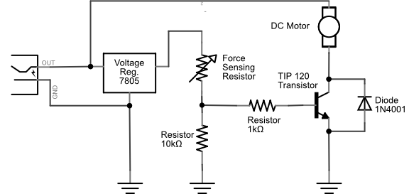
Transistors are often used as electronic switches, to control loads which require high voltage and current from a lower voltage and current. The most common example you’ll see of this in a physical computing class is to use an output pin of a microcontroller to turn on a motor or other high current device. The output pins of a microcontroller can only produce a small amount of current and voltage. But when coupled with a transistor, they can control much more.
Microcontrollers aren’t the only integrated circuits that produce a low voltage and current on their output pins. There are many components that do this. You’ll see a whole range of so-called logic ICs that can’t produce very much current or voltage, but can produce a small change on their output pins that can be read as a data or control signal. The output voltage from devices is often referred to as a logic or a control voltage, as opposed to the supply or load voltage needed to control the high-current device. You can use transistors from circuits like these. For example, you might put a transistor on the output pin of a 555 timer IC (which produces a variable timing pulse), or a shift register IC (which allows you to produce multiple control signals in parallel) to control high current loads from those devices.
Things You’ll Need
Figures 1-12 are the parts you’ll need for this exercise.
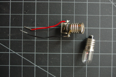
Figure 1. A short solderless breadboard.Figure 2. 22AWG solid core hookup wires. Figure 3. 5-volt voltage regulator, model 7805 Figure 4. Resistors. You’ll need 1-kilohm and 10-kilohm for thisFigure 5. Diodes. Shown here are 1N400x power diodes.Figure 6. DC motorFigure 7. TIP120 Transistor. You can also use a MOSFET, see belowFigure 8. PushbuttonsFigure 9. PotentiometerFigure 10. Force Sensing Resistor (FSR) or other variable resistorFigure 11. DC Power SupplyFigure 12. Small Incandescent lamp bulb or LED bulb and socket
Set Up the Breadboard
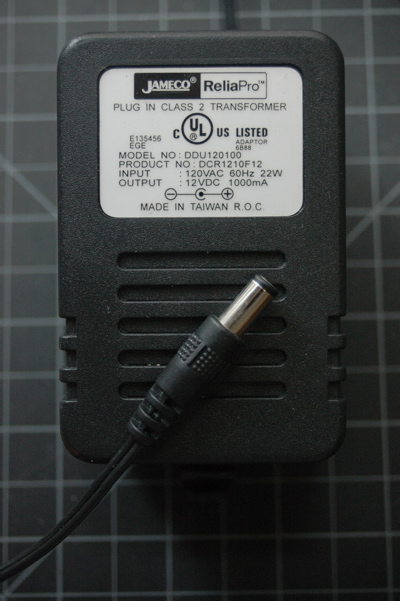
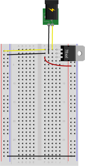
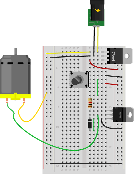
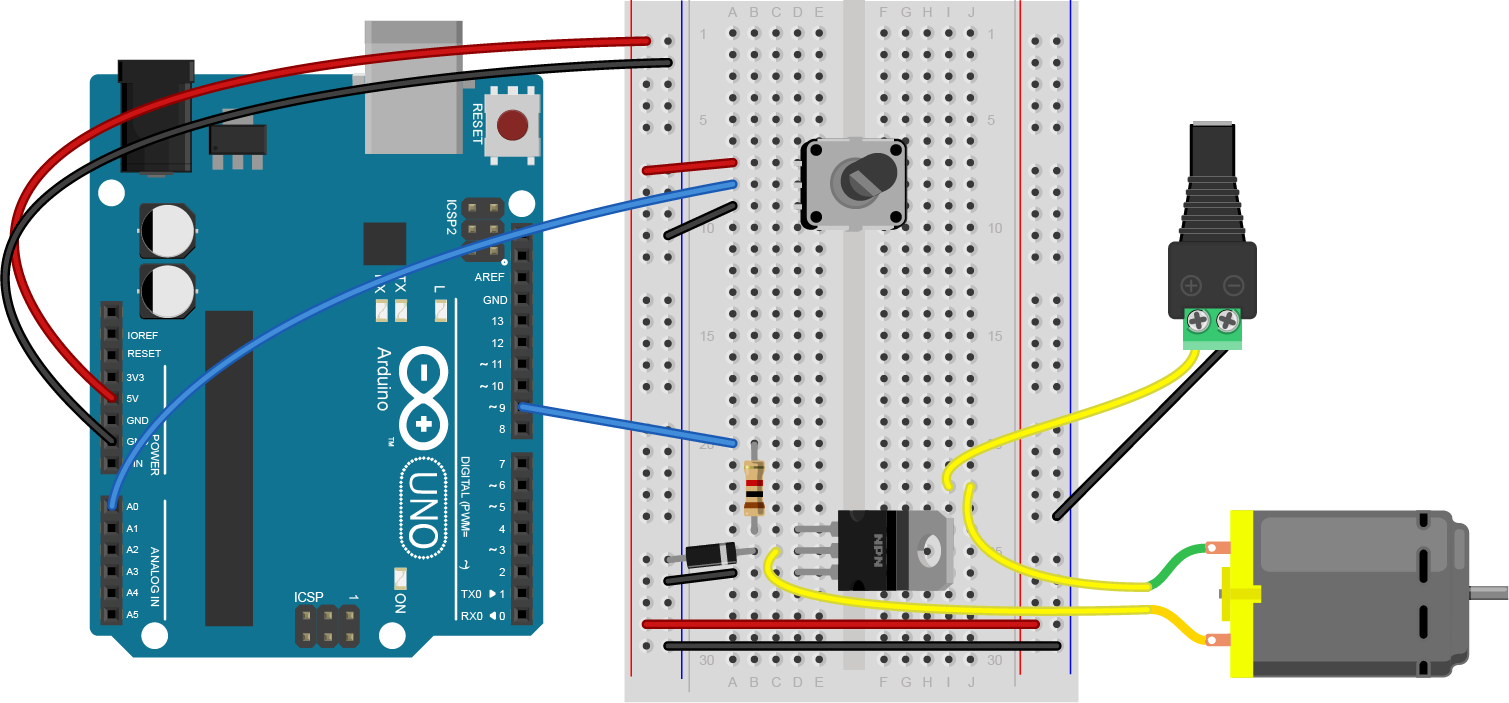
Connect a 7805 5V voltage regulator to your board, and power it from a 9-12V DC power supply. Connect the ground rows on the sides together. Don’t connect the two red rows on the side of the breadboard to each other, though. Wire the breadboard so that the right side of the board receives the 5V output from the regulator, but the left side gets 9-12V directly from your DC power supply. The 5V line is the 5-volt bus or logic supply and the 9-12V line is the high-voltage bus or load supply. The two ground lines are ground. Figure 13 shows the schematic drawing and Figure 14 shows the breadboard view of the circuit explained here.
Figure 14. Schematic drawing of a DC power jack connected to a 7805 5-volt voltage regulator.
Figure 14. DC voltage jack and 7805 voltage regulator on a breadboard. The regulator is supplying 5V and ground holes are supplying voltage to the rest of breadboard.
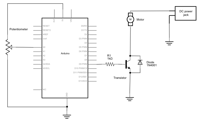
Add a Motor and Transistor
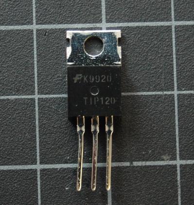
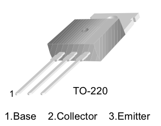
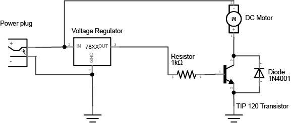
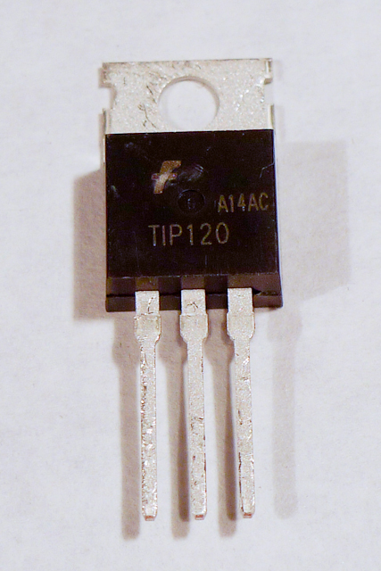
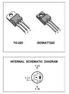
The transistor allows you to control a circuit that’s carrying higher current and voltage from the a lower voltage and current. It acts as an electronic switch. The one you’re using for this lab is an NPN-type transistor called a TIP120. The datasheet for it can be found here. It’s designed for switching high-current loads. It has three connections, the base, the collector, and the emitter as shown in Figure 15 and Figure 16. Attach high-current load (i.e. the motor or light) to its power source, and then to the collector of the transistor. Then connect the emitter of the transistor to ground. Then to control the motor, you apply voltage to the transistor’s base. When there’s at least a 0.7V difference between the base and the emitter, the transistor will “turn on” — in other words, it’ll allow voltage and current to flow from the collector to the emitter. When there’s no voltage difference between the base and the emitter, the transistor turns off, or stops the flow of electricity from collector to emitter.
Figure 15. The schematic symbol of an NPN transistor. B is the base, C is the collector, and E is the emitter.
Figure 16. Pinout drawing of a TIP-120 transistor. From left to right the legs are labelled 1. base, 2. collector, 3. emitter.
Using a MOSFET instead of a TIP120
Figure 17. FQP30N06L MOSFET transistor pin diagram and schematic symbol
You can also use an N-channel MOSFET transistor for this. The diagram and schematic symbols are shown above in Figure 17. The IRF520 and the FQP30N06L MOSFETs are similar in function, and have the same pin configuration as the TIP120, and perform similarly. They can handle more amperage and voltage, but are more sensitive to static electricity damage.
Connect a 1-kilohm resistor from the transistor’s base to another row of the breadboard. This resistor will limit the current to the base.
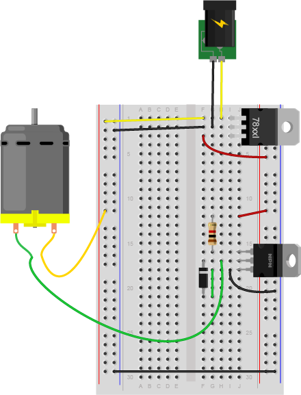
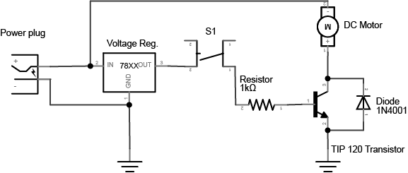
You also need to add a diode in parallel with the collector and emitter of the transistor, pointing away from ground as shown in Figure 18 and Figure 19. The diode to protects the transistor from back voltage generated when the motor shuts off, or if the motor is turned in the reverse direction. This is called a snubber diode, or protection diode. Related topics: Transistors, Relays, and Controlling High-Current Loads
Figure 18. Schematic drawing of a transistor controlling a DC motor.
Figure 19. Breadboard view of a transistor controlling a DC motor.
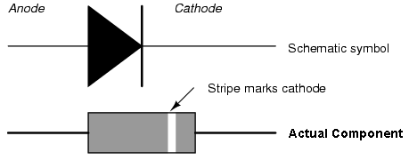
Be sure to add the diode to your circuit correctly. The silver band on the diode denotes the cathode which is the tip of the arrow in the schematic, as shown in Figure 20:
Figure 20. Schematic representation and physical representation of a diode.
This circuit assumes you’re using a 12V motor. If your motor requires a different voltage, make sure to use a power supply that’s appropriate. The TIP120 transistor can handle up to 30V across the collector and emitter, so make sure you’re not exceeding that. Connect the ground of the motor’s supply to the ground of your microcontroller circuit, though, or the circuit won’t work properly.
Add a Switch to Control the Transistor
To turn on the transistor, you need a voltage difference between the base and the emitter of at least 0.7V. Since the emitter is attached to ground, that means any voltage over 0.7V applied to the base will turn the transistor on.
Connect a wire from the 5-volt bus of the board (also called the regulated voltage bus) to the other end of the 1 kilohm resistor as shown above and you should see the motor turn on.
Of course, it’s inconvenient to connect and disconnect a wire like this, so use a switch instead.
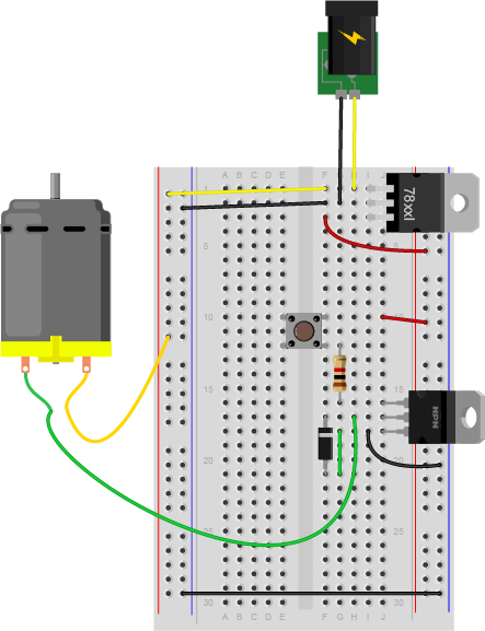
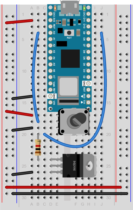
Remove the red wire connecting the resistor to 5 volts and connect one side of a pushbutton or switch to the 5-volt bus, and the other side to the 1K resistor. Figure 21 shows the schematic drawing and Figure 22 shows the breadboard view of the circuit.
Figure 21. Schematic drawing of a transistor controlling a DC motor, with a pushbutton to turn it on and off.
Figure 22. Breadboard drawing of a transistor controlling a DC motor with a pushbutton.
Change the Switch for a Potentiometer
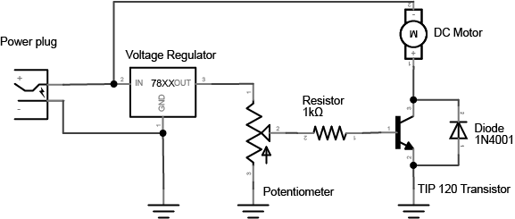
The voltage on the base of the transistor doesn’t have to be controlled by a switch. You can use a potentiometer, connected as a voltage divider, to produce a changing control voltage for the transistor’s base. Figure 23 shows the schematic drawing and Figure 24 shows the breadboard view of the circuit. Related video: Connecting the potentiometer
Figure 23. Schematic drawing of a transistor controlling a DC motor, with a potentiometer to change the speed.
Figure 24. Breadboard drawing of a transistor controlling a DC motor with a potentiometer.
When you turn the potentiometer, you’re producing a varying voltage on the wiper pin. That means you’re changing the voltage on the base of the transistor. Yet the motor doesn’t change its speed. It only turns on or off. When the voltage on the potentiometer’s wiper pin reaches 0.6V, the transistor will turn on. When it’s below 0.6V, the transistor will turn off. The transistor is acting like a switch, not a variable supply. If you want to vary the motor’s speed using a transistor, you need to turn the transistor on and off very fast, and change the ratio of on time to off time. This is called pulse width modulation. You’ll learn more about it in these notes on analog output from a microcontroller and see it in action in the analog lab.
Change the Potentiometer for a Voltage Divider
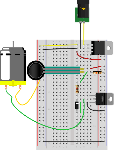
If you’ve understood everything so far and managed to get it to work, here’s where it gets really fun. Imaging you have a variable resistor and you want the motor to turn on when the variable resistor passes a particular threshold. For example, maybe you want to turn on the motor when a temperature changes on a thermistor (temperature sensitive resistor), or when a weight is placed on a force-sensing resistor. To make this happen, change your control circuit to include a variable resistor as shown in Figure 25 and Figure 26.
Figure 25. Schematic drawing of a transistor controlling a DC motor, with a potentiometer to change the speed.
Figure 26. Breadboard drawing of a transistor controlling a DC motor with a voltage divider.
Using a Voltage Divider to Control a Transistor
Extra credit: See if you can work out the correct resistor value for the fixed resistor of the voltage divider that will produce just the right voltage to turn the motor on when you turn on your room’s lights, and off when you turn them off.
Whoa, that blew my mind. How do I do that?
You know you need 0.7V to turn the transistor on, and less than that to turn it off. You know how to measure the resistance of a variable resistor. So find the resistance of your variable resistor with the lights on and with the lights off, and calculate what fixed resistor will give you 0.6V. The input to your voltage divider here is 5V. That means you want 4.3 volts across the variable resistor. You know that the output voltage is proportional to the ratio of the two resistors. And you know that the current running between them is the same, because they are in series. So: Voltage = current * resistance 4.3V = current * photocell resistance therefore, current = 4.3V / variable resistor resistance Then apply this to the fixed resistor: 0.7V = current * fixed resistor resistance therefore, fixed resistor resistance = current / 0.7V or: fixed resistor resistance = (4.3V / variable resistor resistance) / 0.7V
If you’re using a force sensing resistor as your variable resistor (an Interlink model 402 is shown here), you’ll probably find that they’re very sensitive. They tend to be greater than 10 megohms resistance when no force is on them and near zero when pressed. See the graph on page 3 of the datasheet for the voltage output for various fixed resistor values.
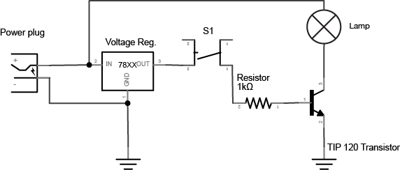
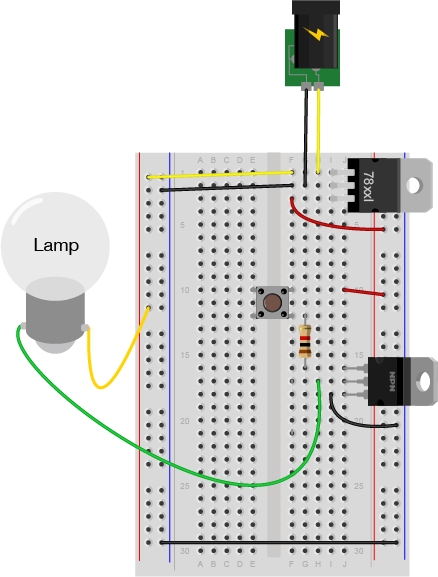
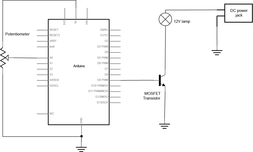
Connect a lamp instead
You could also control a lamp using a transistor. Figure 27 shows the schematic drawing and Figure 28 shows the breadboard view of the circuit. Like the motor, the lamp circuit below assumes a 12V lamp. Change your power supply accordingly if you’re using a different lamp. In the lamp circuit, the protection diode is not needed, since there’s no way for the polarity to get reversed in this circuit:
Figure 27. Schematic drawing of a transistor controlling an incandescent lamp with a pushbutton.
Figure 28. Breadboard drawing of a transistor controlling an incandescent lamp with a pushbutton.
Conclusion
A motor controlled like this can only be turned in one direction. To be able to reverse the direction of the motor, an H-bridge circuit is required. For more on controlling DC motors with H-bridges, see the DC Motor Control lab.
In this tutorial, you’ll learn how to control a DC motor’s direction using a DC Motor Driver.
Introduction
In this tutorial, you’ll learn how to control a DC motor’s direction using a DC Motor Driver.
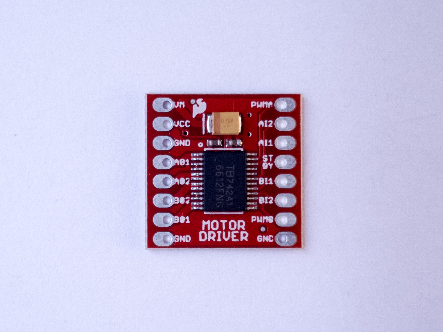
To reverse a DC motor, you need to be able to reverse the direction of the current in the motor. The classic way to do this is using an H-bridge circuit. Though most motor driver chips these days are not in fact H-bridge circuits, the term still persists. This tutorial uses a Toshiba motor driver, the TB6612FNG, which can actually drive two DC motors. Both Sparkfun, Adafruit, and Pololu make breakout boards for the motor driver, though the Sparkfun one is shown in the examples below.
At the end of the lab, an alternative motor driver, the L9110H, is shown. This motor driver can only drive one motor at a time, unlike the TB6612FNG, but it’s more inexpensive than the TB6612FNG.
A solderless breadboard with two rows of holes along each side.
Motor Driver (H-bridge), model TB6612FNG
DC Gearmotor
10-kilohm resistors. These ones are 5-band resistors
Pushbuttons
A DC Power Jack
DC Power Supply
Figures 1-9. The parts you’ll need for this exercise. Click on any image for a larger view.
Prepare the breadboard
Connect power and ground on the breadboard to power and ground from the microcontroller. On the Arduino module, use the 5V or 3.3V (depending on your model) and any of the ground connections, as shown in Figures 10 and 11.
Figure 10. Breadboard drawing of an Arduino Uno on the left connected to a solderless breadboard on the right
Figure 10 shows an Arduino Uno on the left connected to a solderless breadboard, right. The Uno’s 5V output hole is connected to the red column of holes on the far left side of the breadboard. The Uno’s ground hole is connected to the blue column on the left of the board. The red and blue columns on the left of the breadboard are connected to the red and blue columns on the right side of the breadboard with red and black wires, respectively. These columns on the side of a breadboard are commonly called the buses. The red line is the voltage bus, and the black or blue line is the ground bus.
Figure 11. Breadboard view of an Arduino Nano mounted on a solderless breadboard.
As shown in Figure 11, the Nano is mounted at the top of the breadboard, straddling the center divide, with its USB connector facing up. The top pins of the Nano are in row 1 of the breadboard.
The Nano, like all Dual-Inline Package (DIP) modules, has its physical pins numbered in a U shape, from top left to bottom left, to bottom right to top right. The Nano’s 3.3V pin (physical pin 2) is connected to the left side red column of the breadboard. The Nano’s GND pin (physical pin 14) is connected to the left side black column. These columns on the side of a breadboard are commonly called the buses. The red line is the voltage bus, and the black or blue line is the ground bus. The blue columns (ground buses) are connected together at the bottom of the breadboard with a black wire. The red columns (voltage buses) are connected together at the bottom of the breadboard with a red wire.
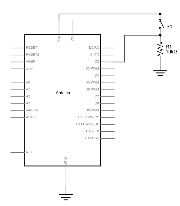
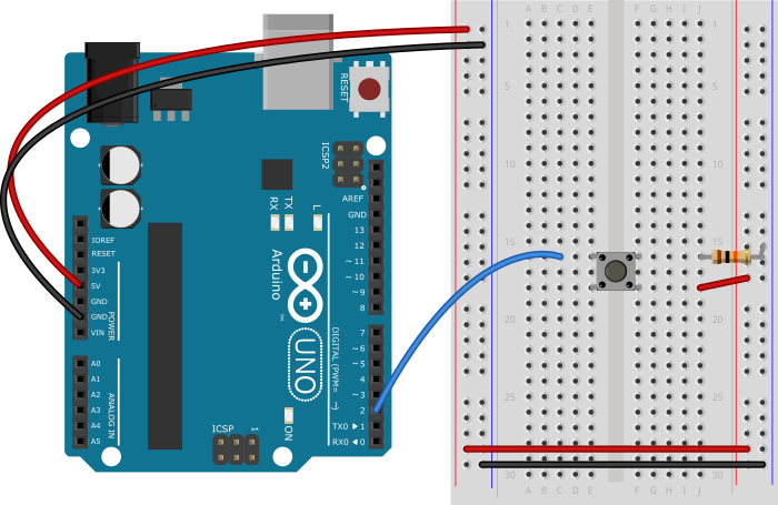
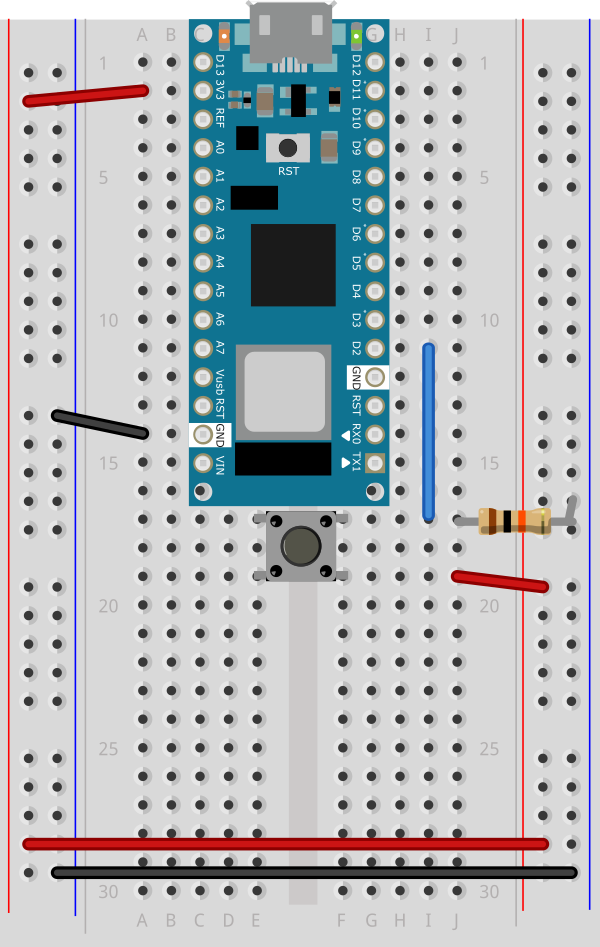
Connect a pushbutton to digital input 2 on the Arduino. Figure 12 shows the schematic, Figure 13 shows the breadboard view for the Uno, and Figure 14 the breadboard view for the Nano.
Figure 12. Schematic Diagram of a pushbutton attached to an Arduino as a digital input. A 10-kilohm resistor connects from the pushbutton to ground.
Figure 13. Breadboard view of a pushbutton attached to an Arduino Uno. The Arduino is connected to a breadboard as described in the image above. A pushbutton is mounted in across the center section of the breadboard. A red wire connects from the left side voltage bus to the lower right pin of the pushbutton. A blue wire connects the upper left pin of the pushbutton to digital pin 2 on the Arduino. A 10-kilohm resistor connects the upper right pin of the pushbutton to the ground bus on the left side of the board.
Figure 14. Breadboard view of a pushbutton attached to an Arduino Nano 33 IoT.
As shown in Figure 14, the Nano is mounted across the center divide of the breadboard with the USB connector pointing up. A pushbutton is mounted in across the center section of the breadboard. A red wire connects from the left side voltage bus to the lower right pin of the pushbutton. A blue wire connects the upper left pin of the pushbutton to digital pin 2 on the Arduino. A 10-kilohm resistor connects the upper right pin of the pushbutton to the ground bus on the left side of the board.
Find a motor
Find yourself a DC motor that runs on low DC voltage within the range of 3 – 15V. This one works well for this, or this one or this one. Discarded toys and printers can be good sources of these also. The ITP free store is almost always a goldmine for discarded motors and fans. Asking classmates and second years is another good approach.
Solder leads to the motor’s terminals. The motor’s direction depends on the polarity, so it’s helpful to use different colors so you know which way the motor will turn when you hook it up.
Optional: Consider testing your motor with a bench power supply from the equipment room. Ask a teacher or resident if you need help setting one up. Begin by adjusting the voltage on the bench power supply and observe its effects. Take note of its speed at different voltages without dipping to low or too high.
Safety Warning: Running a motor at a voltage much lower or much higher than what it’s rated for could potentially damage or permanently destroy your motor. When the motor doesn’t spin, the voltage is too low. When the motor runs hot, or sounds like it’s straining, the voltage is too high.
Powering Your Motor
If your motor can run on 5V (if you’re using an Uno) or 3.3V (if using a Nano 33 IoT ) and less than 500mA, you can use the Arduino’s USB voltage. Most motors require a higher voltage and higher current draw than this, however, so you will need an external power supply. You can use any DC power supply or battery up to 15V with this motor driver as long as your motor can run at that voltage, and as long as the supply can supply as much current as your motor needs. However you choose to power this circuit, make sure the power source is compatible with your motor. For example, don’t use a 9V battery for a 3V motor.
The diagrams below show how to power the motor from an external power supply. To power directly from the Arduino’s Vcc, connect the VMOT pin of the motor driver to the Vcc pin on the Arduino (5V on Uno, 3.3V on Nano)
The TB6612FNG can handle a motor supply voltage up to 15V, and it operates on a logic voltage of 2.7–5.5V. It can control an output current of 1.2A. It has two motor driver circuits, each with two logic inputs and two motor outputs. Each motor driver has a PWM input, because they are expected to be used for speed control for the motor by pulse width modulating this pin. There’s also a Standby pin that you have to connect to voltage through a 10-kilohm pullup resistor to activate the motor driver circuits.
The motor driver has the following pins. The pin numbers shown here are for the Sparkfun breakout board. The order of the pins will be different for the Adafruit and Pololu boards. The Pins are numbered here in a DIP fashion, in a U-shape from top left to bottom left, then bottom right to top right.
VMOT – motor voltage supply input, up to 15V.
Vcc – logic voltage supply input, 2.7-5.5V
Gnd – ground
AO1 – A channel output 1. This is the first motor terminal for the first motor driver
AO2 – A channel output 2. This is the second motor terminal for the first motor driver
BO2 – B channel output 2. This is the second motor terminal for the second motor driver
BO1 – B channel output 1. This is the first motor terminal for the second motor driver
Gnd – ground
Gnd – ground
PWMB – B Channel PWM Enable. This pin controls the speed for channel B, regardless of the channel’s direction
BI2 – B channel input 2. This controls B channel output 2. To control that pin, take this pin HIGH or LOW.
BI1 – B channel input 1. This controls B channel output 1. To control that pin, take this pin HIGH or LOW.
Stdby – enables both drivers when you take it HIGH and disables them when you take it LOW
AI1 – A channel input 1. This controls A channel output 1. To control that pin, take this pin HIGH or LOW.
AI2 – A channel input 2. This controls A channel output 2. To control that pin, take this pin HIGH or LOW.
PWMA – A Channel PWM Enable. This pin controls the speed for channel A, regardless of the channel’s direction
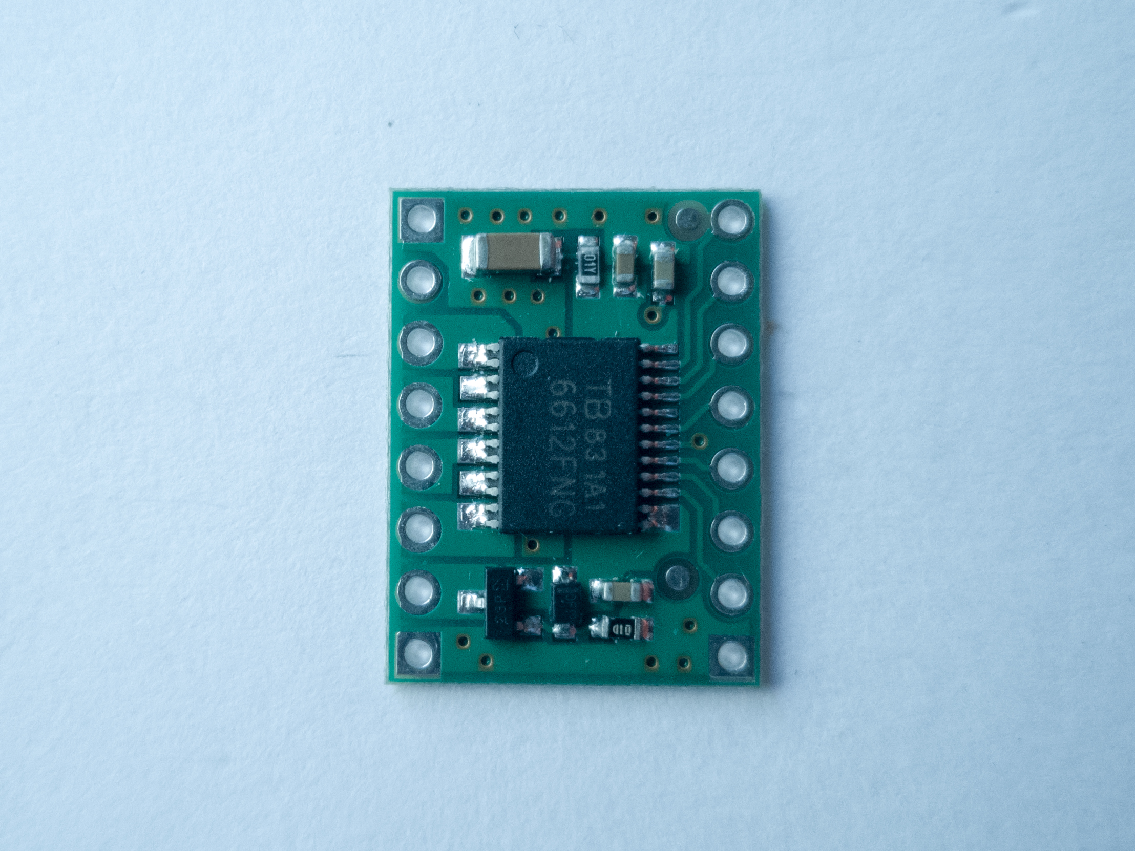
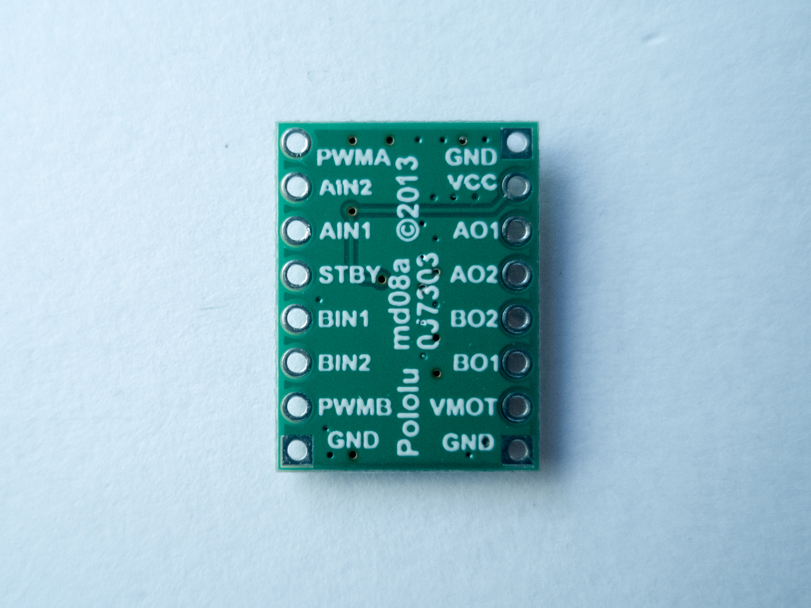
Figure 15 shows the Sparkfun board, and Figures 16 and 17 show the Pololu board front and back. The Pololu board is labeled on the back. You can see that both boards have the same pins, even though the layouts are different.
Figure 15. Motor Driver (H-bridge), model TB6612FNG
Figure 16. Pololu’s TB6612FNG Dual Motor Driver Carrier (front view of the board)
Figure 17. Pololu’s TB6612FNG Dual Motor Driver Carrier (back of the board)
You can change the direction and speed of the motor using the motor driver. The truth table below shows how the motor driver works.
AI1
AI2
PWMA
Effect
H
L
H
Motor turns one direction
L
H
H
Motor turns the other direction
L
L
–
Motor stop
H
H
–
Motor stop
–
–
L
Motor stop
For this lab, the PWMA pin connects to a digital pin on your Arduino so you can send it either HIGH or LOW and turn the motor ON or OFF, or pulse width modulate it to control the speed. The motor logic pins are also connected to designated digital pins on your Arduino so you can set them HIGH and LOW to turn the motor in one direction, or LOW and HIGH to turn it in the other direction. The motor supply voltage connects to the voltage source for the motor, which is usually an external power supply.
Connect the motor to the Driver
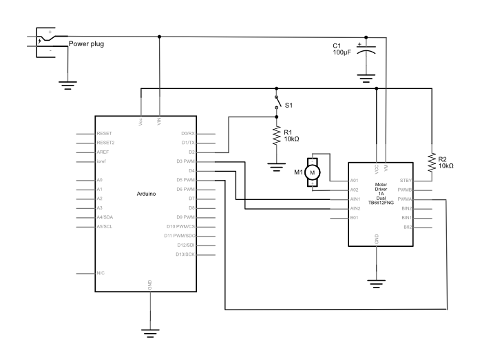
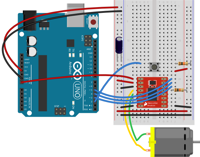
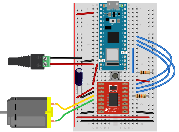
Connect the motor to the driver as shown in Figures 18 – 20. Figure 18 shows the schematic, Figure 19 shows the breadboard view for an Uno, and Figure 20 shows the breadboard view for a Nano.
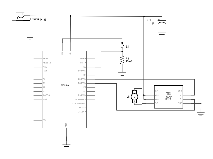
Figure 18. Schematic diagram of an Arduino connected to a motor driver to control a DC motor. The Arduino and switch are connected as described in the drawing above. A motor driver has been added, and is connected as follows: PWMA is connected to the Arduino’s digital pin 5. AIN1 is connected to digital pin 4. AIN2 is connected to digital pin 3 on the Arduino. AO1 and AO2 are connected to the DC motor’s two connections. The ground pins are connected to ground. VMOT is connected to the positive terminal of a DC power source for Arduino and the motor. The power source’s negative terminal is connected to ground. The motor driver’s Vcc pin is connected to the Arduino’s voltage output (5V or 3.3V depending on your model). The Standby pin is connected to voltage through a 10-kilohm resistor. The rest of the driver pins are unconnected.
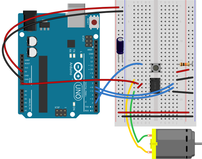
Figure 19. Breadboard drawing of an Arduino connected to a motor driver to control a DC motor. The Arduino and switch are connected as described in the breadboard drawing above. A motor driver has been added, straddling the center of the breadboard. PWMA is connected to the Arduino’s digital pin 5. AIN1 is connected to digital pin 4. AIN2 is connected to digital pin 3 on the Arduino. AO1 and AO2 are connected to the DC motor’s two connections. The ground pins are connected to ground. VMOT is connected to the VIN terminal the Arduino, and the Arduino should be powered through its DC power jack. The power source’s negative terminal is connected to ground. The motor driver’s Vcc pin is connected to the Arduino’s voltage output (5V for the Uno). The Standby pin is connected to voltage through a 10-kilohm resistor. The rest of the driver pins are unconnected. A 100-microfarad capacitor has been added connecting the voltage and ground buses close to the motor driver, to act as a decoupling capacitor.
Figure 20. Breadboard drawing of an Arduino Nano connected to a motor driver to control a DC motor. The Arduino and switch are connected as described in the breadboard drawing above. A DC power jack has been added, connected to the Nano’s ground and Vin pin (pins 14 and 15, respectively). A motor driver has been added, straddling the center of the breadboard. PWMA is connected to the Arduino’s digital pin 5. AIN1 is connected to digital pin 4. AIN2 is connected to digital pin 3 on the Arduino. AO1 and AO2 are connected to the DC motor’s two connections. The ground pins are connected to ground. VMOT is connected to the Nano’s Vin pin, which is connected to the positive terminal of the DC power source for the motor. The power source’s negative terminal is connected to ground. The motor driver’s Vcc pin is connected to the Arduino’s voltage output (3.3V). The Standby pin is connected to voltage through a 10-kilohm resistor. The rest of the driver pins are unconnected. A 100-microfarad capacitor has been added connecting the voltage and ground buses close to the motor driver, to act as a decoupling capacitor.
Note on decoupling capacitors
If you find that your microcontroller is resetting whenever the motor turns on, add a capacitor across power and ground close to the motor. The capacitor will smooth out the voltage dips that occur when the motor turns on. This use of a capacitor is called a decoupling capacitor. Usually a 10 – 100uF capacitor will work. The larger the cap, the more charge it can hold, but the longer it will take to release its charge.
Program the microcontroller
Program the microcontroller to run the motor through the driver. First set up constants for the switch pin, the two motor driver pins, and the PWM enable pin of the motor driver. Use pin 5, one of the pins that can produce a PWM signal using analogWrite(), for the PWM enable pin.
const int switchPin = 2;    // switch input
const int motor1Pin = 3;    // Motor driver leg 1 (pin 3, AIN1)
const int motor2Pin = 4;    // Motor driver leg 2 (pin 4, AIN2)
const int pwmPin = 5;       // Motor driver PWM pin
In the setup(), set all the pins for the motor driver as outputs, and the pin for the switch as an input. Then set the PWM enable pin high so the driver can turn the motor on.
void setup() {
    // set the switch as an input:
    pinMode(switchPin, INPUT);

    // set all the other pins you're using as outputs:
    pinMode(motor1Pin, OUTPUT);
    pinMode(motor2Pin, OUTPUT);
    pinMode(pwmPin, OUTPUT);

    // set PWM enable pin high so that motor can turn on:
    digitalWrite(pwmPin, HIGH);
  }
In the main loop() read the switch. If it’s high, turn the motor one way by taking one motor driver pin high and the other low. If the switch is low, reverse the direction by reversing the states of the two pins.
void loop() {
    // if the switch is high, motor will turn on one direction:
    if (digitalRead(switchPin) == HIGH) {
      digitalWrite(motor1Pin, LOW);   // set leg 1 of the motor driver low
      digitalWrite(motor2Pin, HIGH);  // set leg 2 of the motor driver high
    }
    // if the switch is low, motor will turn in the other direction:
    else {
      digitalWrite(motor1Pin, HIGH);  // set leg 1 of the motor driver high
      digitalWrite(motor2Pin, LOW);   // set leg 2 of the motor driver low
    }
  }
Once you’ve seen this code working, try modifying the speed of the motor using the analogWrite() function, as explained in the Analog Lab. Use analogWrite() on the PWM enable pin of the motor, and see what happens as you change the value of the analogWrite().
An Alternative Motor Driver
If you don’t have a TB6612FNG motor driver, or if you want something simpler and less expensive, the L9110H driver will also control a DC motor’s direction and speed. It can handle and input voltage of 2.5V-12V at 800mA of current. It can drive only one motor, unlike the TB6612FNG, and it can’t control stepper motors like that driver can. But it is inexpensive.
THe L9110H comes in an 8-pin DIP package. There are two inputs, labeled the A and B channels, and they are connected to two outputs, also labeled A and B. Your motor connects to the outputs and your control pins connect to the inputs. Vcc connects to the motor supply and GND connects to ground. Its pins, numbered from top left in a U shape as usual, are as follows:
OA – output for the A channel
Vcc – motor supply voltage
Vcc – motor supply voltage
OB output for the B channel
GND – ground
IA – input for the A channel
IB – input for the B channel
GND – ground
Figure 21 shows the schematic, and Figures 22 and 23 show it connected to an Uno and a Nano 33 IoT, respectively.
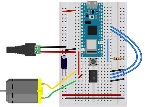
Figure 21. Schematic view of an L9110H H-bridge motor driver connected to an Arduino. A pushbutton is connected to pin 2 of the Arduino as shown in the circuits above. An external DC power supply is connected to the Arduino and the motor as shown in the circuits above as well, along with a 100-microfarad decoupling capacitor. A DC motor is connected to pins OA and OB of the H-bridge. Pins Vcc are both connected to the DC power supply and pins GND are connected to ground. Pin IA is connected to pin 5 of the Arduino, and pin IB is connected to pin 6 of the Arduino. Figure 22. Breadboard view of an L9110H H-bridge motor driver connected to an Arduino Uno. A pushbutton is connected to pin 2 of the Arduino as shown in the circuits above. The L9110H straddles the center divide of the breadboard with pins 1 and 8 facing the top of the diagram. The Arduino should be powered through its DC power jack. The Vin pin of the Arduino connects to the L9110H’s Vcc pins (physical pins 2 and 3). The motor is connected to the L9110H’s OA and OB pins (physical pins 1 and 4). A 100-microfarad decoupling capacitor is connected to the voltage and ground buses on the breadboard. Pins GND (physical pins 5 and 8) are connected to ground. Pin IA (physical pin 6) is connected to pin 5 of the Arduino, and pin IB (physical pin 6) is connected to pin 6 of the Arduino.Figure 23. Breadboard drawing of an Arduino Nano connected to a L9110H H-bridge motor driver to control a DC motor. The Arduino and switch are connected as described in the breadboard drawing above. A DC power jack has been added, connected to the Nano’s ground and Vin pin (pins 14 and 15, respectively). The L9110H straddles the center divide of the breadboard with pins 1 and 8 facing the top of the diagram. The Vin pin of the Arduino connects to the L9110H’s Vcc pins (physical pins 2 and 3). The motor is connected to the L9110H’s OA and OB pins (physical pins 1 and 4). A 100-microfarad decoupling capacitor is connected to the voltage and ground buses on the breadboard. THe L9110H’s ins GND (physical pins 5 and 8) are connected to ground. Pin IA (physical pin 6) is connected to pin 5 of the Nano, and pin IB (physical pin 6) is connected to pin 6 of the Nano.
To control the motor, you take one input high and the other low, just like with the previous motor driver. Since this driver has no PWM pin, you have to pulsewidth modulate the high input to manage speed control, though.
The program below controls the L9110H, setting the speed to about half the maximum whenever you push the button. To make a variable speed you could add a potentiometer and change the value of the speed variable using the potentiometer.
const int switchPin = 2;  // pushbutton input
const int motor1Pin = 5;  // H-bridge leg 1 (pin 6, 1A)
const int motor2Pin = 6;  // H-bridge leg 2 (pin 7, 2A)

// speed of the motor (0-255):
int speed = 127;

void setup() {
  // set the pushbutton as an input:
  pinMode(switchPin, INPUT);

  // set all the other pins you're using as outputs:
  pinMode(motor1Pin, OUTPUT);
  pinMode(motor2Pin, OUTPUT);
}

void loop() {
  // if the pushbutton is high, motor will turn on one direction:
  if (digitalRead(switchPin) == HIGH) {
    // set leg 1 of the H-bridge low:
    digitalWrite(motor1Pin, LOW);
    // set leg 2 of the H-bridge high:
    analogWrite(motor2Pin, speed);
  }
  // if the pushbutton is low, motor will turn in the other direction:
  else {
    // set leg 1 of the H-bridge high:
    digitalWrite(motor1Pin, speed);
    // set leg 2 of the H-bridge low:
    digitalWrite(motor2Pin, LOW);
  }
}
Get creative
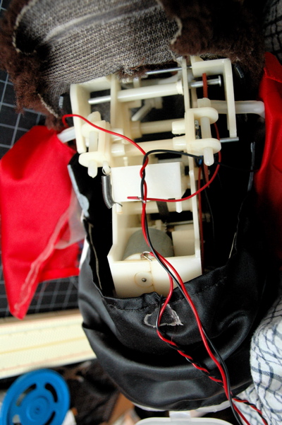
Motors can be used to make things move, vibrate, rise, fall, roll, creep, or whatever you can think of, in response to user input from a digital input device (switch, floor sensor, tripwire, etc). Look inside moving toys, you’ll find a number of excellent motors and gears you can re-purpose. See the innards of a cymbal monkey below as an example. Perhaps you can re-design the user interface to a toy, using the microcontroller to mediate between new sensors on the toy and the motors of the toy.
If you used a motor in this lab, consider any toys you have that have a motor you could take control over. Charley Chimp™ has a motor that’s easy to control from an Arduino, for example.
Figure 21. The guts of a Charley Chimp™ cymbal-playing monkey.
In this tutorial, you’ll learn how to control a high-current DC load such as a DC motor or an incandescent light from a microcontroller.
Introduction
In this tutorial, you’ll learn how to control a high-current DC load such as a DC motor or an incandescent light from a microcontroller. Microcontrollers can only output a very small amount of current from their output pins. These pins are meant to send control signals, not to act as power supplies. The most common way to control another direct current device from a microcontroller is to use a transistor. Transistors allow you to control the flow of a high-current circuit from a low-current source.
Safety Warning: This tutorial shows you how to control high-current loads. This comes with a higher danger of injury from electricity than the earlier tutorials. Please be careful and double-check your wiring before plugging anything in, and never change your wiring while your circuit is powered.
Things You’ll Need
Arduino Nano 33 IoTFlexible jumper wires. These wires are quick for breadboard prototyping, but can get messy when you have lots of them on a board.A solderless breadboard with two rows of holes along each side. The . board is turned sideways so that the side rows are on top and bottom in this view. There are no components mounted on the board. Gearmotor. Any DC motor in the 3-15V DC range will work in with this circuit, though 4-6V is an ideal range.A DC Power JackDC Power Supply to match your motor. If your motor is a 4-6V motor, you should use a 4-6V DC power supply.Small Incandescent lamp bulb and socket. You could use low-voltage DC LED lamps as well.Diodes. Shown here are 1N400x power diodes.PotentiometerTIP120 transistorFigures 1-10. The parts you’ll need for this exercise. Click on any image for a larger view.
Prepare the breadboard
Connect power and ground on the breadboard to power and ground from the microcontroller. On the Arduino module, use the 5V or 3.3V (depending on your model) and any of the ground connections, as shown in Figures 11 and 12.
Figure 11. Breadboard drawing of an Arduino Uno on the left connected to a solderless breadboard on the right
Figure 11 shows an Arduino Uno on the left connected to a solderless breadboard, right. The Uno’s 5V output hole is connected to the red column of holes on the far left side of the breadboard. The Uno’s ground hole is connected to the blue column on the left of the board. The red and blue columns on the left of the breadboard are connected to the red and blue columns on the right side of the breadboard with red and black wires, respectively. These columns on the side of a breadboard are commonly called the buses. The red line is the voltage bus, and the black or blue line is the ground bus.
Figure 12. Breadboard view of an Arduino Nano mounted on a solderless breadboard.
As shown in Figure 12, the Nano is mounted at the top of the breadboard, straddling the center divide, with its USB connector facing up. The top pins of the Nano are in row 1 of the breadboard.
The Nano, like all Dual-Inline Package (DIP) modules, has its physical pins numbered in a U shape, from top left to bottom left, to bottom right to top right. The Nano’s 3.3V pin (physical pin 2) is connected to the left side red column of the breadboard. The Nano’s GND pin (physical pin 14) is connected to the left side black column. These columns on the side of a breadboard are commonly called the buses. The red line is the voltage bus, and the black or blue line is the ground bus. The blue columns (ground buses) are connected together at the bottom of the breadboard with a black wire. The red columns (voltage buses) are connected together at the bottom of the breadboard with a red wire.
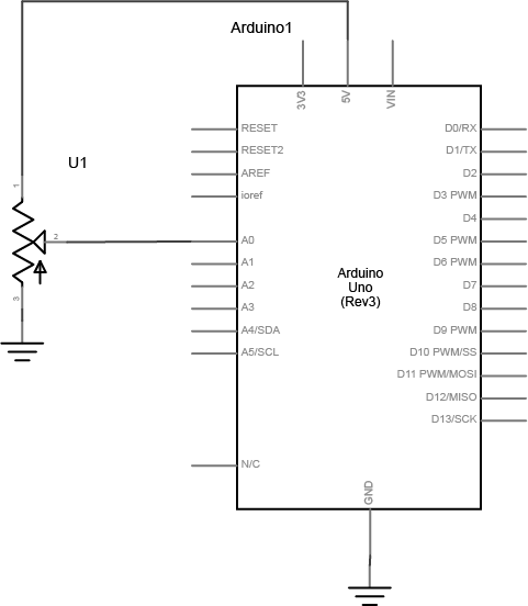
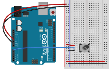
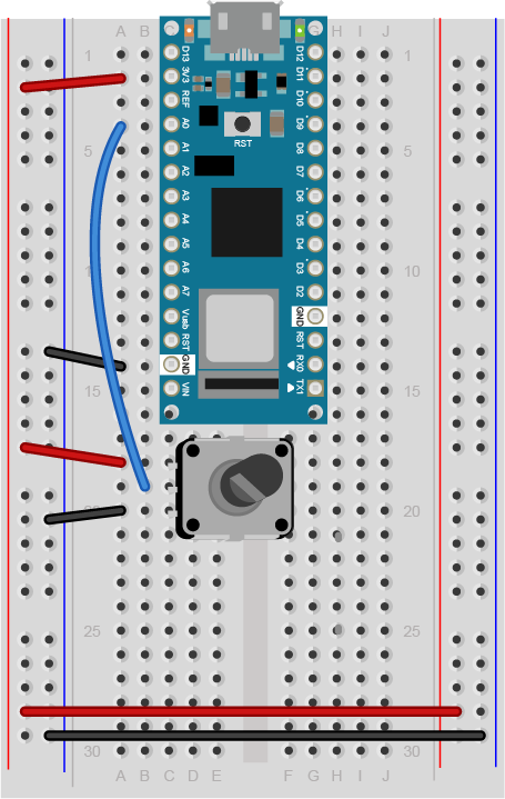
Connect a potentiometer to analog in pin 0 of the module as shown in Figure 13 through Figure 15:
Figure 13. Schematic view of a potentiometer connected to analog in 0 of the Arduino
Figure 14. Breadboard view of a potentiometer connected to analog in 0 of an Arduino Uno. The potentiometer is mounted in three rows of the left center section of the breadboard. The two outside pins of the potentiometer are connected to the voltage and ground bus rows, respectively. The center pin is connected to analog in 0 of the Uno.
Figure 15. Breadboard view of a potentiometer connected to analog in 0 of an Arduino Nano. The potentiometer is mounted in three rows of the left center section of the breadboard below the Nano. The two outside pins of the potentiometer are connected to the voltage and ground bus rows, respectively. The center pin is connected to analog in 0 (physical pin 4) of the Nano.
Connect a Transistor to the Microcontroller
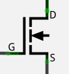
The transistor allows you to control a circuit that’s carrying higher current and voltage from the microcontroller. It acts as an electronic switch. You can use a bipolar Darlington transistor like the TIP120, or you can use a MOSFET like the IRF520 or FQP30N06L for this lab. All three will work the same way and use the same circuit. See Figures 16 through Figure 19 for the drawings and schematic symbols of the transistors.
Figure 16. Pinout drawing of a TIP-120 transistor. From left to right the legs are labelled 1. base, 2. collector, 3. emitter.Figure 17. The schematic symbol of an NPN transistor. B is the base, C is the collector, and E is the emitter.Figure 18. NPN Transistor and N-Channel MOSFET side by side with a schematic diagram of the MOSFET. G is the gate (equivalent of base), D is the drain (collector) and S is the source (emitter).Figure 19. Schematic symbol of an N-channel MOSFET, where G is the gate (equivalent of base), D is the drain (collector) and S is the source (emitter).
The IRF520 MOSFET has the same pin configuration as the TIP120, and performs similarly with a 5V gate voltage. The FQP30N06L MOSFET has the same pin configuration, and operates on as low as 1.0V, and works well for 3.3V applications. MOSFETs can generally handle more amperage and voltage, and switch a little faster (the difference is in microseconds, so you won’t notice), but they are more sensitive to static electricity damage. They are grouped into N-Channel and P-Channel, which are equivalent to NPN and PNP bipolar transistors.
All three transistors mentioned here are designed for switching high-current loads. All of them have built-in protection diodes. Each has three connections Table 1 below details their connections.
Bipolar Transistor
MOSFET
Connection
Base
Gate
Connects to microcontroller output
Collector
Drain
Connects to power through load
Emitter
Source
Connects to ground
Table 1. Names of the pins on the bipolar transistor and the equivalent names on the MOSFETs
The datasheets for each of the recommended transistors can be found below:
Here’s the main operating principle of using a transistor as a switch: When a small voltage and current is applied between the base (or gate) and the emitter (or source), the transistor allows a larger current to flow between the collector (or drain) and emitter (or source).
Figures 20 through 22 show how to connect the transistor’s input to the microcontroller’s output. Note that this circuit isn’t complete, because the transistor isn’t controlling anything yet.
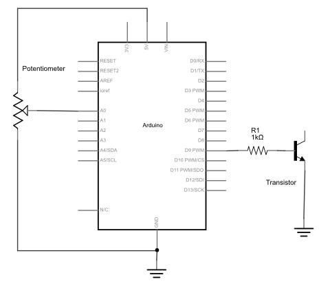
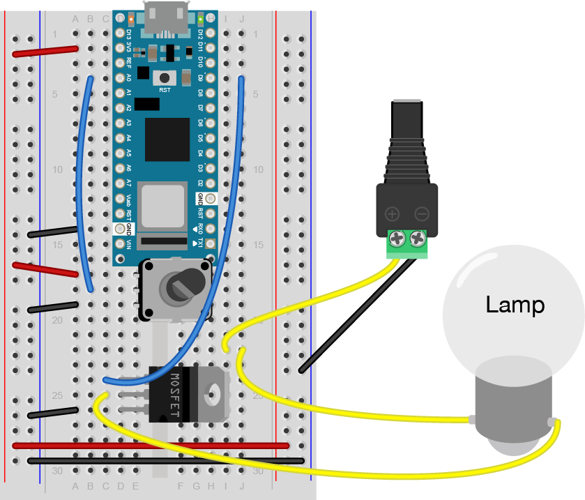
Figure 20. Schematic view of a potentiometer and transistor connected to an Arduino. First leg of the potentiometer is connected to +5 volts. The second leg connected to analog in 0 of the Arduino. The third leg is connected to ground. The base (or gate) of the transistor is connected to digital pin 9 of the Arduino through a 1-kilohm resistor. The emitter (or source) is connected to ground.
Figure 21. Breadboard view of a potentiometer and transistor connected to an Arduino. First leg of the potentiometer is connected to +5 volts. The second leg connected to analog in 0 of the Arduino. The third leg is connected to ground. The base (or gate) of the transistor is connected to digital pin 9 of the Arduino through a 1-kilohm resistor. The emitter (or drain) is connected to ground.
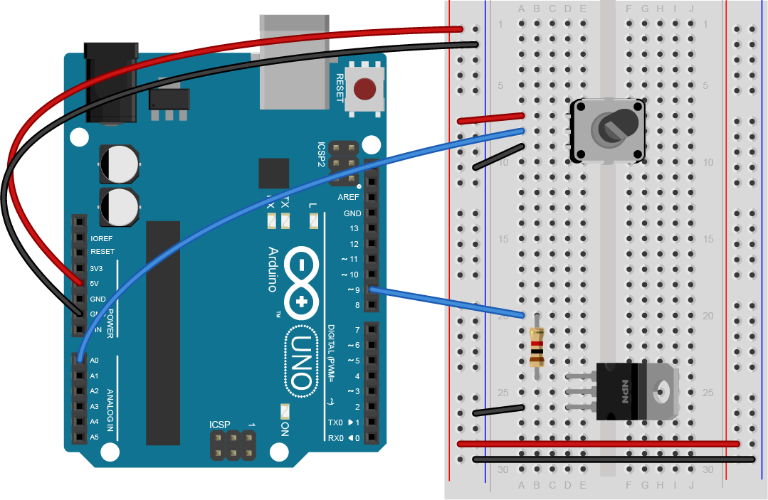
Figure 22. Breadboard view of a potentiometer and transistor connected to an Arduino Nano. First leg of the potentiometer is connected to +3.3 volts. The second leg connected to analog in 0 of the Arduino. The third leg is connected to ground. The base (or gate) of the transistor is connected to digital pin 9 of the Arduino through a 1-kilohm resistor. The emitter (or drain) is connected to ground.
Connect a Motor and Power Supply
Attach a DC motor to the collector (or drain) of the transistor as shown in Figures 23 through 25. Most motors will require more current than the microcontroller can supply, so you will need to add a separate power supply as well. If your motor runs on around 9V, you could use a 9V battery. A 5V motor might run on 4 AA batteries (6V). You could also use a 12-volt DC wall adapter and a 5-volt regulator. A 12V battery may need a 12V DC wall adapter, or a 12V battery. The ground of the motor power supply should connect to the ground of the microcontroller on the breadboard.
Add a 1N4001 power diode in parallel with the collector and emitter of the transistor, pointing away from ground. The diode protects the transistor from back voltage generated when the motor shuts off, or if the motor is turned in the reverse direction. Used this way, the diode is called a protection diode or a snubber diode. You can omit the diode if you don’t have one, as the transistors recommended here all have a built-in protection diode
Figure 23. Schematic view of a potentiometer connected to analog in 0 of the Arduino. A transistor is connected to Digital Pin 9. A DC motor connects to the transistor and a DC jack. The DC jack connects its positive wire to the first wire of the DC motor. The negative wire of the DC jack connects to ground. The second wire of the DC motor connects to the collector (or drain) of the transistor. A 1N400x diode’s anode is connected to the collector (or drain), and its anode is connected to ground.
Figure 24. Breadboard view of an Arduino connected to a potentiometer, a transistor, a DC motor, and a DC jack. A transistor is connected to Digital Pin 9. A DC motor connects to the transistor and a DC jack. The DC jack connects its positive wire to the first wire of the DC motor. The negative wire of the DC jack connects to ground. The second wire of the DC motor connects to the collector (or drain) of the transistor. A 1N400x diode’s anode is connected to the collector (or drain), and its anode is connected to ground.
Figure 25. Breadboard view of an Arduino Nano connected to a potentiometer, a transistor, a DC motor, and a DC jack. A transistor is connected to Digital Pin 9 through a 1-kilohm resistor. A DC motor connects to the transistor and a DC jack. The DC jack connects its positive wire to the first wire of the DC motor. The negative wire of the DC jack connects to ground. The second wire of the DC motor connects to the collector (or drain) of the transistor. A 1N400x diode’s anode is connected to the collector (or drain), and its anode is connected to ground.
Be sure to add the diode to your circuit correctly. The silver band on the diode denotes the cathode which is the tip of the arrow in the schematic, like so in Figure 26:
Figure 26. Schematic representation and physical representation of a diode. The silver band on the diode indicates the anode end.
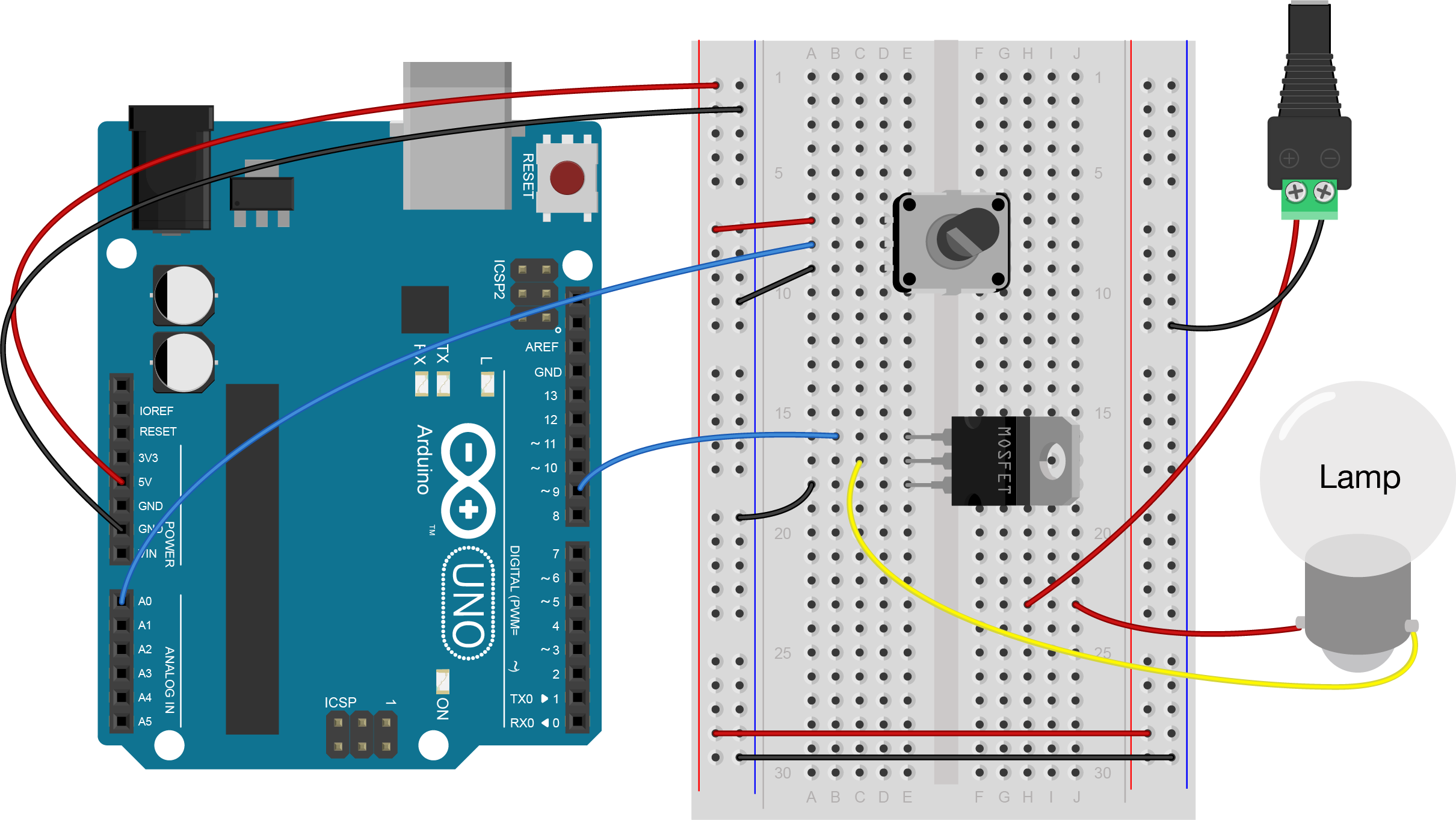
Connect a Lamp Instead of a Motor
You could also attach a lamp using a transistor. There are many 12V incandescent lamps, designed for use in track lighting, gallery lighting, and so forth. Nowadays, there are many 12V DC LED equivalents of the 12V AC lamps as well. Here are a few examples:
The lamp circuit in Figures 27 through 29 assumes a 12V lamp. MOSFETs are generally best for switching incandescent and LED lamps, so the circuit below uses a MOSFET. In the lamp circuit, the protection diode is not needed, since there’s no way for the polarity to get reversed in this circuit.
Figure 27. Schematic view of a potentiometer, MOSFET, and lamp connected to an Arduino. The gate of a MOSFET transistor is connected to Digital Pin 9 of the Arduino. A 12V lamp connects to the drain of the transistor and a DC jack. The DC jack connects its positive wire to the first wire of the lamp. The negative wire of the DC jack connects to ground. The second wire of the lamp connects to the drain of the transistor. The source of the transistor connects to ground.
Figure 28. Breadboard view of a potentiometer, MOSFET, and lamp connected to an Arduino. The gate of a MOSFET transistor is connected to Digital Pin 9 of the Arduino. A 12V lamp connects to the drain of the transistor and a DC jack. The DC jack connects its positive wire to the first wire of the lamp. The negative wire of the DC jack connects to ground. The second wire of the lamp connects to the drain of the transistor. The source of the transistor connects to ground.
Figure 29. Breadboard view of a potentiometer, MOSFET, and lamp connected to an Nano. The gate of a MOSFET transistor is connected to Digital Pin 9 of the Nano. A 12V lamp connects to the drain of the transistor and a DC jack. The DC jack connects its positive wire to the first wire of the lamp. The negative wire of the DC jack connects to ground. The second wire of the lamp connects to the drain of the transistor. The source of the transistor connects to ground.
Program the microcontroller
Write a program to test the circuit, whether it’s a motor or a lamp. Your program should make the transistor pin an output in the setup method. Then in the loop, it should turn the motor on and off every second, just like the blink sketch does.
const int transistorPin = 9;    // connected to the base of the transistor

 void setup() {
   // set  the transistor pin as output:
   pinMode(transistorPin, OUTPUT);
 }

 void loop() {
   digitalWrite(transistorPin, HIGH);
   delay(1000);
   digitalWrite(transistorPin, LOW);
   delay(1000);
 }
Now that you see it working, try changing the speed of the motor or the intensity of the lamp using the potentiometer.
To do that, read the voltage of the potentiometer using analogRead(). Then map the result to a range from 0 to 255 and save it in a new variable. Use that variable to set the speed of the motor or the brightness of the lamp using analogWrite().
const int transistorPin = 9;    // connected to the base of the transistor

 void setup() {
   // set  the transistor pin as output:
   pinMode(transistorPin, OUTPUT);
 }

 void loop() {
   // read the potentiometer:
   int sensorValue = analogRead(A0);
   // map the sensor value to a range from 0 - 255:
   int outputValue = map(sensorValue, 0, 1023, 0, 255);
   // use that to control the transistor:
   analogWrite(transistorPin, outputValue);
 }
For the motor users: A motor controlled like this can only be turned in one direction. To be able to reverse the direction of the motor, an H-bridge circuit is required. For more on controlling DC motors with H-bridges, see the DC Motor Control lab.
Come Up with an Application
Now that you’ve got motor or lamp control, come up with an application.
If you used a motor in this lab, consider any toys you have that have a motor you could take control over. Charley Chimp™ has a motor that’s easy to control from an Arduino, for example.
The guts of a Charley Chimp™ cymbal-playing monkey.
You’ve got the beginnings of a good desk lamp or table lamp, if you chose to use a light bulb in this lab. How will you control it? How will you mount the switchor the dimmer knob? You might also want to consider a gooseneck pipe to mount your socket on, and a socket that goes with it. Here are a few inspirations:
In this tutorial you’ll learn the basics of soldering for electronics.
In this tutorial you’ll learn the basics of soldering for electronics.
Introduction
If you’re going to do any electronics work, you’re going to have to do some soldering, or have someone help you do it. Many people fear it before they’ve done it, but it’s really pretty simple to do. This exercise will show you how to solder a DC Power connector to a set of wires for a breadboard.
In order to get the most out of this tutorial, you should have a basic understanding of electrical circuits, so you understand why you’re soldering, and you should know what a solderless breadboard is.
Soldering is a process in which you use a metal alloy with a low melting point to fuse together two other pieces of metal. It’s used in electronics all the time, because it ensures a mechanically solid connection between two materials that’s also electrically conductive. To do this, you heat the alloy, called solder, until it melts, and let it run across the two metal pieces you’re attempting to join.
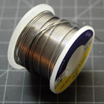
There are many different ways to solder, but the most common for hobbyists uses a handheld soldering iron and a reel of solder wire. That’s the process that’s demonstrated here.
In the steps that follow, you’ll connect jumper wires to a power connector. When you’re prototyping a circuit, you need all of your parts to have connections that can fit firmly in a solderless breadboard. Many electronic components and connectors don’t have such connections, so you need to solder them on. The DC power jack shown in this exercise is one such connector. It comes with no wires, just connections onto which you’re expected to solder your own wires. You’ll solder wires onto it, and then you’ll solder a pair of stiff header pins onto the ends of the wires.
Preparing the parts
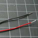
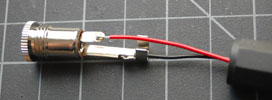
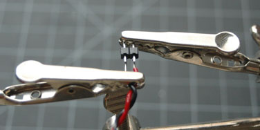
Cut a red and a black wire about four inches (10cm) in length. Strip the ends back about 1/4 of an inch (1/2 cm). Bend a hook on one end of each wire. Unscrew the power jack. As shown in Figure 9, connect the red wire to the hole in the the center tab of the power, and the black to the hole in the outside tab. Use pliers to crimp the hooked wires to their connections on the jack. If the connections aren’t soldered, you’ll get an inconsistent connection at best, and a short circuit at worst.
Heat up your soldering iron. It doesn’t need to be cranked to its maximum heat. For most small jobs like this, 600-700 degrees Fahrenheit (315-370 C) will work just fine. You really only need the iron hot enough to heat the metal connections so that they’ll melt the solder.
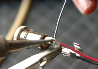
The best solder joints are those where the two metal connections to be joined are heated up together, and the solder is then melted by the heat of the connections. That way, all three metals cool down together. As they cool, they contract. You want them to contract together, so there is no cracking of the joint between them.
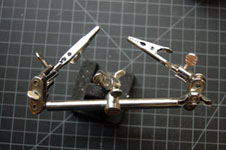
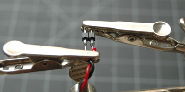
Make sure the two pieces of metal are touching each other firmly. Use a helping hand or a clamp to hold them in place. When they’re solidly touching, and held firmly by your clamp or helping hands, touch the iron to the joint between the wire and the metal to heat the joint (see Figure 10). Then touch the solder to the joint (NOT to the iron) until it melts. This should make a clean solder with a small blob of solder.
You may find that it takes longer to heat the connection in order for the solder to melt. The larger a connector is, the more time it takes to heat. This is because the metal of the connector is conducting the heat away from the joint. If your connector is too big, you may need to use a mechanical joint, as opposed to a solder joint. The DC power jacks shown in this tutorial will solder just fine, however.
As the solder cools down, its surface will go from shiny to a more matte surface. When it cools down, test the joint by wiggling it to make sure it’s firm.
Repeat the process with the other wire and the other part of the connector.
Figure 10. Preparing the solder joint. The solder should be touched to the joint, not to the iron.
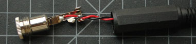
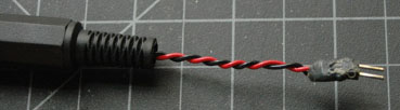
Twist the wires together and thread them through the sleeve of the jack.
The result should look like this in Figure 11:
Figure 11. The inside of a soldered power connector, with red and black wires twisted together.
Soldering the Header Pins
The two wires are now properly separated inside the connector, but the other ends can move freely. Even though these two ends can fit firmly in a breadboard, it can be dangerous to leave them loose. They might touch each other while you have the connector plugged in, causing a short circuit.
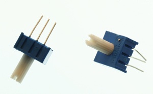
Header pins(Figure 12) are a great way to maintain the spacing between wires that you need to fit into a breadboard. If you solder two of them to the ends of your wires, with the metal spacer still on them, they’ll keep your wire leads safely apart.
Figure 12. Breakaway header pins
Trim the ends of the wires to the same length, and strip them back to about 1/8th of an inch. Break off two header pins and hold them in one clip of a helping hands device. Clip the wires in the other clip, and align them with the header pins like so in Figure 13:
Figure 13. Header pins ready to be soldered to the ends of your wires.
Solder the wires to the headers. Move quickly, as the plastic spacer between the headers can melt (that’s another reason not to heat your iron too hot). When you’re done soldering, you should have two separate blobs like this in Figure 14:
Figure 14. Header pins successfully soldered to wires.
If you can’t see space between the two solder joints, de-solder them and do it again. You need to be sure there’s no connection between these wires that can cause a short circuit, and the best way to do that is to leave space.
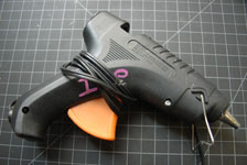
Take a hot glue gun and surround the bare connections to insulate them and provide some strain relief. When you’re done, you should have a connection like this in Figure 15:
Figure 15. DC power connector assembled, with the wire-to-header connections insulated with hot glue.
Make sure you can tell which pin is connected to the red wire and which is connected to the black.
Testing
Before you connect it to power, take a meter and check the connections for continuity. The center pin should be connected to the red wire, and the outer rim should be connected to black. When that’s good, you’re ready to use it.
What Else Can I Solder?
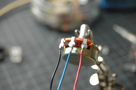
Any time you have loose mechanical connections, you should solder them if you can. For example, many common potentiometers have ring contacts(Figure 16). If you loop the wires around the rings as shown in Figure 17, you get inconsistent readings from your potentiometer. Solder the leads if they are loose.
Figure 16. A potentiometer with ring contacts, ready for soldering.
Figure 17. Potentiometer with wires successfully soldered.
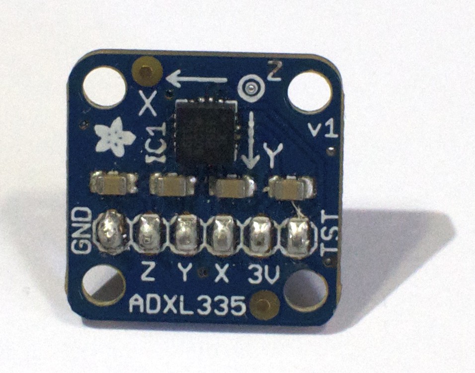
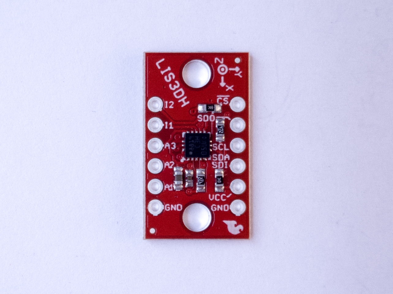
Many breadboard-friendly printed circuit boards come without headers soldered on. One of the most common mistakes beginners make with these boards is to push them into a breadboard using headers, but with no solder. This will also give inconsistent readings. Figure 18 shows an ADXL335 accelerometer module pins are properly soldered.
Figure 18. An ADXL335 accelerometer module. There are six pins along the bottom, labeled GND, Z, Y, X, 3V, and ST (left to right). These pins are properly soldered (You can find this accelerometer on adafruit.com)
When in doubt, if you have loose connections, solder them!
This is an introduction to basic digital input and output on a microcontroller. In order to get the most out of it, you should know something about the following concepts. You can check how to do so in the links below:
When you’re trying to sense activity in the physical world using a microcontroller, the simplest activities you can sense are those in which you only need to know one thing about the physical world: Whether something is true or false. Is the viewer in the room or out? Are they touching the table or not? Is the door open or closed? In these cases, you can determine what you need to know using a digital input, or switch.
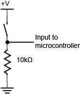
Digital or binary inputs to microcontrollers have two states: off and on. If voltage is flowing, the circuit is on. If it’s not flowing, the circuit is off. To make a digital circuit, you need a circuit, and a movable conductor which can either complete the circuit, or not.
Figure 1. Schematic of a Digital Input to a microcontroller
Figure 1 shows the electrical schematic for a digital input to a microcontroller. The current has two directions it can go to ground: through the resistor or through the microcontroller. When the switch is closed, the current will follow the path of least resistance, to the microcontroller pin, and the microcontroller can then read the voltage. The microcontroller pin will then read as high voltage or HIGH. When the switch is open, the resistor connects the digital input to ground, so that it reads as zero voltage, or LOW.
On an Arduino module, you declare the pin to be an input at the top of your program. Then you read it for the values 1 (HIGH) or 0 (LOW), like so:
void setup() {
 // declare pin 2 to be an input:
 pinMode(2, INPUT);
 declare pin 3 to be an output:
 pinMode(3, OUTPUT);
}

void loop() {
 // read pin 2:
 if (digitalRead(2) == 1) {
   // if pin 2 is HIGH, set pin 3 HIGH:
   digitalWrite(3, HIGH);
 } else {
   // if pin 2 is LOW, set pin 3 LOW:
   digitalWrite(3, LOW);
}
Digital output
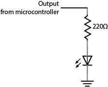
Just as digital inputs allow you to sense activities which have two states, digital or binary outputs allow you to control activities which can have two states. With a digital output you can either turn something off or on. Figure 2 is the schematic diagram for digital output controlling an LED:
Figure 2. Schematic of and led as a digital output from a microcontroller
On an Arduino module, you declare the pin an output at the top of the program just like you did with inputs. Then in the body of the program you use the digitalWrite() command with the values HIGH and LOW to set the pin high or low, as you’ve seen above. Here’s a simple blinking LED program in Arduino:
As inputs, the pins of a microcontroller can accept very little current. Likewise, as outputs, they produce very little current. The electrical signals that they read and write are mainly changes in voltage, not current. When you want to read an electrical change that’s high-current, you limit the current input using a resistor. Similarly, when you want to control a high-current circuit, you use a transistor or relay, both of which allow you to control a circuit with only small voltage changes and minimal current. Related video: Transistor
In this lab you will learn about some of the components you’ll use frequently when making electronic circuits.
Introduction
In this lab you will learn about some of the components you’ll use frequently when making electronic circuits. For more on any given component, please check out its datasheet. There are no specific activities in this lab other than to examine the components and to familiarize yourself with them.
A datasheet or spec sheet is a document (printed or .pdf) that describes the technical characteristics of a sensor, electronic component, product, material or other. It includes details on how to use the component in a circuit and other useful design info on how to integrate it into a system together with specifications on performance and other characteristics that are important to know.
You’ll hear a few different terms for the parts you’re working with. A component is an electrical part that has a particular function, as described below. A component’s package refers to its physical form. The package is not dependent on what the actual part is. You’ll see a few components below that have the same package, like some of the voltage regulators and some of the transistors.
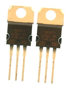
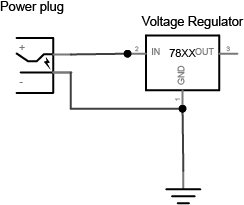
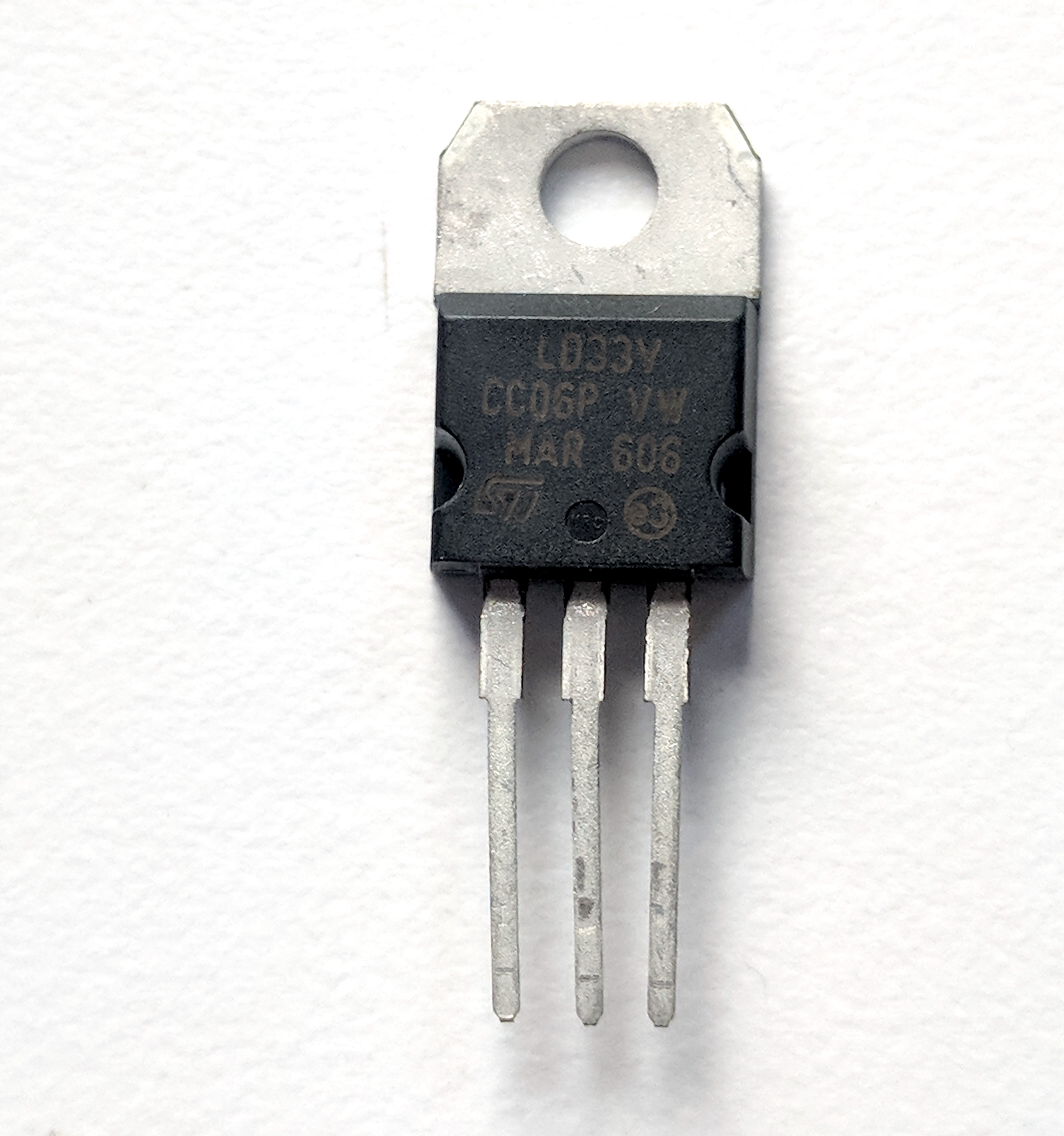
Different electronic circuits operate at different voltages. For example, the Arduino Uno operates at 5 volts, while the Arduino Nano 33 IoT and BLE, and the MKR series, operate at 3.3 volts. A voltage regulator takes a range of DC voltage as input and convert it to a constant voltage. For example, this regulator shown in Figure 1, a 7805 regulator, takes a range of 9 – 15 volts DC input and converts it to a constant 5-volt output. Using this regulator, you could power a 5-volt motor or a string of addressable LEDs from a 12-volt power source.
Note the label on the regulator that reads “7805”. This is the part number. Other parts have the same physical package, however. This is a TO-220 package. Many different parts use this same package, for example, and not all of them are voltage regulators. Also, sometimes the same part will come in different packages, so you can use it in different size devices.
The 7800 series regulators come in many different voltages. 7805 is a 5-volt regulator. 7809 is a 9-volt regulator. 7812 is a 12-volt regulator. All the regulators of this family have the same pin connections. In the image above, the left leg is connected to the input voltage. The middle leg is connected to ground. The right leg is the output voltage.
3.3V regulators are also common. Note that not all regulators which share the same package have the same pin configuration. For example, the LD1117V33, a 3.3V regulator shown in Figure 2, comes in the same physical package as a 7805, but its pins are in a different order. The LD1117V33’s pins, from left to right, are ground, output voltage, input voltage.
LED
Figure 3. LEDs. Shown here are four LEDs. The one on the right is an RGB LED. You can tell this because it has four legs, while the others have only two legs.
LEDs, or Light Emitting Diodes (see Figure 3), are diodes that emit light when given the correct voltage and current. Like all diodes, they are polarized, meaning that they only operate when oriented correctly in the circuit. The anode of the LED connects to voltage, and the cathode connects to ground. The anode in the LEDs in this photo is the longer leg on each LED. LEDs come in many different packages. The packages above have built-in lenses.
These LEDs are the cheapest you can buy, and they’re not very bright. You can get super-bright LEDs as well, which are much brighter. If you’re working on applications that need very small light sources, you can also get LEDs in a surface mount package.
LEDs can only handle a limited amount of current and voltage. The details should be covered in each LED’s datasheet. Here is the datasheet of a typical white LED. You’ll see that the forward current is 30 mA max, and the forward voltage is between 2.9 and 3.6V. That means if you give it 30mA at 3.6V, you should get maximum brightness out of it. If you don’t have the datasheet for your LED, here’s a link to a handy LED current calculator. Try putting in the supply voltage (3.3V or 5V), the voltage drop across the LED (the forward voltage), and the current (30 mA) and see what value of resistance you get. For most common LEDs running at 3.3 or 5 volts, a resistor about 220 will limit the current safely while still providing enough to light the LED.
Solderless breadboards are reusable prototyping tools for electronics that allow you to build and experiment with circuits simply by plugging components in and out of its rows and columns. They come in different shape and sizes. Figure 4 shows a typical short solderless breadboard. It has two rows of holes on either side of the board, usually used as voltage and ground buses. The board is turned in this photo so that the bus rows are on top and bottom. In the center of the board, there are thirty rows of holes. There is a divider down the center of the board that breaks up the rows of holes into separate rows. There are five holes per row on the center left and on the center right of each row.
Resistors
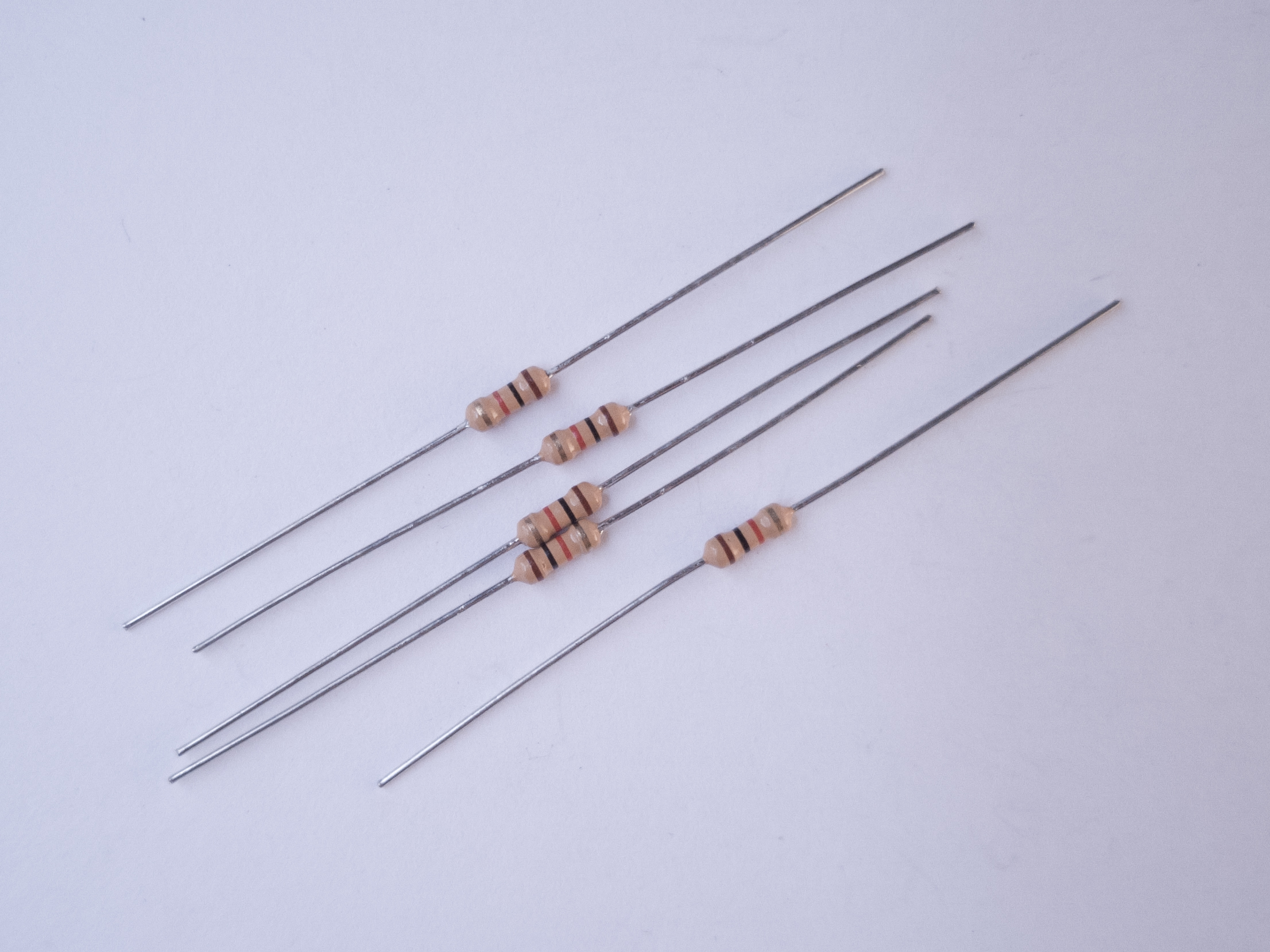
Figure 5. Resistors. Shown here are 220-ohm resistors. You can tell this because they have two red and one brown band, followed by a gold band.
Resistors resist the flow of electrical current. When placed in series, they reduce the voltage, and limit the current. The bands on a resistor indicate the resistor’s value. Here’s a handy resistor color code calculator. Resistors come in 4-band, 5-band, and 6-band models. In a 4-band resistor, the bands represent the first digit, second digit, multiplier, and tolerance. The resistors shown in Figure 5 are 4-band resistors marked red, red, brown, and gold, for 2, 2, times 101, 5%. In other words, these are 220 ohm resistors, +/-5%. The resistor color code calculator explains the bands for 5-and 6-band resistors as well.
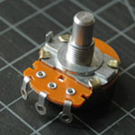
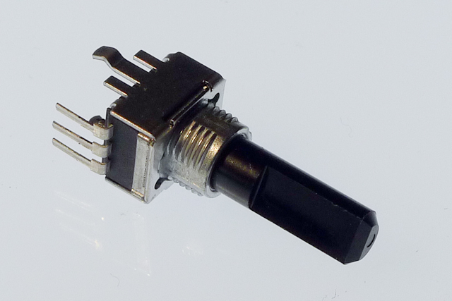
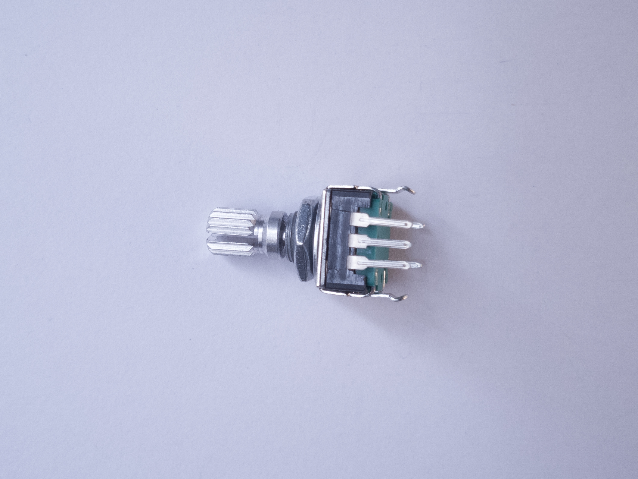
Potentiometers
Figure 6. Potentiometer. The one shown here has three legs spaced 0.1 inches apart and can be therefore mounted on a solderless breadboard.
Potentiometers are variable resistors. The two outside terminals act as a fixed resistor. A movable contact called the wiper moves across the resistor, producing a variable resistance between the center terminal and either of the two sides. The potentiometer in Figure 6 has pins so you can mount it on a breadboard.
Trimmer potentiometers like those shown in Figure 7 are designed to be mounted on a circuit board, and are difficult to turn, so you can use them to adjust a circuit. They’re very small. They’re handy to use as physical variables, to tune your project.
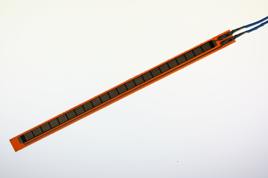
Force Sensing Resistors
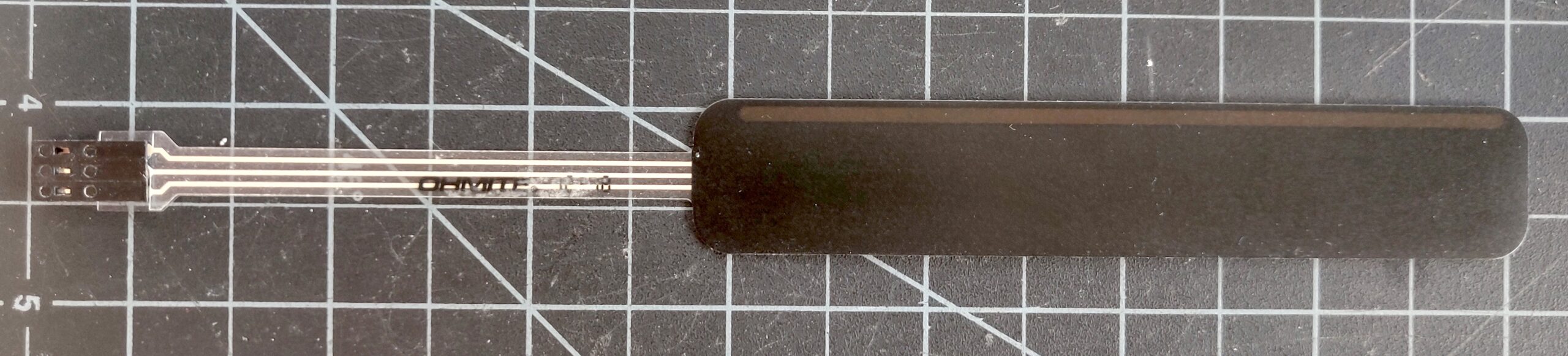
Force sensing resistors are sensors that change their resistance in response to force. They’re usually used to make analog alternatives alternatives to buttons. They’re made of a substrate of resistive rubber between two layers of conductive ink on a plastic film. They come in a variety of form factors. Figure 8 shows a pair of force sensors about 2.5cm across, sized for finger presses. There are a few companies who make them, including Interlink, Ohmite, and Tekscan.
Figure 8. Force sensing resistors
Flex Sensors (Flex Resistors)
Flex sensors are similar to force sensing resistors in construction, but they change their resistance as they bend. They are typically about the length of a finger, and they work well for measuring the bend of a finger. Spectrasymbol make these.
Figure 9. Flex sensor
Force Sensing Potentiometers
Force Sensing Potentiometers, sometimes called SoftPots, are also similar to force sensing resistors. The difference is that a force sensing resistor gives one value wherever you press on it, while a force sensing potentiometer acts like a normal potentiometer: the value changes depending on where along its length you press. They come in linear and round form factors. Ohmite, Interlink, and Spectrasymbol make FSPs.
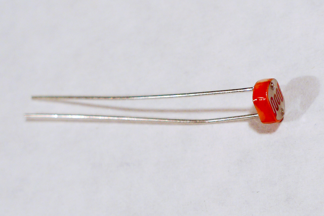
Light-dependent resistors, or photocells, are variable resistors whose resistance changes with the intensity of the light falling on the resistor. Photocells, as seen in Figure 11, are made with cadmium sulfide, which is a toxic chemical. Increasingly, they are being replaced in hobbyist kits by phototransistors, which are somewhat less toxic (see below).
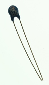
Thermistors
Figure 12. Themistor, or temperature-sensitive resistor
Thermistors, seen in Figure 12, are variable resistors whose resistance changes as the temperature changes. You measure the resistance between the two legs of the thermistor and expose the top to a varying temperature in order to vary the resistance between the two legs.
Switches
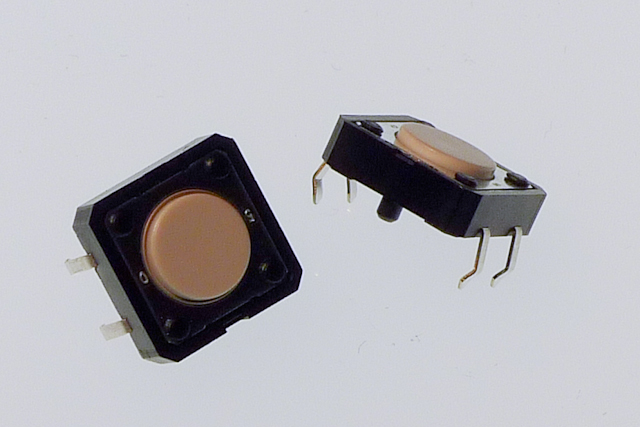
Figure 13. Pushbuttons, also called momentary switches
Switches are one form of digital input. There are many kinds of switches. The two most useful categories are momentary switches, which remain closed only when you press them, and toggle switches, which stay in place after you switch them.
Pushbuttons are a common type of momentary switch. The pushbuttons in the photo in Figure 13 above are designed to be mounted on a circuit board. They are very small, less than 1 centimeter on a side. They have four pins. When the button is facing you, top two are connected to each other, and the bottom two are connected to each other. Pushing the button connects the top pins to the bottom pins.
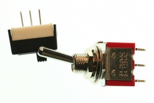
Toggle switches (Figure 14) stay in one position when you flip them. Wall light switches are common examples of toggle switches. Unlike a momentary switch, a toggle switch can be used to turn a device on or off, because they stay in one state when you remove your hand. The toggle switches below each have three connectors, also called pins or legs. They’re usually labeled C for common, NO for Normally Open, and NC for Normally Closed. When you switch the switch, it will open the connection between the common pin and the normally closed pin, and close the connection between the common pin and the normally open pin. Switch it the other way, and you will reverse the connection.
Figure 14. Toggle switches
Rotary Encoder
Figure 15. Rotary encoder
A rotary encoder is a sensor that usually looks a bit like a potentiometer. It has a central shaft that you can turn with your fingers, or with an axle. It produces a pair of electrical pulses as you turn the shaft of the encoder, one slightly before or after the other, depending on the direction you are turning the shaft. Unlike a potentiometer, they can turn endlessly. They are used both as tangible controls, when you want a knob that turns endlessly, and as rotary sensors for motors and axles. The encoder in Figure 15 has three pins. The center is connected to ground, and the two side pins produce the pulses. The Encoder library for Arduino is useful for reading these.
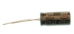
Capacitors store electrical energy while there’s energy coming in, and release it when the incoming energy stops. They have a variety of uses. One common use is to smooth out the dips and spikes in an electrical supply. This use is called decoupling.
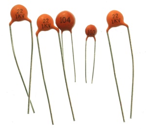
Ceramic capacitors are unpolarized. They generally have very small capacitance values. They’re useful decoupling caps in a low-current circuit. You often see them used to decouple the power going into a microcontroller or other integrated circuit.
The number on a ceramic cap gives you its value and order of magnitude. For example, 104 on the capactors in Figure 16 indicates a 0.1 microfarad (uF) cap. 103 indicates a 0.01 microfarad cap.
Figure 17. Electrolytic capacitor
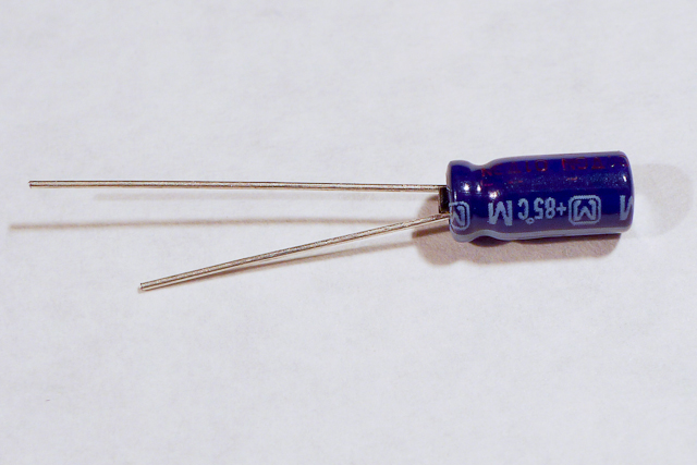
Electrolytic capacitors (Figure 17) can generally store more charge than ceramic caps, and are longer lasting. They’re usually polarized, meaning that they have a positive leg and a negative leg. This is because current flows more efficiently through them one way than the other.
Figure 18. Electrolytic capacitor, showing the minus sign on the negative side.
An electrolytic cap will have a + or – on one side, as shown in Figure 18.
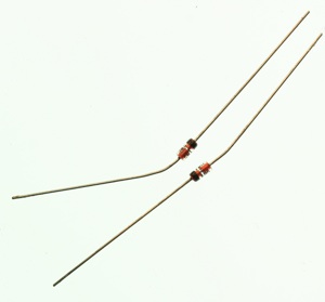
Diodes
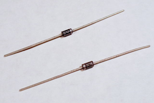
Figure 19. Diodes. Shown here are 1N400x power diodes. The body of the component is black, and the end is silver. The silver end indicates the cathode end of the diode.
Diodes permit voltage to flow in one direction and block it in the other direction. LEDs are a type of diode, as are the 1N4001 diodes shown in Figure 19. They’re useful for stopping voltage from going somewhere you don’t want it to go. The 1N4001 diodes are power diodes, capable of carrying a higher amount of current than other diodes.
Figure 20. Zener Diodes
Zener diodes (Figure 20) have a breakdown voltage past which they allow current to flow in both directions. They’re used to chop off excess voltage from a part of a circuit. They are usually smaller than power diodes.
Transistors act as electronic switches. When you put a small voltage across the base and emitter, the transistor allows a larger current and voltage to flow from the collector to the emitter. The transistor shown above in Figure 21, a TIP120, is a type of transistor known as a Darlington transistor. It is usually used to control high-current loads like motors. Note that it uses the same physical form factor, or package, as the voltage regulator above (the TO-220 package).
The TIP120 shown here is jus one option for controlling high current loads. Metal Oxide Semiconductor Field Effect Transistors, or MOSFETS, are also good for controlling motors, lights, and other high current loads. These two models also come in the same physical package as the TIP120. The IRF510 and IRF520 MOSFETs have the same pin configuration as the TIP120, and perform similarly with a 5V gate voltage. The FQP30N06L MOSFET has the same pin configuration, and operates on as low as 1.0V, and works well for 3.3V applications. MOSFETs can generally handle more amperage and voltage, but are more sensitive to static electricity damage.
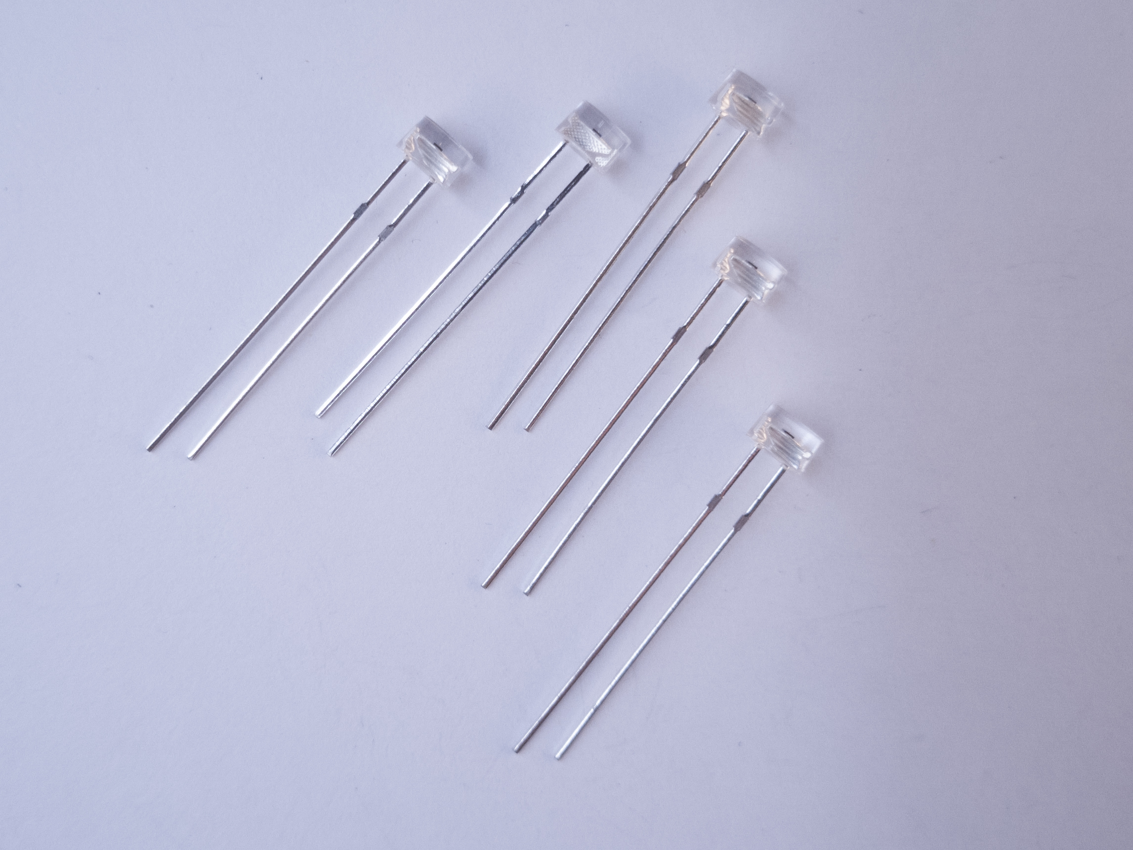
Figure 15. Phototransistors. The short leg goes to voltage, and the long leg goes to the input pin of a microcontroller.
Phototransistors are transistors, but instead of being controlled by electricity, they are controlled by light. The base of a phototransistor is photosensitive. They often look like LEDs. The ones in Figure 15, Everlight model ALS-PT243-3C/L177, have flat tops to differentiate them from LEDs. The short leg of a phototransistor is the emitter, and the long leg is the collector. The lens is the base. To use them in an analog input circuit. emitter goes to voltage and the collector goes to your input pin. A 10-kilohm pulldown resistor connects the input pin to ground, just as it would if you were using a photocell..
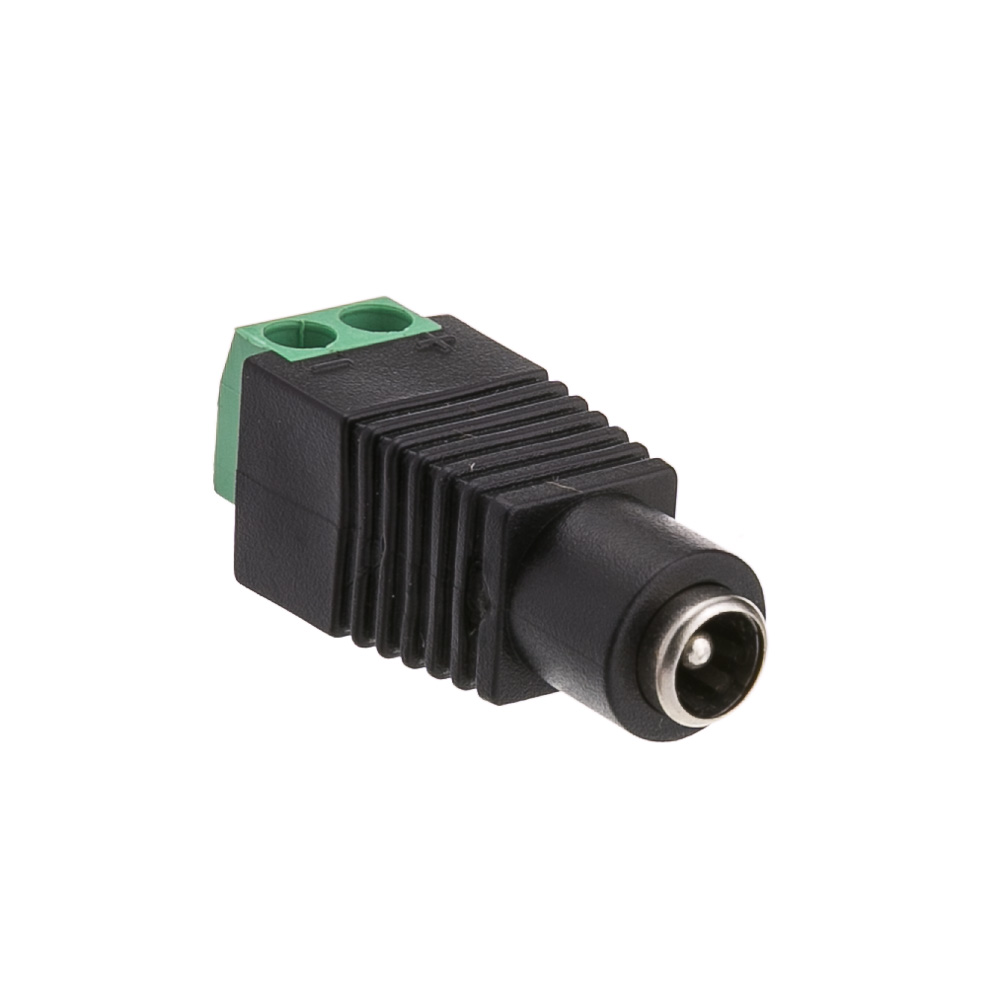
Power Jacks
Figure 22. A DC Power Jack
DC Power jacks are used to connect your breadboard to a DC power supply that you can plug into a wall. They’re less common in microcontroller circuits now that USB power connectors and USB wall plugs are common, but they are still very handy when you have only a DC power supply to work with. The one in Figure 22 has screw terminals on the back to which you can connect wires to connect to your breadboard. It is a 2.1mm inside diameter, 5.5mm outside diameter jack, which is a very common size.
Battery Holders
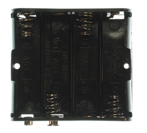
Figure 23. AA battery holder
Figure 24. 9V battery snap with DC power plug on it.
Battery connectors like the ones shown in Figures 23 and 24 are good for connecting batteries to your project. The one in Figure 20 can hold 4 AA batteries, and has a 9V battery snap on the outside. The one in Figure 21 has a DC power jack on one end, and a 9V battery snap on the other end.
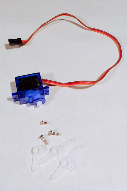
A servo motor is a motor paired with an encoder (e.g. a potentiometer) to provide position/speed readings and control messages in a feedback loop. This loop is used to precisely control of the servo’s degree of rotation. RC servomotors like the one shown in Figure 25 can only turn 180 degrees. They are often used for the rudder control on remote control planes and cars. The plastic bits shown in the photo are called horns, and they attach to the shaft to let you attach the motor to the mechanism that you want to control.
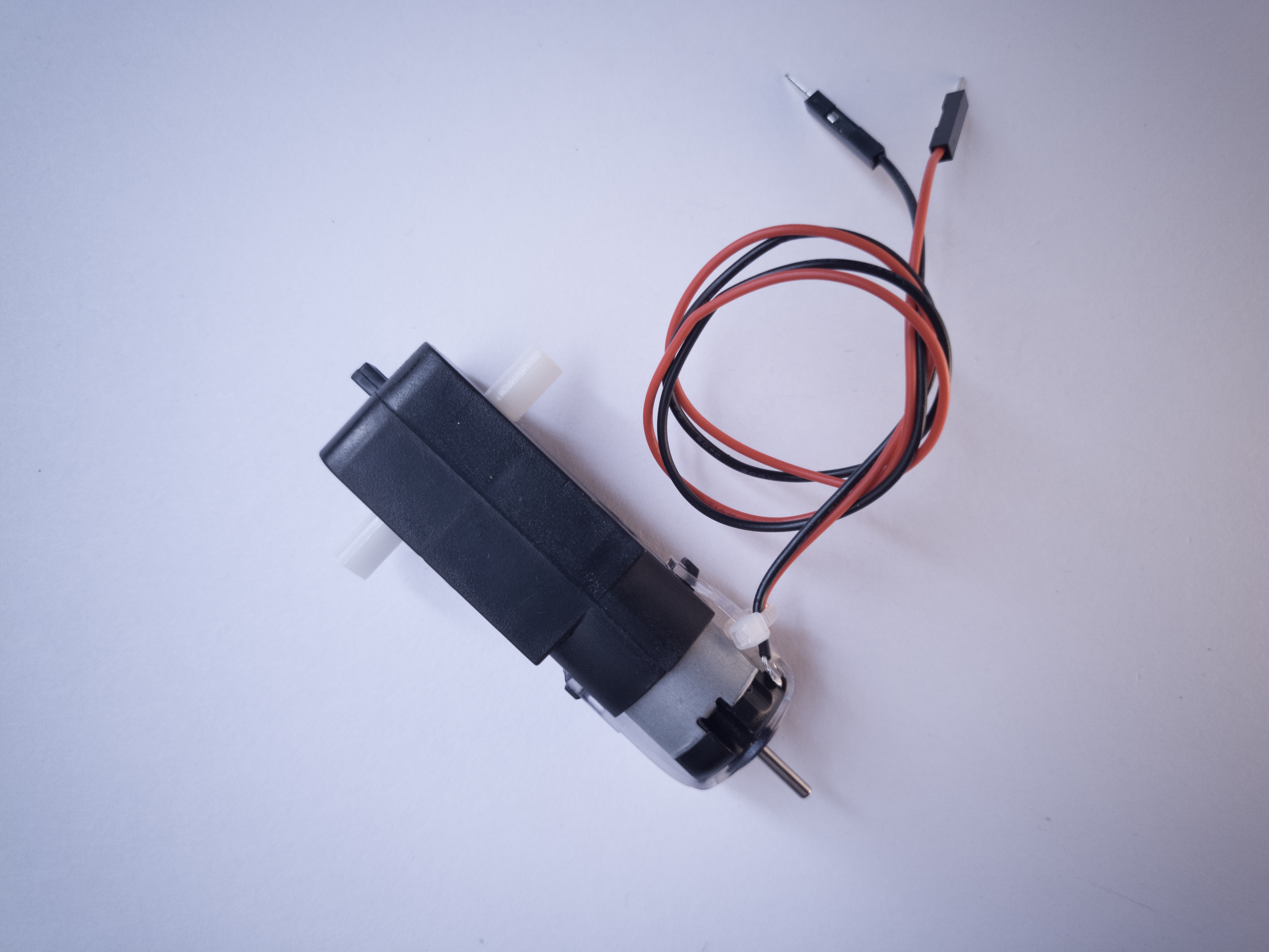
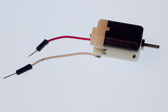
DC motors, as seen in Figure 26, utilize induction (an electromagnetic field generated by current flowing through a wire coil) to rotate a central shaft. You can reverse the direction that the shaft rotates by reversing the leads powering it.
Motor Driver
Figure 27. Motor Driver (H-bridge), model TB6612FNG
A motor driver, sometimes called an H bridge, is an electronic circuit that enables a voltage to be applied across a load in either direction. They are often used to control the direction of DC motors. The motor driver in Figure 27 is a Toshiba model TB6612FNG. It is a good option for both 5V (from an Arduino Uno) and 3.3V (from a Nano 33 IoT) control of DC motors and stepper motors.
Electromechanical Relay
Figure 28. Electromechanical relays: top and left views as well as inside.
Like transistors, relays are electronic switches. Electromechanical relays contain a small coil that, when energized, creates a magnetic field that moves a small metal armature to open or close an electrical contact. Relays can handle higher current than transistors and can be used for AC or DC loads. However, because they rely on a physical mechanism, they are slower and more prone to wearing out. If you want to control a relay with the Arduino, you will need to use a transistor as an intermediary because most relays draw more current than the Arduino’s output pins can supply.
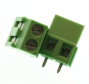
Screw terminals, as seen in Figure 29, are electrical connectors that hold wires in place with a clamping screw. They allow for a more secure connection than female headers and more flexibility than soldering a wire in place. There is one screw, socket, and pin per connection.
Sensor Modules
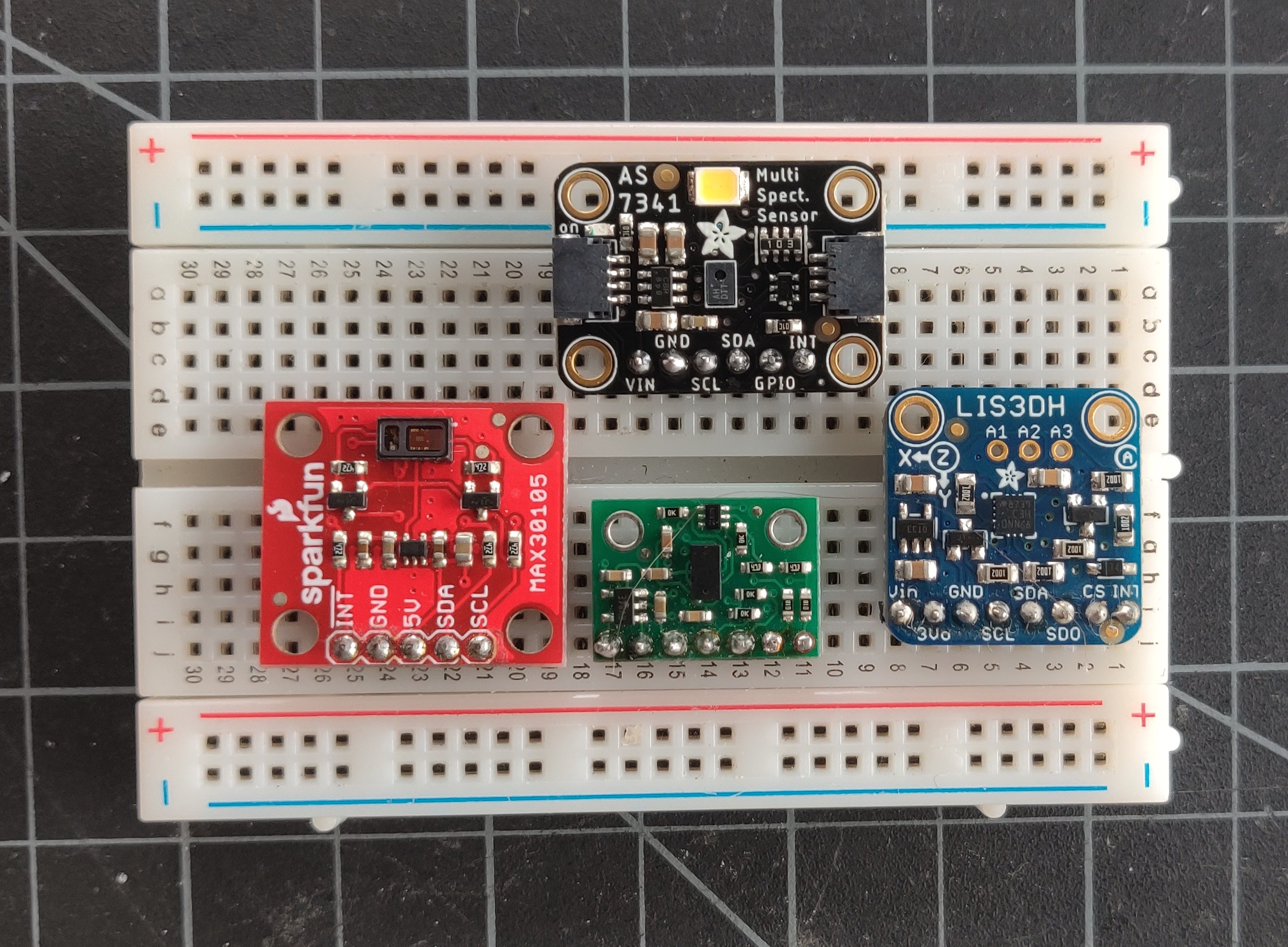
Increasingly, sensors are no longer just simple components that output a changing resistance or capacitance. Sensor modules are application-specific integrated circuits (ASICs) which read a particular physical property and give you a measurement via a synchronous serial communications channel like I2C.
Figure 30 shows four different I2C sensors: a ten-channel spectrometer, at the top, which measures the intensity of light in ten different frequencies; An accelerometer, on the right (read below for more); a time-of-flight distance ranging sensor, that measures distance using an infrared low-power laser, on the bottom; and a light sensor that functions as both a particle sensor and a pulse oximeter, on the left, by measuring the change in color of your blood through the skin of your finger.
These are only a few of the many sensor modules available that can be connected to a microcontroller via I2C. You’ll see color and gesture sensors, temperature and humidity sensors, and many more. They are often available as breadboard-friendly breakout board modules, like the ones shown here, that are typically a circuit board that’s a few centimeters square, with holes on one side spaced 0.1″ apart so you can attach pins to plug it into a breadboard.
Figure 30. Various I2C sensors
Accelerometer
Figure 31. Accelerometer, LIS3DH
Accelerometers are sensors which measure a changing acceleration (Figure 31). They are typically part of sensors called Inertial Measurement Units, or IMUs. They are useful for measuring the tilt of a body, or for measuring the force of an impact. They come in both digital and analog forms. A typical accelerometer measures acceleration along three axes, all perpendicular to each other. Accelerometers are increasingly built into microcontroller modules and other electronic devices. There is accelerometer and a gyrometer built into the Nano 33 IoT.
Infrared Distance Ranger
Sharp makes a line of infrared distance ranging sensors that measure distance in about a 1-meter range using infrared light. The one shown in Figure 32 has an analog voltage output.
Figure 32. IR distance ranger
Ultrasonic Distance Ranger
Ultrasonic distance rangers measure distance by emitting pulsed ultrasonic waves and listening for the echo from a distant object. These are sometimes used in cars to aid in detecting the distance of objects behind the rear bumper. The one shown in Figure 33 outputs a digital pulse whose pulse width varies with the distance from the target object.
Figure 33. An Ultrasonic sensor, model HC-SR04. The sensor has two cylindrical transducers, and four pins at the bottom of the board, labeled from left to right: Vcc, Trig., Echo, Ground.
Temperature and Humidity Sensors
There are dozens of temperature and humidity sensors on the market, with many different interfaces. The one shown in Figure 34, the DHT22, is very popular because it’s simple to use, reliable with a long track record, and inexpensive. It uses a one-wire interface.
Figure 34. a DHT-22 temperature and humidity sensor
Speaker
Figure 35. Photo of an 8 ohm speaker
A speaker is a paper or plastic cone mounted to a coil of wire. The coil is mounted next to a magnet. When a current is passed through the wire, it induces a magnetic field, which attracts or repulses the magnet. This makes the cone vibrate, and produce sound. The speaker shown in Figure 35 is an 8-ohm speaker.