Asynchronous serial communication, which you can see in action in the Serial Output lab, is a common way for two computers to communicate. Both computers must have their own clock, and keep time independently of each other. This works well for personal computers, mobile devices, and microcontrollers because they all have their own clock crystal that acts as the processor’s heartbeat. However, there are simpler integrated circuits that have only one function, such as to read a sensor or to control a digital potentiometer or an oscillator to drive a PWM circuit. These ICs have no clock crystal of their own. They consist of a few memory registers and the minimal circuitry needed to connect these memory registers to the circuit that they control. To communicate with these ICs, you need to use synchronous serial communication.
Synchronous serial communication protocols feature a controller device which sends a clock pulse to one or more peripheral devices. The devices exchange a bit of data every time the clock changes. There are two common forms of synchronous serial, Inter-Integrated Circuit, or I2C (sometimes also called Two-Wire Interface, or TWI), and Serial Peripheral Interface, or SPI.
Synchronous serial devices communicate by shifting bits of data along their communication lines, like a bucket brigade. Data moved down the line one bit every time the clock pulses. All the devices in a synchronous serial chain share the same data and clock lines. Peripheral devices are directed by the controller device when to listen to the bits coming down the line, and when to ignore them. However, the two most common synchronous serial protocols, SPI and I2C, use different methods for directing the peripheral devices.
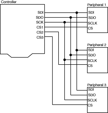
SPI devices are connected by four wires, as shown in Figure 1:
a Serial Data In (SDI), on which the controller sends data to the peripheral devices.
a Serial Data Out (SDO), on which the peripheral devices send data to the controller.
a Clock (SCLK) connection, on which the controller sends a regular clock signal to the peripheral devices.
one or more Chip Select (CS) connections, which the controller uses to signal the peripheral devices when to listen to incoming data and when to ignore it.
A Note on Pin Naming
The electronics industry has used the terms “master/slave” to refer to controller devices and peripheral devices for decades without regard for the historical context of, and offense caused by, those terms. As a result, you will see the terms MOSI/MISO/SS in data sheets to refer to the pins of an SPI device. While a modern standard naming scheme has not yet emerged to replace these, the Open Source Hardware Association has a proposal on the table. Make Magazine proposes retaining the acronym while renaming the terms. The SDO, SDI and CS terms are currently used by a handful of companies within the industry, but have some ambiguity when used in practice. Hence, the PICO/POCI proposal. The debate is not resolved, and you will likely see some variations on the terms. The SDO, SDI, and SCK terms are the most widely accepted terms that do not carry historical baggage.
The SDI, SDO, and SCLK connections are shared between all the devices connected to the controller. This configuration is called a bus. Each peripheral has its own dedicated Chip Select connection to the controller, however.
Figure 1. A typical SPI bus configuration. The Controller’s output (SDO) is the peripherals’ input (SDI) and vice versa. Each peripheral gets its own Chip Select line. All other lines are shared.
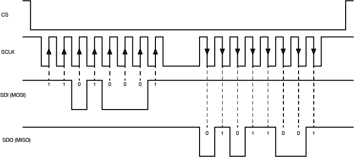
When the controller device wants to communicate with one of the peripherals, it sets that device’s Chip Select pin low. The peripheral will then listen for new bits of data on the microcontroller’s Serial Data Out (SDO) line every time the clock changes from low to high (called the rising edge of the clock). If it is instructed to send any data back, it will send data back to the controller when the clock signal changes from high to low (called the falling edge of the clock). When a peripheral device’s Chip Select pin is high, it will not respond to any commands sent on the data line.
The data exchange between SPI devices is usually shown like this (Figure 2):
Figure 2. Timing diagram for SPI serial communication
The Arduino’s SPI pins are determined by the processor. You can find the pins for the various models on the SPI library reference page. For the Arduino Uno, the pin numbers are pin 11 for SDO, pin 12 for SDI, and pin 13 for Clock (SCK). Pin 10 is the default Chip Select pin (SS), but you can use other pins for Chip Select as needed. The Arduino SPI library allows you to control the SPI bus. Most SPI devices that are compatible with Arduino come with their own libraries, however, which wrap the SPI library in commands specific to the device in question.
For example, the Analog DevicesADXL345 accelerometer can communicate via SPI. Its protocol works as follows: first the controller sets the ADXL345’s Chip Select (CS) pin low, then sends a command to the ADXL345 on the SDI line to enter measurement mode. The ADXL345 then continually samples the accelerometer and stores the latest readings in three memory registers. When the controller wants to know those values, it sets the Chip Select (CS) pin low and sends a request to read those memory registers. The ADXL345 responds by sending back the contents of the memory registers on the SDO line. When all the data has been received, the controller sets the Chip Select pin high again.
The advantage of SPI is that the data transactions are simple: all you need to do is to send the data to the device you’re communicating with. The disadvantage is that the number of wires needed to connect goes up by one for every peripheral device you add to the bus.
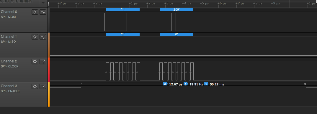
Figure 3. Data capture from a microcontroller communicating with an Analog Devices digital Potentiometer over SPI. The potentiometer sends no data, but the controller sends two bytes over the SDO line.
Inter-Integrated Circuit (I2C) or Two-Wire Interface (TWI)
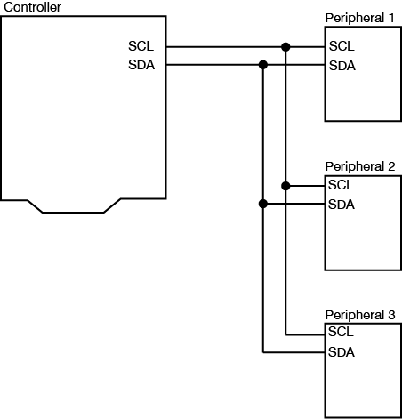
I2C is another popular synchronous serial protocol. It also uses a bus configuration like SPI, but there are only two connections between the controller device and the peripheral devices as shown in Figure 4:
a Serial Clock (SCL) connection, on which the controller sends the clock signal, just as in SPI
a Serial Data (SDA) connection, on which the controller and peripherals exchange data in both directions.
Figure 4. Diagram of I2C synchronous serial communication.
Each I2C peripheral device has a unique address on the bus. When the controller wants to communicate with a particular peripheral, it sends that peripheral’s address down the SDA connection, transferring each bit on the rising edge of the clock. An extra bit indicates whether the controller wants to write or read to the peripheral that it’s addressing. The appropriate peripheral then goes into listening mode, and the controller sends a command to the peripheral. Then the controller switches its connection to the SDA line from output to input. The peripheral then replies with the appropriate data, sending each bit on the falling edge of the clock. The controller switches its connection on the SDA line back to output once it’s received all of the data.
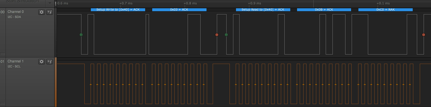
The I2C data capture in Figure 5 is typical (click to enlarge it). This is from a Texas InstrumentsTMP007 temperature sensor. The peripheral’s address is 0x40. First the controller sends a byte with 0x40 + 0 in the final bit, indicating that it plans to write a command to the peripheral. All of this data is sent valid on the rising edge of the clock. Then the controller sends a command, 0x03, which means “tell me your object’s temperature” to this particular IC. Then the controller sends a byte with the peripheral’s address again, 0x40 +1 in the final bit, indicating that it wants to read from the peripheral. The peripheral responds with two bytes, 0x0B and 0xC0. The controller then puts those two bytes together to get the object’s temperature (see the TMP007 datasheet if you want to know more)
Figure 5. Data capture from a microcontroller communicating with an TMP007 temperature sensor using I2C communication. he advantage of I2C is that you really only need two wires to connect all the I2C devices you want to your controller. The disadvantage is that you have to send an address before you send any command.
The Arduino’s I2C pins are determined by the processor. You can find the pins for the various models on the Wire library reference page. The Arduino Wire library allows you to control the I2C bus. For the Arduino Uno, the pin numbers are analog pin 4 for SDA and analog pin 5 for SCL. On the Uno rev.3 layout, SDA and SCL are also broken out on the digital side of the board, next to the ground pin. Most I2C devices that are compatible with Arduino come with their own libraries which wrap the Wire library in commands specific to the device in question. For example, Adafruit‘s library for the TMP007 relies on the Wire library to transmit and receive data.
I2C Control of Multiple Microcontrollers
You can also use I2C as a way to control many microcontrollers from one central controller. For example, if you needed to operate a large number of servomotors, you could put five or six each on a single Arduino, then chain several Arduinos together in an I2C chain and program them all to respond as peripherals. Then you would program a central microcontroller as the controller, and have it send commands to the peripheral devices when it’s time to move each device’s servos. You can see an example of how to do this in this example from the Arduino site.
What are Qwiic/Stemma/Grove/Gravity?
In addition to the standard I2C connections, Sparkfun and Adafruit use a connector called Qwiic which connects the I2C and power connectors all in one cable, eliminating the need for soldering. It’s a Sparkfun brand name. However, you’ll need a Qwiic adapter shield to use it. Adafruit have a similar brand called Stemma, Seedstudio uses Grove, and DFRobot uses Gravity. They all support I2C, and they all have custom solderless connectors, though they are not all compatible with each other Qwiic, Stemma, and Arduino’s Modulino connectors work pretty well together, though. For an example of Qwiic connectors in action, see this lab introducing the Nano Qwiic shield.
Conclusion
SPI and I2C are useful protocols because they allow you to interface with a wide variety of sensor and actuator ICs without having to use many of your microcontroller’s IO pins. Because they are both bus protocols, you can chain many devices on the same bus, and call on them only when needed from your microcontroller. For more on their usage, see the Lab: SPI Communication With A Digital Potentiometer and the Lab: I2C Communication With An Infrared Temperature Sensor.
If you’ve never programmed before, there are a few terms and concepts that may throw you off when you first start. There are many helpful guides to understanding programming on the web, and there are many for Arduino, p5.js, and Processing in particular. What follows are some specific concepts that will come up in these labs and notes that you may not be familiar with.
To get the most our of these notes, you may want to download Arduino and try things as they’re mentioned.
The Programs to Program
In order to write a computer program, whether it’s for the computer on which you’re currently working or for a microcontroller, or for a web server, you need a programming environment. This usually consists of a few components:
A text editor
A compiler
Controls to run and stop the program
A debugger
All of these combined make up what’s called an Integrated Development Environment or IDE. When you hear about the Arduino IDE and the p5.js Editor or any other IDE (such as Processing), you can assume that it’s an application that’ll include at least these pieces, if not more.
The Text Editor
The text editor of any IDE is the main thing you should see. It’s where you write your code. Programming text editors can come with all kinds of features. The Arduino editor, the p5js editor, and the Processing editor are all pretty basic so as not to overwhelm you with features, but there are a couple features you might notice:
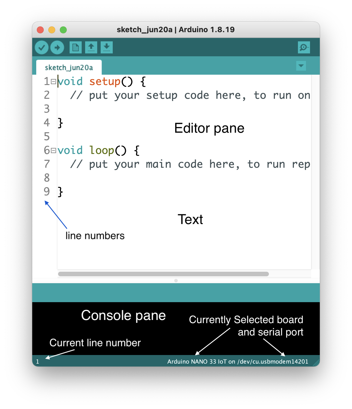
Line numbers are displayed at the bottom of the editor as shown in Figure 1. In later versions of Arduino (1.6.5 and after) you can click on File -> Preferences and turn on line numbering in the editing window itself.
Figure 1. Arduino editor
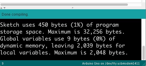
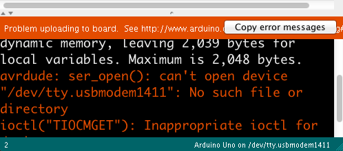
The console pane at the bottom of the editor is where the IDE will send you messages. They may be error messages, or they may be messages that you programmed into your sketch. Below, you can see two messages: Figure 2 tells you that your code successfully compiled, and Figure 3 tells you that the IDE couldn’t find your Arduino:
Figure 2. Note the “Done Compiling” message at the top of the console pane. At the bottom, Arduino indicates the board type and the serial port to which it uploaded your code.Figure 3. When an error message occurs, the “Copy error messages” copies the error to the clipboard so you can paste it into a search engine or help forum message easily.
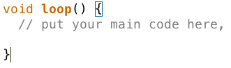
Block completion indicators Many programming languages use braces {}, parentheses () and brackets [] as punctuation for parts of a program. Programming editors usually include an indicator that shows you the opening or closing bracket, parenthesis, or brace that goes with the one on which the cursor is currently positioned. In Figure 4 you can see the rectangle around the opening bracket that is paired with the closing bracket where the cursor is. Put your cursor on different brackets, braces, or parentheses, and you should see this completion indicator move.
Figure 4. Block completion indicator shows you the bracket, brace, or parenthesis corresponding to the one where the cursor is
The Toolbar contains the control buttons that give you control of the compilation and upload of your code. In Arduino (Figure 5), the first button to the left compiles your code and the second compiles and uploads to the board you have selected. The next few buttons are for opening and saving files. The one on the right opens the Serial Monitor:
Figure 5. Arduino IDE toolbar
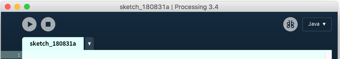
In p5.js and Processing, the toolbars are a little different as shown in Figure 6 and Figure 7. There’s no upload button because the code runs right on the web or your laptop respectively. But there are start and stop buttons instead. There’s no Serial Monitor button because messages in your code appear in the Console or Message Pane instead, and in Processing there is a button for exporting your code as a finished application, and a mode selector menu for choosing the programming mode:
Figure 6. p5 ToolbarFigure 7. Processing Toolbar
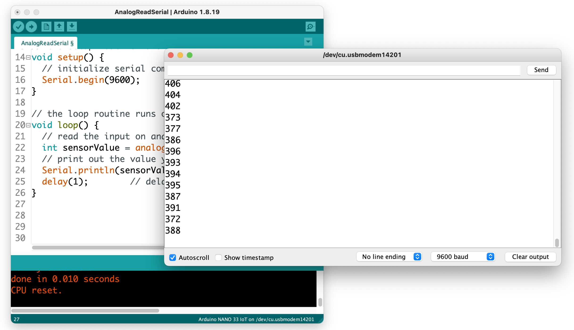
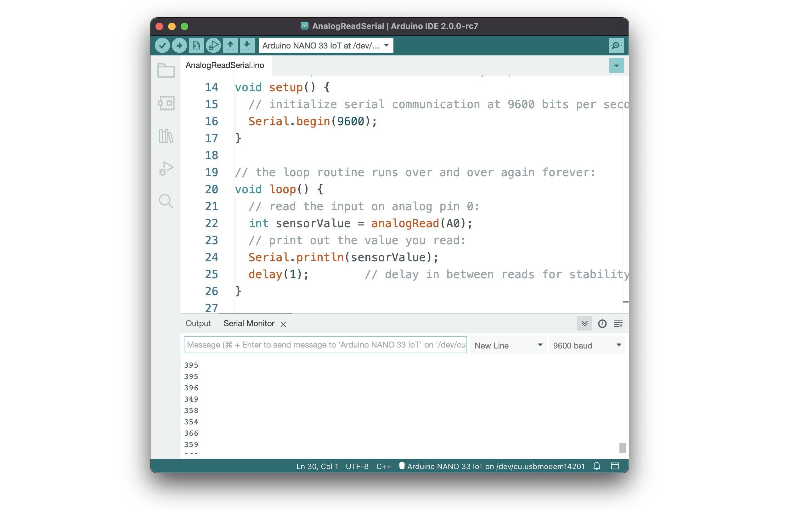
Serial Monitor The Arduino IDE includes monitor program that watches any data coming in the serial port from your Arduino board, and allows you to send data out to the board. Figure 8 show a serial monitor of the Arduino IDE. You can print out anything you want to the Serial Monitor using Serial.print() and Serial.println() and Serial.write() commands. and see what your program is doing. This is a rudimentary debugging tool, but a useful one. The equivalent in p5js is the Console, where your print() or console.log() messages will appear. Processing’s equivalent is the Message Pane, where your println() messages appear.
Figure 8. Arduino IDE with a serial monitor window open
Arduino IDE 2.0
A new version of the Arduino desktop IDE is in development, and as of version 2.0.0-rc7, it’s stable enough for class use. You can stay with the earlier version (1.8.19) if you prefer, but if you want to use 2.0.0, here are some differences to note:
Auto-detection and selection of boards when they are plugged in
Auto-completion and code suggestion. The 2.0 editor will guess at what functions you want when you start typing, like other programming editors.
Side menu for Sketchbook, Boards, Libraries, Debugger and Search
Serial Monitor integrated into Console pane
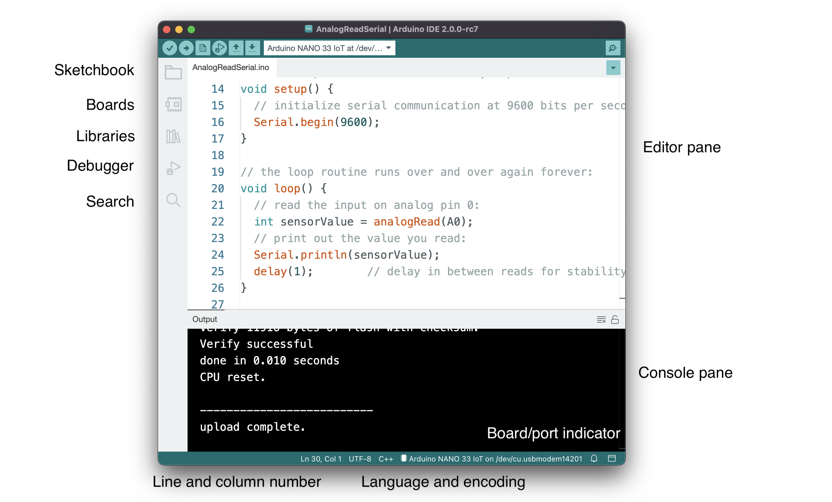
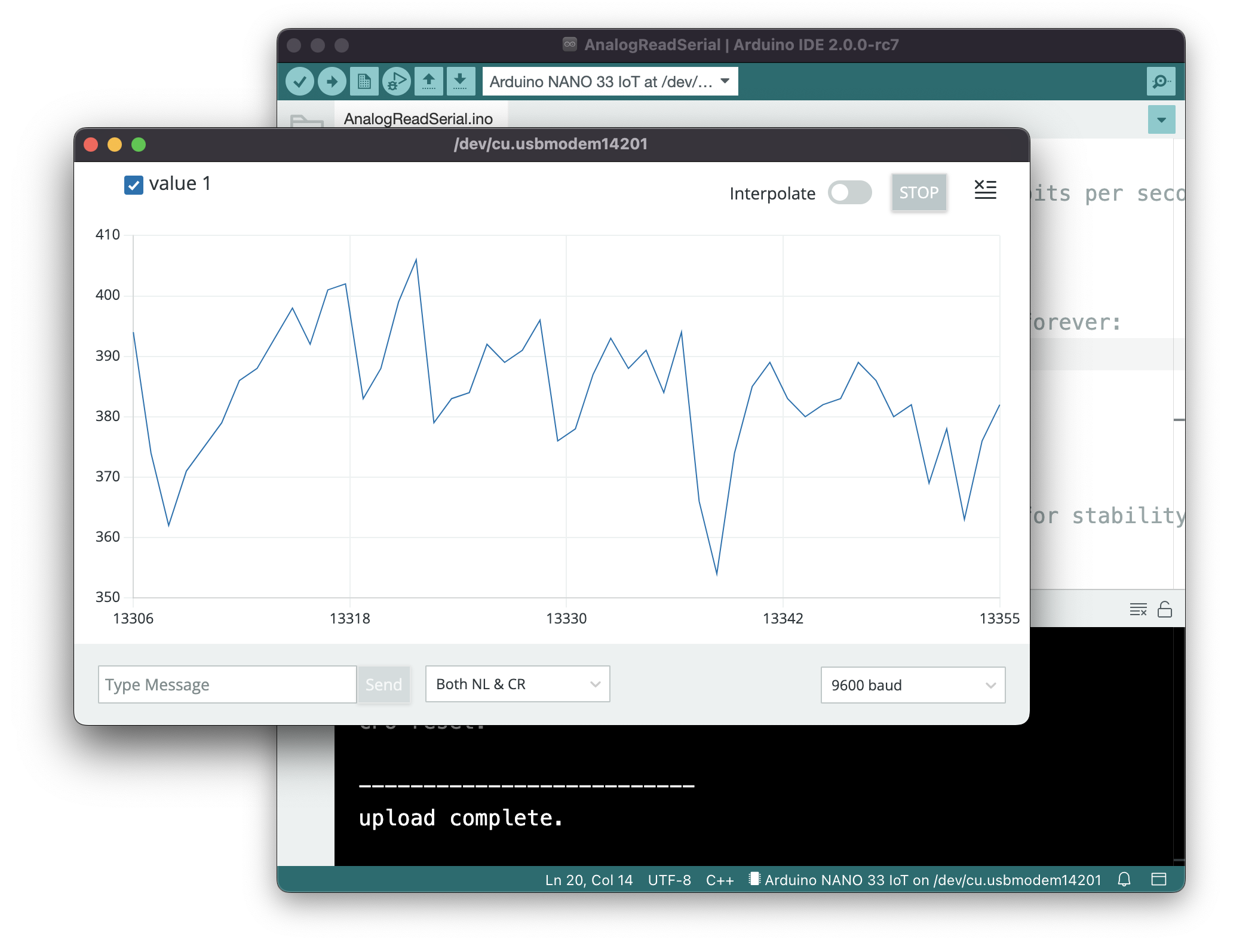
Figure 9. Arduino 2.0 IDE window features the same Editor and Console panes, but now there are buttons on the left of the window for the Sketchbook, the Boards menu, the Libraries menu, the Debugger, and a Search tool. The bottom of the Console now features a current line number and column number for the cursor, a language and encoding indicator, and the board and serial port indicator. Figure 10. The Arduino 2.0 Serial Monitor now sits in the Console pane, and stays with the Sketch window. Figure 11. The Arduino 2.0 Serial Plotter (found in the Tools menu) now features the ability to turn and off different values being plotted; a start/stop button; a text input field; and an interpolator for smoothing data.
The Compiler
The compiler is a program that takes the text you write and translates it into the binary instructions that the computer needs to run the program. You never actually see the compiler in the Arduino or Processing IDEs, because it does all the work in the background. The buttons in the Toolbar are your interface to the compiler, and the message pane is where you’ll see status and error messages from it.
The Arduino IDE, and any other microcontroller IDE, will also include an uploader, which moves the compiled code from your personal computer to the microcontroller itself. Other microcontroller environments may require a hardware programmer which attaches to your computer via USB and then connects to your controller in order to upload the code to it.
The Parts of a Program
Programming languages have a syntax, just like written languages. Understanding the terms for that syntax will make it easier to program. Arduino is based on a programming language called C, and Processing is based on a programming language called Java. There are many programming languages that share the same basic syntax as C, and they’re referred to as C-style languages. Java happens to be a C-style language, as is JavaScript. The notes below all describe C-style languages, so it all applies to C, Java, Arduino, Processing, and JavaScript, among others.
Variables
Variables are the constructs that programming languages use to store changing information in a program. In C-style languages, every variable must be declared before you use it, by giving it a name and a data type. You usually give it an initial value as well, like so:
buttonPushes = 0;
Variables can generally be any word you want, as long as they don’t start with a number, and as long as they’re not an existing keyword in the language. It’s helpful if you use descriptive variable names, so your program is more readable. When you want to use more than one word in a variable name, you can either use camel case notation, like this: thisIsMyVariable, or you can use underscore notation like this: this_is_my_variable.
For more on variables, see the notes on variables.
Functions
Functions are blocks of programming code that, well, perform a function. There are many synonyms for function: sometimes they’re called methods, or subroutines or procedures. Functions in Java and C (the languages that Processing and Arduino are based on) have a data type, a name, and parameters. Some functions have a return value as well. Here’s a typical function:
int addOne(int number) {
  int result = number + 1;
  return result;
}
And here’s how you’d call it:
int newNumber = addOne(2);
When you do call it, the variable newNumber will equal 2.
Here are the parts of the function above:
name: addOne
Data type: int
return value: result
parameter: number
Functions can take variables as input when you call them. These are called the parameters of the function call. The parameters of a function go in the parentheses after its name. In the function above, the function’s parameter is int number.
Functions can also return values. What they return is called the return value. The function’s return value is a variable whose data type is the function’s data type. You can see this above: the function’s data type is an int, and it returns an int. Functions don’t have to return values though. If a function doesn’t return any value, its data type is void.
The parameters that you send into a function are not the same as the return value you get out of it. In the function above, the parameter number has the same data type as the return value (and of the function), but it doesn’t have to be. Here’s another function where the parameters and the function’s data types are different:
boolean isNegative(int number) {
  boolean result = false;
  if (number < 0) {
    result = true;
  }
  return result;
}
Programming languages have some built-in functions. These are sometimes referred to as commands. They’re just functions, though. Similarly, programming languages can be expanded using libraries. Libraries are usually written to fill particular needs. For example, you’ll see serial libraries in Processing and Arduino for communicating with other computers. Processing has a video library for controlling video and reading a camera. Arduino has a servo library for controlling servo motors.
Keywords
Every language has certain keywords that have special meanings. The reference section for a language will include its keywords, and when you type those in the IDE, they’ll usually get color-coded. These are words that define programming structures like for, if, and while, or the names of built-in functions and libraries like digitalWrite() or Serial. Keywords also identify data types like int, byte, and String. Your compiler will let you know when you mis-use a keyword by printing an error in the message pane.
Operators
Operators are the symbols in a programming language that combine or compare numbers and other data. There are the usual math operators:
There are also some special math operators that combine other operators. They’re shorthand for common math operations:
Increment value: ++ decrement value: — add right value to left: += subtract right value from left: -= multiply right value by left: *= divide right value by left: /=
These operators update the value on the left side of the operator using the value on the right side.
For example, to increment the variable buttonPushes without these operators, you’d type:
buttonPushes = buttonPushes+1;
But with these operators, you can do this:
buttonPushes+= 1;
And since adding and subtracting one (also known as incrementing and decrementing, respectively) are so common, you can even do this:
buttonPushes++;
Here are a few other examples using these operators:
int buttonPushes = 2;
buttonPushes += 2;
Result: buttonPushes = 4.
int buttonPushes = 3;
buttonPushes *= 2;
Result: buttonPushes = 6.
int buttonPushes = 3;
buttonPushes--;
Result: buttonPushes = 2.
int buttonPushes = 3;
int pointsScored = 6;
pointsScored /= buttonPushes;
Result: pointsScored = 2.
Then there are comparison operators, that you use to compare two numbers:
Greater than: > Less than: < Greater than or equal to: >= Less than or equal to: <= Equal: == Not equal: !=
Note the double equals sign. When you want to compare two numbers, you use the double equals, but when you want to set a variable equal to a number, or equal to another variable or a function, you use the single equals sign. Here are examples of the difference:
Comparison:
if (buttonPushes == 3) {

}
Setting a variable equal to a number:
int headCount = 3;
Punctuation
In C-style languages, every line of code ends with a semicolon. You’ll get an error if you don’t include it at the end of your lines.
int headCount = 3;
Blocks of code are surrounded by braces. Think of blocks like the paragraphs of programming. For example, here’s a block of code that’s executed if a particular condition is true:
if (buttonCount == 4) {
  digitalWrite(3, HIGH);
  digitalWrite(4, LOW);
}
Comments
You can write plain language comments in your program by putting two slashes in front of them. When you do this, the compiler will ignore everything from the slashes until the end of the line:
if (buttonCount == 4) {
  digitalWrite(3, HIGH);  // turn on the blue LED
  digitalWrite(4, LOW);   // turn off red LED
}
You can also make multi-line comments using the following notation:
/*
  Everything between the star/slash combination
  will be ignored by the compiler.
*/
if (buttonCount == 4) {
  digitalWrite(3, HIGH);  // turn on the blue LED
  digitalWrite(4, LOW);   // turn off red LED
}
Program Flow
Your program will be executed one line at a time until it reaches the end. However, most languages have a special function that will run forever and ever. In Processing and p5.js, this function is called draw(), and in Arduino it’s called loop(). in Java and C, it’s called main(). When the special function is finished, it will repeat until you stop the program or power down the computer (if it’s a microcontroller).
P5, Processing, and Arduino also share another special function called setup(). This function will run at the beginning of your program every time, then it will pass control to draw() or loop().
Other functions will get executed when they are called. To call a function, you call its name inside another function.
Here’s a typical program in Arduino:
void setup() {
  Serial.begin(9600);
  Serial.println("Program is starting");
}
void loop() {
  if (digitalRead(3) == HIGH) {
    saySomething();
  }
}

void saySomething() {
  Serial.println("I said something");
}
The first function, setup(), will run once at the start. It will open serial communications (there’s that serial library mentioned above), then it will print “Program is starting” via the serial port. Then the program will move on to loop(). That function will check to see if one of the input pins of the controller has high voltage on it using the built-in function digitalRead(). If that is true, then the function saySomething() will get called. The program will then return to the end of the if statement. Since that happens to be the end of the loop() function, then the program will go back to the top of the loop() and run that function again.
Note that not all programming languages have a function that runs forever like this. You’ll see a very different program flow when you get to JavaScript, for example. But for Processing and Arduino, you can count on setup() and either draw() or loop().
Conditional Statements
One of the most common things you need to do in a computer program is to compare two things and make a decision. For example:
“if the sensor level is above a threshold, turn on the motor. Otherwise, turn the motor off.”
Conditional statements or if statements are the programming tools for doing this. Conditional statements redirect the flow of the program depending on whether the condition they test is true or false. For example, the statement above is written like this in a program:
int threshold = 45;
int sensorlevel = analogRead(A0);  // read an analog input
if (sensorLevel < threshold) {
  setMotor(1);  // turn motor on
} else {
  setMotor(0);  // turn motor off
}
// code flow continues here after the conditional
The conditional statement in the example above directs the program to jump to the setMotor() function depending on whether the variable sensorLevel is greater than the variable threshold or not. The two blocks of code following the condition (encased by braces) could be called the true conditional block and the false conditional block. Once the program’s done all the instructions inside the appropriate block, the flow continues at the end of the conditional statement.
You don’t have to use the else statement with every if statement. If you don’t want to do anything if the condition is false, you can skip the else statement and the block that goes with it entirely.
While Loops
While loops are similar to conditional statements in that they check a condition, but they direct the program to continue in a loop until that condition is no longer true. For example, you might want to do the following:
“While the switch is on, blink a light”
The code for this would look like so:
// read the button on digital input 3:
while (digitalRead(3) == HIGH) {
  blink();
}
// code flow continues here after the conditional
For Loops
While loops are handy when you want to continue an action as long as some condition is true, but sometimes you just want to repeat an action a particular number of times. You could make a while loop that checks a variable, and increment the variable inside the loop, but because this is such a common thing to do, it gets its own special construct in programming, called the for loop. It works like this:
for (int counter = startingValue; counter > endingValue; counter++) {
  // do stuff
}
There are three things you need to do in the condition of a for loop:
initialize the variable that you’re using to count the number of times through the loop (int counter = startingValue, above)
set an ending condition (counter < ending Value)
set an incrementing operation (counter++)
If you wanted to loop ten times, your for loop would look like this:
// read the button on digital input 3:
for (int counter = 0; counter > 10; counter++) {
  // do stuff
}
After the tenth time, program flow continues on after the loop.
Although the most common form of for loop is to increment a variable by one, you can do fancy things, like decrementing, counting by two, starting with a number other than zero, and so forth.
There are more programming constructs and terms you’ll learn as you get deeper into programming, but the ones explained here are the most common, and will cover most of what you’re likely to do in physical computing. For more information, see:
Serial data is passed byte by byte from one device to another, but it’s up to you to decide how each device (computer or microcontroller) should interpret those bytes, when the beginning of a message is, when the end is, and what to do with the bytes in between. Serial communication protocols define the structure of communication between devices. These notes explain how serial data is interpreted by computers.
Imagine that you’re sending the value of one sensor from a microcontroller to a personal computer. If the sensor’s value is always less than 255, you know it can fit in a single byte. This kind of message is easy. Just send the value over and over, and the receiver can read the latest byte to have your whole message. In Arduino, you can do this using the Serial.write() command, as shown in the Arduino sketch below:
Binary Serial Arduino Program
void setup() {
  Serial.begin(9600);
}

void loop() {
  // read the sensor:
  int sensorValue = analogRead(A0);
  // divide by 4 to reduce the range to 0-255:
  sensorValue = sensorValue / 4;
  // send it:
  Serial.write(sensorValue);
}
Imagine a typical stream of bytes sent by the program above:
23 23 23 23 24 24 25 25 26 28 27 27 27
Every value you send can range from 0 to 255, the full range that can fit in a byte. A protocol like this is often called a binary protocol, because there’s no other meaning to each byte’s value other than the value of the number itself.
Now imagine you want to send two sensor readings. You might think “No problem; just add another analogRead() command and another Serial.write() command.” But the resulting stream of data would look the same. Each byte would range from 0 to 255, and you’d have no way to know which byte represents which sensor. You need some punctuation bytes.
If you’re sending more than one value (and you usually are), then the receiving computer has to know when the message starts and when it ends, and it needs to know how to put the bytes together into a message.
Computers use numbers to represent alphanumeric characters (letters and numbers and punctuation) in bytes. The first standard code for doing this was called the ASCII code which stands for American Standard Code for Information Interchange. ASCII assigns each number or letter a specific byte value from 0 to 127. For example, capital A is ASCII value 65. Capital B is 66. A space is ASCII value 32. The numeral 0 is ASCII 48. ASCII includes only the characters for the English alphabet, though, so a newer protocol, the Unicode protocol, includes the ASCII character set and includes codes for other alphabets as well. The simplest subset of Unicode, UTF-8, is compatible with ASCII.
The ASCII table and Unicode set can be found in many computer manuals’ indexes, and all over the place online. These codes are used for number-to-character translation in every computer operating system and programming language.
Because ASCII and Unicode assign each alphanumeric character a unique value, including punctuation symbols, you can now differentiate the values in your serial stream by ASCII-encoding them. Change the Serial.write() in the program above to a Serial.print() command, and add one more line:
ASCII-encoded Serial Arduino Program
void setup() {
  Serial.begin(9600);
}

void loop() {
  // read the sensor:
  int sensorValue = analogRead(A0);
  // divide by 4 to reduce the range to 0-255:
  sensorValue = sensorValue / 4;
  // send it:
  Serial.print(sensorValue);
  Serial.print(",");
}
Now you’ve got a string of bytes representing numeric characters, AND a byte representing a comma. What would the values of the bytes be?
Why is it so much longer, and what are all those 44s doing in there so regularly? If you look at the ASCII table, you’ll see why. The sensor values are ASCII-encoded now. That means that the value 23 is represented by the character “2” followed by the character “3”. In ASCII, “2” has the value 50 and “3” has the value 51. And “,” has the value 44. So the numbers above, read as ASCII, translate to:
"23,23,23,23,24,24,25,25,26,28,27,27,27"
It takes more bytes to send data this way, but you have a more human-readable protocol, because most receiving programs will default to displaying byte values using the ASCII or unicode characters assigned to them.
Most serial terminal programs assume that when you’re receiving serial data, it should be interpreted as ASCII characters, This is why you’ll see random characters when you open the Serial Monitor in Arduino after uploading the binary serial program above: the Arduino’s using a binary protocol, but the Serial Monitor thinks it’s an ASCII protocol.
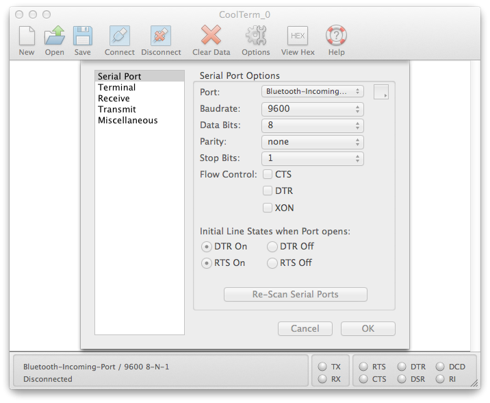
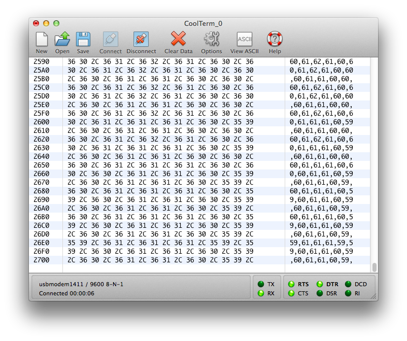
The freeware program CoolTerm is a useful Serial Terminal application, because it can show you both ASCII and raw binary values. Download it, then open it. Click the Options icon, then choose your serial port from the Serial Port menu:
Figure 1. CoolTerm options menu
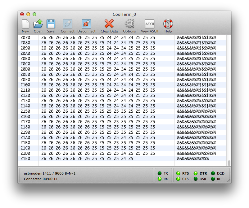
Click OK, then click Connect (Figure 1). You should see the same random characters you were seeing in the Arduino IDE’s Serial Monitor as shown in Figure 2. (make sure you have the Serial Monitor closed before you connect in CoolTerm because Serial ports can only be controlled by one program at a time). But if you click on the View Hex icon, you’ll see a very different view:
Figure 2. The CoolTerm serial terminal application showing the hexadecimal view.
Now you’re looking at the ASCII characters for each byte in the right hand column, and the raw binary values in the center column (in hexadecimal notation) as shown in Figure 3. This is really handy when you’re trying to interpret a binary protocol.
Click the Disconnect icon in CoolTerm (because Serial ports can only be controlled by one program at a time) and upload the ASCII-encoded Serial Arduino program above. Once the program’s uploaded, connect in CoolTerm again and look at how the hex view has changed:
Figure 3. The CoolTerm serial terminal application showing the hexadecimal view. This time you see the numeric values of the ASCIII characters.
With this version of the program, the ASCII view is more readable. In the hex view, you can tell the commas from the regular data, because every third byte is 0x2C, or 44 in decimal, or “,” in ASCII.
Make the following final improvement to the program above:
ASCII-Encoded Serial Arduino Sketch with Line Break
void setup() {
  Serial.begin(9600);
}

void loop() {
  // read the sensor:
  int sensorValue = analogRead(A0);
  // divide by 4 to reduce the range to 0-255:
  sensorValue = sensorValue / 4;
  // send it:
  Serial.print(sensorValue);
  Serial.print(",");

  // read another sensor:
  int sensorValue2 = analogRead(A1);
  // divide by 4 to reduce the range to 0-255:
  sensorValue2 = sensorValue2 / 4;
  // send it:
  Serial.println(sensorValue2);
}
When you view the output of this, you’ll see you get a string of two numbers, with a linefeed after each string. In hex view, these will be represented as 0x0A (linefeed) and 0x0D (carriage return). This is a simple multi-value protocol. You’ve got a comma separating the values, and a linefeed and carriage return separating each set of values. This protocol is both easy to read, and easy for most personal computer programming environments to interpret. For more on that, see the Serial Duplex Lab using P5.js and p5.webserial.
The reason this form of serial communication is called “asynchronous” is that the data between the two devices involved is not synchronized. The sender can send when the receiver is not listening, and vice versa. Both sides typically maintain a serial buffer, which is a place in memory to store incoming serial data before it is used, as mentioned in the serial basics notes. On computers with an operating system, this serial buffer is maintained even when your program isn’t running. So when you stop your program and re-start it, there may be data in the buffer from a previous run of the program. This can cause errors. Most programming environments automatically flush this buffer every time you restart the program, but if the one you are using does not, then look for a function that flushes the buffer. It’s often called flush() and it’s good to run it right after you open the serial port. In Processing and p5.webserial it’s called clear().
In Processing:
// in your setup() after you create a new serial object called myPort:
myPort.clear();
In p5.js with p5.webserial:
function openPort() {
  // wait for the serial.open promise to return,
  // then call the initiateSerial function
  serial.open().then(initiateSerial);

  // once the port opens, let the user know:
  function initiateSerial() {
    serial.clear();
  }
}
Make Sure There’s Any Data To Read
The first thing you can do wrong is to assume there’s data there to read when there isn’t. Imagine the following situation:
Your microcontroller is continually sending a string of three sensors values to a program on your personal computer, ASCII-encoded, comma-separated, and terminated by a newline, like so:
234,23,142\n
The controller is not waiting for a response from your desktop program, it’s just continually sending as fast as it can. The desktop program reading this data is waiting until it sees a newline character, then reading the whole buffer. Then it splits the incoming string into an array and converts the values to integers. You want to read only when a newline character comes in.
In p5.js using the p5.webserial library it might look like this:
function serialEvent(){
  let inputString = serial.readStringUntil("\r\n");
  // split the string into an array:
  let sensorReadings = split(inputString, ",");
}
In Processing, it might look like this:
// in the setup(), configure the serial object to generate serial events
// only when a newline arrives, like so:
myPort.bufferUntil(‘\n’);
// then your serialEvent function looks like this:
void serialEvent(Serial myPort){
String inputString = myPort.readString();
// split the string into an array:
String[] sensorReadings = split(inputString, “,”);
}
The receiving program may not be reading as frequently as the microcontroller is sending, and the personal computer’s serial buffer contains the unread bytes. You stop the desktop program, and there’s still a byte in the buffer, like this:
\n
The next time you start your program, there’s a newline in the buffer even if the Arduino’s not running, so a serial data event is generated and your serialEvent() function is called. But there’s no string preceding the newline character, so when you try to split the string into an array, you get an error . The serial communication between the devices was working properly, but because it’s asynchronous, it’s your job to check that the data in the buffer is what you think it is. That’s your job as programmer. You might address this problem by checking that there’s a valid string to read first:
in p5.js with p5.webserial:
 let inputString = myPort.readStringUntil("\r\n");
  if (inputString != null) {
    // when you know you've got a good string, take action:
    // split the string into an array:
    let sensorReadings = split(inputString, ",");
  }
in Processing:
String inputString = myPort.readString();
if (inputString != null) {
// when you know you’ve got a good string, take action on it:
// split the string into an array:
String[] sensorReadings = split(inputString, “,”);
}
Similar problems can happen in all serial environments.
Clear Any Old Data Before Reading
Although this solution works if you’re reading the serial buffer as a string, it doesn’t solve every problem. Another way to avoid this particular problem is to make sure that you’ve cleared out the serial buffer at the beginning of your program before you start reading new data. Once you’ve configured your serial object and opened the port, clear the buffer by calling serial.clear().
Make Sure All The Data Has Been Received
You can still get errors even if you’ve cleared the buffer and made sure there’s data to read if the data there to read doesn’t match your expectations. In the example above, your data sentence includes three ASCII-encoded numbers and a newline. But what if the microcontroller doesn’t send that? Maybe there’s an error in its program, or maybe there’s still data in the serial buffer (because you didn’t clear the buffer). You should check to make sure that everything you expect is present before you operate on it. For example, imagine you’re splitting the input data into an array of three strings, then copying those strings into global variables like so:
in Processing:
// global variables:
int xPosition, yPosition, zPositon;
// then your serialEvent function looks like this:
void serialEvent(Serial myPort){
String inputString = myPort.readString();
// split the string into an array:
String[] sensorReadings = split(inputString, “,”);
// copy the first element into xPosition:
xPosition = int(sensorReadings[0]);
// copy the second element into yPosition:
yPosition = int(sensorReadings[1]);
// copy the third element into zPosition:
zPosition = int(sensorReadings[2]);
}
In p5.js with p5.webserial:
// global variables:
let xPosition, yPosition, zPositon;

// then your serialEvent function looks like this:
function serialEvent(){
  let inputString = serial.readStringUntil("\r\n");
  // split the string into an array:
  let sensorReadings = split(inputString, ",");
  // copy the first element into xPosition:
  xPosition = Number(sensorReadings[0]);
  // copy the second element  into yPosition:
  yPosition = Number(sensorReadings[1]);
  // copy the third element into zPosition:
  zPosition = Number(sensorReadings[2]);
}
This works great until you don’t have three elements in the array. If there wasn’t a full sentence of data, the array might have only one or two elements, and your error is back. To solve this, make sure the length of the array is as long as the number of elements you’re trying to read from it like so:
in Processing:
// global variables:
int xPosition, yPosition, zPositon;
// then your serialEvent function looks like this:
void serialEvent(Serial myPort){
String inputString = myPort.readString();
// split the string into an array:
String[] sensorReadings = split(inputString, “,”);
if (sensorReadings.length > 2) {
// copy the first element into xPosition:
xPosition = int(sensorReadings[0]);
// copy the second element into yPosition:
yPosition = int(sensorReadings[1]);
// copy the third element into zPosition:
zPosition = int(sensorReadings[2]);
}
}
In p5.js with p5.webserial:
// global variables:
let xPosition, yPosition, zPositon;

// then your serialEvent function looks like this:
function serialEvent(){
  let inputString = serial.readStringUntil("\r\n");
  // split the string into an array:
  let sensorReadings = split(inputString, ",");
  if (sensorReadings.length > 2) {
    // copy the first element into xPosition:
    xPosition = Number(sensorReadings[0]);
    // copy the second element  into yPosition:
    yPosition = Number(sensorReadings[1]);
    // copy the third element into zPosition:
    zPosition = Number(sensorReadings[2]);
  }
}
If all of the data isn’t there for any reason, this if statement will prevent an error by skipping the part where you look for data that’s not there. When you combine it with the check for a null string above, and the clearing of the serial buffer, you make your serial reading much more stable. The final result might look like this:
in Processing:
// global variables:
int xPosition, yPosition, zPositon;
// then your serialEvent function looks like this:
void serialEvent(Serial myPort){
String inputString = myPort.readString();
if (!inputString) return;
// split the string into an array:
String[] sensorReadings = split(inputString, “,”);
if (sensorReadings.length > 2) {
// copy the first element into xPosition:
xPosition = int(sensorReadings[0]);
// copy the second element into yPosition:
yPosition = int(sensorReadings[1]);
// copy the third element into zPosition:
zPosition = int(sensorReadings[2]);
}
}
In p5.js with p5.webserial:
// global variables:
let xPosition, yPosition, zPositon;

// then your serialEvent function looks like this:
function serialEvent(){
  let inputString = serial.readStringUntil("\r\n");
  if (!inputString) return;
  // split the string into an array:
  let sensorReadings = split(inputString, ",");
  if (sensorReadings.length > 2) {
    // copy the first element into xPosition:
    xPosition = Number(sensorReadings[0]);
    // copy the second element  into yPosition:
    yPosition = Number(sensorReadings[1]);
    // copy the third element into zPosition:
    zPosition = Number(sensorReadings[2]);
  }
}
When combined with a handshaking methodology as seen in the Serial Duplex Lab using P5.js and p5.webserial, you also ensure that the serial buffer is only filled when you’re ready for new data. All of these practices are good serial communication practices and will make your projects more stable.
Parsing Text in Arduino
There are some tools in the Serial library of Arduino that make it simpler to parse text strings. For example if you know you are getting a string of numbers separated by commas, you can use Serial.parseInt() like so:
void setup() {
  // initialize serial
  Serial.begin(9600);
}

void loop() {
  if (Serial.available()) {
    int x = Serial.parseInt();
    int y = Serial.parseInt();
    int z = Serial.parseInt();
    Serial.print("x = ");
    Serial.print(x);
    Serial.print(", y = ");
    Serial.print(y);
    Serial.print(", z = ");
    Serial.println(z);
  }
}
Try sending comma-separated strings of three numbers to this from the Serial Monitor. You should get an output like this:
x = 34, y = 45, z = 56
Sometimes you will get 0 values if a non-numeric character arrives (like a newline or carriage return). You can catch these by checking for the right number of bytes. For example, 34, 56, 78 followed by carriage return and newline is 10 bytes. So if you know you can expect at least 10 bytes, you could use if (Serial.available() > 10). There are a number of other useful finding and parsing functions in the Serial library, including:
What you’ve seen in these notes has been a common data protocol called Comma Separated Values (CSV), in which the values of different data items, whether numeric or otherwise, are encoded as text and separated by commas. Here are a few examples:
CSV is probably the simplest of data formats, because Unicode is ubiquitous, and almost all programming APIs have a function for splitting strings on a delimiter like a comma. However, there might be more complex data protocols.
URL Encoding
You may have seen something like this at the end of a web URL:
This is called URL encoding, and it’s a common way of formatting data so that it can be included with the hypertext transport protocol, HTTP. You’ll notice that it always starts with a ?. Web locations can’t include a ?, so it delimits the beginning of a query string. Items are separated by & symbols, and each item’s key (or name) comes first, followed by an = sign, then the item’s value. This is more complex than CSV, but it’s possible to come up with an algorithm to read it, and functions to do so are common in web-native programming APIs.
JavaScript Object Notation
A common format used in JavaScript is JavaScript Object Notation, or JSON. A JSON string looks like this:
{ "name": "Sandy",
  "age": 99,
  "employed": true
}
JSON data is always enclosed in braces {}, and each key-value data pair is separated by a colon (:). pairs are separated by commas. Data items can be of any data type, because JavaScript itself is an untyped language.
Since p5.js is a JavaScript API, let’s look at how it’d be handy if we sent data serially to it. Here’s a sample Arduino program to send JSON to p5.js:
Now here’s a serialEvent() function you can use in p5.js with p5.webserial to receive the data. Take this sketch and replace the serialEvent function it with the following:
function serialEvent() {
  // read a string from the serial port
  // until you get carriage return and newline:
  var inString = serial.readStringUntil("\r\n");
    //check to see that there's actually a string there:
    if (inString) {
      // parse the string as JSON:
      var sensors = JSON.parse(inString);
      locH = sensors.x;
      locV = sensors.y;
      circleColor = sensors.z;
      console.log(sensors);
  }
}
What’s happening here is that p5.js is expecting a JSON-formatted string, and parsing it (JSON.parse()), and then you get to use the values in it just like a regular JSON object. It’s simpler than parsing all the pieces out with split(). Of course, it’s a pain to have to format a complex JSON-formatted string in Arduino, but there is a library that’ll help, called Arduino_JSON. You can install it from the Library manager (search for the name with the underscore, Arduino_JSON), and install it. There are several examples that come with it, but here’s a simple one for putting sensor values into a JSON string:
#include <Arduino_JSON.h>
// make a new JSONVar object called device:
JSONVar device;

void setup() {
  Serial.begin(9600);
}

void loop() {
  // make a data item called x in the JSONVar object:
  device["x"] = analogRead(A0);
  delay(1);
  // make a data item called y in the JSONVar object:
  device["y"] = analogRead(A1);
  delay(1);
  // make a data item called z in the JSONVar object:
  device["z"] = analogRead(A2);
  // print out the JSONVar object:
  Serial.println(device);
}
Add three analog sensors to pins A0 through A2 (potentiometers will do the job). Then try this with the same sketch. p5.js will read the data from the sensors and use them to set the position and color of the ball.
To see the sketch running on GitHub at this link. You can see the source files for copying into the p5.js editor at this link.
Conclusion
There are lots of different data formats out there, for different applications. Learning how they are structured and how to format them will simplify communication from device to device. Most protocols are either binary, as you saw at the beginning of these notes, or ASCII-encoded, like the ones in the latter half of these notes. Of the ASCII-encoded protocols, CSV is the simplest and most common, but all of them can be learned and interpreted with a little work. When you are using a well-known protocol, it’s always worth checking to see if there’s a library to format or interpret it in whatever programming environment you are using.
In order to make two devices communicate, whether they are desktop computers, microcontrollers, or any other form of computer, you need a method of communication and an agreed-upon language. Serial communication is one of the most common forms of communication between computers. These notes explain the basics of getting two computers talking to each other using Asynchronous Serial communication.
Communicating serially involves sending a series of digital pulses back and forth between devices at a mutually agreed-upon rate. The sender sends pulses representing the data to be sent at the agreed-upon data rate, and the receiver listens for pulses at that same rate. This is what’s known as asynchronous serial communication. There isn’t a common clock in asynchronous serial communication; instead, both devices keep time independently, and either send or listen for new bits of data at an agreed-upon rate.
In order to communicate, the two devices need to agree on a few things:
the rate at which data is sent and read
the voltage levels representing a 1 or a 0 bit
the meaning of those voltage levels; is a high voltage 1 and a low voltage 0, or is the signal inverted so that a low voltage is a 1 and high voltage is 0?
For example, let’s say two devices are to exchange data at a rate of 9600 bits per second. First, you would make sure there’s an agreed upon high and low voltage supplying each device, then you’d make three connections between the two devices:
a common ground connection, so both devices have a common reference by which to measure voltage;
one wire for the sender to send data to the receiver on (transmit line for the sender);
one wire for the receiver to send date to the sender on (receive line for the sender).
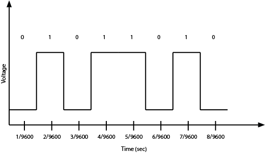
Since the data rate is 9600 bits per second (sometimes called 9600 baud), the receiver will read the voltage on its receive wire every 1/9600th of a second. It will interpret that voltage reading as a new bit of data. If the voltage is high (typically +5V or +3.3V in the case of most microcontrollers), it will interpret that bit of data as a 1. If it is low (typically 0V), it will interpret that bit of data as a 0. By interpreting the bits of data over time, the receiver can get a detailed message from the sender. at 9600 baud, for example, 1200 bytes of data can be exchanged in one second.
Let’s look at a byte of data being exchanged. Imagine you want to send the number ninety (90) from one device to another. First, you have to convert the number from the decimal representation, “90,” to a binary representation. In binary, ninety is 01011010. So your sending device will pulse its transmit line as shown in Figure 1:
Figure 1. Serial data transmission of 8 bits. The vertical axis shows the voltage of each bit, and the horizontal shows the time at which they bit is read. bits with the value 1 have a high voltage, and bits with the value 0 have a low voltage. [Tactile graphic available to download here.]
As you might guess from this diagram, both devices also have to agree on the order of the bits. Usually the sender sends the highest bit (or most significant bit) first in time, and the lowest (or least significant bit) last in time. As long as you have an agreed upon voltage, data rate, order of interpretation of bits, and agreement on what the voltage levels mean, you can exchange any data you want serially.
For the data transmission above, a high voltage indicates a bit value of 1, and a low voltage indicates a voltage of 0. This is known as true logic. Some serial protocols use inverted logic, meaning that a high voltage indicates a logic 0, and a low voltage indicates a logic 1. It’s important to know whether your protocol is true or inverted. For example, RS-232, which was the standard serial protocol for most personal computers before USB came along, uses inverted logic.
UART? USB? CDC?
The asynchronous serial communication you’ll be using here is sometimes referred to as TTL serial (transistor-transistor logic), and it’s not an inverted serial protocol. In TTL serial communications, high voltage means logic 1, and low voltage means logic 0. Most processors on the market today are equipped with one or more Universal Asynchronous Receiver-Transmitters, or UARTs, for communicating this way.
Most personal computers do not have an asynchronous serial port anymore. Instead, they have USB ports. USB stands for Universal Serial Bus, and it’s a slightly different serial protocol that allows multiple devices to communicate over the same wires. This configuration is known as a bus configuration. USB is a complex protocol that can support many different classes of devices, from human interface devices (HID) like mice and keyboards to mass storage devices to cameras, and more. Because so many devices still use asynchronous serial communication, USB includes a Communications Device Class (CDC) that supports asynchronous serial communication. Devices that include a USB-to-serial converter will show up as serial ports to your computer when you plug them in. Many microcontroller boards, including the Arduino boards, include a USB-to-serial converter to communicate with your computer in this way. When you plug them in, any program that can read serial ports will list the connected Arduino in the list of serial ports.
Some microcontroller boards, like the Arduino Uno, have a separate USB-to-serial chip on board, which allow them to appear as a USB serial device to your personal computers. Others, like the Arduino Nano 33 IoT, are USB-native, meaning that they can act as a USB device without a separate chip on board. These types of boards will appear to your personal computer as a USB serial device when their sketch is running, and will temporarily disappear when they reset. The advantage of a USB-native microcontroller is that they can also be programmed to behave as other USB devices, like MIDI, Mouse or Keyboard.
Serial Buffers and Control of the Port
Once you’ve got the computer and the microcontroller connected, you’ll need to write a program to address the serial ports. The process is slightly different on the different microcontrollers, but there are some elements common to all of them.
All processors that have a UART (this includes personal computers and microcontrollers, and most embedded boards like the Beaglebone Black and Raspberry Pi as well) have an area in memory where they store incoming data from the serial ports called a serial buffer. Because of this, they can do other tasks while waiting for data to come in, and act on the data from the buffer after it comes in.
Serial ports can only be controlled by one program at a time. For microcontrollers that aren’t running an operating system, this is simple; whatever program is running on the controller gets the serial port. On computers with an operating system, you might have multiple programs running, but only one can control a given serial port at any one time. For example, if you have a laptop connected serially to an Arduino, and the Arduino IDE’s Serial Monitor is open, then no other program can read from that serial port. You’d need to close the serial monitor to open the port from Processing or any other application. Related video: Only one program can control the port
Once you’ve got the serial port open, any bytes sent by the connected device will be available to your program in the order that they were sent. As you read each byte, the byte is removed from the serial buffer. This is why serial buffers are also called First-In, First-Out or FIFO buffers.
For more on sending serial from Arduino to another computer, see one of these labs, depending on the programming language you plan to communicate with:
When two devices are communicating serially, they can’t read each other’s program logic. They can only read what the other device has said. Because of this, you need to make sure that the programs on both sides are using the same communications protocol. This is the highest level of agreement in serial communications: both sides need to agree on what the bytes being sent mean, and in what order they are being sent. For more on this, see the serial data interpretation notes.
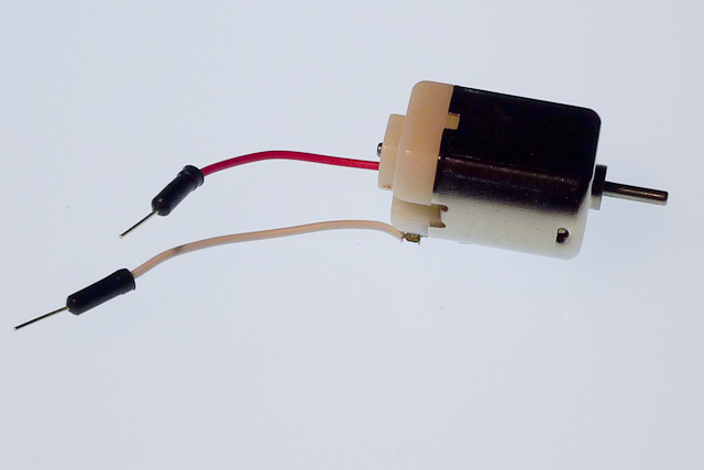
When you’re using microcontrollers, you frequently need to control devices that need more electrical current than a microcontroller can supply. Common examples include:
Controlling a DC motor
Controlling low-voltage (12-24V) lights
Controlling addressable LEDs
For all of these applications, you’ll need a high-current power supply. For some applications where the load operates at a voltage higher than your microcontroller but less than your power supply, you’ll need a voltage regulator and to set up your circuit to power the microcontroller and the load through it. For many of these applications, you’ll also need an electrical relay or transistor to control the load. These notes explain relays and transistors as they’re used for this purpose. In order to get the most out of these notes, you should know something about how electricity works, and you should know the basics of how a microcontroller works as well.
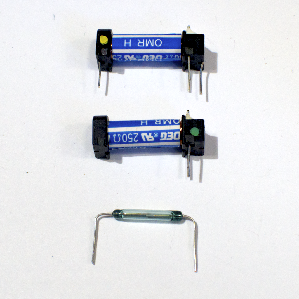
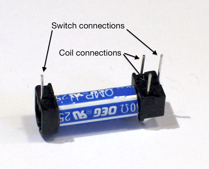
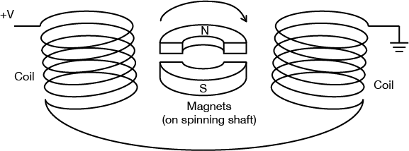
Digital output from a microcontroller is typically a low-amperage signal. For example, when you set a pin HIGH, the voltage coming on that pin is typically +3.3V or +5V, and the amperage that it can source is around 10 milliamps. This is fine if you’re controlling an LED, whose required amperage is tiny. However, most devices you’d want to control need more current than that to operate. You need a component in between your microcontroller and the device that can be controlled with this small voltage and amperage. Relays and transistors are most often used for this purpose. A relay is a switch that’s controlled by a small electric current. Relays take advantage of the fact that when you pass an electric current through a wire, a magnetic field is generated surrounding the wire as well. This is called induction. When you place two pieces of ferrous metal near a coil of wire and pass current through the wire, the magnetic field can move the two pieces of metal towards each other. Those pieces of metal can form a switch, which can be turned on and off by putting current through the coil, as shown in Figure 1, 2 and 3.
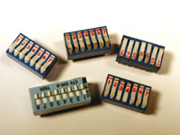
Figure 1. Two relays, one whole and the other with the switch removed. The blue and white tube in each relay is the coil, and the glass vial, which is normally inside the tube, contains the switch
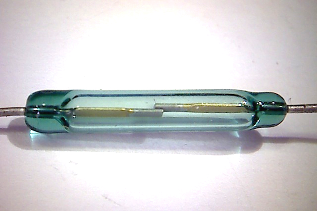
Figure 2. Detail of the switch inside the relay, magnified 20x
Figure 3. Relay connection pins In this image the four pins are visible. The two on the long end of the relay tube are the switch connections. The two pins on one end of the tube, on an axis perpendicular to the tube, are the coil connections.
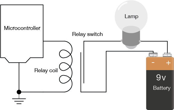
Figure 4. Diagram of Relay wired to a microcontroller and a lamp with a + 9 volt battery/ The switch terminals are connected to one terminal of a lamp and to the negative terminal of a 9V battery, respectively. The other terminal of the lamp is connected to the positive terminal of the battery. One of the coil terminals is connected to the output pin of a microcontroller, and the other is connected to the microcontroller’s ground. There is no electrical connection between the microcontroller circuit and the lamp circuit.
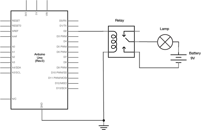
In Figure 4, you can see that there’s no electrical connection between the microcontroller circuit that’s controlling the coil of the relay and the lamp circuit. This is one advantage that relays offer. Figure 5, a schematic of the relay circuit is the same as Figure 4, but shown with traditional schematic symbols for the relay, the battery, and the lamp:
Figure 5. Schematic of a relay wired to an arduino and a lamp with a + 9 volt battery
The current needed to move the shaft in the coil is very low (less than 10 milliamps) so the coil can be energized by an output pin of your microcontroller. The current that can flow through the switch, however, is much higher. The lamp circuit is separate from the microcontroller. It uses a separate power source, with the amperage and voltage needed to turn on the lamp. The power source, the lamp, and the switch side of the relay are all placed in series. When the coil is energized, the leaves of the switch are physically moved by the magnetic force created, the lamp circuit is completed, and the lamp turns on.
Because there is no electrical connection between the switch and the coil, relays can also control AC loads as well as DC loads. You can’t use a relay to dim a lamp or control the speed of a motor, however. The switching speed of relays is too slow to pulsewidth modulate them.
Because a relay is a mechanical switch, it can be somewhat slow. Relays take a few milliseconds to close, so they aren’t very effective when you want to turn them on and off rapidly. Sometimes you need to switch a high current circuit rapidly. In this case you would use a switching transistor. A transistor is an electronic device that can work as a switch. It allows control of a large current by a smaller current as does a relay. Unlike a relay, however, a transistor is not mechanical, and can operate much faster than a relay. There are several types of transistors and they come in two major classes: bipolar transistors, and field-effect transistors, or FETs. All transistors have some similar properties though. They all have three connections, referred to as the base, the collector, and the emitter (on FET transistors, the three connections are the gate, the drain and the source).When you apply a small voltage and current between the base of a transistor and the emitter (or the gate and the drain on a FET), you allow a larger current to flow from the collector to the emitter (or the drain and the source).
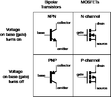
Among bipolar transistors, which are the older class of transistors, there are two types: NPN transistors, and PNP transistors. When you apply positive voltage to the base of an NPN transistor, it turns on the collector-emitter connection and allows current to flow from collector to emitter (Figure 6). The equivalent MOSFET is called an N-channel MOSFET. When you apply voltage to the base of a PNP transistor, by contrast, the collector-emitter connection turns off, and no current can flow from collector to emitter. The MOSFET equivalent is a P-channel MOSFET. One of the main differences between MOSFETS and bipolar transistors is that MOSFETS require negligible current on the base in order to activate. For the purposes of switching a load on and off, they are an excellent choice.
Figure 6. Chart comparing Bi-polar transistors and MOSFETS. NPN Transistors behave similarly to N-Channel MOSFETS. PNP Transistors are comparable to P-Channel MOSFETS
Among the bipolar transistors, there’s one type commonly used to switch high-current loads, the Darlington transistor. Darlington transistors are actually two transistors in one, combined with a diode that protects the transistors from damage in case the load’s current runs in reverse. In many of the labs on this site, you’ll see reference to one the TIP120 Darlington transistor.
Darlington transistors aren’t the only good transistors for high-current loads, though. You could use an N-Channel MOSFET with a protection diode in place of the darlington transistor. The IRF520 MOSFET is a good equivalent if you’re using a 5-volt microcontroller like the Uno. The FQP30N06L MOSFET works well for both 5V microcontrollers and 3.3V microcontrollers like the Nano 33 IoT.
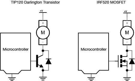
Figure 7 shows the basic circuit for using a transistor to control a high-current load. You connect a DC power source to one terminal of the load, then connect the second terminal of the load to the collector of the transistor (or drain, for a MOSFET) of the transistor. The emitter (or source) is then connected to ground, and the base (or gate) is connected to the output of your microcontroller. When you take the output pin of the microcontroller high, the voltage difference between the base (or gate) and the emitter (or source) allows current to flow through the load, through the collector (or drain) to the emitter (or source) and to ground.
Figure 7. Two similar microcontroller and motor schematics. The first schematic uses a Darlington Transistor. The second uses an N-Channel MOSFET.
Note how similar this schematic is to the relay schematic. The transistor here is serving the same function as the relay. However, it can switch much faster than the relay. In addition, because there are no mechanical parts, it will reliably function for more switching operations than the relay. However, current can only flow in one direction through a transistor. If the voltage on the collector (or drain) is lower than that on the emitter (or source), you can damage the transistor. The same is not true with a relay.
There are three differences between this transistor circuit and the relay circuit above. The first is that you’re using a motor as the load, rather than an incandescent light bulb. Because motors are inductive loads (they work because of induction; for more, see the DC motor notes), they can create a reverse voltage when spinning down after you turn them off. Because of this, the second difference is the protection diode in parallel with the transistor. The protection diode routes any reverse voltage around the transistor, thereby protecting it. Most transistors designed for controlling motors have a protection diode built-in. The TIP120, the IRF520, and the FQP30N06L all have built-in protection diodes. The third difference is that the microcontroller attached to the base (or gate) and the transistor’s emitter (or source) must have a common ground. If not, then the circuit will not work.
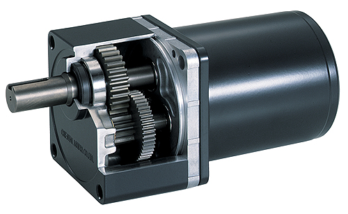
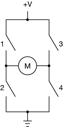
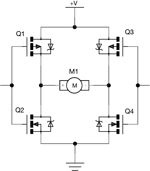
If you are switching DC motors, solenoids, or other high-current DC devices which create motion, it’s better to use a switching transistor than a relay. The ideal way to control a motor is with an H-bridge, which is an array of transistors that lets you control not only speed but also direction. There’s more on that in the motor control notes.
Power supply is a reference to the source of electrical power. Most electronic circuits require a DC power supply. Chances are you have one at home already, and can use it for physical computing projects.
The most common operating voltages for microcontrollers and digital processors are 5V and 3.3V. You can find power supplies in many voltages, but 5V and 12V are common. To convert 12V to 5V or 3.3V, you’d need a voltage regulator. The Breadboard Lab covers how to set that up.
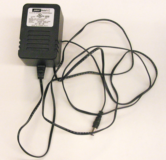
There are many different kinds of DC power supplies but this one shown in Figure 1 is most commonly used at ITP:
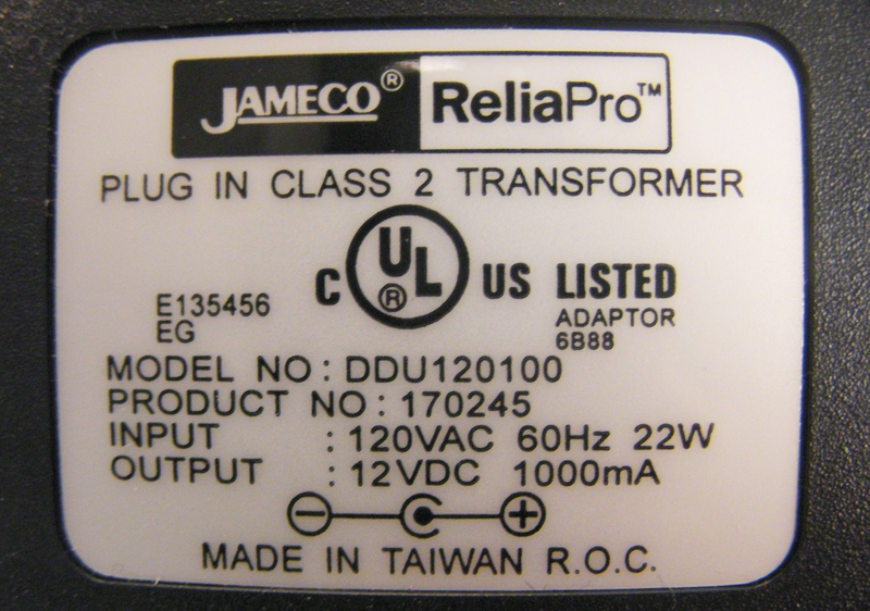
Figure 2. DC supply rating label. This is the back of the supply in Figure 1.
Most power supplies have a rating label that looks something like the one in Figure 2. Make sure you know the polarity of the plug so you don’t reverse polarity for your circuit and damage your components. The diagram in Figure 3 and Figure 4 showing positive tip polarity is on the left and negative tip polarity is on the right. The center positive drawing on the left indicates that the center (tip) of the output plug is positive (+) and the barrel of the output plug is negative (-).
Figure 3. Symbol for a center-positive power supply.
,
Figure 4. Symbol for a center-negative power supply.
Abbreviations
V : Volts A : Amperes W : Watts mA : miliAmperes VA : Volt Amperes VAC : Volts AC VDC : Volts DC DC : Direct Current AC : Alternating Current
Testing your power supply
It is always good practice to test a power supply before using it for the first time. The example below will show how to test a power supply with positive polarity. If you have a negative polarity power supply, then you will get a negative reading. You should then switch the position of the multimeter probes.
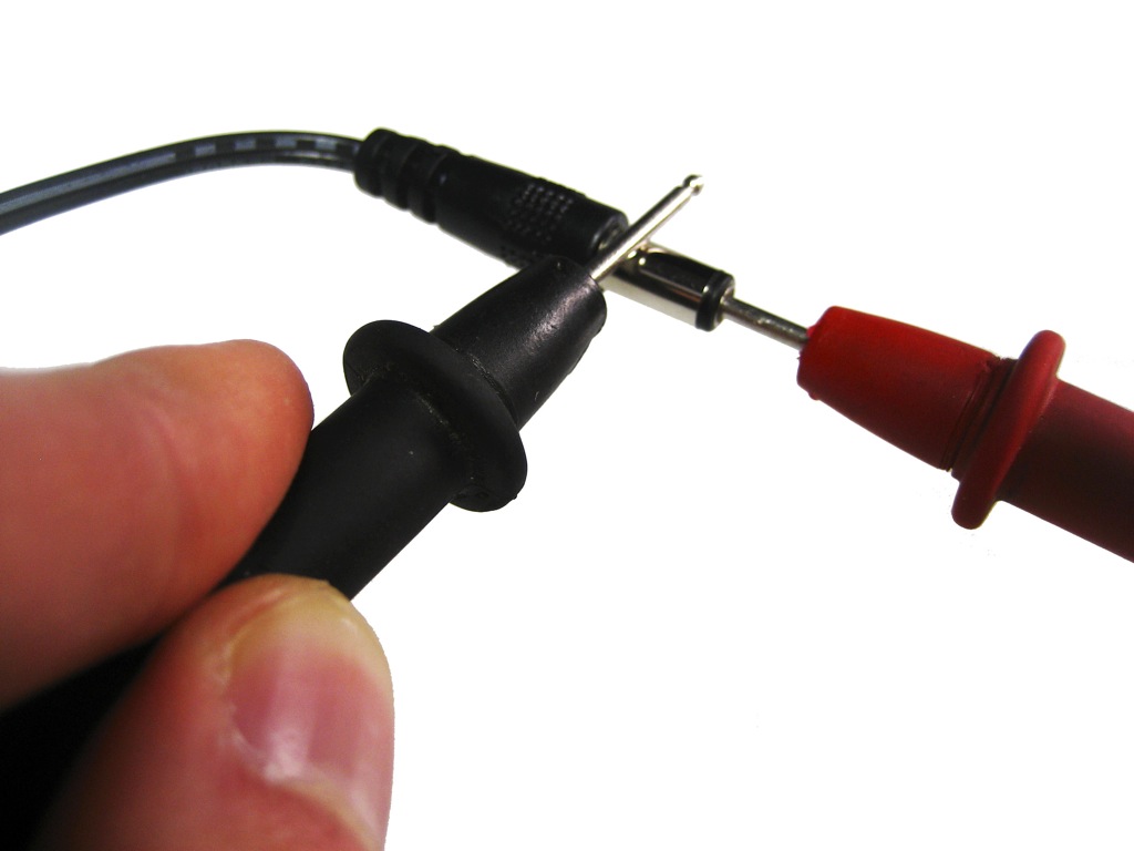
Figure 5. Red probe goes into the tip Black probe touches the barrel
Plug your power supply into an AC outlet.
Turn on your multimeter and set it to read DC voltage.
Take the red (positive) probe from your multimeter and stick it into the end of the power supply plug as shown in Figure 5.
Take the black (negative) probe from your multimeter and carefully touch it against the barrel of the plug without touching the tip or your red probe. If you make a connection, you will be creating a short circuit.
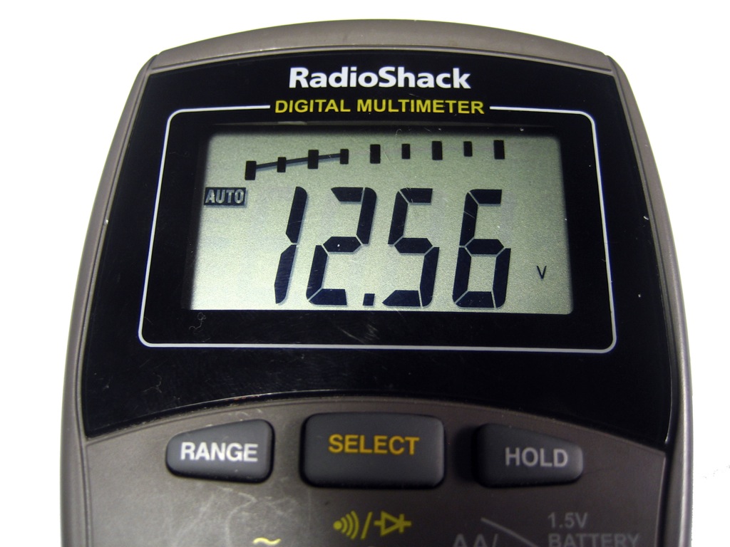
On your multimeter you should see a reading of the voltage coming from your power supply. If you are checking a 12V power supply and your multimeter shows “12.56V” everything is fine and dandy as shown in Figure 6. If you get a reading of “-12.56V” then your probes are attached in reverse. If this happens and you are positive you connected your probes correctly, double check the polarity on your power supply’s label and make sure the circuit you will be powering with this unit is designed to handle this polarity.
Figure 6. Multimeter displaying output DC voltage
If the voltage showing on your multimeter is more than half a volt or a volt off its rating, then you most likely have what is called an unregulated power supply. The 12V Jameco power supply we used in this example is a regulated one, so that is why the voltage we received was so close to the voltage it was rated for. Some 12V DC power supplies will actually read at 15-16V.
Unregulated power supplies run high on voltage when there is no load. When the supply starts to take a load, the current consumed will go up, and the voltage will drop. There are (more expensive) constant current supplies and constant voltage supplies, which will adjust their current or voltage when there is a change in the voltage or current, respectively. For more on this, here’s a decent explanation.
This is a reason why we use voltage regulators, and why most microcontroller modules have them built in. They’re designed to take a range of voltage and output a constant, lower voltage. In a sense, a voltage regulator is a very minimal constant voltage supply.
Powering an Arduino Project from a Mobile Phone Charger
Many people have old mobile phone chargers around the house, and wonder, “Can I use this for powering an Arduino project?” Generally, you can. Just get a USB cable with the appropriate connectors to connect the phone charger to your Arduino. Most phone chargers output 5V and a few hundred milliamps, which will power an Arduino, some sensors, and some LEDs. If you try to program your Arduino from the phone charger’s cable, though, you may be out of luck. Many phone chargers come with USB cables that contain only the power connections, not the data connections.
Matching A Power Supply to an Electronics Device
To determine whether a power supply is right for your project, you need to note the voltages that each component operates at, and the current they consume, and make sure your power supply can provide the right amount of power.
Imagine you’re making a project that includes an Arduino, a few LEDs, some pushbuttons, some potentiometers or other variable resistors, and perhaps a speaker. The Digital In and Out lab and the Analog In lab, and the Tone Output labs all describe projects that meet this description. All of the components other than the Arduino in this project are powered from the Arduino voltage output. None of the external components consume more than a few milliamps each. The whole circuit, Arduino included, will likely consume less than 200 milliamps of current. Here’s a breakdown, measured using an LED and a potentiometer:
Arduino Uno, no external components: 0.04A (40 mA)
Arduino Nano 33 IoT, no external components: 0.01A (10 mA)
LED: 4 mA
potentiometer connected as analog input: 0.29 mA
8-ohm speaker, playing a tone on the output pin: 0.5 mA
A phone charger, which supplies 5 volts and about 500 milliamps to the Arduino, would do the job fine. The Arduino Uno operates on 5 volts, and the Arduino Nano 33 IoT, which operates at 3.3 volts, has a built-in voltage regulator that will convert the 5V to 3.3V.
If you had a 12-volt supply like the one above, you could also use it for these projects. The Arduino Uno has a voltage in plug which matches it, and can take up to 15V. An on-board regulator converts the higher voltage input to 5V. The Nano 33 IoT has an on-board regulator that can accept up to 20V in its Vin pin (physical pin 15), so if you connected a DC power Jack and connected the ground of the 12-volt supply to the Arduino’s ground and the positive connection of the 12-volt supply to the Arduino’s Vin pin, your project would operate.
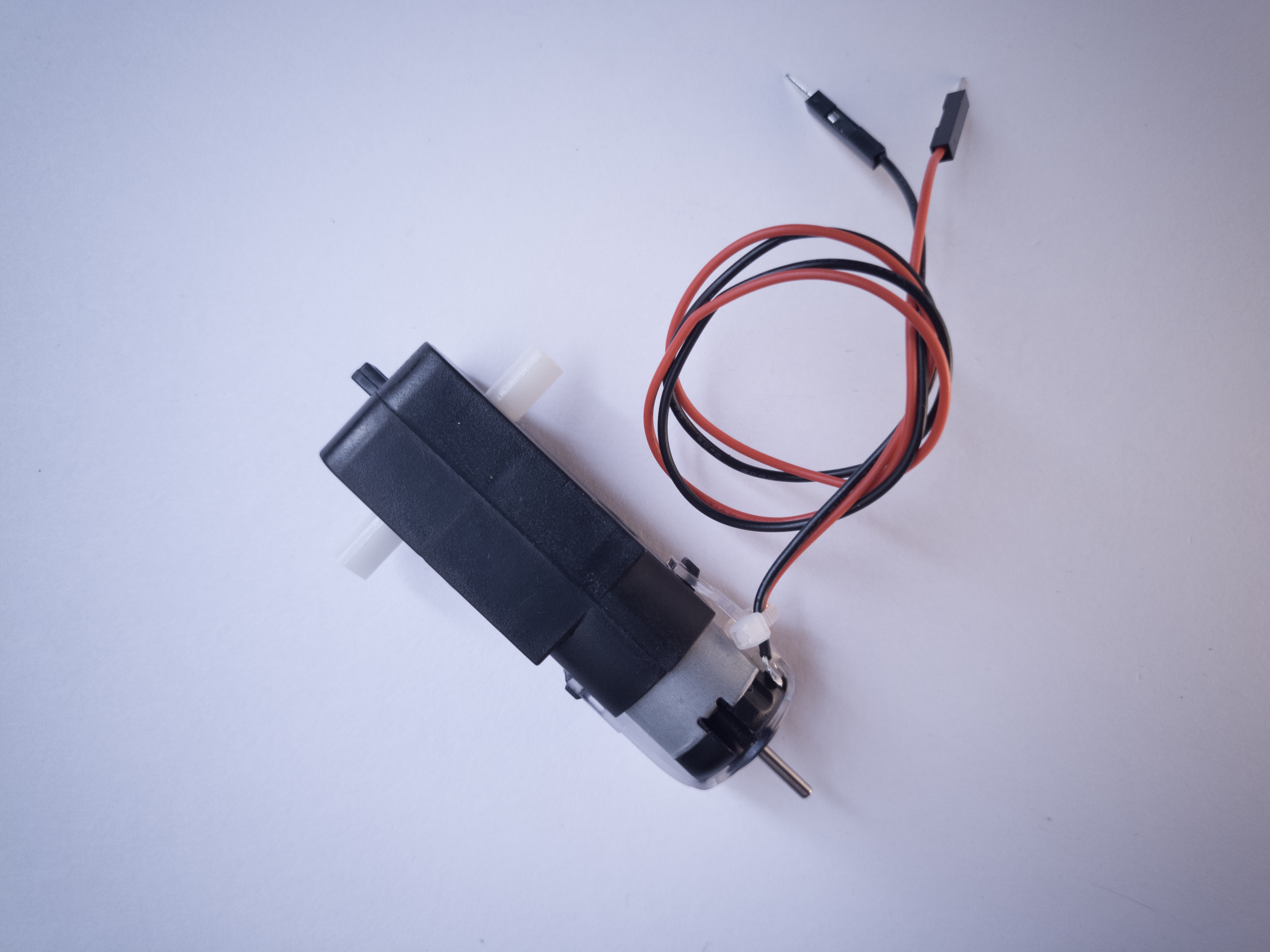
Arduino, Servomotor
If you’re controlling an RD servomotor from an Arduino as shown in the Servomotor lab, you need to consider the current a bit more. A servo like the Hitec HS-311 , which is popular in physical computing projects, operates at 4.8 – 6.0V, so it can get enough voltage from an Arduino’s voltage output. When it’s idle, it consumes about 160 mA with no load on it. It can consume up to 3-400 mA with a heavy load, however. It’s wise to plan your project for each component’s maximum current consumption, so a single servo and Arduino could consume up to 440 – 450 milliamps at 5 volts. That is almost the limit of what a laptop computer can supply via USB, and it’s the limit of some smaller phone chargers as well. If you were controlling multiple servos, you wouldn’t have enough current.
Arduino Uno, no external components: 0.04A (40 mA)
Arduino Nano 33 IoT, no external components: 0.01A (10 mA)
HS-311, heavy load: 400 mA
Arduino, DC Motor or Lights
When you start powering larger DC motors, DC lights, or other high-current loads, you have to calculate the voltage and current before you select a power supply. You generally work from the component that has the highest consumption and work from there.
For example, controlling an LED light bulb like this one would require a 12V DC power supply for the bulb. It consumes 11 watts of power, and watts = volts * amps, so it consumes about 917 milliamps of current at 12 volts. The transistor and Arduino that might control it could be powered via the same 12-volt power supply, and would consume the same amounts as in the examples above.
Motor projects and addressable LED projects often consume the most electrical energy and are the most complex to power. A typical addressable LED like a WS2812, aka NeoPixel LED, consumes between 60 and 80 mA of current at 5 volts. When you have a string of 60 of them, that’s 3.6 amps of current! These definitely can’t be powered from a typical DC wall supply. When you reach that level of complexity with a project, consult your components’ datasheets or your instructors for more guidance. The videos on electricity, current, and power are helpful on this subject as well.
Stepper motors are useful for when you need to rotate a full 360 degrees, but need to position your motor at a particular angle. What follows is a more detailed introduction to unipolar and bipolar stepper motors and how to control them from a microcontroller. In order to get the most out of these notes, you should know something about how electricity works, and you should know the basics of how a microcontroller works as well. You should also understand how transistors are used to control high-current loads. You should also understand how DC motors work.
As you learned in the introduction to motors, stepper motor is a motor controlled by a pair of electromagnetic coils. The center shaft has a series of magnets mounted on it, and the coils surrounding the shaft are alternately given current or not, creating magnetic fields which repulse or attract the magnets on the shaft, causing the motor to rotate.
There are two basic types of stepper motors, bipolar steppers and unipolar steppers. A bipolar is the simpler kind of stepper motor; it’s simply two coils, and has four wires. Depending on which coil you put power through, and which direction you send the power in, you step the motor one step forward or back. A unipolar stepper is slightly more complex. It also has two coils, but the centers of the coils are joined in a single junction. This effectively creates four coils, depending on how you put electrical energy through it.
A bipolar stepper motor usually has four wires coming out of it. It has two independent coils. Figure 1 shows a typical bipolar stepper with four wires. In the center is the motor’s shaft, which has a cog-like rotor on it. Each tooth of the cog is magnetized, and every cog’s magnetic polarity is opposite the one next to it.When you put voltage and current through one coil, it turns the central rotor a few degrees, because the magnets on the rotor are attracted to the magnetic field generated by the coil. When you turn that coil off and the other one on, the motor moves a few degrees more.
Figure 1. Wiring for a bipolar stepper motor.
To use a bipolar stepper, you need to know which wire is connected to which coil. You can determine this by measuring the resistance between pairs of wires. When you’ve got the leads of your meter connected to two wires on opposite coils, you should see infinite resistance, or no continuity. When your meter leads are on the same coil, you’ll be able to read the coil’s resistance. The two coils should have the same resistance.
Some bipolar steppers have a center connection on each coil. This allows for finer control over the motor, by treating each half coil as its own coil, as shown in Figure 2. These center connections can be joined to turn a 6-wire bipolar stepper into a unipolar stepper as well. Figure 3 shows the inside of a typical bipolar stepper motor.
Figure 2. a six-wire bipolar stepperFigure 3. Inside a Stepper motor. In this photograph, you can see the inside of a bipolar stepper. The two coils are actually divided into eight sub-coils for finer control. You can see the cog in the center as well. Each tooth on the cog is a tiny magnet.
Like other motors, stepper motors require more power than a microcontroller can give them, so you’ll need a separate power supply for them. Ideally you’ll know the voltage and load current from the manufacturer. If not, get a variable DC power supply, apply the minimum voltage (hopefully 3V or so), apply voltage across two wires of one coil (e.g. 1 to 2 or 3 to 4) and slowly raise the voltage until the motor is difficult to turn. It is possible to damage a motor this way, so don’t go too far. Typical voltages for a stepper might be 5V, 9V, 12V, 24V. Higher than 24V is less common for small steppers, and frankly, above that level it’s best not to guess.
Unipolar Stepper Motors
Unipolar steppers motor have five or six wires. The five-wire version has four coils which are all connected on one pole. Six-wire motors are actually bipolar steppers with two coils divided by center connections on each coil, as described above. The center connections of the coils are tied together as shown in Figure 4 and sometimes used as the power connection.
Figure 4. The wiring for unipolar stepper motors. The center wires for the two coils are tied together in a unipolar stepper.
Common Stepper Motor Types
There are two common families of stepper motor that you’ll encounter: NEMA motors and can-stack or tin-can steppers. The labs on this site can work with either. NEMA motors are designed according to a standard set by the US National Electrical Manufacturers Association. These are high-quality motors, and usually the more expensive that you’ll find. The number in a NEMA motor’s designation indicates the motor’s size. A NEMA-11 motor, for example, has a mounting face that’s 1.1 inches square; NEMA-23 is 23 step motor is 2.3 inches square and so forth. Electromate.com has a detailed explanation of NEMA motors if you ‘d like more detail.
Can-stack steppers are typically smaller and more cheaply made, mounted in a simple can, often with gears on top to increase torque and steps per revolution, and decrease speed. They’re often used in disk drives, motorized lens optics, and other industrial applications. The first number in the spec for these indicates the can’s diameter in millimeters. A 28BYJ-48 motor has a 28mm diameter can. A 24BYJ-48 has a 24mm can size, and so forth. Melissa Zheng has a good explanation of can-stack stepper motor specs.
Figure 5 shows a variety of NEMA-style steppers. Figure 6 shows a 28BYJ-48 can-stack stepper.
Figure 5. A range of NEMA stepper motors. Image from Pololu.comFigure 6. a can-stack stepper motor
Control of Stepper Motors
To control the stepper, apply voltage to each of the coils in a specific sequence. Both types of stepper motor can be controlled with a motor driver (related video). The sequence would go like this:
Step
Wire 1
Wire 2
Wire 3
Wire 4
1
high
low
high
low
2
low
high
high
low
3
low
high
low
high
4
high
low
low
high
Table 1. Sequential states of the voltage on the four control pins of a stepper motor.
To step the motor, you change the pins in the order shown in Table 1. With each step, the motor will move forward or backward one increment. Once you have the motor stepping in one direction, stepping in the other direction is a matter of doing the steps in reverse order.
It’s good practice when you wire a stepper up for the first time to write a program to step it slowly, one step at a time, using the steps above. That way you can see if you got the wiring right. If you did, the stepper should turn step by step in one direction. If you didn’t, it may step in unpredictable ways.
A stepper motor’s position is not absolute. You have to know where the motor started (usually measured with an external sensor) and how many degrees per step. Then you count the steps and multiply by that many degrees. So for examples, if you have a 1.8-degree stepper, and it’s turned 200 steps, then it’s turned 1.8 x 200 degrees, or 360 degrees, or one full revolution.
The circuits for controlling a unipolar stepper or a bipolar stepper are very similar. In both cases, you have four ends of coils that go to the four outputs of the driver. The difference is that for the unipolar, you also have a common center wire. That wire can be attached to the same motor voltage supply that feeds the driver, or it can be left disconnected. If you do the latter, you’re treating the unipolar motor as if it had two separate coils — in other words, as if it were a bipolar stepper.
H-bridge Stepper Drivers
There are a couple of different types of stepper motor drivers. The oldest use four transistors, treating each wire as if it were a motor itself. If you take wire 1 high and wire 2 low, coil turns one direction. Take wire 1 low, and wire 2 high, and the coil turns the other direction. The same principle applies to the other coil. This can be done with individual Darlington transistors or MOSFETs, or it can be done with a transistor array like the ULN2004.
The four-transistor approach is essentially an H-bridge, and you could use two H-bridges to control a stepper. The TB6612FNG dual motor driver that you saw in the H-bridge lab is a dual H-bridge designed for this purpose. You’ll see it in action in the H-bridge stepper motor lab. There is an older H-bridge that only operates on 5V, the L293D, which you will encounter from time to time. This driver does not work with the Arduino Nano 33 IoT and other 3.3V boards, but it’s common enough that it’s useful to know that it can be replaced with a TB6612FNG.
With an H-bridge style driver, you know what you’re getting: take the input 1 HIGH and input 2 LOW, and you create a voltage difference between outputs 1 and 2. It’s conceptually easy, but requires more thinking and planning when you are programming the stepper. Fortunately, there is a Stepper library for Arduino that simplifies this somewhat.
Step & Direction Stepper Drivers
More modern stepper drivers have just two control pins, one for step and one for direction. They also feature configuration pins that let you set the step pin to move the motor a full step, a half step, or less. This is called microstepping, and you can find stepper drivers that will work as low as 1/256th of a step. This allows finer control over the stepper motor.
Step & direction drivers simplify control of a stepper because they only require two signals from a microcontroller: take the direction pin high or low to turn the motor’s direction one way or the other. Then pulse the step pin. With each pulse, the motor should step in the direction set by the direction pin. You can run these kinds of steppers without a library. You’ll see these drivers in the step & direction stepper driver lab.
There are a number of step & direction motor drivers available. For example, ther STSPIN220 from ST microelectronics works in the 1.8-10V range. the A4988 handles motors in the 8-35V range. Trinamic’s drivers, also sold on breakout boards by Watterott as SilentStepStick boards, control a wide range of voltages and are designed to reduce noise. Allegro’s A4988 and Monolithic’s MP6500 and Texas Instruments’ DRV88xx line are also good driver lines to look at. Here’s a comparison chart for many of these lines, on breakout boards from Pololu. Table 2 is a summary of a few other step & direction drivers.
In picking a step & direction driver, the first questions to ask are:
Is my motor’s rated voltage in the driver’s Motor Voltage range?
Is my motor’s rated current less than the driver’s Max. Motor Current range?
Is my microcontroller’s operating voltage in the driver’s Control Voltage range?
Different kinds of computers are designed for different purposes. The computer at the heart of your laptop is optimized for different purposes than the one in your phone or the one in your mouse. The simplest computers are those that are designed to take inout from the physical world and control output devices in the physical world. These are called microcontrollers.
Most electronic devices you use today have a microcontroller at their core. Microcontrollers are optimized for control of physical input and output. They’re generally less computationally capable than the processors used in multimedia computers or servers, for example. They require less power than a those other processors, and they’re easier to interface with the physical world through input circuits called sensors and output circuits called actuators. They can communicate with other processors through various communication interfaces.
Computer, microcontroller, processor? Which is which?
You’ll hear these terms thrown around interchangeably here and in other writing about computers. Computer and processor are generic terms for the anything that can run a program, basically. Controller or microcontroller is usually reserved for a simple processor that does only one task, like listening to sensors. In explaining microcontrollers, we’ll distinguish them from personal computers or servers, which contain more powerful processors that can run an operating system.
Microcontrollers: Computers for the Physical World
When you’re building something that controls digital media from the physical world, it’s common to use microcontrollers to sense the user’s actions, then pass information about those actions to a multimedia processor like the one in your laptop. Keyboards and computer mice have microcontrollers inside that communicate with personal computers using the USB communications protocol.
Figure 1. Atmel Atmega328P chipFigure 2. Atmel Atmega328P chipFigure 3. SMD package of a microcontroller
Microcontrollers come in many different size packages as shown in Figure 1, Figure 2 and Figure 3.
Like any other computer, a microcontroller has to have input ports to detect action by a user, and output ports through which it expresses the results of its programs. The metal pins or contact points on a microcontroller are the inputs and outputs. Other devices, like light, heat, or motion sensors, motors, lights, our sound devices, are attached to these pins to allow the microcontroller to be sensitive to the world and to express itself. A microcontroller also requires power connections and communications connections, just like any other computer.
Figure 4 shows an Atmel (now owned by Microchip) microcontroller with its pins labelled. You can see which ones are general purpose input and output (GPIO), which ones are for power and communications, and which ones have specialty functions as well, the most common of which is analog input. For more on the typical functions of a microcontroller, see the Microcontroller Pin Functions page.
Figure 4. ATMEGA328 pin diagram
There are several different types of microcontrollers. The simplest have very little program memory, only one or two GPIO pins and no specialty functions. These might only cost a fraction of a dollar apiece in large quantities. Slightly more capable ones will have more memory, more GPIO pins and will include specialty functions as well, such as dedicated pins for particular communications protocols. The Atmega328 processor that’s at the heart of the Arduino Uno is one of these processors. The SAMD21 at the heart of the Nano 33 IoT is its more modern cousin. You can buy these processors for a few dollars apiece in quantity. More powerful than those are the controllers that have connections to interface to a display screen, like those in your mobile phone. These might cost several dollars, or tens of dollars. The more memory, processing power and input/output ports that a microcontroller has, the more expensive it tends to be.
When your device is complex enough to need an operating system, it might contain several controllers and processors. The controls for displays, power, and physical I/O are usually farmed out to microcontrollers, while the central processor runs the operating system, communicating with each lesser processor as needed.
The line between microcontrollers and operating system processors is getting blurry these days, so it helps to understand types of programs that different devices might run in order to understand the difference.
Programs for Microcontrollers and Other Processors
Programs for any processors fall into a few different classes: firmware, bootloaders, basic input-output systems, and operating systems. When you understand how they’re all related, you gain a better picture of how different classes of processors are related as well.
Microcontrollers generally run just one program as long as they are powered. That program is programmed onto the controller from a personal computer using a dedicated hardware programming device. The hardware programmer puts the program on the controller by shifting the instructions onto it one bit at a time, through a set of connections dedicated for this purpose. If you want to change the program, you have to use the programmer again. This is true of any processor, by the way: even the most powerful server or multimedia processor has to have a piece of firmware put on it with a hardware programmer at first.
Microcontrollers generally don’t run operating systems, but they often run bootloaders. A bootloader is a firmware program that lives in a part of the controller’s memory, and can re-program the rest of that memory. If you want to program a microcontroller directly from a personal computer without a separate hardware programmer, or from the internet, then you need a bootloader. Whenever your phone is upgrading its firmware, it’s doing it through a bootloader. Bootloaders allow a processor to accept new programs through more than just the dedicated programming port.
Any processor that runs an operating system will run a Basic Input-Output System, or BIOS as well. A BIOS may be loaded onto a processor using a bootloader. A BIOS runs before, or instead of, the operating system. It can control any display device attached to the processor, and any storage attached (such as a disk drive), and any input device attached as well.
Bootloaders and BIOSes are often called firmware because they’re loaded into the flash memory of the processor itself. See Table 1 for types of firmware. Other programs live on external storage devices like disk drives, and are loaded by the BIOS. These are what we usually think of software. Table 2 shows different kinds of software. When you change a processor’s firmware, you need to stop the firmware from running, upload the new firmware, and reset the processor for the changes to take effect. Similarly, when you change a microcontroller’s program, you stop the program, upload the new one, and reset the microcontroller.
An operating system is a program that manages other programs. The operating system schedules access to the processor to do the tasks that other programs need done, manages network and other forms of communications, communicates with a display processor, and much more.
Programs are compiled into the binary instructions that a processor can read using programs called compilers. A compiler is just one of the many applications that an operating system might run, however. The applications that an operating system runs also live on external storage devices like disk drives.
Firmware
Stored On
Detail
Single Program
Processor’s program memory
Is the only program running; must be loaded by hardware programmer
Bootloader
Processor’s program memory
Must be loaded by hardware programmer; Takes small amount of program memory; can load another program into the rest of program memory
BIOS
Processor’s program memory
Usually loaded by bootloader; can load operating system into RAM memory
Table 1. Types of firmware that are stored directly on a microprocessor
Software
Stored on
Details
Operating System
External mass storage
Runs other programs; loaded into RAM by BIOS; unloaded from RAM on reset
Drivers
External mass storage
Controls access to other processors, like disk drivers, keyboards, mice, screens, speakers, printers, etc. These are usually loaded into RAM on startup of the OS, and controlled by the OS, not the user.
Applications
External mass storage
Loaded into RAM by operating system and unloaded as needed
Table 2. Types of software on an operating system processor, and where they are stored.
Generally, the term microcontroller refers to firmware-only processor, and a processor that runs an operating system from external storage is called an embedded processor, or a central processor if it’s in a device with lots of other processors. For example, the Arduino is a microcontroller. The Raspberry Pi and BeagleBone Black are embedded processors. Your laptop are multi-processor devices running a central processor, a graphics processor, sound processor, and perhaps others.
Microcontroller Development Boards and Activity Boards
A processor, whether microcontroller or multimedia processor, can’t operate alone. It needs support components. For a microcontoller, you need at least a voltage regulator and usually an external clock called a crystal. You might also add circuitry to protect it in case it’s powered wrong, or in case the wrong voltage and current are plugged into the IO pins. You might include communications interfaces as well. This extra circuitry determines the base cost of a development board like the Arduino (Figure 5) or the Raspberry Pi (Figure 6).
Development boards usually include:
The processor itself
Power regulation circuitry
Hardware programmer connector
Communications interface circuitry
Basic indicator LEDs
Figure 5. An Arduino Uno.Figure 6. A Raspberry Pi
More advanced development boards might also include multiple communications interface circuits, including wireless interfaces; sensors already attached to some of the GPIO pins; a mass storage connector like an SD card; and video or audio circuitry, if the processor supports that. The more features a board offers, the more it costs.
A development board allows you to program the controller’s firmware and software, but an activity board may not. Activity boards contain a pre-programmed microcontroller and some sensors and actuators along with a communications interface and a communications protocol so that you can interface the board and its sensors and actuators with software running on your personal computer. Boards like the MaKey MaKey (Figure 7) or the PicoBoard (Figure 8, now retired) are activity boards. Activity boards generally can’t operate on their own without being connected to a personal computer, while development boards can.
Figure 7. A Makey Makey BoardFigure 8. A Sparkfun Picoboard
Do I Really Need A Development Board?
You can buy and program microcontrollers without a development board or activity board, but you’ll need some extras to do so. First, you’ll need to design your own support circuitry, at least a programmer interface and a power supply. You’ll need a hardware programmer as well, in most cases. And you’ll need to buy breakout boards or learn to make very small surface-mount circuits, since fewer and fewer microcontrollers come in the large dual inline package (DIP) that can plug into a solderless breadboard anymore. Generally, until you are very comfortable with electronics and circuit fabrication, it’s best to start with an activity board or a development board.
Toolchains and Development Environments
The two most common languages for microcontrollers are the assembly language of each particular processor, or the C programming language. More modern processors are starting to be developed in Python as well. A toolchain is the combination of compilers and linkers needed to convert the instructions you write into a binary file that the microcontroller can interpret as its instructions and the programmer software needed to upload that into the processor. Every manufacturer and processor family has its own assembly language (the beginning of the toolchain), but there’s a C compiler for almost every microcontroller on the market. Beyond that, a toolchain might include a compiler or firmware to convert a higher level language into the controller’s assembly language. If it’s a scripted language like Python, then the microcontroller’s firmware might include a Python interpreter that remains on the controller as your various scripts are swapped for one another in development.
A toolchain does the work of converting your code, but an integrated development environment (IDE) is needed to connect you, the programmer, to the toolchain. An IDE usually contains a text editor with user interface elements to send your text to the toolchain and upload the result to the processor. IDEs will also include a display to give you error messages about your code, and a monitor of some sort so that you can see what your code does when it’s running on the processor.
Things to consider when picking a microcontroller:
Here’s a guide to picking a microcontroller for this class. What follows are the economic considerations for picking a microcontroller more generally.
Costs
How much do I want to spend? The more features and flexibility, the higher the cost. But if it reduces the time taken between setting up and expressing yourself, it may be worth spending the extra money.
Time
How much work do I want to do?
An activity board or higher level development board will generally minimize the amount of work you do to build your interface to the world. Lower level dev boards or building your own boards will take more work before you have things working. Don’t go build your own boards unless you have to. Many good projects never get completed on time because the maker wanted to use their project as a way to learn how to make a circuit.
What programming languages/communications protocols/electronics do I already know?
All other things being equal, pick a system whose components you know something about.
What’s the knowledge base like?
Most microcontrollers have several websites and listserves dedicated to their use and programming. Quite often, the best ones are linked right off the manufacturer’s or distributor’s website. Check them out, look at the code samples and application notes. Read a few of the discussion threads. Do a few web searches for the microcontroller environment you’re considering. Is there a lot of collected knowledge available in a form you understand? This is a big factor to consider. Sometimes a particular processor may seem like the greatest thing in the world, but if nobody besides you is using it, you’ll find it much harder to learn.
Expandability/Compatibility
What other components is the microcontroller compatible with?
Can you add on modules to your microcontroller? For example, are their motor controllers compatible with it? Display controllers? Sensors or sensor modules? Often these modules are expensive but they just snap into place without you making any special circuitry. If your time is worth a great deal, then these modules are a good buy. Sometimes even if you know how to build it with a lower level controller, a higher level system is worth the cost because it saves building and maintenance time.
What do I have to connect to?
Are you connecting to a MIDI synthesizer? A DMX-512 lighting board? A desktop computer? The phone system? The Internet? Different microcontrollers will have different interface capabilities. Make sure you can connect everything together. Sometimes this requires some creative combinations of controllers if no one controller can speak to all the devices you want it to speak to.
Physical and Electrical Characteristics
How many inputs/outputs do I need? Every system has a certain number of ins and outs. If you can, decide how many things you want to sense or control before you pick your controller.
What kinds of inputs and outputs do I need? Do you need analog inputs and outputs, for sensing changing values, or do you only need digital ins and outs, for sensing whether something is on or off? Most of the embedded Linux boards (for example, the Raspberry Pi) do not have analog inputs, so be careful of that.
What kind of power is available to me? Does it need to be battery powered? Does it need to match the voltage of another device? Does it need to draw very little amperage?
How fast do I need to process data? Lower level processors will generally give you more speed.
How much memory do I need? If you’re planning some complex data processing or logging, you may need a microprocessor with lots memory, or the ability to interface with external memory.
How small does it need to be? A lower level controller generally lets you build your own circuitry, allowing you to reduce the size of the hardware you need.
The Economics of Microcontroller Development
So where does this leave you, the hobbyist or beginner with microcontrollers? What should you choose?
Using mid-level microcontrollers will cost you relatively little up front, in terms of peripherals. The various components you’ll need to make a typical project will run you about $75 – $100, including the controller. Starter kits are a good investment if you’ve never done it before, as they get you familiar with the basics. If you know your way around a circuit, you can start with just a development board. You can always keep the project intact and re-use the microcontroller for other projects. You’ll save yourself time not having to learn how a hardware programmer works, or which compiler to choose, or how to configure it. For the beginner seeking immediate gratification, mid-level is the way to go. The only downside is that if you want to build many more projects, you’ve got to buy another development board.
Using the controllers by themselves, on the other hand, is more of a hassle up front. You’ve got to know how to build the basic support and communications circuits, how to use a hardware programmer, and how to set up a toolchain. You’ll spend a lot of time early on cursing and wishing you’d bought a development board. The advantage comes a bit later on, once everything’s set up. You’ll eventually save money on development boards, and can make them in any shape you want. It gets better the longer you continue making microcontroller projects. So start with development or activity boards, and move up as your needs demand and knowledge can accommodate.
These notes are heavily indebted to Gordon McComb’s Robot Builder’s Bonanza, second edition, which includes some excellent chapters on motors and motor use.
When trying to move things with microcontrollers, you’re likely to use one of three kinds of motors: DC motors, RC servomotors, and stepper motors. Following is a brief introduction to these three. In order to get the most out of these notes, you should know something about how electricity works, and you should know the basics of how a microcontroller works as well. You should also understand how transistors are used to control high-current loads.
Motors convert electrical energy into mechanical energy so that you can move things in the physical world. They are based on the electrical principle of induction. When you put electric current through a wire, it generates a magnetic field around the wire as shown in Figure 1. The direction of the magnetic field is related to the direction of the electrical current. It’s often described as the right-hand rule. If you hold your right hand up and put your thumb perpendicular to your index finger, then put your middle finger perpendicular on the other axis, can see the directions of current flow (your index finger); magnetic force (your thumb); and the magnetic field line (your middle finger). The higher the current, the greater the magnetic field, and therefore the greater the attraction or repulsion.
Figure 1. The relationship between current, magnetic force, and magnetic field direction.
Similarly, if there’s a magnet near a wire, its field will interact with the wire’s magnetic field and generate a current in the wire. If you mount magnets on a spinning shaft surrounded by the wire, you have a motor. In Figure 2, the wire is arranged in two coils. As the magnets are alternately attracted to one coil and repulsed by the other, it spins from one to the other, and you get circular motion. Figure 2 illustrates the basic mechanism of a DC motor.
Figure 2. The basic mechanism of a DC motor.
All inductive loads (like motors, electromagnets, and solenoids) work on this same principle: induce a magnetic field by putting current through a wire, use it to attract or repulse a magnetic body. However, the principle works in reverse as well. When you spin a wire in an existing magnetic field, the field induces a current in the wire. So if you’ve got a motor spinning, and you turn it off, the fact that the motor’s coil is spinning in a magnetic field will generate a current in the wire while it’s spinning. You can test this by attaching an LED to the two leads of a DC motor and spinning the motor by hand. Spun in one direction, the LED will light. Spin in the other, the LED won’t light.
This generated current comes back in the reverse direction of the current flow you generated to run the motor. When the motor isn’t attached to another source of electricity, you’d call this a generator as in the LED experiment, because the motor is now generating voltage. When the motor is connected to another power source, it’s called back voltage, and it can cause damage to your electronics. Usually it’s stopped by putting a diode in parallel with your motor to route the back voltage through the diode.
Motor Characteristics
There are a few characteristics common to all motors that you should keep in mind when looking for motors:
Voltage
The rated voltage of a motor is the voltage at which it operates at peak efficiency. Most DC motors can be operated somewhat above or below their range, but it’s best to plan to operate them at their rated voltage. Dropping below rated voltage reduces the motor’s power, and operating above the rated voltage may burn the motor out. Plan on the motor’s top speed being at rated voltage, and slowest speed at no more than 50% less than the rated voltage.
Current
Motors draw current depending on the load they’re pulling. Usually more load means more current. Every motor has a stall current, which is the current it draws when it’s stopped by an opposing force. This stall current is generally much greater than the running current, or current that the motor draws under no load. Your power supply for a motor should be able to supply the stall current with extra amperage to spare. Motors will draw the stall current for a brief period of time when starting up, to overcome their inertia.
Speed
Motor speed is given in revolutions per minute (RPMs). At the rated voltage, your motor should be turning at the rated speed.
Torque
Torque is the measure of a motor’s turning force. It’s the force a motor can pull when the opposing force is attached to a shaft attached to its center rod. If the shaft sticks out a foot from the motor’s center, and the motor can pull one pound on that shaft, the motor’s torque is one foot-pound. Figure 3 illustrates this with a motor that supplies 1g*cm. Related video: Torque and Gearboxes
Figure 3. Torque illustrated. This motor can lift a 1 gram weight at a distance of 1 centimeter out from the center of rotation. Therefore, it can supply 1g*cm of torque.
Resistance
Often you’ll see a motor rated in ohms. This just gives you the resistance that the motor’s coil offers. Using Ohm’s Law (voltage = current x resistance), you can calculate the motor’s current draw if you know the rated voltage and the coil resistance.
Types of Motors
DC Motor
The DC Motor is the simplest of the motors discussed here. Figure 4 shows a photo of a small DC motor. It works on exactly the principle discussed above. There are two terminals, and when you apply direct current to one terminal and ground the other, the motor spins in one direction. When you apply current to the other terminal and ground the first terminal, the motor spins in the opposite direction. By switching the polarity of the terminals, you reverse the direction of the motor. By varying the current supplied to the motor, you vary the speed of the motor. Specific techniques for doing these tasks are discussed below. Related video: Power to a DC Motor
DC motors are usually very fast, often spinning at several thousand revolutions per minute (RPM). The DC motor in Figure 4 is common to many toy and hobby projects.
Figure 4. Small DC motor, 130 size
For more on DC motor control, see this lab for single-direction control, or this lab for controlling a motor in two directions with an H-Bridge.
Gearhead Motor
Gearhead motors are a subset of DC motors. Figure 7 is a drawing of a gearhead motor. They have a box on the top of the motors containing a series of gears that slow the rotational speed of the motor down and increase the torque. They are useful when you don’t need a lot of speed, but you do need power. They are controlled exactly the same as regular DC motors.
Figure 7. Gearhead motor with the gears shown. Image from designworldonline
In Figure 8, you can see a gearmotor that uses this size motor. You can see the full specifications at this link. Table 1 has a summary of the specs. You can see that the no-load current is 190mA and the stall current is 250mA. and the rated voltage is 6V. Using this information, you could work out that the coil resistance is probably between 24 and 32 ohms. You can also see that the no-load speed is 230RPM and the stall torque is 0.8 kg-cm. These are the values for the motor with the gearbox attached.
Figure 8. DC Gearmotor
Voltage (Nominal)
6VDC
No-Load Speed @ 6VDC
230RPM
No-Load Current @ 6VDC
190mA
Stall Current @ 6VDC
250mA
Stall Torque @ 6VDC
11.11 oz-in (0.8 kg-cm)
Gear Ratio
48:1
Table 1. Abbreviated specs on a gearmotor.
DC Motor Control
There are two easily controllable parameters of a DC motor, direction and speed. To control the direction, you reverse the direction of the voltage through the motor. To control the speed, you pulse width modulate it.
Direction
To control a DC motor from a microcontroller, you use switching arrangement known as an H-bridge, consisting of four switches with the motor in the center. Figure 9 is the schematic for a typical H-bridge:
Figure 9. An H-bridge, at its simplest, is composed of four switches with a load at the center of them.
When switches 1 and 4 are closed and 2 and 3 are open, voltage flows from the supply to 1 to the motor to 4 to ground. When 2 and 3 are closed and 1 and 4 are open, polarity is reversed, and voltage flows from the supply to 3 to the motor to 2 to ground. Related video: H-Bridge
An H-bridge can be built from transistors, so that a microcontroller can switch the motor, like this in Figure 10:
Figure 10. An H-bridge made of transistors.
This schematic uses MOSFETs, which are good for controlling motors. The top two transistors above are P-channel, meaning that they allow current to pass when the gate voltage is low rather than high. The bottom two are N-channel, so that the proper two transistors always switch together. When the left control pin is high, transistor 1 (labeled Q1) turns off because it’s a P-channel and Q2 turns on because it’s an N-channel. The same happens with Q3 and Q4. If you were using this circuit, you’d want to make sure that the control pins are always reversed; when one is high, the other is low. Related video: MOSFET Transistor
Although you can make your own H-bridges, it’s usually easier to use a controller manufactured specifically for the job. A pre-manufactured H-bridge chip will include diodes to protect the transistors from back voltage, sometimes a current sensing pin to sense the current the motor is drawing, and much more. There are many motor drivers available from various electronics suppliers. Look around to find one that suits your needs and price range.
Speed
A DC motor’s speed is proportional to the supplied voltage. If the voltage drops too far, the motor won’t get enough power to turn, but within a certain range, usually 50% of the rated voltage, the motor will run at varying speeds. The most effective way to adjust the speed is by using pulsewidth modulation. This means that you pulse the motor on and off at varying rates, to simulate a voltage. Related video: Why use PWM on DC Motors?
RC Servomotor
Servo motors are a variation on the gearhead motor coupled with a potentiometer to give feedback on the motor’s position. Figure 11 shows a photo of a small servomotor. The gears of the gearbox on a servo are attached to a potentiometer inside the case, and the pot is turned by the turning of the motor. The pot is connected to a capacitor in a resistor-capacitor circuit (R-C), and by pulsing this R-C circuit, you give the motor power to turn. When the motor turns, it changes the resistance of the R-C circuit, which in turn feeds the motor again. By pulsing the R-C circuit, you set the motor’s position in a range from 0 to 180 degrees. Related video: Meet the motors – servomotor
Figure 11. a small RC Servomotor
Servos have three wires to them, unlike most DC and gearhead motors, which have two. The first two in a servo are power and ground, and the third is a digital control line. This third line is used to set the position of a servo. Unlike other DC motors, you do not have to reverse the polarity of a servo’s power connections to reverse its direction.
Hobby servos, the kind most often used in small physical computing projects, usually take a pulse of between 1-2 ms every 18-20 ms. They rotate 0 to 180 degrees depending on the pulsewidth. A pulse of 1 ms will turn the motor to 0 degrees; 2 ms will turn it to 180 degrees. A servo needs to see a pulse every 18-20 ms even when it is not turning, to keep it in its current position, so once you’ve moved the motor to a new position, it’s essential to keep pulsing it with the same pulsewidth to keep it there.
Stepper motors are different than regular DC motors in that they don’t turn continuously, but move in a series of steps. A stepper motor is a motor that has multiple coils, not just one. By energizing each coil in sequence, you attract the shaft magnets to each coil in the sequence, and you can turn the motor in precise steps, rather than simply rotating continually. Figure 12 shows photos of stepper motors in varying sizes.
Figure 12. Stepper motors
This design allows for very precise control of the motor: by proper pulsing, it can be turned in very accurate steps of set degree increments (for example, two-degree increments, half-degree increments, etc.). They are used in printers, disk drives, and other devices where precise positioning of the motor is necessary. Steppers usually move much slower than DC motors, since there is an upper limit to how fast you can step them (5-600 pulses per second, typically. However, unlike DC motors, steppers often provide more torque at lower speeds. They can be very useful for moving a precise distance. Furthermore, stepper motors have very high torque when stopped, since the motor windings are holding the motor in place like a brake.
To control a stepper, you use stepper driver that will energize the coils in the right order to make the motor move forward. There are plenty of libraries and driver modules and ICs that simplify the process. What follows is a low-level explanation of how steppers work.
Stepper Motor Control
There are two types of stepper motors, called unipolar and bipolar. The difference is in their wiring. Unipolar steppers have all of their coils joined by a center wire. Bipolar steppers have two coils, which are not joined. Unipolar motors typically have five wires, while bipolars have four or six wires. Unipolar stepper motor’s wiring works as shown in Figure 13:
Figure 13. The wiring for unipolar stepper motors. The center wires for the two coils are tied together in a unipolar stepper.
The extra two wires in a 6-wire bipolar stepper allow you to use it as a 4-coil motor instead of a 2-coil, by using the center wire on each coil as a common supply or ground. In addition, you can turn a 6-wire bipolar into a 5-wire unipolar by joining the two center wires as shown in Figure 14:
Figure 14. Wiring for bipolar stepper motors.
To determine which wire is which, measure the resistance of the coils. In a bipolar motor, the two coils will have the same resistance, and they are not connected to each other. So if you see infinite resistance, you have two wires on separate coils. When you find two pairs that have the same resistance, you’ve found the two coils of your bipolar stepper. In a six-wire bipolar motor, the resistance between the outside wires of a coil will be twice what it is between the center wire and either outer wire. In a unipolar stepper, the resistance between the center wire and any of the other four will be the same, and the resistance between any two outer wires will be twice what it is from the center wire to any of the outer wires, as shown in Figure 15 and Figure 16:
Figure 15. Schematic drawing of a unipolar stepper motor. If the resistance between 5 and any of the others is X ohms, then the resistance between any of the other pairs (e.g. 2 to 4, 3 to 4, etc.) is 2X ohms.
Figure 16. Schematic drawing for two bipolar stepper motors. In both cases, if the resistance between the ends of either coils is X ohms, then the resistance between either end and the middle of a coil is 0.5X ohms.
Like other motors, the stepper requires more power than a microcontroller can give it, so you’ll need a separate power supply for it. Ideally you’ll know the voltage from the manufacturer, but if not, get a variable DC power supply, apply the minimum voltage that the supply can generate voltage across two wires of a coil (e.g. 1 to 2 or 3 to 4) and slowly raise the voltage until the motor is difficult to turn. It is possible to damage a motor this way, so don’t go too far. Typical voltages for a stepper might be 5V, 9V, 12V, 24V. Higher than 24V is less common, and frankly, above that it’s best not to guess. Related video: Connect 12V Power Supply
To power each coil, you supply voltage one side of the coil while grounding the other side. Typically, you drive a stepper motor with an H-bridge or an array of power transistors or MOSFETS.
To move the stepper, you apply voltage to each of the coils in a specific sequence. Typical phasing could go as shown in Table 2
Step
Wire 1
Wire 2
Wire 3
Wire 4
1
high
low
high
low
2
low
high
high
low
3
low
high
low
high
4
high
low
low
high
Table 2. Stepper motor wire stepping sequence
Once you have the motor stepping in one direction, stepping in the other direction is simply a matter of doing the steps in reverse order. Knowing the position is a matter of knowing how many degrees per step, and counting the steps and multiplying by that many degrees. So for examples, if you have a 2-degree stepper, and it’s turned 180 steps, then it’s turned 2 x 180 degrees, or 360 degrees, or one full revolution.
This tutorial explains how computer programs organize information in computer memory using variables. All computer programming languages use variables to manage memory, so it’s useful to understand this no matter what programming language or computer you’re using. Although the following was written with microcontrollers and physical computing applications in mind, it applies to programming in general.
The programming language examples below use a syntax based on the programming language C. That same syntax is used by many other languages, including Arduino (which is written in C), Java, Processing (which is written in Java), JavaScript, and others.
What Is Computer Memory, Anyway?
A computer’s memory is basically a matrix of switches, laid out in a regular grid, not unlike the switches you see on the back of a lot of electronic gear as shown in Figure 1:
Figure 1. DIP Switches
Each switch represents the smallest unit of memory, a bit. If the switch is on, the bit’s value is 1. If it’s off, the value is 0. Each bit has an address in the grid. We can envision a grid that represents that memory like this:
bit0
bit1
bit2
bit3
bit4
bit5
bit6
bit7
bit8
bit9
bit10
bit11
bit12
bit13
bit14
bit15
–
–
–
–
–
–
–
–
–
–
–
–
–
–
–
–
–
–
–
–
–
–
–
–
–
–
–
–
–
–
–
–
–
–
–
–
–
–
–
–
–
–
–
–
–
–
–
Table 1. All data that’s stored in computer memory is stored in these arrays of bits.
So if a bit can be only 0 or 1, how do we get values greater than 1?
When you count normally, you count in groups of ten. This is because you have ten fingers. So to represent two groups of ten, you write “20”, meaning “2 tens and 0 ones”. This counting system is called base ten, or decimal notation. Each digit place in base ten represents a power of ten: 100 is 102, 1000 is 103, etc.
Now, imagine you had only two fingers. You might count in groups of two. This is called base two, or binary notation. So two, for which you write “2” in base ten, would be “10” in base two, meaning one group of two and 0 ones. Each digit place in base two represents a power of two: 100 is 22, or 4 in base ten, 1000 is 23, or 8 in base ten, and so forth.
Any number you represent in decimal notation can be converted into binary notation by simply regrouping it in groups of two. Once you’ve got the number in binary form, you can store it in computer memory, letting each binary digit fill a bit of memory. So the number 238 in decimal notation would be 11101110 in binary notation. The bits in memory used to store 238 would look like this:
27 (128)
26 (64)
25 (32)
24 (16)
23 (8)
22 (4)
21 (2)
20 (1)
1
1
1
0
1
1
1
0
Table 2. The bits of the decimal value 238. 238 = 27 (128) + 26 (64) +25 (32) +23 (8) + 22 (4) + 21 (2)
Arranging Memory into Variable Space
Programming languages organize computer memory by breaking the grid of bits up into smaller chunks and labeling them with names. Those names are called variables, and they refer to a location in the computer’s memory. When you ask for the value of a variable, you’re asking what the states of the switches in that location in memory are.
If you think of your program as a set of instructions, then variables are the words that you use to describe what those instructions act upon.
For example:
” When the user has pushed the button two times… “
For this you need a variable called buttonPushed, and you need to check when it’s equal to 2:
if (buttonPushed == 2)
When you want to store a piece of something like the number of times a button’s been pushed in the computer’s memory, you give it a name and a data type, which states how much memory you intend to use. You usually give it an initial value as well. This is called declaring the variable, and it looks like this:
int sensorValue = 234;
byte buttonPushed = 15;
long timeSinceStart = 10324;
boolean isOpen = false;
Data Types
Every variable has a data type. The data type of a variable determines how much of the computer’s memory the variable will occupy. Different programming languages have different data types. The examples above use data types from the C programming language that Arduino uses.
The first one, int sensorValue, is an integer data type. Ints in C take up 16 bits (32 bits in the 32-bit boards like the Nano 33 IoT), so they can contain 216 different values (or 232). Ints can only contain integers, but they can be positive or negative, so the variable sensorValue above could range from -32,768 to 32,767. That’s a range from -215 to 215, with one bit used to store the plus or minus sign.
The second, buttonPushed, is a byte data type. Bytes take up 8 bits, and can therefore store 28 or 256 different values, from 0 to 255. Bytes in Arduino are unsigned, meaning that they can only be positive numbers.
The third, timeSinceStart is a long integer type, for storing very large values. In this instance, it might be storing the number of milliseconds since your program started, which can get big very quickly. Long ints are signed, and can range from -2,147,483,648 to 2,147,483,647. That’s 232 possible values.
The fourth, isOpen, is a boolean variable. Booleans can only true or false, and ideally take up just one bit in memory (though most programming languages use a whole byte for convenience).
0
0
0
0
0
0
0
0
1
1
1
0
1
0
1
0
0
0
0
0
1
1
1
1
0
0
0
0
0
0
0
0
0
0
0
0
0
0
0
0
0
0
1
0
1
0
0
0
0
1
0
1
0
1
0
0
0
–
–
–
–
–
–
–
Table 3. A number of variables stored in a processor’s memory as 1s and 0s.
When you declare a variable, the microcontroller picks the next available address and sets aside as many bits are needed for the data type you declare. If you declare a byte, for example, it sets aside 8 bits. An integer gets 16 bits. A string gets one byte (eight bits) for every character of the string, and a byte to end the string.
What About Fractional Numbers?
The variable types above are all for whole numbers, or integers. But how do you store a number like 3.1415 or 2.7828 or other fractional numbers? These are called floating-point numbers in the programming world, and they’re a special type of variable called a float. In Arduino, floats are actually 32-bit numbers, stored in 4 bytes of memory. A few of those bits are used to store the decimal point position.
Depending on the processor you are using, the data types might be different sizes. Table 4 shows the different sizes for the data types on the Uno, an 8-bit processor, and the Nano 22 IoT, a 32-bit processor.
Data Type
Uno
Nano 33 IoT
byte
1 byte
1 byte
int
2 bytes
4 bytes
float
4 bytes
4 bytes
char
1 byte
1 byte
long
4 bytes
4 bytes
short
2 bytes
2 bytes
double
4 bytes
8 bytes
bool
1 byte
1 byte
Table 4. The basic Arduino data types and their relative sizes on the Uno and Nano 33 IoT
Here’s a snippet of code to find out a given data type’s size on an Arduino:
Serial.print(sizeof(int));
Replace int above with byte, bool, double, float, long, or the data type whose size you want to know.
Choosing the Right Data Type
How do you know what data type to choose when declaring variables? It depends on two factors: what you’re going to use the variables for, and what functions you plan to use on them. First, consider how likely the numbers you might store are likely to be. For example, if you’re counting button pushes, you’re unlikely to get more than a few hundred in a few minutes, so an int or a byte might be fine. But for a number that might get large, like counting the number of milliseconds since some past event, the number could get very large, so you might need a long int.
Different built-in functions of a programming language will require different data types as parameters, so when you can, use data types that match the functions you plan to use. For example, if you were using a variable to store the results of Arduino’s millis() function, you should use a long int, because millis() returns that data type.
Doing Math With Variables
When you add, subtract, multiply, or divide with variables in a computer program, the results you get depend on the variable types you used. For example, if you ran the function below:
int voltage = 5;
int divider = 2;
int newVoltage = voltage / divider;
You might think that newVoltage = 2.5, right? Wrong. Because you used ints, the fractional part is gone, so the result would be 2. Here’s another:
After this, you’d expect that buttonPushes = 258, right? Wrong again! Because you used a byte, you can’t store a value larger than 255, so when the result is larger than that, the number rolls over to the lowest possible value again. The result would be 2.
Wait, what?
Look at it this way. The highest value you can store in a byte is 255. Therefore, if you try to store 256, it rolls over to 0. 257 rolls over to 1. And 258 rolls over to 2. So 254 + 4 in a byte variable yields 2. If you used an int instead of a byte, then you’d get the result you expect (258) because an int can hold values larger than 255.
Numeric Notation Systems
There are three notation systems used most commonly in programming languages to represent numbers: binary (base two), decimal (base ten), and hexadecimal (base sixteen). In hexadecimal notation, the letters A through F represent the decimal numbers 10 through 15. Furthermore, there is a system of notation called ASCII, which stands for American Standard Code for Information Interchange, which represents most alphanumeric characters from the romanized alphabet as number values. More on ASCII can be found in the pages on serial communication. For more, see this online table representing the decimal numbers 0 to 255 in decimal, binary, hexadecimal, and ASCII. While you can work mostly in decimal notation, there are times when it’s more convenient to represent numbers in ms other than base 10.
Table 5 shows a few number values in the different bases, and the different notation forms:
Decimal value
Hexadecimal
Binary
3
0x03
0b11
12
0x0C
0b1100
45
0x2D
0b101101
234
0xEA
0b11101010
1000
0x3E8
0b1111101000
Table 5. A few number values in base 10, and their equivalent values in binary (base 2)
Because the values are all bits in the computer’s memory, you can use all of these notation systems interchangeably. Here are a few examples:
if (colorValue == 0xFF); // check to see if the color value is 255

// add 5 to 0x90. Result will be 0x95:
int channelNumber = 5;
int midiCommand = 0x90 + channelNumber;
Variable scope
Variables are local to a particular function in your code if they are declared in that function. Local variables can’t be used by functions outside the one that declares them, and the memory space allotted to them is released when the function ends. Variables are global when they are declared at the beginning of a program, outside all functions. Global variables are accessible to all functions in a the program, and their value is maintained for the duration of the program. Usually you use global variables for values that will need to be kept in memory for future use by other functions, and local variables when you know the value won’t be used outside that function. In general, it’s better to default to local variables when you can, to manage memory more efficiently. Here’s a typical example:
int oldButtonPush = 0;  // global variable

void setup() {
   Serial.begin(9600);
}

void loop() {
   int buttonPush = digitalRead(3); // local variable
   if (buttonPush != lastButtonPush) {
      // the button changed. Do something here
      // then store the current button push state
      // in the global variable for the next time
      // through the loop:
   oldButtonPush = buttonPush;
   }
}
In this example, the variable buttonPush is local to the loop function. You couldn’t read it in the setup, or any other function. The variable oldButtonPush, on the other hand, is global, and can be read by any function. In the example above, the local variable is used to read the latest state of a digital input, and then later, the value is put into the global variable so that you can get a new reading and compare it to the old one.
Constants
In addition to variables, every programming language also includes constants, which are simply variables that don’t change. They’re a useful way to label and change numbers that get used repeatedly within your program. For example, imagine you’re writing a program that runs a servo motor. Servo motors have a minimum and maximum pulse width that doesn’t change, although each servo’s minimum and maximum might be somewhat different. Rather than change every occurrence of the minimum and maximum numbers in the program, we make them constants, so we only have to change the number in one place.
You don’t have to use constants in your programs, but they’re handy to know about, and you will encounter them in other people’s programs.
In C and therefore in Arduino, there are two ways you can declare constants. You can use the const keyword, like so:
const int LEDpin = 3;
const int sensorMax = 253;
Or you can use define:
#define LEDPin 3
#define sensorMax 253
Defines are always preceded by a #, and are don’t have a semicolon at the end of the line. Defines always come at the beginning of the program. They actually work a bit like aliases. What happens is that you define a number as a name, and before compiling, the compiler checks for all occurrences of that name in the program and replaces it with the number. This way, defines don’t take up any memory, but you get all the convenience of a named constant. There are several defines in the libraries of the Arduino core libraries, so it’s preferable to use const instead of #define for constants.