Lab: Two-Way (Duplex) Serial Communication Using An Arduino and the p5.webserial Library

Introduction

In the Introduction to Asynchronous Serial Communication lab, you learned about various methods for managing the communications between computers via asynchronous serial communication. These included formatting your data as ASCII-encoded strings or raw serial bytes and managing the flow of data using handshaking. In the P5.js WebSerial Input Lab, you sent data from one sensor to a personal computer. In this lab, you’ll send data from multiple sensors to a program in p5.js. using the  p5.WebSerial library. You’ll use the data from the sensors to create a pointing-and-selecting device (i.e. a mouse).

What You Should Know

To get the most out of this tutorial, you should know what a microcontroller is and how to program them. You should also understand asynchronous serial communication between microcontrollers and personal computers. You should also understand the basics of P5.js. It would also help to go through the following labs first:

These videos might help in understanding this lab as well:

Things You’ll Need

For this lab, you’ll need the hardware below, and you’ll need the same software setup as the WebSerial Input to P5.js lab: You’ll create a p5.js sketch. You’ll also use the p5.WebSerial library. You can use the p5.js web editor or your favorite text editor for this (the Visual Studio Code editor works well).

Figures 1-5 below are the parts you’ll need for this exercise. Click on any image for a larger view.

Photo of an Arduino Nano 33 IoT module. The USB connector is at the top of the image, and the physical pins are numbered in a U-shape from top left to bottom left, then from bottom right to top right.
Figure 1. Microcontroller. Shown here is an Arduino Nano 33 IoT
Photo of flexible jumper wires
Figure 2. Jumper wires.  You can also use pre-cut solid-core jumper wires.
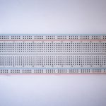
Photo of a solderless breadboard
Figure 3. A solderless breadboard
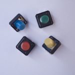
Photo of four breadboard-mounted pushbuttons
Figure 4. A pushbutton
Photo of two potentiometers
Figure 5. two potentiometers. You can use any two analog sensors in place of these if you prefer.

Connect the Sensors

For this exercise, you’re going to need two analog inputs to your microcontroller, and one digital input. It doesn’t matter what they are, so use something that’s easy for you to set up. The photos and schematic in this lab show potentiometers and a pushbutton. You don’t have to use these, though. Any three sensor inputs will do the job. If you’re looking for options, consider:
Photo of a breadboard-mountable joystick, This component is mounted on a printed circuit board that's about 4cm on each side. The joystick itself is about 6cm tall, controllable by a thumb. There are five pins on one side of the PCB for mounting on the breadboard.
Figure 6. A joystick, which consists of two potentiometers and a pushbutton
Photo of a rotary encoder
Figure 7. Rotary encoders, which include a built-in pushbutton
Photo of the IMU sensor on teh Nano 33 IoT. It's the small rectangular chip above and to the left of the main processor.
Figure 8. The built-in accelerometer on the Arduino Nano 33 IoT, which measures acceleration on three axes

As long as you have three sensors that will output changing readings, you can follow this lab.

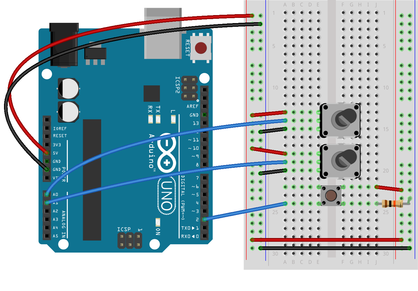
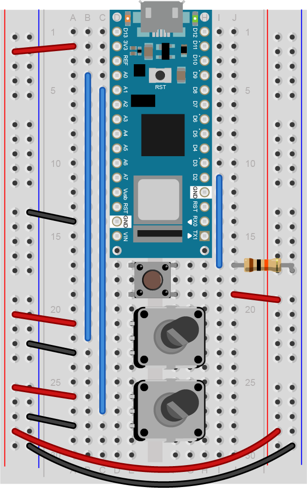
Connect the two analog sensors to analog pins 0 and 1 like you did in the analog input to Arduino lab. Connect a pushbutton to digital pin 2 like you did in the digital input and output with Arduino lab.

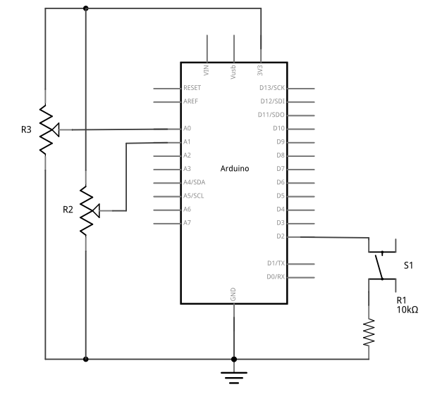
Schematic view of an Arduino attached to two potentiometers and a pushbutton. The potentiometers' center pins are connected to the Arduino's A0 and A1 inputs, respectively.
Figure 9. Schematic view of an Arduino attached to two potentiometers and a pushbutton. The potentiometers’ center pins are connected to the Arduino’s A0 and A1 inputs, respectively. Their left pins are connected to the voltage bus, and the right pins are connected to the ground bus, respectively. The pushbutton is connected from the Arduino’s voltage output to pin D2. a 10-kilohm connects the junction of the switch and pin D2 to ground.
Breadboard view of an Arduino Uno attached to two potentiometers and a pushbutton.
Figure 10. Breadboard view of an Arduino Uno attached to two potentiometers and a pushbutton. The potentiometers’ center pins are connected to the Arduino’s A0 and A1 inputs, respectively. Their left pins are connected to the voltage bus, and the right pins are connected to the ground bus, respectively. The pushbutton is connected from the Arduino’s voltage output to pin D2. a 10-kilohm connects the junction of the switch and pin D2 to ground.

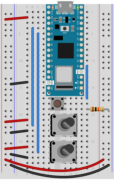
Breadboard view of an Arduino Nano attached to two potentiometers and a pushbutton
Figure 11. Breadboard view of an Arduino Nano attached to two potentiometers and a pushbutton. The potentiometers’ center pins are connected to the Arduino’s A0 and A1 inputs, respectively. Their left pins are connected to the voltage bus, and the right pins are connected to the ground bus, respectively. The pushbutton is connected from the Arduino’s voltage output to pin D2. a 10-kilohm connects the junction of the switch and pin D2 to ground.

(Diagrams made with Fritzing, a circuit design program)


Sending Multiple Serial Data using Punctuation

You’re going to program the microcontroller to read the pushbutton and two analog sensors just like you did in the Intro to Serial Communications Lab. When you have to send multiple data items, you need a way to separate them. If you’re sending them as ASCII-encoded strings, it’s simple: you can just put non-numeric punctuation bytes between them (like a comma or a space) and a unique termination punctuation at the end (like a newline and/or carriage return).

This program will send the two analog sensor values and then the pushbutton. All three will be ASCII-encoded numeric strings, separated by commas. The whole line of sensor values will be terminated by carriage return (\r, ASCII 13) and newline (\n, ASCII 10).

const int buttonPin = 2;      // digital input

void setup() {
  // configure the serial connection:
  Serial.begin(9600);
  // configure the digital input:
  pinMode(buttonPin, INPUT);
}

void loop() {
  // read the first analog sensor:
  int sensorValue = analogRead(A0);
  // print the results:
  Serial.print(sensorValue);
  Serial.print(",");

  // read the second analog sensor:
  sensorValue = analogRead(A1);
  // print the results:
  Serial.print(sensorValue);
  Serial.print(",");

  // read the button:
  sensorValue = digitalRead(buttonPin);
  // print the results:
  Serial.println(sensorValue);
}

When you run this and output it to the Serial Monitor, you should see something like this:

348,363,1
344,362,1
345,363,1
344,375,0
365,374,0
358,369,0
355,369,0
352,373,0
356,373,0

Turn the potentiometers (or tweak the analog sensors) and push the button. Now you’ve got a data format: three sensors, comma-separated, terminated by carriage return and newline. This means that you already have an algorithm for how you’re going to program p5.js to read the serial input. You’ll see that algorithm in the next section.

Receive the data in P5.js

Now write a P5.js sketch that reads the data as formatted by the Arduino program above. The setup will be the same as it was in the Serial Input to p5.js using WebSerial lab. The checklist from that lab lays out all the important parts you need.

The sketch you’re going to write will:

  • Read the incoming serial data into a string until a carriage return and newline appear
  • split the string into substrings on the commas
  • convert the substrings into numbers
  • assign the numbers to variables to change your programNow that you’ve got a plan, put it into action.

Make a P5.js sketch. If you’re using the p5.js web editor, make a new sketch. Click the Sketch Files tab, and then choose the index.html file. Edit the head of the document as you did for the other p5.webserial labs. It should look like this:

<script src="https://cdnjs.cloudflare.com/ajax/libs/p5.js/1.4.0/p5.js"></script>
	
<script src="https://unpkg.com/p5-webserial@0.1.1/build/p5.webserial.js"></script>

The setup of your sketch will initialize the P5.webserial library and define your callback functions for serial events as you did in other sketches. It should look like this:

// variable to hold an instance of the p5.webserial library:
const serial = new p5.WebSerial();

// HTML button object:
let portButton;
let inData;                      // for incoming serial data
let outData;                     // for outgoing data

function setup() {
  createCanvas(400, 300);          // make the canvas
  // check to see if serial is available:
  if (!navigator.serial) {
    alert("WebSerial is not supported in this browser. Try Chrome or MS Edge.");
  }
  // if serial is available, add connect/disconnect listeners:
  navigator.serial.addEventListener("connect", portConnect);
  navigator.serial.addEventListener("disconnect", portDisconnect);
  // check for any ports that are available:
  serial.getPorts();
  // if there's no port chosen, choose one:
  serial.on("noport", makePortButton);
  // open whatever port is available:
  serial.on("portavailable", openPort);
  // handle serial errors:
  serial.on("requesterror", portError);
  // handle any incoming serial data:
  serial.on("data", serialEvent);
  serial.on("close", makePortButton);
}
function draw() {

}

// if there's no port selected, 
// make a port select button appear:
function makePortButton() {
  // create and position a port chooser button:
  portButton = createButton('choose port');
  portButton.position(10, 10);
  // give the port button a mousepressed handler:
  portButton.mousePressed(choosePort);
}

// make the port selector window appear:
function choosePort() {
  serial.requestPort();
}

// open the selected port, and make the port 
// button invisible:
function openPort() {
  // wait for the serial.open promise to return,
  // then call the initiateSerial function
  serial.open().then(initiateSerial);

  // once the port opens, let the user know:
  function initiateSerial() {
    console.log("port open");
  }
  // hide the port button once a port is chosen:
  if (portButton) portButton.hide();
}

// read any incoming data as a byte:
function serialEvent() {
 
}

// pop up an alert if there's a port error:
function portError(err) {
  alert("Serial port error: " + err);
}

// try to connect if a new serial port 
// gets added (i.e. plugged in via USB):
function portConnect() {
  console.log("port connected");
  serial.getPorts();
}

// if a port is disconnected:
function portDisconnect() {
  serial.close();
  console.log("port disconnected");
}

Change the serialEvent() function to read the incoming serial data as a string until it encounters a carriage return and newline (“\r\n”). Then check to see that the resulting string has a length greater than 0 bytes. If it does, use the split() function to split it in to an array of strings. If the resulting array is at least three elements long, you have your three sensor readings. The first reading is the first analog sensor, and can be mapped to the horizontal movement using the locH variable. The second is the second analog sensor and can be mapped to the locV variable. The third is the button. When it’s 0, set the circleColor variable equal to 255 and when it’s 1, set the variable to 0. Here’s how:

function serialEvent() {
  // read a string from the serial port
  // until you get carriage return and newline:
  var inString = serial.readStringUntil("\r\n");
  //check to see that there's actually a string there:
  if (inString) {
    // split the string on the commas:
    var sensors = split(inString, ",");
    if (sensors.length > 2) {
      // if there are three elements
      // element 0 is the locH:
      locH = map(sensors[0], 0, 1023, 0, width);
      // element 1 is the locV:
      locV = map(sensors[1], 0, 1023, 0, height);
      // element 2 is the button:
      circleColor = 255 - sensors[2] * 255;
    }
  }
}

Note the mappings of sensors[0] and sensors[1]. If you’re not using potentiometers as the first two inputs on your Arduino, then you should use the input mappings for your sensors instead of 0 and 1023. If your analog values are greater than the width of the sketch or the height, the circle will be offscreen, which is why you have to map your sensor range to the screen size.

Program the draw() function to draw a circle that’s dependent on three global variables, locH, locV, and circleColor. Add these three globals to the top of the program:

// variables for the circle to be drawn:
let locH, locV;
let circleColor = 255;

Finally, here is the draw function:

function draw() {
  background(0);               // black background
  fill(circleColor);           // fill depends on the button
  ellipse(locH, locV, 50, 50); // draw the circle
}

If you run this, you should see the circle moving onscreen whenever you change your sensors. When you press the pushbutton, the circle will disappear. Okay, it’s not exactly a  mouse, but you are controlling an animation from a device that you built.

Flow Control: Call and Response (Handshaking)

You’ve seen now that by coming up with a serial format (called a protocol), you can write the algorithm for receiving it even before you see any data. You can send multiple pieces of data this way, as long as you format it consistently.

Sometimes you can run into a problem when the sender sends faster than the receiver can read. When this happens, the receiver program slows down as the serial buffer fills up. You can manage this by implementing some form of flow control. The simplest way do to this is using a call-and-response method, where the sending program only sends when it’s told to do so, and the receiving program has to request new data every time it finishes reading what it’s got.

You can add handshaking to the code above fairly simply. Modify the Arduino code as follows. First, add a a new block of code in the setup() This block sends out a message until it gets a byte of data from the remote computer:

void setup() {
  Serial.begin(9600);
  while (Serial.available() <= 0) {
    Serial.println("hello"); // send a starting message
    delay(300);              // wait 1/3 second
  }
}

Now, modify the loop() by adding an if() statement to look for incoming serial data and read it.

void loop() {
  if (Serial.available() > 0) {
    // read the incoming byte:
    int inByte = Serial.read();
    // read the sensor:
    int sensorValue = analogRead(A0);
    // print the results:
    Serial.print(sensorValue);
    Serial.print(",");

    // read the sensor:
    sensorValue = analogRead(A1);
    // print the results:
    Serial.print(sensorValue);
    Serial.print(",");

    // read the sensor:
    sensorValue = digitalRead(buttonPin);
    // print the results:
    Serial.println(sensorValue);
  }
}

The rest of the sketch remains the same. When you run this and open the serial monitor, you’ll see:

hello
hello
hello
hello

Type any character in the output box and click Send. You’ll get a string of sensor values at the end of your hellos:

510,497,0

Type another character and click Send. It doesn’t matter what character you send, but the loop will always wait for an incoming byte before sending a new set of sensor values. When you write a program to receive this format, it just has to behave the same way you did:

  • Open the serial port
  • Wait for a hello
  • Send a byte to request data
  • Begin loop:
  • Wait for one set of data
  • Send a byte to request new data
  • end loop

Next, modify the P5.js sketch.  Most of the changes are in the serialEvent() function. The initial “hello” messages will trigger this function, so when you get a “hello” or any other string, you need to send a byte back so that the Arduino has a byte available to read. Here’s the new serialEvent():

function serialEvent() {
  // read a string from the serial port
  // until you get carriage return and newline:
  var inString = serial.readStringUntil("\r\n");
  //check to see that there's actually a string there:
  if (inString) {
    if (inString !== "hello") {
      // if you get hello, ignore it
      // split the string on the commas:
      var sensors = split(inString, ",");
      if (sensors.length > 2) {
        // if there are three elements
        // element 0 is the locH:
        locH = map(sensors[0], 0, 1023, 0, width);
        // element 1 is the locV:
        locV = map(sensors[1], 0, 1023, 0, height);
        // element 2 is the button:
        circleColor = 255 - sensors[2] * 255;
        // send a byte back to prompt for more data:
        serial.print('x');
      }
    }
  }
}

You also need to add a line to the initiateSerial() function (which is inside the openPort() function) like so:

 function initiateSerial() {
    console.log("port open");
    // send a byte to start the microcontroller sending:
    serial.print("x");
  }

The reason for this is that if your Arduino is still in the setup() waiting for a byte to arrive, then it needs p5.js to send something when the port is opened. If the Arduino has already broken out of the loop (let’s say you opened the Serial monitor to check), then it is waiting for a byte from p5.js to send the next block of code. Whether it’s in the initiateSerial() function or at the end of the serialEvent() function, by sending a byte when you know the port has just been opened in p5.js, you force the Arduino to send you new data.

That’s it. Your sketch should still run just as it did before, though the serial communication is managed better now, because Arduino’s only sending when P5.js is ready to receive.

You can see the sketch running on GitHub at this link. You can see the source files for copying into the p5.js editor at this link.

Advantages of Raw Binary vs. ASCII

All the examples shown here sent the sensor values as ASCII-encoded strings. As mentioned above, that means you sent three bytes to send a three-digit value. If that same value was less than 255, you could send it in one raw binary byte. So ASCII is definitely less efficient. However, it’s more readable for debugging purposes, and if the receiving program is well-suited to convert strings to numbers, then ASCII is a good way to go. If the receiver’s not so good at converting strings to numbers (for example, it’s more challenging to read a multiple byte string in Arduino than in Processing) then you may want to send your data as binary values.

Advantages of Punctuation or Call-and-Response

The punctuation method for sending multiple serial values may seem simpler, but it has its limitations. You can’t easily use it to send binary values, because you need to have a byte with a unique value for the punctuation. In the example above, you’re using the value 10 (ASCII newline) as punctuation, so if you were sending your sensor values as raw bytes, you’d be in trouble when the sensor’s value is 10. The receiver would interpret the 10 as punctuation, not as a sensor value. In contrast, call-and-response can be used whether you’re sending data as raw binary values or as ASCII-encoded values.

Sometimes the receiver reads serial data slower than the sender sends it. For example, if you have a program that does a lot of graphic work, it may only read serial data every few milliseconds. The serial buffer will get full in that case, you’ll notice a lag in response time. This is when it’s good to switch to a call-and-response method.

Build an Application of Your Own

You just duplicated the basic functionality of a mouse; that is, a device with two analog sensors that affect X and Y, and a digital sensor (mouse button). What applications can you think of that could use a better physical interface for a mouse? A video editor that scrubs forward and back when you tilt a wand? An action game that reacts to how hard you hit a punching bag? An instructional presentation that speeds up if you shift in your chair too much? A music program driven by a custom musical instrument that you design?

Create a prototype in Arduino and P5.js, Node.js, Processing, or whatever programming environment you choose. Come up with a physical interface that makes it clear what actions map to what movements and actions. Figure out which actions can and should be possible at the same time. Present a working software and hardware model of your idea.

Lab: Serial Output From p5.js Using the p5.webserial Library

In this lab you’ll learn how to send data from p5.js to a microcontroller using asynchronous serial communication.

Overview

When you use the p5.webserial library for P5.js, it uses the W3C’s WebSerial API to allow your browser to communicate with serial ports on your computer. This lab shows you how to use P5 to control a microcontroller using asynchronous serial communication. WebSerial is currently only available in the Chrome and Chromium browsers and the Microsoft Edge browser, so make sure you’re using one of those to do this lab.

To get the most out of this tutorial, you should know what a microcontroller is and how to program them. You should also understand asynchronous serial communication between microcontrollers and personal computers. You should also understand the basics of P5.js, and should have tried the WebSerial Input to P5.js lab.

Things You’ll Need

For this lab, you’ll need the hardware below,

For this lab, you’ll need the hardware below, and you’ll need the same software setup as the WebSerial Input to P5.js lab: You’ll create a p5.js sketch. You’ll also use the p5.WebSerial library. You can use the p5.js web editor or your favorite text editor for this (the Visual Studio Code editor works well).

Photo of an Arduino Nano 33 IoT module. The USB connector is at the top of the image, and the physical pins are numbered in a U-shape from top left to bottom left, then from bottom right to top right.
Figure 1. Microcontroller.  Arduino Nano 33 IoT
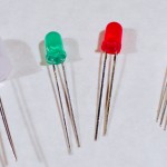
LEDs. Shown here are four LEDs. The one on the right is an RGB LED. You can tell this because it has four legs, while the others have only two legs.
Figure 2. LEDs. Shown here are four LEDs. The one on the right is an RGB LED. You can tell this because it has four legs, while the others have only two legs.
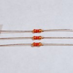
Resistors. Shown here are 220-ohm resistors. You can tell this because they have two red and one brown band, followed by a gold band.
Figure 3. Resistors. Shown here are 220-ohm resistors. You can tell this because they have two red and one brown band, followed by a gold band.
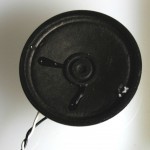
An 8 ohm speaker with 2 wires solder to the speakers leads
Figure 4. An 8 ohm speaker (optional).This is a good alternate to the LED if you prefer audible output.

Prepare the breadboard

Connect power and ground on the breadboard to power and ground from the microcontroller. On the Arduino Uno, use the 5V and any of the ground connections. On the Nano, use 3.3V and the ground connections:

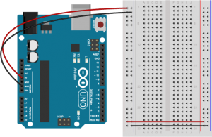
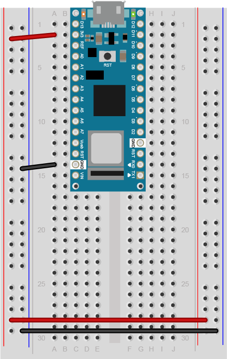
An Arduino Uno on the left connected to a solderless breadboard, right. The Uno's 5V output hole is connected to the red column of holes on the far left side of the breadboard. The Uno's ground hole is connected to the blue column on the left of the board. The red and blue columns on the left of the breadboard are connected to the red and blue columns on the right side of the breadboard with red and black wires, respectively. These columns on the side of a breadboard are commonly called the buses. The red line is the voltage bus, and the black or blue line is the ground bus.
Figure 5. An Arduino Uno on the left connected to a solderless breadboard, right.
Arduino Nano on a breadboard.
Figure 6. Breadboard view of an Arduino Nano mounted on a breadboard.

The +3.3 volts and ground pins of the Arduino Nano are connected by red and black wires(Figure 6), respectively, to the left side rows of the breadboard. +3.3 volts is connected to the left outer side row (the voltage bus) and ground is connected to the left inner side row (the ground bus). The side rows on the left are connected to the side rows on the right using red and black wires, respectively, creating a voltage bus and a ground bus on both sides of the board.Figure 5. Breadboard view of an Arduino Nano connected to a breadboard. The +3.3 volts and ground pins of the Arduino are connected by red and black wires, respectively, to the left side rows of the breadboard. +3.3 volts is connected to the left outer side row (the voltage bus) and ground is connected to the left inner side row (the ground bus). The side rows on the left are connected to the side rows on the right using red and black wires, respectively, creating a voltage bus and a ground bus on both sides of the board.

Made with Fritzing

Add an LED

Connect the LED and resistor to digital I/O pin 11 of the module(Figure 7-8). Alternately, you can replace the 220-ohm LED with a speaker (Figure 9-10). You’ll find code below that uses tones instead of LEDs where appropriate. For more on how to do that, see the Tone Output lab:

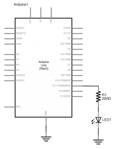
Schematic view of an Arduino connected to an LED. Digital pin 5 is connected to a 22-ohm resistor. The other side of the resistor is connected to the anode (long leg) of an LED. The cathode of the LED is connected to ground.
Figure 7. Schematic view of an Arduino connected to an LED.
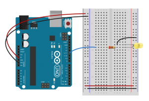
Breadboard view of an Arduino connected to an LED. The +5 volts and ground pins of the Arduino are connected by red and black wires, respectively, to the left side rows of the breadboard. +5 volts is connected to the left outer side row (the voltage bus) and ground is connected to the left inner side row (the ground bus). The side rows on the left are connected to the side rows on the right using red and black wires, respectively, creating a voltage bus and a ground bus on both sides of the board. A blue wire connects Digital to a 22-ohm resistor that straddles the center divide of the breadboard in row 17. The other side of the resistor is connected to the anode (long leg) of an LED. The LED is mounted in rowsd 16 and 17 of the right side of the center section of the board. a black wire connects the cathode's row, row 16, to the ground bus on the right side of the board.
Figure 8. Breadboard view of an Arduino connected to an LED.

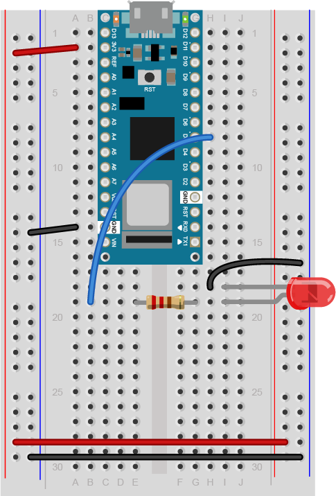
Breadboard view of an LED connected to digital pin 5 of an Arduino Nano.
Figure 9. Breadboard view of an LED connected to digital pin 5 of an Arduino Nano.

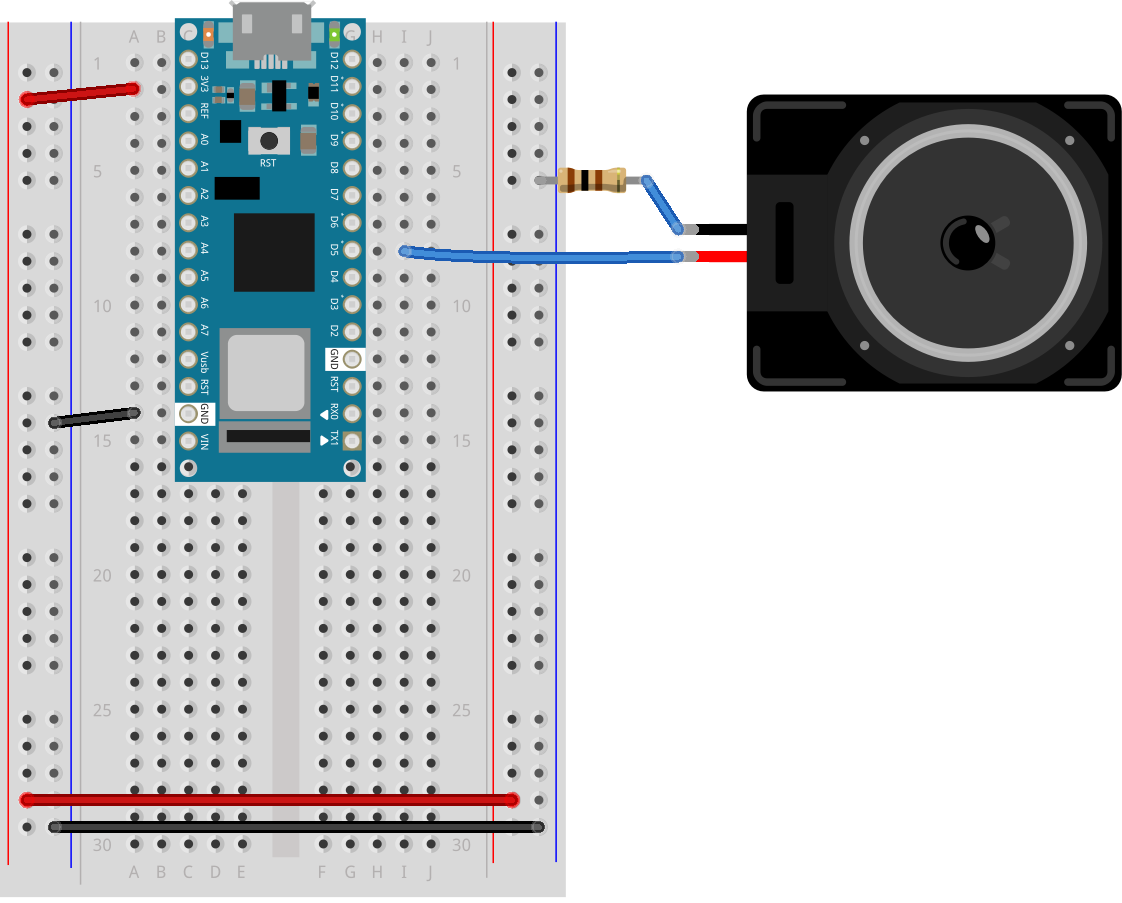
Figure 9 shows a breadboard view of an LED connected to digital pin 5 of an Arduino Nano. The Nano straddles the center of the breadboard in the first fifteen rows. The Nano’s voltage pin (physical pin 2) connects to the board’s voltage bus, and the Nano’s ground pin (physical pin 14) connects to the board’s ground bus. The LED is in the right center of the board, with its anode in one row and the cathode in the next. A 220-ohm resistor connects the LED’s anode to a wire connecting to digital pin 5. The LED’s cathode is connected to the ground bus.

Breadboard view of an Arduino Nano connected to two force sensing resistors (FSRs) and a speaker. The Nano’s 3.3 Volts (physical pin 2) and ground (physical pin 14) are connected to the voltage and ground buses of the breadboard as usual. The red positive wire of the speaker is connected to digital pin 5 of the Arduino. The black ground wire of the speaker is connected to one leg of a 100 ohm resistor. The other leg of the resistor connects to ground.
Figure 10. Breadboard view of an Arduino Nano connected to a speaker to digital pin 5.

Figure 10 shows a breadboard view of an Arduino Nano connected to a speaker. The Nano’s ground (physical pin 14) is connected to the ground bus of the breadboard as usual. The red positive wire of the speaker is connected to digital pin 5 of the Arduino. The black ground wire of the speaker is connected to one leg of a 100 ohm resistor. The other leg of the resistor connects to ground.

Program the Microcontroller

Program your Arduino to read the analog input as follows:

void setup() {
  Serial.begin(9600);     // initialize serial communications
  pinMode(5, OUTPUT);
}

void loop() {
  if (Serial.available() > 0) { // if there's serial data available
    int inByte = Serial.read();   // read it
    Serial.write(inByte);         // send it back out as raw binary data
    analogWrite(5, inByte);       // use it to set the LED brightness
    // if you're using a speaker instead of an LED, uncomment line below  and comment out the previous line:
    //  tone(5, inByte*10);     // play tone on pin 5
  }
}

Only one port at a time can access a serial port.

As you work on this any microcontroller-to-computer application, you will be switching back and forth between the app that programs the microcontroller (in this case, the Arduino IDE) and the app that the microcontroller is communicating with (in this case, p5.js in the browser). You have to keep in mind that only one of these at a time can access a serial port.

That means that when you want to reprogram your Arduino from the Arduino IDE, you should to stop your sketch in the browser window to do so. Then, restart the browser sketch when you’re done reprogramming the Arduino. You don’t need to quit the Arduino IDE each time, because it knows to release the serial port when it’s not programming. However, you do need to close the Serial Monitor in the Arduino IDE when you are using WebSerial in the browser.

The P5.js WebSerial Library

To communicate with your microcontroller serially, you’re going to use the P5.js WebSerial library. If you’re using the p5.js web editor, make a new sketch. Click the Sketch Files tab, and then choose the index.html file. In the head of the document, look for this line:

<script src="https://cdnjs.cloudflare.com/ajax/libs/p5.js/1.4.0/p5.js"></script>

Right after that line, add this line:

<script src="https://unpkg.com/p5-webserial@0.1.1/build/p5.webserial.js"></script>

The P5.js Sketch

The sketch you’re going to write will control the microcontroller’s LED from P5.js. Dragging the mouse up and down the canvas will dim or brighten the LED, and typing 0 through 9 will set the LED’s brightness in increments from off (0) through almost full brightness (9). There’s an alternate sketch that will make changing tones if you prefer that instead of a changing LED. The sketch will also receive serial input from the microcontroller just as in the WebSerial Input to P5.js lab, so that you can see that the microcontroller is getting the same values you’re sending.

The setup of your sketch will initialize the P5.webserial library and define your callback functions for serial events. Program the global variables and setup() function as follows:

// variable to hold an instance of the p5.webserial library:
const serial = new p5.WebSerial();

// HTML button object:
let portButton;
let inData;                            // for incoming serial data
let outByte = 0;                       // for outgoing data

function setup() {
  createCanvas(400, 300);          // make the canvas
  // check to see if serial is available:
  if (!navigator.serial) {
    alert("WebSerial is not supported in this browser. Try Chrome or MS Edge.");
  }
  // if serial is available, add connect/disconnect listeners:
  navigator.serial.addEventListener("connect", portConnect);
  navigator.serial.addEventListener("disconnect", portDisconnect);
  // check for any ports that are available:
  serial.getPorts();
  // if there's no port chosen, choose one:
  serial.on("noport", makePortButton);
  // open whatever port is available:
  serial.on("portavailable", openPort);
  // handle serial errors:
  serial.on("requesterror", portError);
  // handle any incoming serial data:
  serial.on("data", serialEvent);
  serial.on("close", makePortButton);
}

function draw() {

}

For now you’re leaving the draw() function empty. You’ll fill it in later. You’ll be adding some functions to read mouse dragging and key pressing as well.

Program the handler functions similarly to those in the WebSerial Input to P5.js lab:

// if there's no port selected, 
// make a port select button appear:
function makePortButton() {
  // create and position a port chooser button:
  portButton = createButton("choose port");
  portButton.position(10, 10);
  // give the port button a mousepressed handler:
  portButton.mousePressed(choosePort);
}

// make the port selector window appear:
function choosePort() {
  serial.requestPort();
}

// open the selected port, and make the port 
// button invisible:
function openPort() {
  // wait for the serial.open promise to return,
  // then call the initiateSerial function
  serial.open().then(initiateSerial);

  // once the port opens, let the user know:
  function initiateSerial() {
    console.log("port open");
  }
  // hide the port button once a port is chosen:
  if (portButton) portButton.hide();
}

// read any incoming data as a byte:
function serialEvent() {
  // read a byte from the serial port:
  var inByte = serial.read();
  // store it in a global variable:
  inData = inByte;
}

// pop up an alert if there's a port error:
function portError(err) {
  alert("Serial port error: " + err);
}

// try to connect if a new serial port 
// gets added (i.e. plugged in via USB):
function portConnect() {
  console.log("port connected");
  serial.getPorts();
}

// if a port is disconnected:
function portDisconnect() {
  serial.close();
  console.log("port disconnected");
}

function closePort() {
  serial.close();
}

Program the  draw() function to display the value of any incoming serial bytes. Here it is:

function draw() {
  // black background, white text:
  background(0);
  fill(255);
  // display the incoming serial data as a string:
  text("incoming value: " + inData, 30, 30);
}

To read the mouse and keyboard, you’ll need to write functions to respond to the ‘mouseDragged’ and ‘keyPressed’ events. ‘MouseDragged’ will happen whenever you click and drag the mouse on the canvas. When that happens, read the mouseY, and map its position on the canvas to a value from 0 to 255. Convert the result to a number using the int() function. Then send it out the serial port using the serial.write() function:

function mouseDragged() {
  // map the mouseY to a range from 0 to 255:
  outByte = byte(map(mouseY, 0, height, 0, 255));
  // send it out the serial port:
  serial.write(outByte);
}

The serial.write() function is versatile. If you give it a variable or literal that’s a numeric data type, it will send it as its raw binary value. In the code above, note how you’re converting the output of the map() function to a number using the int() function.  If you give it a string, however, it will send out that ASCII string. So be aware of the difference, and make sure you know whether your serial receiving device wants raw binary or ASCII-encoded data.

Program the keyPressed() function similarly to the mouseDragged() function. You want it to read the key strokes, convert them to raw bytes, and send them out the serial port. But you only want to send them if they key hit was 0 through 9. The P5.js variable key returns a numeric value, so you can do math on it and convert it like so:

function keyPressed() {
  if (key >= 0 && key <= 9) { // if the user presses 0 through 9
    outByte = (key * 25); // map the key to a range from 0 to 225
    serial.write(outByte); // send it out the serial port
  }
}

That’s all you want your sketch to do, so try running it now. You should see that the initial incoming serial value is undefined, but when you drag the mouse up and down, or type 0 through 9, it will update when the Arduino program returns what it received. The LED will also change with these actions.

You can see this sketch running on gitHub at this link. You can get the full text of it at this link.

Sending ASCII-Encoded Serial Data

When you send data from p5.js using p5.webserial, the serial.write() function works like it does in Arduino: it sends numbers as binary data. In the programs above, you’re sending binary data from p5.js and reading it as binary in Arduino.

If you want to send ASCII-encoded serial data from P5.js instead, all you have to do is to serial.print() or serial.println() your string. On the Arduino side, you can read single characters one byte at a time simply as well. However, if you want to convert multi-byte number strings to numeric values, you’ll need a new function to read ASCII encoded numeric strings called parseInt().

Program the  Microcontroller Again

To start off with, load a sketch from the Arduino examples called PhysicalPixel. You can find it in the File Menu -> Examples -> Communication -> PhysicalPixel. Here’s what it looks like. Change the LED pin number to pin 5 as follows:

const int ledPin = 5; // the pin that the LED is attached to
int incomingByte;     // a variable to read incoming serial data into

void setup() {
  Serial.begin(9600);             // initialize serial communication
  pinMode(ledPin, OUTPUT);        // initialize the LED pin as an output
}

void loop() {
  if (Serial.available() > 0) { // see if there's incoming serial data
    incomingByte = Serial.read(); // read it
    if (incomingByte == 'H') {    // if it's a capital H (ASCII 72),
      digitalWrite(ledPin, HIGH); // turn on the LED
      // if you're using a speaker instead of an LED, uncomment line below  and comment out the previous line:
      //  tone(5, 440);           // play middle A on pin 5
    }
    if (incomingByte == 'L') {    // if it's an L (ASCII 76)
      digitalWrite(ledPin, LOW);  // turn off the LED
      // if you're using a speaker instead of an LED, uncomment line below  and comment out the previous line:
      // noTone(5);
    }
  }
}

When you run this, open the serial monitor and type H or L, and the LED will go on or off.  Try typing h or l instead. The LED won’t change, because H and h have different ASCII values, as do L and l. But you can see from this that you don’t need to memorize the ASCII chart to check for character values in your code. Put the character you want to read in single quotes, and the Arduino compiler will automatically convert the character to its ASCII value for you. It only works for single characters, though.

Program P5.js To Control the LED

To get P5.js to control this Arduino program serially, you only need to add to the keyPressed() function to read H or L in addition to 0 through 9. Here’s your new mousePressed() function:

function keyPressed() {
  if (key >= 0 && key <= 9) {
    // if the user presses 0 through 9
    outByte = byte(key * 25); // map the key to a range from 0 to 225
    serial.write(outByte); // send it out the serial port
  }
  if (key === "H" || key === "L") {
    // if the user presses H or L
    serial.write(key); // send it out the serial port
  }
}

Because the key is already a single character, P5.js sends it out as is, and Arduino reads it as a single byte, looking for the ASCII value of H or L. Notice how the values returned to P5.js are 72 and 76, the ASCII values for H and L. For single characters like this, exchanging data is simple.

If you tried to change the LED with the mouse, you didn’t see anything happen unless your output value was 72 or 76. Why is that?

To see the sketch running on GitHub at this link. You can see the source files for copying into the p5.js editor at this link.

Processing ASCII-Encoded Strings With Arduino

It is also possible to read and interpret ASCII-encoded strings in Arduino. The String.parseInt() function reads an incoming string until it finds a non-numeric character, then converts the numeric string that it read into a long integer. This is a blocking function, meaning that String.parseInt() stops the program and does nothing until it sees a non-numeric character, or until a timeout passes. The timeout is normally one second (or 1000 milliseconds), but you can set it to a lower number of milliseconds using Serial.setTimeout(). Here’s a variation on the original Arduino sketch from above, using Serial.parseInt() this time:

void setup() {
  Serial.begin(9600);    // initialize serial communications
  Serial.setTimeout(10); // set the timeout for parseInt
  pinMode(5, OUTPUT);
}

void loop() {
  if (Serial.available() > 0) { // if there's serial data available
    int inByte = Serial.parseInt(); // read it
    if (inByte > 0) {
      Serial.write(inByte);      // send it back out as raw binary data
      analogWrite(5, inByte);    // use it to set the LED brightness
      // if you're using a speaker instead of an LED, uncomment line below  and comment out the previous line:
      //  tone(5, inByte*10);     // play tone on pin 5
    }
  }
}

Upload this to your microcontroller, then open the Serial Monitor and send in some ASCII numeric strings. You’ll see the character that’s represented by the string’s value. For example, 65 will return A, 34 will return “, and so forth.Notice that this version of the sketch has a conditional statement to check if the incoming byte is 0. This is because of a quirk of the parseInt() function. It returns 0 if the timeout is hit, or if the string is legitimately 0. This means you can’t really parse for a string like this: "0\n".

Program p5.js To Send a String

Now that your microcontroller is expecting a string, program P5.js to send one. This means changing the mouseDragged() function. Program it to print a string with a newline at the end using the serial.println() command like so:

serial.println(outByte);

Since the newline added at the end by serial.println() is a non-numeric character, the Serial.parseInt() function will see it and parse the string, not waiting for the timeout.

To see the sketch running on GitHub at this link. You can see the source files for copying into the p5.js editor at this link.

Conclusion

When you’re sending data between two computers using asynchronous serial communication, you have to make sure that what the sender is sending is formatted the same as what the receiver is listening for. See Table 1 to review what are suitable data formats for different types/sizes of data and which functions to use on p5.js and Arduino for serial communication.

Number of Bytes
1 Byte
Multi Bytes
Data to Send
A single number < 255
A single character
A single number > 255, multiple values
Send as:
Binary
Ascii
Ascii
p5.js ->
serial.write(integer)
serial.write(string)
serial.write
(valueToSend + ",")
-> Arduino
Serial.read()
Serial.parseInt()

Table 1. Serial Communication: p5.js to Arduino

Think this out in advance before you code, then consider what functions you’ve got on both computers to convert data from strings to raw binary numbers and back. Test with fixed values at first, so you know you’re getting what you think you should. For example, sending an ASCII-encoded numeric string like this:

1023\n

Will always result in these six bytes:

49 48 50 51 10

Likewise, this text string:

Hello\n

will always be:

72 101 108 108 111 10

By sending a string you know both the ASCII and raw binary representations of, you can test your code easier, because what you’re sending won’t change. Once you know the sending and receiving works, then you can send variable strings.

The more you work with serial data, the more you’ll become familiar with the methods for handling it.

For more on serial flow control in P5.js, see the Two-Way Duplex Serial Communication Using p5.WebSerial Lab.

Lab: Serial Input to p5.js Using the p5.webserial Library

This lab uses a p5.js library called p5.WebSerial to make it easy in p5.js. In this lab, you’ll generate an analog output value from a potentiometer, then send that value via asynchronous serial communication to P5.js. You’ll use that value in P5.js to draw a graph.

Web browsers have traditionally been designed to be separate from the rest of a computer’s operating system, not able to connect to the computer’s hardware ports for security reasons. Recently, however, the W3C developed the WebSerial API in JavaScript, which allows browsers to communicate with a computer’s serial ports. WebSerial is currently only available in the Chrome and Chromium browsers and the Microsoft Edge browser, so make sure you’re using one of those to do this lab.

To get the most out of this tutorial, you should know what a microcontroller is and how to program them. You should also understand asynchronous serial communication between microcontrollers and personal computers. You should also understand the basics of P5.js.

Once you gain an understanding of serial communication, you can use any program that can connect with your computer’s serial ports to communicate with a microcontroller. In addition to the WebSerial API you’ll see here, you can use other programming environments to communicate serially. Processing, Max/MSP, and OpenFrameworks are three other popular multimedia programming environments that can communicate via the serial ports. You can also do this with Unity, Unreal, or any other programming environment that can access the serial ports.

Things You’ll Need

For this lab, you’ll need the hardware below, and you’ll need to create a p5.js sketch. You’ll also use the p5.WebSerial library. You can use the p5.js web editor or your favorite text editor for this (the Visual Studio Code editor works well).

Figures 1-4 below show the parts you’ll need for this exercise. Click on any image for a larger view.

Photo of an Arduino Nano 33 IoT module. The USB connector is at the top of the image, and the physical pins are numbered in a U-shape from top left to bottom left, then from bottom right to top right.
Figure 1. Microcontroller. Shown here is an Arduino Nano 33 IoT
Photo of flexible jumper wires
Figure 2. Jumper wires.  You can also use pre-cut solid-core jumper wires.
Photo of a solderless breadboard
Figure 3. A solderless breadboard
Photo of two potentiometers
Figure 4. Potentiometer

Prepare the Breadboard

For this exercise you’re going to attach a potentiometer as an analog input to your microcontroller, and send the sensor’s reading serially to p5.js via the p5.serialcontrol app.

Connect power and ground on the breadboard to the microcontroller. On the Arduino module, use the 5V or 3.3V (depending on your model) and any of the ground connections. Figures 5 and 6 show connections for an Arduino Uno and a Nano, respectively.

An Arduino Uno on the left connected to a solderless breadboard, right. The Uno's 5V output hole is connected to the red column of holes on the far left side of the breadboard. The Uno's ground hole is connected to the blue column on the left of the board. The red and blue columns on the left of the breadboard are connected to the red and blue columns on the right side of the breadboard with red and black wires, respectively. These columns on the side of a breadboard are commonly called the buses. The red line is the voltage bus, and the black or blue line is the ground bus.
Figure 5. An Arduino Uno on the left connected to a solderless breadboard, right.

The Uno’s 5V output hole is connected to the red column of holes on the far left side of the breadboard (Figure 5). The Uno’s ground hole is connected to the blue column on the left of the board. The red and blue columns on the left of the breadboard are connected to the red and blue columns on the right side of the breadboard with red and black wires, respectively. These columns on the side of a breadboard are commonly called the buses. The red line is the voltage bus, and the black or blue line is the ground bus.


Arduino Nano on a breadboard.
Figure 6. Breadboard view of an Arduino Nano mounted on a breadboard.

Images made with Fritzing, a circuit drawing application

The Nano is mounted at the top of the breadboard (Figure 6), straddling the center divide, with its USB connector facing up. The top pins of the Nano are in row 1 of the breadboard.

The Nano, like all Dual-Inline Package (DIP) modules, has its physical pins numbered in a U shape, from top left to bottom left, to bottom right to top right. The Nano’s 3.3V pin (physical pin 2) is connected to the left side red column of the breadboard. The Nano’s GND pin (physical pin 14) is connected to the left side black column. These columns on the side of a breadboard are commonly called the buses. The red line is the voltage bus, and the black or blue line is the ground bus. The blue columns (ground buses) are connected together at the bottom of the breadboard with a black wire. The red columns (voltage buses) are connected together at the bottom of the breadboard with a red wire.


Add a Potentiometer

Connect a potentiometer to analog in pin 0 of the module. Figure 7 shows the schematic and figures 8 and 9 show the potentiometer connected to an Arduino and Nano, respectively.

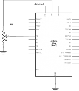
Schematic view of a potentiometer. First leg of the potentiometer is connected to +5 volts. The second leg connected to analog in 0 of the Arduino. The third leg is connected to ground.
Figure 7. Schematic view of a potentiometer connected to analog in 0 of the Arduino
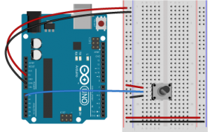
Breadboard view of a potentiometer. First leg of the potentiometer is connected to +5 volts. The second leg connected to analog in 0 of the Arduino. The third leg is connected to ground.
Figure 8. Breadboard view of a potentiometer connected to analog in 0 of an Arduino. The potentiometer is connected to three rows in the left center section of the breadboard. The two outside pins are connected to voltage and ground. The center pin is connected to the Arduino’s analog in 0.

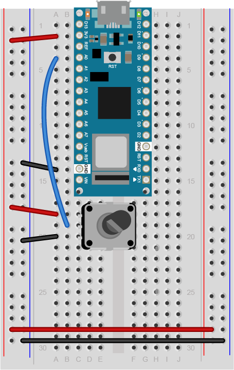
Breadboard view of Arduino Nano with an potentiometer input.
Figure 9. Breadboard view of a potentiometer connected to analog in 0 of an Arduino Nano. The Nano is connected as usual, straddling the first fifteen rows of the breadboard with the USB connector facing up. Voltage (physical pin 2) is connected to the breadboard’s voltage bus, and ground (physical pin 14) is connected to the breadboard’s ground bus. The potentiometer is connected to three rows in the left center section of the breadboard. The two outside pins are connected to voltage and ground. The center pin is connected to the Nano’s analog in 0.

Program the Microcontroller

Program your Arduino to read the analog input as follows:

void setup() {
  Serial.begin(9600); // initialize serial communications
}

void loop() {
  // read the input pin:
  int potentiometer = analogRead(A0);                  
  // remap the pot value to fit in 1 byte:
  int mappedPot = map(potentiometer, 0, 1023, 0, 255); 
  // print it out the serial port:
  Serial.write(mappedPot);                             
  // slight delay to stabilize the ADC:
  delay(1);                                            
}

Only one port at a time can access a serial port.

As you work on this any microcontroller-to-computer application, you will be switching back and forth between the app that programs the microcontroller (in this case, the Arduino IDE) and the app that the microcontroller is communicating with (in this case, p5.js in the browser). You have to keep in mind that only one of these at a time can access a serial port.

That means that when you want to reprogram your Arduino from the Arduino IDE, you should to stop your sketch in the browser window to do so. Then, restart the browser sketch when you’re done reprogramming the Arduino. You don’t need to quit the Arduino IDE each time, because it knows to release the serial port when it’s not programming. However, you do need to close the Serial Monitor in the Arduino IDE when you are using WebSerial in the browser.

The P5.js WebSerial Library

To communicate with your microcontroller serially, you’re going to use the P5.js WebSerial library. If you’re using the p5.js web editor, make a new sketch. Click the Sketch Files tab, and then choose the index.html file. In the head of the document, look for this line:

<script src="https://cdnjs.cloudflare.com/ajax/libs/p5.js/1.4.0/p5.js"></script>

Right after that line, add this line:

 <script src="https://unpkg.com/p5-webserial@0.1.1/build/p5.webserial.js"></script>

The p5.js Sketch

To start off, you need to know if WebSerial is supported in the browser you’re using. Open the sketch.js file and change it to the following:

// variable to hold an instance of the p5.webserial library:
const serial = new p5.WebSerial();

function setup() {
   // check to see if serial is available:
   if (!navigator.serial) {
    alert("WebSerial is not supported in this browser. Try Chrome or MS Edge.");
  } 
}

When you run this p5.js sketch in a browser, you’ll get a message letting you know whether or not this browser supports WebSerial. In a browser that supports WebSerial, you may want to delete the else clause.

 Serial Events

JavaScript, the language on which p5.js is based, relies heavily on events and callback functions. An event is generated by the operating system when something significant happens, like a serial port opening, or new data arriving in the port. In your sketch, you write a callback function to respond to that event. The p5.webserial library uses events and callback functions as well. It can listen for the following serialport events:

  • noport – when there is no selected serial port
  • portavailable – when a serial port becomes available
  • data – new data arrives in a serial port
  • close – the serial port is closed
  • requesterror – something goes wrong when you request a serial port.

The WebSerial API on which the p5.webserial library is based also has connect and disconnect events for when a serial port is physically disconnected (or in the case of a USB-native device like the Nano 33 IoT, when it is reset). You’ll see those below as well, and you’ll see them run whenever the serial connection to the Arduino is reset.

To use the the webserial library’s events, you need to set callback functions for them. Change your sketch to include a port chooser button and a variable for incoming data, then in the setup() function, add callbacks for open, close, and data, and error like so:

// variable to hold an instance of the p5.webserial library:
const serial = new p5.WebSerial();

// HTML button object:
let portButton;
let inData;                   // for incoming serial data
let outByte = 0;              // for outgoing data

function setup() {
  createCanvas(400, 300);          // make the canvas
  // check to see if serial is available:
  if (!navigator.serial) {
    alert("WebSerial is not supported in this browser. Try Chrome or MS Edge.");
  }
  // if serial is available, add connect/disconnect listeners:
  navigator.serial.addEventListener("connect", portConnect);
  navigator.serial.addEventListener("disconnect", portDisconnect);
  // check for any ports that are available:
  serial.getPorts();
  // if there's no port chosen, choose one:
  serial.on("noport", makePortButton);
  // open whatever port is available:
  serial.on("portavailable", openPort);
  // handle serial errors:
  serial.on("requesterror", portError);
  // handle any incoming serial data:
  serial.on("data", serialEvent);
  serial.on("close", makePortButton);
}

function draw() {


}

The draw() function is empty for the moment. You’ll come back and fill that in later.

Now that you’ve set listeners for the events, you need to add the callback functions. Here they are. Add these after the draw() function:

// if there's no port selected, 
// make a port select button appear:
function makePortButton() {
  // create and position a port chooser button:
  portButton = createButton("choose port");
  portButton.position(10, 10);
  // give the port button a mousepressed handler:
  portButton.mousePressed(choosePort);
}

// make the port selector window appear:
function choosePort() {
  if (portButton) portButton.show();
  serial.requestPort();
}

// open the selected port, and make the port 
// button invisible:
function openPort() {
  // wait for the serial.open promise to return,
  // then call the initiateSerial function
  serial.open().then(initiateSerial);

  // once the port opens, let the user know:
  function initiateSerial() {
    console.log("port open");
  }
  // hide the port button once a port is chosen:
  if (portButton) portButton.hide();
}

// pop up an alert if there's a port error:
function portError(err) {
  alert("Serial port error: " + err);
}
// read any incoming data as a string
// (assumes a newline at the end of it):
function serialEvent() {
  inData = Number(serial.read());
  console.log(inData);
}

// try to connect if a new serial port 
// gets added (i.e. plugged in via USB):
function portConnect() {
  console.log("port connected");
  serial.getPorts();
}

// if a port is disconnected:
function portDisconnect() {
  serial.close();
  console.log("port disconnected");
}

function closePort() {
  serial.close();
}

Wait a Minute! Don’t I have to Set the Data Rate When I Open the Port?

In asynchronous serial communications, both computers have to set the same data rate in order to communicate. In Arduino, you set the data rate with Serial.begin(9600); In p5.webserial, 9600 bits per second is the default, so you don’t have to set the rate if you want 9600bps. But if you want to set the rate to another value, change your serial.open() call in the openPort() function as follows:

let options = { baudrate: 9600}; // change the data rate to whatever you wish
serial.open(portName, options);

There are other port options you can set using p5.webserial, including baudRate, bufferSize,  dataBits,  flowControl,  parity and  stopBits. These are all standard serialport options, and most programming environments which support serial communication will have them. You can get details of these in the p5.webserial documentation.

p5.WebSerial Sketch Checklist

Most p5.WebSerial sketches that you write will have a similar structure to this one. The main difference between them all will be how you read and interpret incoming serial data, and how and when you send and format outgoing serial data. Here’s a checklist of the pieces you’re likely to see in every sketch:

  • In the HTML file, include the p5.webserial library
  • In the global variables of the sketch,
    • make a new instance of the library
    • include a port selector button or some way to invoke the serial port chooser dialogue box
  • In the setup:
    • Make sure WebSerial is supported in this browser
    • Include a call to serial.getPorts() to check for available ports.
    • include serial.on() listeners for these events:
      • noport
      • portavailable
      • data
      • close
      • requesterror
    • include navigator listeners for connect and disconnect
  • Define handler functions for all of the events above. Most of these can be simple alerts or console.log messages
  • Customize the function that responds to the data listener (usually called serialEvent() in these examples), as you’ll see below.
  • Decide when and how you’ll send serial data out, as you’ll see in the other p5.webserial labs.

The last two items of this list are the ones on which you’ll spend most of your time. The rest of the items are things you’re likely to copy from one sketch to another.

Reading Incoming Serial Data

The event that that you’ll use the most is the data event, which calls the serialEvent() function. Each time a new byte arrives in the serial port, this function is called. Now it’s time to make serialEvent() do some work. Add a new global variable at the top of your sketch called inData like so:

The serialEvent() function you added above looks like this:

function serialEvent() {
  inData = Number(serial.read());
  console.log(inData);
}

It’s reading the incoming data byte by byte, and interpreting each byte as a number. That’s why the Number() function surrounds the read() function. Since you’re sending the data from the Arduino as a binary value (using the Serial.write() function), you have to interpret it in p5.js as a binary value as well.

Next, make the draw() function to print the sensor value to the screen like so:

function draw() {
   background(0);
   fill(255);
   text("sensor value: " + inData, 30, 50);
}
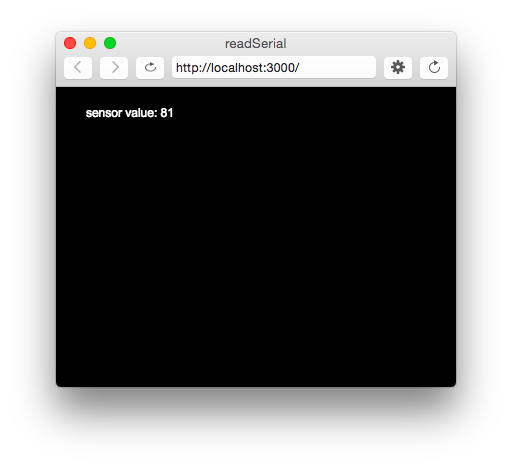
A screenshot of the sketch running in a browser.
Figure 10. A screenshot of the sketch running in a browser. The sketch prints the sensor value in text on the screen.

When you run your sketch now, you should get something like the sketch shown in Figure 10.

To see the sketch running on GitHub at this link. You can see the source files for copying into the p5.js editor at this link.

The sensor value onscreen should change as you turn your potentiometer. Congratulations! You’ve got P5.js talking to your microcontroller.

What’s Happening Here

Every time your microcontroller sends a byte serially using Serial.write(), the computer receives it and generates a ‘data’ event. Then your serialEvent() function is called. It reads the byte as a number, and stores it in the global variable inData. The draw() method just uses the latest value of inData in the text string it displays on the screen.

You may be wondering why you’re mapping the sensor value or dividing it by 4 in the Arduino sketch above. That’s because in order to send the sensor value as a single byte, it must be between 0 and 255, or no more than 28 bits.

P5.js Console.log() and Arduino delay(): a Tricky Combination

In testing this, you may have put a console.log() statement in the serialEvent() function in your P5.js sketch. When you did, you would have noticed that it causes a lag in the sketch, and the console.log() statements continue even after you stop the sketch. This is because the operating system keeps the incoming serial data in a buffer, and P5.js isn’t reading and printing it as fast as Arduino is sending it.

You might think, “Okay, then I’ll just put a delay() in my Arduino sketch to slow it down.” That’s a bad idea. When you put in a delay, it means you’re only reading your sensor when that delay is not running.  You can miss critical sensor events while that delay is in progress. Even a relatively small delay, for example 30ms, can make it difficult to reliably read state changes in a switch or peaks in an analog sensor. Don’t use delays if you can avoid it. For more on how to handle the flow of serial data from Arduino to P5.js and back, see the Duplex Serial Flow using WebSerial in P5.js lab.

Draw a Graph With the Sensor Values

It would be useful to see a graph of the sensor values over time. You can do that by modifying the draw() method to draw the graph. To do this, add a new global variable at the top of your sketch called xPos. You’ll use this to keep track of the x position of the latest graph line:

let xPos = 0;                     // x position of the graph

Because of the way the graphing function below works, you can’t reset the background every time through the draw() loop. So take the background() command and put it in the setup() function instead of the draw(), as shown below. That way it runs once, then not again. As long as you’re at it, switch from black & white to a nice blue color:

function setup() {
  createCanvas(400, 300);
  background(0x08, 0x16, 0x40);

Now make a new function called graphData(). It’ll take a number value as a parameter, and it will draw a line on the screen that’s mapped to the number value. Then it will increment xPos so that the next line is drawn further along. It will also check if the xPos is at the right edge of the screen, and reset the screen by calling background() again if it is:

function graphData(newData) {
  // map the range of the input to the window height:
  var yPos = map(newData, 0, 255, 0, height);
  // draw the line in a pretty color:
  stroke(0xA8, 0xD9, 0xA7);
  line(xPos, height, xPos, height - yPos);
  // at the edge of the screen, go back to the beginning:
  if (xPos >= width) {
    xPos = 0;
    // clear the screen by resetting the background:
    background(0x08, 0x16, 0x40);
  } else {
    // increment the horizontal position for the next reading:
    xPos++;
  }
}

Finally, take everything out of the draw() function and just call graphData() from there:

function draw() {
  graphData(inData);
}

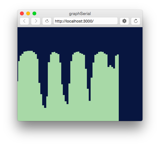
When you run the sketch now, you should get a graph, as shown in Figure 11.

Screenshot of the serial graph p5.js sketch.
Figure 11. Screenshot of the serial graph p5.js sketch. The sensor’s values are graphed on the screen

To see the sketch running on GitHub at this link. You can see the source files for copying into the p5.js editor at this link.

Reading Serial Data as a String

This works well if you want to read your sensor values as a single byte, but what if you want a larger range of numbers?  What if you want the full 0 to 1023 that analogRead() can output instead of just 0 to 255?  To do this, you need to send the data as an ASCII-encoded numeric string from the microcontroller, and you need to read and interpret the incoming data in P5 as an ASCII-encoded numeric string as well.

Change your Arduino program to the following:

void setup() {
 Serial.begin(9600); // initialize serial communications
}

void loop() {
 int potentiometer = analogRead(A0);                  // read the input pin
 int mappedPot = map(potentiometer, 0, 1023, 0, 255); // remap the pot value to fit in 1 byte
 Serial.println(mappedPot);                           // print it out the serial port
 delay(1);                                            // slight delay to stabilize the ADC
}

Now it will print the potentiometer’s value as an ASCII-encoded numeric string, and it will add a carriage return byte and a newline byte at the end, because that’s what println() does.

Once you’ve uploaded this to your Arduino, run your P5 sketch again. Try adding println(inData); at the end of your serialEvent() function. When your P5 sketch reads the data from this Arduino program, you get very low values, and every so often you see the value 10 followed by the value 13. What’s going on?

When a computer ASCII-encodes a number, it converts that number to a string of bytes, each of which is the ASCII value for a numeral in the number. For example, the number 865 gets converted to three bytes, as shown in Figure 12.

ASCII representation of a three-digit number.
Figure 12. The decimal number 865 when sent serially as ASCII is three bytes long. The first byte representing digit, 8, has the ASCII value 58. The second byte representing the digit 6 has the ASCII value 54. The third byte representing the digit 5 has the ASCII value 53.

If there’s a carriage return byte and a newline byte after this, the string is five bytes, and the last two bytes’ values are 13 (carriage return, or \r in most programming languages) and 10 (newline or \n in most programming languages), respectively.

Your P5.js sketch is reading every byte’s value and graphing it. That’s why you get a graph of very low values, with a bunch of them being 13 and 10. The Arduino is ASCII-encoding the potentiometer values, but the P5 sketch is interpreting the bytes as if they’re not encoded that way.

Now change the serialEvent() function like so:

function serialEvent() {
  // read a byte from the serial port, convert it to a number:
  inData = serial.readLine();
}

Run it again. What’s changed? Now you’re getting a graph kind of like you were before. The serial.readLine(); command reads the incoming serial data as a string, and when that string happens to be all-numeric, it converts it to a number. So you’re getting the ASCII-encoded string as a number again. But sometimes there are gaps. Why?

Remember, the ‘data’ event occurs every time a new byte comes in the serial port. Now that you’re sending an ASCII-encoded string, every potentiometer reading is several bytes long. So you only get a complete string every three to six bytes (three for “0\r\n” and six for “1023\r\n”). Sometimes, when the serialEvent() function calls serial.readLine(); it gets nothing. That’s when draw() draws the gaps. You need to change your function to check that the resulting string is actually a valid number before you put the string into inData. First, create a local variable to get the string, then check to see if the string’s length is greater than zero. If it is, then put it into inData so that the other functions in the sketch can use the new data. Here’s how you do that:

function serialEvent() {
  // read a string from the serial port:
  var inString = serial.readLine();
  // check to see that there's actually a string there:
  if (inString) {
  // convert it to a number:
  inData = Number(inString);
  }
}

Now you’re able to send in a number of any value to P5.js. You don’t have to limit your input to a 0-255 value range. See if you can modify the Arduino sketch and the P5.js sketch to exchange a potentiometer value that spans the whole range from 0 to 1023.

note: readLine() is the same as readStringUntil(‘\r\n’);

You can see the sketch running on GitHub at this link. You can see the source files for copying into the p5.js editor at this link.

Conclusion

In this lab, you saw how to connect an Arduino microcontroller to a P5.js sketch using a webSocket-to-serial server, P5.serialserver, and the P5.serialport library. You sent data from Arduino to the sketch as a raw binary value — that is, a single byte ranging from 0 to 255 — and you sent it as an ASCII-encoded numeric string with a carriage return and newline at the end. See Table 1 below to review what are suitable data formats for different types/sizes of data and which functions to use on p5.js and Arduino for serial communication.

Data to Send
A single value
within 0-255
(< 2^8 = 1 byte)
Larger numbers & characters in Ascii Table,
Multiple values
Send as:
Binary
Ascii
Arduino ->
Serial.write()
Serial.println()
-> p5.js
serial.read()
serial.readLine()
=readStringUntil('\r\n')

Table 1. Serial Communication: Arduino to p5.js

Notes about sending ASCII-encoded data:

  • Using Serial.println() on Arduino and serial.readLine() on p5.js is one of many different ways of sending data from Arduino to p5.js via serial communication.
  • If you want to read an ASCII-encoded numeric string as a number and not a string, convert the value into number by using Number()

Understanding the difference between ASCII-encoded strings and raw binary data is central to all serial communications. For more examples of this in action, see the WebSerial Output from P5.js lab.

p5.serialport and p5.webserial Compared

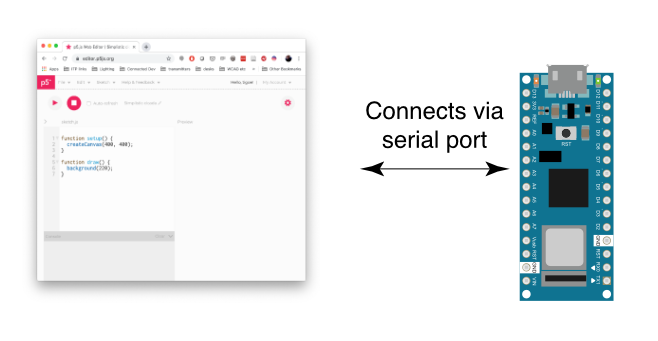
Asynchronous serial communication is not part of the core of p5.js, nor is it part of the core for web browsers. To read serial in a p5.js sketch, or in a web page in general, you need some help. One approach is to open a separate application that connects to the serial port and offers a webSocket connection to the browser. This is the approach that the p5.serialport library and the p5.serialcontrol app take. Another approach is to use the browser API called WebSerial. This is the approach that the p5.webserial library takes.

The difference between them is best illustrated by Figures 1 and 2 below. With p5.seriaport, you must open another application on your computer, p5.serialcontrol, to communicate with the serial port. It is this application that handles serial communication, not the p5.js sketch in the browser. This can be more complicated for beginning users.

Diagram of three rectangles connected by arrows. The rectangle on the right represents your p5.js sketch, running in a browser. Your sketch implements the p5.serialport library. Your sketch connects to p5 serial control, the middle rectangle, via a webSocket. The p5 serial control application runs on your laptop. It connects to a serial port on your computer and listens for webSocket connections from your p5.js sketch. It passes whatever comes in the serial port through to the webSocket and vice versa. The third rectangle is your Arduino, connected to p5 serial control via the serial port.
Figure 1. Diagram of the connection from the serial port to p5.js through p5.serialcontrol
Diagram of two rectangles connected by arrows. The rectangle on the right represents your p5.js sketch, running in a browser. Your sketch implements the p5.webserial library. The browser connects to a serial port on your computer. It passes whatever comes in the serial port through to the webSocket and vice versa. The second rectangle is your Arduino, connected via the serial port.
Figure 2. Diagram of the connection from the serial port to p5.js through p5.webserial
p5.serialport/p5.serialcontrol:p5.webserial:
advantages:
* works in all browsers.
* Allows your browser to connect to the serial port of a remote computer, if that computer is running a web server program.
* Supports opening multiple serial ports at the same time
advantages:
* connection is direct to the browser, making it easier for beginners to learn


disadvantages:
* requires a third application (p5.serialcontrol), making it more difficult for beginners to learn
disadvantages:
* only works in Chrome and Edge browsers
* No connection to remote computers
* Not sure if it supports a second serial port.
Table 1. Comparing p5.seriaport to p5.webserial

The APIs of p5.serialport and p5.webserial are similar, so it’s pretty straightforward to convert between them.

The code below is a typical p5.serialport setup. You make an instance of the p5.serialport library with the port name, then you make callback functions for the primary tasks:

let serial;          // variable to hold an instance of the serialport library
let portName = '/dev/cu.usbmodem1421';  // fill in your serial port name here
 
function setup() {
  serial = new p5.SerialPort();       // make a new instance of the serialport library
  serial.on('list', printList);  // set a callback function for the serialport list event
  serial.on('connected', serverConnected); // callback for connecting to the server
  serial.on('open', portOpen);        // callback for the port opening
  serial.on('data', serialEvent);     // callback for when new data arrives
  serial.on('error', serialError);    // callback for errors
  serial.on('close', portClose);      // callback for the port closing
 
  serial.list();                      // list the serial ports
  serial.open(portName);              // open a serial port
}

The code below is a typical p5.webserial setup. You check t see if WebSerial is available, and then you make an instance of the p5.webserial library, then you look for ports using getPorts():

// variable to hold an instance of the p5.webserial library:
const serial = new p5.WebSerial();
 // port chooser button:
let portButton;
// variable for incoming serial data:
let inData;
 
function setup() {
   // check to see if serial is available:
   if (!navigator.serial) {
    alert("WebSerial is not supported in this browser. Try Chrome or MS Edge.");
  }
  // check for any ports that are available:
  serial.getPorts();
  // setup function continues below:

Unlike with p5.serialport, you don’t pass in the port name. Instead, the user chooses the port with a pop-up menu:

  // if there's no port chosen, choose one:
  serial.on("noport", makePortButton);
  // open whatever port is available:
  serial.on("portavailable", openPort);
  // setup function continues below:

Then you make callback functions for the primary tasks. These are similar to p5.serialport’s callbacks:

   // handle serial errors:
  serial.on("requesterror", portError);
  // handle any incoming serial data:
  serial.on("data", serialEvent);
  serial.on("close", makePortButton)
  // setup function continues below:

You also add listeners for when the USB serial port enumerates or de-enumerates. This way, if you unplug your serial device or reset it, your program automatically reopens it when it’s available:

  
  // add serial connect/disconnect listeners from WebSerial API:
  navigator.serial.addEventListener("connect", portConnect);
  navigator.serial.addEventListener("disconnect", portDisconnect);
} // end of setup function

The functions in each API are similar too:

p5.serialport functions (from the library’s guide)p5.webserial functions (from the library’s guide)
read() returns a single byte of data (first in the buffer)read() — reads a single byte from the queue (returns a number)

readChar() returns a single char, e,g, ‘A’, ‘a’
readChar() — reads a single byte from the queue as a character (returns a string)

readBytes() returns all of the data available as an array of bytes
readBytes() — reads all data currently available in the queue as a Uint8Array.
readBytesUntil(charToFind) returns all of the data available until charToFind is encounteredreadBytesUntil(charToFind) — reads bytes until a character is found (returns a Uint8Array)

readString() returns all of the data available as a string
readStringUntil(charToFind) returns all of the data available as a string until charToFind is encounteredreadStringUntil(stringToFind) — reads out a string until a certain substring is found (returns a string)
last() returns the last byte of data from the buffer

lastChar() returns the last byte of data from the buffer as a char
readLine() — read a string until a line ending is found (returns a string)
write() – sends most any JS data type out the port.write() – sends most any JS data type out the port.
print()– sends string data out the serial port
println() – sends string data out the serial port, along with a newline character.
Table 2. Comparison of p5.serialport and p5.webserial APIs

Both p5.serialport and p5.webserial will do the job of getting bytes from a serial device like an Arduino or other microcontroller to p5.js and vice versa. Which you use depends on what you need. p5.webserial is great if you’re connected directly to the browser’s computer via USB. For most serial applications, this is the way to go. Alternately, p5.serialport offers the advantage that you can run p5.serialcontrol app on your browser’s computer or on another computer on the same network. That way, a browser on your phone or tablet can communicate to the serial device via the computer running p5.serialcontrol.

This site contains lab examples for both p5.serialport and p5.webserial for your convenience.

Lab: Serial IMU Output to p5.js Using p5.webserial

In this exercise you’ll read the built-in Inertial Motion Unit on the Arduino Nano 33 IoT, then feed its output into a Madgwick filter to determine heading, pitch, and roll of the board. Then you’ll send the output of that serially to p5.js and use it to move a virtual version of the Nano onscreen.

Introduction

In this exercise you’ll read the built-in Inertial Motion Unit on the Arduino Nano 33 IoT, then feed its output into a Madgwick filter to determine heading, pitch, and roll of the board. Then you’ll send the output of that serially to p5.js and use it to move a virtual version of the Nano onscreen.

What You’ll Need to Know

To get the most out of this lab, you should be familiar with the following concepts and you should install the Arduino IDE on your computer. You can check how to do so in the links below:

Things You’ll Need

The only part you’ll need for this exercise is an Arduino Nano 33 IoT and its built-in IMU, as shown in Figure 1. You can modify this exercise to work with other IMUs, however. There are details on various IMUs on the accelerometers, gyrometers, and IMUs page.

Photo of an Arduino Nano 33 IoT module. The USB connector is at the top of the image, and the physical pins are numbered in a U-shape from top left to bottom left, then from bottom right to top right.
Figure 1. Microcontroller. Shown here is an Arduino Nano 33 IoT.

Prepare the Breadboard

because the Nano 33 IoT has a built-in IMU, there is no additional circuit needed for this exercise. However, there are two libraries you’ll need to install: the Arduino_LSM6DS3 library, which allows you to read the IMU, and the MadgwickAHRS library, which takes the raw accelerometer and gyrometer inputs and provides heading, pitch, and roll outputs. Both libraries can be found in the Library Manager of the Arduino IDE. Install them before proceeding.

Program the Microcontroller to Read the IMU

The first thing to do in the microcontroller code is to confirm that your accelerometer and gyrometer are working. Start with the code below:

#include "Arduino_LSM6DS3.h"

void setup() {
  Serial.begin(9600);
  // attempt to start the IMU:
  if (!IMU.begin()) {
    Serial.println("Failed to initialize IMU");
    // stop here if you can't access the IMU:
    while (true);
  }
}

void loop() {
  // values for acceleration and rotation:
  float xAcc, yAcc, zAcc;
  float xGyro, yGyro, zGyro;

  // check if the IMU is ready to read:
  if (IMU.accelerationAvailable() && IMU.gyroscopeAvailable()) {
    // read accelerometer and gyrometer:
    IMU.readAcceleration(xAcc, yAcc, zAcc);
    IMU.readGyroscope(xGyro, yGyro, zGyro);

    Serial.print("sensors: ");
    Serial.print(xAcc);
    Serial.print(",");
    Serial.print(yAcc);
    Serial.print(",");
    Serial.print(zAcc);
    Serial.print(",");
    Serial.print(xGyro);
    Serial.print(",");
    Serial.print(yGyro);
    Serial.print(",");
    Serial.println(zGyro);
  }
}

When you run this sketch and open the Serial Monitor, you should see a printout with six values per line. The first three are your accelerometer values, and the next three are your gyrometer values. The following reading is typical:

sensors: 0.04,-0.05,1.02,3.05,-3.72,-1.77

The Nano 33 IoT’s accelerometer’s range is fixed at +/-4G by this library, and its gyrometer’s range is set at +/-2000 degrees per second (dps). The sampling rate for both is set to 104 Hz by the library. Other IMUs may have differing ranges. You need to know at least the sampling rate when you want to use a different IMU with this exercise. If you know that information, though, it’s easy to swap one IMU for another in the Madgwick library.

Add the Madgwick Library to Get Orientation

The MadgwickAHRS library can work with any accelerometer/gyrometer combination. It expects the acceleration in Gs and the rotation in degrees per second as input, and uses the sensors’ sampling rate when you initialize it. Add a few lines to the code before your setup() as follows:

#include "Arduino_LSM6DS3.h"
#include "MadgwickAHRS.h"

// initialize a Madgwick filter:
Madgwick filter;
// sensor's sample rate is fixed at 104 Hz:
const float sensorRate = 104.00;

// values for orientation:
float roll = 0.0;
float pitch = 0.0;
float heading = 0.0;

Next, add the following line at the end of the setup() to initialize the Madgwick filter:

// start the filter to run at the sample rate:
filter.begin(sensorRate);

Now change the main loop so that you’re sending the sensor readings into the Madgwick filter. You’ll do this inside of the if statement that checks if the sensors are ready:

// check if the IMU is ready to read:
if (IMU.accelerationAvailable() &&
IMU.gyroscopeAvailable()) {
  // read accelerometer and gyrometer:
  IMU.readAcceleration(xAcc, yAcc, zAcc);
  IMU.readGyroscope(xGyro, yGyro, zGyro);

  // update the filter, which computes orientation:
  filter.updateIMU(xGyro, yGyro, zGyro, xAcc, yAcc, zAcc);

  // print the heading, pitch and roll
  roll = filter.getRoll();
  pitch = filter.getPitch();
  heading = filter.getYaw();

  // print the filter's results:
  Serial.print(heading);
  Serial.print(",");
  Serial.print(pitch);
  Serial.print(",");
  Serial.println(roll);
}

Now when you run the sketch, you’ll get heading, pitch, and roll instead of the raw sensor readings. Here’s a typical output you might see:

167.59,-2.50,-2.52In this case, the readings are all in degrees. The first is the heading angle, around the Z axis. The second two are the pitch, around the x axis, and roll, around the Y axis.

Add Serial Handshaking

Reading these values in p5.js will work smoother if you add handshaking, also known as call-and-response, to your serial communications protocol. Modify the loop() so that the sketch sends the latest heading, pitch, and roll whenever a new byte comes in the serial port. Here’s the final version of the loop():

void loop() {
  // values for acceleration and rotation:
  float xAcc, yAcc, zAcc;
  float xGyro, yGyro, zGyro;

  // check if the IMU is ready to read:
  if (IMU.accelerationAvailable() & amp; & amp;
      IMU.gyroscopeAvailable()) {
    // read accelerometer and gyrometer:
    IMU.readAcceleration(xAcc, yAcc, zAcc);
    IMU.readGyroscope(xGyro, yGyro, zGyro);

    // update the filter, which computes orientation:
    filter.updateIMU(xGyro, yGyro, zGyro, xAcc, yAcc, zAcc);

    // print the heading, pitch and roll
    roll = filter.getRoll();
    pitch = filter.getPitch();
    heading = filter.getYaw();
  }

  // if you get a byte in the serial port,
  // send the latest heading, pitch, and roll:
  if (Serial.available()) {
    char input = Serial.read();
    Serial.print(heading);
    Serial.print(",");
    Serial.print(pitch);
    Serial.print(",");
    Serial.println(roll);
  }
}

this link. When you have this much working, and you’ve tested it in the Serial Monitor, you can close Arduino and work on the p5.js sketch.

Program p5.js to Read the Incoming Serial Data

Now it’s time to write a p5.js sketch to read this data.   The setup will be the same as it was in the Serial Input to p5.js using WebSerial lab. The checklist from that lab lays out all the important parts you need.

Make a P5.js sketch. If you’re using the p5.js web editor, make a new sketch. Click the Sketch Files tab, and then choose the index.html file. Edit the head of the document as you did for the other p5.webserial labs. It should look like this:

<script src="https://cdnjs.cloudflare.com/ajax/libs/p5.js/1.4.0/p5.js"></script>
     
<script src="https://unpkg.com/p5-webserial@0.1.1/build/p5.webserial.js"></script>

Start your sketch with some code to initialize the serial library:

// variable to hold an instance of the p5.webserial library:
const serial = new p5.WebSerial();
 
// HTML button object:
let portButton;

function setup() {
  	createCanvas(500, 600, WEBGL);     // make the canvas
  // check to see if serial is available:
  if (!navigator.serial) {
    alert("WebSerial is not supported in this browser. Try Chrome or MS Edge.");
  }
  // if serial is available, add connect/disconnect listeners:
  navigator.serial.addEventListener("connect", portConnect);
  navigator.serial.addEventListener("disconnect", portDisconnect);
  // check for any ports that are available:
  serial.getPorts();
  // if there's no port chosen, choose one:
  serial.on("noport", makePortButton);
  // open whatever port is available:
  serial.on("portavailable", openPort);
  // handle serial errors:
  serial.on("requesterror", portError);
  // handle any incoming serial data:
  serial.on("data", serialEvent);
  serial.on("close", makePortButton);
}
function draw() {
 
}
 
// if there's no port selected, 
// make a port select button appear:
function makePortButton() {
  // create and position a port chooser button:
  portButton = createButton('choose port');
  portButton.position(10, 10);
  // give the port button a mousepressed handler:
  portButton.mousePressed(choosePort);
}
 
// make the port selector window appear:
function choosePort() {
  serial.requestPort();
}
 
// open the selected port, and make the port 
// button invisible:
function openPort() {
  // wait for the serial.open promise to return,
  // then call the initiateSerial function
  serial.open().then(initiateSerial);
 
  // once the port opens, let the user know:
  function initiateSerial() {
    console.log("port open");
    serial.write("x");
  }
  // hide the port button once a port is chosen:
  if (portButton) portButton.hide();
}
 
// read any incoming data:
function serialEvent() {
  // read a string from the serial port
  // until you get carriage return and newline:
  var inString = serial.readStringUntil("\r\n");
  console.log(inString);
}
 
// pop up an alert if there's a port error:
function portError(err) {
  alert("Serial port error: " + err);
}
 
// try to connect if a new serial port 
// gets added (i.e. plugged in via USB):
function portConnect() {
  console.log("port connected");
  serial.getPorts();
}
 
// if a port is disconnected:
function portDisconnect() {
  serial.close();
  console.log("port disconnected");
}

Save this as sketch.js, then open p5.serialcontrol. Then open the sketch in a browser. Open the JavaScript console, and you should see the first set of data printed out. This is because the initiateSerial() function sent a single byte to the Nano when the port opened, and the Nano sent one set of readings. That generated a serial data event in p5.js, and called the serialEvent() function, which printed out the results.You need this to happen repeatedly: p5.js sends a byte when it wants new data, then the Nano sends the data, then waits for another byte from p5.js.

Add Serial Handshaking

To make this happen, you need to add a few things to your p5.js sketch. You can assume that if you saw the message in the console, then you’re ready for new data. That’s when you should send a byte back to the microcontroller to request new data. Add one line to the serialEvent() function to make this happen:

// callback function for incoming serial data:
ffunction serialEvent() {
  // read a string from the serial port
  // until you get carriage return and newline:
  var inString = serial.readStringUntil("\r\n");
  if (inString != null) {
    console.log(inString);
    serial.write("x");
  }
}

When you run the sketch with this update, you should see a continuous flow of new data from the microcontroller.

Next, you need to break the string up into parts and convert them into floating point numbers so you can use them as heading, pitch, and roll. Start by adding three new variables at the top of your sketch as global variables, because you’ll need them when you draw the virtual Arduino:

// orientation variables:
let heading = 0.0;
let pitch = 0.0;
let roll = 0.0;

Next, in the serialEvent() function, use the JavaScript trim() function to get rid of any extraneous characters at the end of the message string, like carriage returns or newlines. Then use the split() function to split the string into a list of elements separated by commas. Then convert them to floating point numbers. Once you know you have three valid numbers for heading, pitch, and roll, send another byte to the microcontroller to get a new reading. Here’s what the new version of serialEvent() looks like:

function serialEvent() {
  // read from port until new line:
  let inString = serial.readStringUntil("\r\n");
  if (inString != null) {
    let list = split(trim(inString), ",");
    if (list.length > 2) {
      // conver list items to floats:
      heading = float(list[0]);
      pitch = float(list[2]);
      roll = float(list[1]);
      console.log(heading + "," + pitch + "," + roll);
      // send a byte to the microcontroller to get new data:
      serial.write("x");
    }
  }
}

When you reload the sketch after making these changes, you should be getting floating point numbers for heading, pitch and roll. Once you have these values coming in consistently, it’s a good idea to comment out the console.log() statement, as shown above, as it slows down the sketch considerably.

Now that you have serial communication working properly, it’s time to write the code to draw the virtual microcontroller.

Draw the Virtual Arduino

Add the function below to draw a virtual Arduino. It draws in three dimensions, using the WEBGL framework you chose in createCanvas() above in the setup() function.

// draws the Arduino Nano:
function drawArduino() {
   // the base board:
   stroke(0, 90, 90); // set outline color to darker teal
   fill(0, 130, 130); // set fill color to lighter teal
   box(300, 10, 120); // draw Arduino board base shape

   // the CPU:
   stroke(0);         // set outline color to black
   fill(80);          // set fill color to dark grey
   translate(30, -6, 0); // move to correct position
   box(60, 0, 60);    // draw box

   // the radio module:
   stroke(80);       // set outline color to grey
   fill(180);        // set fill color to light grey
   translate(80, 0, 0); // move to correct position
   box(60, 15, 60);  // draw box

   // the USB connector:
   translate(-245, 0, 0); // move to correct position
   box(35, 15, 40);	  // draw box
}

You haven’t added a draw() function yet, so add it now, as follows:

function draw() {
   background(255); // set background to white
   push();          // begin object to draw
   // draw arduino board:
   drawArduino();
   pop();           // end of object
}

When you reload the sketch, you’ll see a drawing like that in Figure 4. It won’t change.

A virtual Arduino Nano 33 IoT, drawn in in p5.js.
Figure 4. A virtual Arduino Nano 33 IoT, drawn in in p5.js. The Nano is seen from the side, with the USB connector on the right, and the radio on the right.

To make it change its orientation, you need to use the heading, pitch, and roll values to rotate the object. You get the sine and cosine of each angle, and use them to generate a matrix for translation. The math below was worked out by Helena Bisby based on the Madgwick algorithm. p5.js’ applyMatrix() function does the matrix math for you to rotate in all three dimensions.  Modify the draw() function as shown below:

function draw() {
   // update the drawing:
   background(255); // set background to white
   push();          // begin object to draw

   // variables for matrix translation:
   let c1 = cos(radians(roll));
   let s1 = sin(radians(roll));
   let c2 = cos(radians(pitch));
   let s2 = sin(radians(pitch));
   let c3 = cos(radians(heading));
   let s3 = sin(radians(heading));
   applyMatrix(c2 * c3, s1 * s3 + c1 * c3 * s2,
      c3 * s1 * s2 - c1 * s3, 0, -s2, c1 * c2,
      c2 * s1, 0, c2 * s3, c1 * s2 * s3 - c3 * s1,
      c1 * c3 + s1 * s2 * s3, 0, 0, 0, 0, 1);

   // draw arduino board:
   drawArduino();
   pop(); // end of object
}

When you reload the sketch after making these changes, the virtual Arduino should change its position as you move the physical Arduino. That’s the whole application! Figure 5 shows the virtual Arduino in motion.

You can see the sketch running on GitHub at this link. You can see the source files for copying into the p5.js editor at this link.

Moving GIF of a virtual Arduino Nano turning in three dimensions
Figure 5. This virtual Arduino Nano, written in p5.js, moves in three dimensions as you move a real Nano connected to the sketch serially.

Conclusion

If you followed along all of the steps to this application, you probably hit a number of places where communication broke down. There are a lot of pieces to this application, and they all need to work together.

Get the Sensors Working

When you’re dealing with IMU sensors, no data will be perfect, because the sensor’s measurement is always relative. You’ll notice, for example, that the position of the virtual Arduino drifts a bit the longer you run the sketch. Heading, in particular, tends to drift. In real-world applications, this is often adjusted by using a magnetometer as a compass in addition to the accelerometer and gyrometer. It’s also wise to provide ways for a human to calibrate the system, perhaps by pressing a button when the sensor is level in order to calculate offset values for the sensors. For many interactive applications, though, even an imperfect measurement of orientation will do the job well.

Test the Hardware

If you’re using serial communication that’s ASCII-encoded like this, you can always use the Serial Monitor or another serial terminal application to test the Arduino sketch before you ever begin working on the multimedia programming. Ideally, you don’t need to change the Arduino sketch at all once your communication is working as planned.

Get the Communication Working

Whenever you’re building an application that incorporates asynchronous serial communication, it’s best to get the communication working correctly before you build the animation or other parts of the interaction. Once the communication protocol is known, you can even divide the work, with one team developing the hardware and another developing the media programming.

This exercise shows the value of using handshaking (aka call-and-response) in serial communication. Because the drawing of the microcontroller takes time, the p5.js sketch reads data less frequently than the microcontroller can send it. If you simply allow the microcontroller to send data continuously, the serial buffer on the p5.js side will fill up, and the movement of the virtual Arduino will become sluggish. This is why you only send back to the microcontroller when you know you have a set of valid data, in the serialEvent() function.

Test the Incoming Data

You don’t need to do anything with your incoming serial data to know it’s valid, if you’ve thought through the protocol well. In this case, if you see you’re getting three separate values and they’re all in a range of 0 to 360 (indicating degrees of the heading, pitch, and roll angles), you know it’ll work.

Program the Interface, Animation, etc.

Once you know the communication is good, and you’re getting accurate values, you can program  the parts of your final application that use that data. In this case, you didn’t even start on the movement of the virtual Arduino until you knew you had communication working. Drawing of the virtual model was separated from moving it, using the push(), pop(), and translation functions, like applyMatrix(), in p5.js. That separation makes the programming easier to do, and easier to debug.

Lab: Bluetooth LE and p5.ble

This exercise introduces you to how to communicate between a Bluetooth LE-equipped microcontroller and p5.js using the p5.ble library.

Introduction

Bluetooth has been a popular method for wireless communication between devices for many years now. It’s a good way to communicate between two devices directly over a distance of 10 meters or less. Version 4.0 of the Bluetooth specification, also known as Bluetooth LE, introduced some changes to Bluetooth, and made it more power-efficient. There are many Bluetooth LE-equipped microcontroller modules on the market, and they all follow the same general patterns of communication. This exercise introduces you to how to communicate between a Bluetooth LE-equipped microcontroller and p5.js using the p5.ble library.

What You’ll Need to Know

To get the most out of this tutorial, you should know what a microcontroller is and how to program them. You should also understand asynchronous serial communication between microcontrollers and personal computers. You should also understand the basics of P5.js. For greater background on Bluetooth LE, see the BLEDocs repository, or the book Make: Bluetooth by Alasdair Allan, Don Coleman, and Sandeep Mistry.

Here are a few additional usedul Bluetooth LE references:

Things You’ll Need

In order to use the ArduinoBLE library, as shown in Figure 1-2, both Arduino  MKR 1010 and the Arduino Nano 33 IoT work for this tutorial. You could also do this on the Nano 33 BLE.

You might need external components for your own Bluetooth LE project, but for this introduction, you won’t need any external components.

Photo of an Arduino Nano 33 IoT module. The USB connector is at the top of the image, and the physical pins are numbered in a U-shape from top left to bottom left, then from bottom right to top right.
Figure 1. Arduino Nano 33 IoT or Nano 33 BLE or…
Photo of an Arduino MKR 1010 module. The USB connector is at the top of the image, and the physical pins are numbered in a U-shape from top left to bottom left, then from bottom right to top right.
Figure 2. Arduino MKR 1010 module.

Bluetooth LE Concepts

Bluetooth LE devices can be either central devices, or peripherals. Peripheral devices offer Bluetooth services that central devices can receive. For example, your fitness device is a peripheral device and the mobile phone or laptop that connects to it is a central device.

Peripherals offer services, which consist of characteristics. For example, a light controller might offer a light service, with four characteristics: red, green, blue, and white channels. Characteristics have values, and central devices can connect to a peripheral and read, write, or subscribe to those changing values. Characteristics can be assigned any of these three capabilities.

Bluetooth LE devices, services, and characteristics are described using Universally Unique Identifiers, or UUIDs. UUIDs are 128-bit numbers, and are generally formatted like this: cc3e5f6f-9d50-43fb-86e3-1f69e3916064. You can generate UUIDs using uuidgenerator.net. You can also do it on a MacOS or Posix command line by typing uuidgen.

There are certain short UUIDs defined by the Bluetooth LE specification for well-known services and characteristics, such as battery level, Human Interface Device, and so forth. A list of the more well-known UUIDs can be found on the Bluetooth SIG Assigned Numbers page. When you’re making your own services and characteristics, you should generate long UUIDs.

All good Bluetooth LE libraries follow the device, service, characteristic model.  The general process from the peripheral side is as follows:

  • Set peripheral name
  • Establish advertised services
  • Add characteristics to services
  • Start advertising

From the central side, the process is:

  • Scan for peripherals
  • Connect to a given peripheral
  • Query for services
  • Query for characteristics
  • Read, write, or subscribe to characteristics

Bluetooth LE Central Apps

There are a number of good Bluetooth LE Central apps that let you scan for peripherals and interact with their services and characteristics. When you’re developing Bluetooth LE applications, it’s essential to have one on hand. Here are several:

Figure 3 below shows the initial scan for peripherals using BlueSee on macOS. You can see a variety of devices listed by UUID in the first column (note: this is not your service UUID, it’s an ID that MacOS assigns to the BLE device); the received signal strength (RSSI) in the second column; peripheral’s local name in the third column; and manufacturer name and info in the remaining columns. Most central scanning apps will list at least the device UUID and name, and let you connect to one device at a time.

Screenshot of the BlueSee app on MacOS scanning for peripherals.
Figure 3. BlueSee app scanning for peripherals.

Figure 4 shows the characteristic detail from BlueSee when it’s connected to a particular peripheral’s characteristic. In most apps, like in this one, if a characteristic is writable, you can write to it in either hexadecimal or text.

Screenshot of the BlueSee app's Characteristic detail screen.
Figure 4. BlueSee Characteristic detail screen.

Program the Arduino

Make sure you’re using the Arduino IDE version 1.8.10 or later. If you’ve never used the type of Arduino module that you’re using here (for example, a Nano 33 IoT), you may need to install the board definitions. Go to the Tools Menu –> Board –> Board Manager. A new window will pop up. Search for your board’s name (for example, Nano 33 IoT), and the Boards manager will filter for the correct board. Click install and it will install the board definition.

You’ll need to install the ArduinoBLE library too. Go to the Sketch menu –> Include Library… –> Manage Libraries. A new window will pop up. Search for your the name of the library (ArduinoBLE) and click the Install button. The Library manager will install the library.

Once you’ve installed the library, look in the File –> Examples submenu for the ArduinoBLE submenu. In there, look for the Peripherals submenu and open the sketch labeled LED. This sketch turns your board into a peripheral with one service called LED. That service has one characteristic, called switchCharacteristic, that is readable and writable by connected central devices. When you write the value 1 to this characteristic, the on-board LED turns on. When you write 0 to the characteristic, the LED turns off.

The beginning of the sketch establishes the service and characteristic as global variables:

#include "ArduinoBLE.h"

BLEService ledService("19B10000-E8F2-537E-4F6C-D104768A1214"); // BLE LED Service

// BLE LED Switch Characteristic - custom 128-bit UUID, read and writable by central
BLEByteCharacteristic switchCharacteristic("19B10001-E8F2-537E-4F6C-D104768A1214", BLERead | BLEWrite);

const int ledPin = LED_BUILTIN; // pin to use for the LED

In the setup(), you’ll follow the steps outlined above: set the name and the services, add characteristics, and advertise:

void setup() {
  // initialize serial and wait for serial monitor to be opened:
  Serial.begin(9600);
  while (!Serial);

  // set LED pin to output mode:
  pinMode(ledPin, OUTPUT);

  // begin initialization:
  if (!BLE.begin()) {
    Serial.println("starting BLE failed!");
    while (true);
  }

  // set advertised local name and service UUID:
  BLE.setLocalName("LED");
  BLE.setAdvertisedService(ledService);

  // add the characteristic to the service
  ledService.addCharacteristic(switchCharacteristic);

  // add service:
  BLE.addService(ledService);

  // set the initial value for the characteristic:
  switchCharacteristic.writeValue(0);

  // start advertising
  BLE.advertise();

  Serial.println("BLE LED Peripheral");
}

In the loop(), you wait for a central device to connect, and only take action if it does:

void loop() {
  // listen for BLE peripherals to connect:
  BLEDevice central = BLE.central();

  // if a central is connected:
  if (central) {
    Serial.print("Connected to central: ");
    // print the central's MAC address:
    Serial.println(central.address());

    // while the central is still connected to peripheral:
    while (central.connected()) {
      // if the central device wrote to the characteristic,
      // use the value to control the LED:
      if (switchCharacteristic.written()) {
        if (switchCharacteristic.value()) {   // any value other than 0
          Serial.println("LED on");
          digitalWrite(ledPin, HIGH);         // will turn the LED on
        } else {                              // a 0 value
          Serial.println("LED off");
          digitalWrite(ledPin, LOW);          // will turn the LED off
        }
      }
    }

    // when the central disconnects, print it out:
    Serial.print("Disconnected from central: ");
    Serial.println(central.address());
  }
}

Upload this to your board, then scan for it with a BLE central scanner like BlueSee or LightBlue. When you find it, connect and try to open the characteristic. Then try writing 1 and 0 to it. You should see the LED going on and off.

The general pattern of this sketch is similar for other Bluetooth LE sketches with this library; check out the other examples and you’ll see. Generally, you wait for a central to connect, then all action takes place after that. If the central is driving the action, then your Arduino sketch waits for characteristics to be written to. If your central app is waiting for action from the Arduino, then you’ll write to characteristics in your Arduino sketch, and the central app will see those changes and take action.

A Central App in p5.ble

The Chrome browser has a web bluetooth extension that enables web pages in Chrome to act as Bluetooth LE central devices. The p5.ble library is based on web-bluetooth, and compatible with p5.js. To get started quickly, disconnect your central app from your board if you’re still connected from the section above, and go to the p5.ble write one characteristic example. Click the connect button in that example, and you’ll get a popup scanner. When you see the LED peripheral, connect to it. Once you’re connected, try writing 0 or 1 to the LED. You should be able to control the LED.  The source code for this example is embedded in the example page. You can borrow from it to write your own custom BLE central p5.js sketch. You’ll need to include the p5.ble library in your index.html page as shown on the quickstart page.

In the write one characteristic sketch, you can see the pattern of activity for a central device described above:

Scan for peripherals is handled when you click the Connect button. The scan is filtered to look only for devices with the desired service UUID.

Connect to a given peripheral is handled by the connectToBle function. It connects to a device and the desired service, then runs the gotCharacteristics function as a callback to query for characteristics.

When you click the write button, the writeToBLE function writes to the characteristic to which it’s connected.

Reading and Writing Sensors in p5.ble

The Read From One Characteristic example shows how to read from a peripheral device that’s outputting a changing sensor value. Similarly, the Start and Stop Notifications example shows how to subscribe to a peripheral’s characteristic so as to get notification when it changes. Try these out along with their associated Arduino sketches to get an understanding of how to get sensor data via Bluetooth LE.

You can set up multiple characteristics in a given service, and often this is the best way to handle things. For example, if you were using the built-in accelerometer on the Nano 33 IoT, you might have three characteristics for x, y, and z acceleration all in a single accelerometer service.

Characteristic Data Types

When you initialize your peripheral’s characteristics in your Arduino sketch, you set the data type for the characteristic. Just as there are byte, bool, int, char, String and float data types, there are BLEByteCharacteristic, BLEBoolCharacteristic, BLEIntCharacteristic, BLECharCharacteristic, BLEStringCharacteristic, and BLEFloatCharacteristic data types in the ArduinoBLE library. You should pick the type appropriate for what you’re using it to do. An analog sensor might want an int, for example. A sensor value that you’ve converted to a floating point value like voltage or acceleration might want a float.

Similarly, you can read the characteristics in p5.ble differently when you know what type they might be.  You’ve got  unit8, uint16 or uint32, int8, int16, int32, float32, float64, and string. When you read, you choose the type like so:

myBLE.read(myCharacteristic, 'string', gotValue);

You need to match the type you read with on the central side to the type you sent with on the peripheral side. If you’re not sure what type is correct, set up your Arduino sketch to send a constant value using a type you know. Then read  it in p5.ble using the different types until the value you receive matches the value you’re sending. Make sure to test the limits of your data type. For example, in Arduino, an int can store a 16-bit value from -32,768 to 32,767 on an Uno, or a 32-bit value on a Nano 33 IoT or MKR board, from -2,147,483,648 to 2,147,483,647. A 16-bit int would be int16 in p5.ble, and a 32-bit int would be an int32. If you’re using unsigned ints on the Arduino side, then your ranges are different. A 16-bit unsigned int ranges from 0 to 65,535, and a 32-bit unsigned int goes from 0 to 4,294,967,295.

Further Reading

The ArduinoBLE reference is useful if you want to know all the commands that the library can offer. Likewise, the p5.ble reference is a valuable read as well.

The ArduinoBLE library supports both peripheral and central modes on the Nano33’s and the MKR1010. Here’s a pair of sketches that shows how to connect from a central to a peripheral.

Lab: Arduino and p5.js using a Raspberry Pi

For some applications, you only need a computer with an operating system in order to connect a serial device like an Arduino or other microcontroller with a browser-based multimedia application like p5.js. This page introduces how to do it using node.js, p5.serialserver, and a Raspberry Pi.

Introduction

For some applications, you only need a computer with an operating system in order to connect a serial device like an Arduino or other microcontroller with a browser-based multimedia application like p5.js. Perhaps you’re planning to run the sketch on a mobile device like an iPhone or Android device, but you need it to get data from sensors on your Arduino, or to be able to control motors or other outputs on the microcontroller. For these applications, an embedded Linux processor like a Raspberry Pi or BeagleBone can do the job well. By running an HTTP server and the p5.serialserver application from the Linux command line, you can make this happen. This page introduces how to do it using node.js, p5.serialserver, and a Raspberry Pi.

To get the most out of this tutorial, you should know what a microcontroller is and how to program microcontrollers. You should also understand asynchronous serial communication between microcontrollers and personal computers. You should also understand the basics of command line interfaces. It’s helpful to know a bit about the Raspberry Pi as well, and p5.js. If you’re looking for a Raspberry Pi setup that works on the networks at ITP, try this one. Finally, this tutorial on serial communication using node.js will give you a decent intro to node.js.

System Diagram

The system for this tutorial is as follows: your microcontroller is running a sketch that communicates using asynchronous serial communication, just like many of  the other serial tutorials on this site. It’s connected to an embedded Linux processor (a Raspberry Pi, in this case), which is running p5.serialserver, a command-line version of the p5.serialcontrol app used in the other p5.js serial tutorials on the site. The Pi is also running a Python-based HTTP server, which will serve your p5.js sketch and HTML page to any browser on the same network. The p5.js sketch uses the p5.serialport library to communicate back to p5.serialserver on the Linux processor in order to read from or write to the microcontroller’s serial port. The diagram below shows the system(Figure 1):

This is a system diagram that depicts the system described in the paragraph above. The browser device is on the left. The Raspberry Pi is in the center, and the Arduino is on the right.
Figure 1. Raspberry Pi serving p5.js files and running p5.serialserver

Node.js

The JavaScript programming language is mainly used to add interactivity to web pages. All modern browsers include a JavaScript interpreter, which allows the browser to run JavaScript code that’s embedded in a web page. Google’s JavaScript engine is called v8, and it’s available under an open source license. Node.js wraps the v8 engine up in an application programming interface that can run on personal computers and servers. On your personal computer, you run it through the command line interface.

Node was originally designed as a tool for writing server programs, but it can do much more. It has a library management system called node package manager or npm that allows you to extend its functionality in many directions. There is also an online registry of node libraries, npmjs.org. You can download libraries from this registry directly using npm. Below you’ll see npm used to add both serial communication functionality and a simple server programming library to node.

Install Linux, Node.js, and p5.serialserver

To get started, you’ll need to set up a Raspberry Pi for command line access. Follow this tutorial on how to set up the Rasberry Pi with th latest Raspbian distribution of Linux, with node.js and a firewall installed.

If you’ve never used a command line interface, check out this tutorial on the Unix/Linux command line interface.  From here on out, you’ll see the command prompt indicated like this:

yourlogin@yourcomputer ~$

Any commands you need to type will follow the $ symbol. The actual command prompt will vary depending on your operating system. On Windows, it’s typically this: >. On most Unix and Linux systems, including OSX, it’s $. Since this tutorial is only for Linux, look for the $.

Post-Install Checklist

Once you’ve installed everything from the previous tutorial, run the following commands on the command line of the Pi to make sure everything you need is installed. If you get the answers below, you’re ready to move on.

To check the version of the Raspbian distribution of Linux that you’re using, type:

$ lsb_release -a

You should get something like this or later:

No LSB modules are available.
Distributor ID: Raspbian
Description: Raspbian GNU/Linux 9.1 (stretch)
Release: 9.1
Codename: stretch

To get the versions of node.js,  npm, and iptables that you’re running, type (and get the replies below, or later):

$ node -v
v6.9.5

$ npm -v
3.10.10

$ sudo iptables --version
iptables v1.6.0

To check that your iptables firewall configuration is correct, type:

$ sudo iptables -S

You should get something like this, though your IP addresses for your router and gateway on lines 9 and 10 might be different:

-P INPUT ACCEPT
-P FORWARD ACCEPT
-P OUTPUT ACCEPT
-A INPUT -i lo -j ACCEPT
-A INPUT -i wlan0 -p tcp -m tcp --dport 80 -j ACCEPT
-A INPUT -i wlan0 -p tcp -m tcp --dport 443 -j ACCEPT
-A INPUT -i wlan0 -p tcp -m tcp --dport 8080 -j ACCEPT
-A INPUT -i wlan0 -p tcp -m tcp --dport 8081 -j ACCEPT
-A INPUT -s 192.168.0.1/32 -i tcp -p tcp -m tcp --dport 22 -j DROP
-A INPUT -s 192.168.0.0/24 -j ACCEPT
-A INPUT -m state --state RELATED,ESTABLISHED -j ACCEPT
-A INPUT -j REJECT --reject-with icmp-port-unreachable
-A FORWARD -j REJECT --reject-with icmp-port-unreachable

Get your Pi’s IP Address

It’s easy enough to run a simple HTTP server on your Pi, and then to use it to serve an HTML page with a p5.js sketch to any browser. First you’ll need to know your Pi’s IP address. You can get it like so:

$ sudo ifconfig wlan0 | grep inet

You’re using the ifconfig command to get the data on the wlan0 network interface. That’s your Pi’s WiFi radio. Then you’re passing the output from ifconfig to the grep program using a pipe (the | character). grep searches through the results for any line beginning with the string ‘inet’. Your result will look something like this:

inet 192.168.0.11 netmask 255.255.255.0 broadcast 192.168.0.255
inet6 2604:2000:c58a:da00:3b21:bed1:e1bb:8c3c prefixlen 64 scopeid 0x0<global>
inet6 fe80::52a3:f22:847f:7beb prefixlen 64 scopeid 0x20<link>

Your numbers will vary, but the one you want will be the four decimal numbers  following the first ‘inet’; 192.168.0.11 in the example above, but yours will be different depending on your network. That’s your IP address. Remember it, you’ll use it in a moment to browse files on your Pi.

Make a Simple Web Server on your Pi

To get your p5.js sketch and HTML page from the Pi, you’ll need to run a web server program. The installed version of the Python programming language includes one already. You need some content to serve. Make a p5.js project. You can download the p5.js example project. You can create all the files yourself, or you can download the files automatically using a command line tool called p5-manager. To install it, type:

$ sudo npm install -g p5-manager

This install might take awhile (45-70 minutes on a Pi Zero W), so take a break while it installs. When it’s installed, you can create a new p5 project anywhere like so:

$ p5 g -b myProject

This will generate (g -b stands for generate bundle) a directory called myProject containing all the files you need for a p5.js project. Change directories into your new project, then update your project’s p5.js files to the latest versions like so:

$ cd myProject
$ p5 update
p5-manager version 0.4.1
The latest p5.js release is version 0.5.16

The sketch.js file in this project doesn’t do anything, so you might want to edit it. You can edit it using the command line editor called nano like so:

$ nano sketch.js

You’ll get a full edit window like the one below, and you can move around the window with the arrow keys. Add the following lines to sketch.js’ draw() function:

function draw() {
    background('#3399FF');
    fill('#DDFFFF');
    ellipse(width / 2, height / 2, 50, 50);
}

To save the file, type control-X, then Y to confirm. The nano editor will quit and you’ll be back on the command line. Now run Python’s simpleHTTPServer like so:

sudo python -m SimpleHTTPServer 8080

You should get a reply like this:


Serving HTTP on 0.0.0.0 port 8080 ...

Now go to a web browser and enter your IP address from above like so: http://192.168.0.11:8080. You should see a page with a p5.js sketch in it like this(Figure2):

Screenshot of a p5.js sketch running in a browser. a light blue ball on a brilliant blue field fills the canvas of the sketch.
Figure 2. The p5.js serial sketch p5.js sketch running in a browser

Congratulations, your Pi is now a web server! Now you’re ready to add the serial connection.  Type control-C to quit the SimpleHTTPServer.

Add node serialport and p5.serialserver

The next pieces to add are node’s p5.serialserver, which depends on the  node serialport library. The serialport library has to be downloaded and compiled natively for your processor. As the node serialport documentation explains, you’ll need to do it as shown here. You’re enabling unsafe permissions, and building from the source code.The unsafe permissions are needed to give your user account permission to access the /dev directory, in which serial port files live. You can do this all at once, by installing p5.serialserver with the same options, like so:

$ sudo npm install -g p5.serialserver --unsafe-perm --build-from-source

This install will take a long time, so again, take a break (60-90 minutes on a Pi Zero). Once it’s successfully installed, you’ve got all the pieces you need to serve serial-enabled p5.js sketches from your Pi, supplying the serial connection via the Pi’s serial ports.

The Raspberry Pi Serial Ports

There are a couple of ways you can access a serial port on the Pi. The GPIO port for the Pi includes a serial port on pins GPIO14 and GPIO15 (Figure 3.). This port is known as /dev/ttyS0 to the operating system.

The Raspberry Pi's GPIO pin diagram
The Raspberry Pi’s GPIO pin diagram.

Table 1 below details the pin functions

Left SideRight Side
3.3V Power5V Power
GPIO 2 (SDA)5V Power
GPIO 3 (SCL)Ground
GPIO 4 (GPCLK0)GPIO 14 (TX)
GroundGPIO 15 (RX)
GPIO 17GPIO 18 (PWM0)
GPIO 27Ground
GPIO 22GPIO 23
3.3V PowerGPIO 24
GPIO 10 (SPI SDO)Ground
GPIO 9 (SPI SDI)GPIO 25
GPIO 11 (SPI SCLK)GPIO 8 (CE0)
GroundGPIO 7 (CE1)
GPIO 0 (ID_SD)GPIO 1 (ID_SC)
GPIO 5Ground
GPIO 6GPIO 12 (PWM0)
GPIO 13 (PWM1)Ground
GPIO 19 (SPI SDI)GPIO 16
GPIO 26GPIO 20 (SPI SDO)
GroundGPIO 21 (SPI SCLK)

If you’re connected to your Pi through a serial terminal connection, you’re going to have to give that up to talk to your microcontroller. To do that, first log out from the serial terminal and log in via ssh over a network connection. Once you’re logged in over the network, launch raspi-config:

$ sudo raspi-config

Pick option 5, interfacing options, and enable the serial port but disable the serial terminal. Save your choice, exit raspi-config, and restart your Pi:

$ sudo reboot

To get a list of your Pi’s ports, type the following:

$ ls /dev/tty*

You’ll get a long list, most of which are not your ports, and you’ll see the TTYS0 port toward the end. If you have an Arduino or other USB-to-serial device attached, you might see other ports marked TTYUSB0 as well. To determine which are the USB serial devices, run the ls command, then unplug the device, then run it again to see what disappears.

To connect a microcontroller to the GPIO serial port, attach the TX from your controller to the RX of the GPIO port and vice versa. Attach the ground of the GPIO port to the ground of your controller as well. The diagram below(Figure 4) shows the Pi connected to an Uno.

Pi to Uno configuration. Pi is connected to uno through ground pins, as well as, GP 14 (TX) to RX and GP 15(RX) to TX
Figure 4. Raspberry Pi connected serially to an Arduino Uno.

If you’re connecting to a Nano 33, MKRZero, MKR1000, Feather M0 Leonardo, Micro, or any of the boards based on the ARM M0 or ATMega 32U4, connect RX to TX and vice versa, but be aware that the RX and TX pins of those boards are addressed using Serial1 instead of Serial. For example, you’d call Serial1.begin(), Serial1.println(), and so forth.

You can also add serial ports as you would on a laptop, by plugging in a device that is compatible with a USB serial COM driver, like an Arduino. If you’re using a Pi Zero, you’ll need to use a USB-on-the-go adapter to connect to the Zero’s USB port.

The compatibility of your device will depend on the compatibility of the device’sUSB-to-serial chip. The official Arduino models comply with the USB standard serial COM protocol, and require no drivers. Third party and derivative models will vary depending on the hardware. If you want to avoid any driver issues and additional USB cables, use the GPIO serial port.

To test whether you’ve got control over the serial port, put a sketch on your microcontroller that sends out serial messages, like the AnalogReadSerial sketch in the Arduino Basics examples. Connect the controller to your Pi, and then use the cat command to read from the serial port like so:

$ cat /dev/ttyS0

You should see the serial data coming in just as you might in the Arduino Serial Monitor. If you do, you’re ready to build a full serial application. To quit cat, type control-C.

Making a Dynamic p5.serialport Sketch

For background on p5.serialport, see the lab on serial input to p5.js.  To start with, you’ll need a microcontroller sending out serial data. Attach a potentiometer to pin A0 of your ArduinoStart, then with this basic handshaking sketch. Using handshaking (also sometimes called call-and-response) keeps the Pi’s serial buffer from getting full:

void setup() {
  Serial.begin(9600); // initialize serial communications
  while (!Serial.available()) { // until the server responds,
    Serial.println("Hello");    // send a hello message
    delay(500);                 // every half second
  }
}

void loop() {
  // if there are incoming bytes:
  if (Serial.available()) {
    // read incoming byte:
    int input = Serial.read();
    // read the input on analog pin 0:
    int sensorValue = analogRead(A0);
    // print out the value you read:
    Serial.println(sensorValue);
    delay(1); // delay in between reads for stability
  }
}
Schematic view of a potentiometer. First leg of the potentiometer is connected to +5 volts. The second leg connected to analog in 0 of the Arduino. The third leg is connected to ground.
Figure 5. Schematic view of a potentiometer connected to analog in 0 of the Arduino
Breadboard view of a potentiometer. First leg of the potentiometer is connected to +5 volts. The second leg connected to analog in 0 of the Arduino. The third leg is connected to ground.
Figure 6. Breadboard view of a potentiometer connected to analog in 0 of an Arduino

On the command line, create a new p5 sketch like so, then change directories to get into the sketch, then update the libraries:

$ p5 g -b serialSketch
$ cd serialSketch
$ p5 update

You’ll need the p5.serialport library to your sketch as well. You can copy it into the libraries directory like so:

$ sudo curl https://raw.githubusercontent.com/vanevery/p5.serialport/master/lib/p5.serialport.js --output libraries/p5.serialport.js

Once you’ve done that, edit the index.html file using nano as you did for the sketch.js above, and add a script include for libraries/p5.serialport.js in the HTML document’s head, before the script include for the sketch.js.

Save the file, then edit the sketch.js as follows:

var serial; // instance of the serialport library
var portName = '/dev/ttyS0'; // fill in your serial port name here

var circleSize = 50;

function setup() {
  createCanvas(320, 240);
  // initalize serialport library to connect to p5.serialserver on the host:
  serial = new p5.SerialPort(document.location.hostname);
  // set callback functions for list and data events:
  serial.on('list', printList);
  serial.on('data', serialEvent);
  // open the serial port:
  serial.open(portName);
}

function draw() {
  background('#3399FF');
  fill('#DDFFFF');
  // draw a circle at the middle of the screen:
  ellipse(width / 2, height / 2, circleSize, circleSize);
}

function serialEvent() {
  // read a line of text in from the serial port:
  var data = serial.readLine();
  console.log(data);
  // if you've got a valid line, convert it to a number:
  if (data.length > 0) {
    circleSize = int(data) / 4;
  }
  // send a byte to the microcontroller
  // to prompt it to respond with another reading:
  serial.write("x");
}

function printList(portList) {
  // portList is an array of serial port names:
  for (var i = 0; i < portList.length; i++) {
    console.log(i + ' ' + portList[i]);
  }
}

Note that when you’re calling new SerialPort();, you’re including a parameter, document.location.hostname. This is the address from which your sketch was served, in this case, your Pi. You can enter a specific IP address or domain name if you prefer, but document.location.hostname will always return the address of the server. This is the key to making your p5.serialport sketch dynamic, so it’s not locked to localhost.

At this point you have enough of a sketch to test the system. When loaded in a browser, this sketch should look like the one above, and should print the list of serial ports to the JavaScript console.

Run python’s SimpleHTTPServer a little differently this time:

$ python -m SimpleHTTPServer 8080 &

The & makes python return control to the command line so you can do other commands while it’s running. Hit the return key to get a command prompt again, then type:

$ p5serial

You should get this response:

p5.serialserver is running

Do as you did above, and open the sketch in a browser again. This time, open your JavaScript console and you should see the following output:

ws://192.168.0.12:8081
p5.serialport.js:83 opened socket
sketch.js:20 0 /dev/ttyAMA0
sketch.js:20 1 /dev/ttyS0

You should also see the serial data coming in from the microcontroller, and if you turn the potentiometer, you should see the circle size change. If you get this, do a happy dance. You’ve got a working p5.serialserver system working.

To quit p5.serialserver, type control-C. To stop the SimpleHTTPServer, type the following to get a list of the running processes:

$ ps
PID TTY TIME CMD
785 pts/0 00:00:02 bash
8186 pts/0 00:00:00 python
8203 pts/0 00:00:00 ps

This is a list of all running user-started processes and their process numbers. The python SimpleHTTPServer is number 8186 above. To stop it, type:

$ kill 8186

with your own process number, and python will stop. In the future, you can run p5serial this way as well, to get the command line control back while it’s still running.

Once you’ve got this much working, all the same dynamics of serial communication that apply on your desktop also apply on the Pi. Only one program at a time can control the port. Both sides need to agree on electrical connections, timing, and data format. Handshaking can help manage traffic flow. The troubleshooting techniques you used in desktop serial apply here also.

The Pi isn’t perfect as a multimedia host for all projects. It’s not as good on graphics as even the most basic desktop computer, for example. It’s great as a network connector like this, though, and it’s great to serve browser-based content that needs to connect to a serial port.

For more info:

Lab: Serial output from P5.js Using the p5.serialport Library

In this lab you’ll learn how to send data from p5.js to a microcontroller using asynchronous serial communication.

In this lab you’ll learn how to send data from p5.js to a microcontroller using asynchronous serial communication.

Overview

When you use the p5.serialport library for P5.js, it communicates with a webSocket server in the P5.js IDE to give you access to serial devices attached to your computer. This lab shows you how to use P5 to control a microcontroller using asynchronous serial communication.

To get the most out of this tutorial, you should know what a microcontroller is and how to program them. You should also understand asynchronous serial communication between microcontrollers and personal computers. You should also understand the basics of P5.js, and should have tried the Serial Input to P5.js lab.

Things You’ll Need

For this lab, you’ll need the hardware below,

For this lab, you’ll need the hardware below, and you’ll need the same software setup as the Serial Input to P5.js lab: You’ll create a p5.js sketch. You’ll also use the p5.serialport library and the P5.serialcontrol app. You can use the p5.js web editor or your favorite text editor for this (the Visual Studio Code editor or the  Atom text editor work well).

Photo of an Arduino Nano 33 IoT module. The USB connector is at the top of the image, and the physical pins are numbered in a U-shape from top left to bottom left, then from bottom right to top right.
Figure 1. Microcontroller.  Arduino Nano 33 IoT
LEDs. Shown here are four LEDs. The one on the right is an RGB LED. You can tell this because it has four legs, while the others have only two legs.
Figure 2. LEDs. Shown here are four LEDs. The one on the right is an RGB LED. You can tell this because it has four legs, while the others have only two legs.
Resistors. Shown here are 220-ohm resistors. You can tell this because they have two red and one brown band, followed by a gold band.
Figure 3. Resistors. Shown here are 220-ohm resistors. You can tell this because they have two red and one brown band, followed by a gold band.
An 8 ohm speaker with 2 wires solder to the speakers leads
Figure 4. An 8 ohm speaker (optional).This is a good alternate to the LED if you prefer audible output.

Prepare the breadboard

Connect power and ground on the breadboard to power and ground from the microcontroller. On the Arduino UNo, use the 5V and any of the ground connections. On the Nano, use 3.3V and the ground connections:

An Arduino Uno on the left connected to a solderless breadboard, right. The Uno's 5V output hole is connected to the red column of holes on the far left side of the breadboard. The Uno's ground hole is connected to the blue column on the left of the board. The red and blue columns on the left of the breadboard are connected to the red and blue columns on the right side of the breadboard with red and black wires, respectively. These columns on the side of a breadboard are commonly called the buses. The red line is the voltage bus, and the black or blue line is the ground bus.
Figure 5. An Arduino Uno on the left connected to a solderless breadboard, right.
Arduino Nano on a breadboard.
Figure 6. Breadboard view of an Arduino Nano mounted on a breadboard.

The +3.3 volts and ground pins of the Arduino Nano are connected by red and black wires(Figure 6), respectively, to the left side rows of the breadboard. +3.3 volts is connected to the left outer side row (the voltage bus) and ground is connected to the left inner side row (the ground bus). The side rows on the left are connected to the side rows on the right using red and black wires, respectively, creating a voltage bus and a ground bus on both sides of the board.Figure 5. Breadboard view of an Arduino Nano connected to a breadboard. The +3.3 volts and ground pins of the Arduino are connected by red and black wires, respectively, to the left side rows of the breadboard. +3.3 volts is connected to the left outer side row (the voltage bus) and ground is connected to the left inner side row (the ground bus). The side rows on the left are connected to the side rows on the right using red and black wires, respectively, creating a voltage bus and a ground bus on both sides of the board.

Made with Fritzing

Add an LED

Connect the LED and resistor to digital I/O pin 11 of the module(Figure 7-8). Alternately, you can replace the 220-ohm LED with a speaker (Figure 9-10). You’ll find code below that uses tones instead of LEDs where appropriate. For more on how to do that, see the Tone Output lab:

Schematic view of an Arduino connected to an LED. Digital pin 5 is connected to a 22-ohm resistor. The other side of the resistor is connected to the anode (long leg) of an LED. The cathode of the LED is connected to ground.
Figure 7. Schematic view of an Arduino connected to an LED.
Breadboard view of an Arduino connected to an LED. The +5 volts and ground pins of the Arduino are connected by red and black wires, respectively, to the left side rows of the breadboard. +5 volts is connected to the left outer side row (the voltage bus) and ground is connected to the left inner side row (the ground bus). The side rows on the left are connected to the side rows on the right using red and black wires, respectively, creating a voltage bus and a ground bus on both sides of the board. A blue wire connects Digital to a 22-ohm resistor that straddles the center divide of the breadboard in row 17. The other side of the resistor is connected to the anode (long leg) of an LED. The LED is mounted in rowsd 16 and 17 of the right side of the center section of the board. a black wire connects the cathode's row, row 16, to the ground bus on the right side of the board.
Figure 8. Breadboard view of an Arduino connected to an LED.

Breadboard view of an LED connected to digital pin 5 of an Arduino Nano.
Figure 9. Breadboard view of an LED connected to digital pin 5 of an Arduino Nano.

Figure 9 shows a breadboard view of an LED connected to digital pin 5 of an Arduino Nano. The Nano straddles the center of the breadboard in the first fifteen rows. The Nano’s voltage pin (physical pin 2) connects to the board’s voltage bus, and the Nano’s ground pin (physical pin 14) connects to the board’s ground bus. The LED is in the right center of the board, with its anode in one row and the cathode in the next. A 220-ohm resistor connects the LED’s anode to a wire connecting to digital pin 5. The LED’s cathode is connected to the ground bus.

Breadboard view of an Arduino Nano connected to two force sensing resistors (FSRs) and a speaker. The Nano’s 3.3 Volts (physical pin 2) and ground (physical pin 14) are connected to the voltage and ground buses of the breadboard as usual. The red positive wire of the speaker is connected to digital pin 5 of the Arduino. The black ground wire of the speaker is connected to one leg of a 100 ohm resistor. The other leg of the resistor connects to ground.
Figure 10. Breadboard view of an Arduino Nano connected to a speaker to digital pin 5.

Figure 10 shows a breadboard view of an Arduino Nano connected to a speaker. The Nano’s ground (physical pin 14) is connected to the ground bus of the breadboard as usual. The red positive wire of the speaker is connected to digital pin 5 of the Arduino. The black ground wire of the speaker is connected to one leg of a 100 ohm resistor. The other leg of the resistor connects to ground.


Program the Microcontroller

Program your Arduino to read the analog input as follows:

void setup() {
  Serial.begin(9600);           // initialize serial communications
}

void loop() {
  if (Serial.available() > 0) { // if there's serial data available
    int inByte = Serial.read();   // read it
    Serial.write(inByte);         // send it back out as raw binary data
    analogWrite(5, inByte);       // use it to set the LED brightness
    // if you're using a speaker instead of an LED, uncomment line below  and comment out the previous line:
    //  tone(5, inByte*10);     // play tone on pin 5
  }
}

The P5.js serialport library

To communicate with your microcontroller serially, you’re going to use the P5.js serialport library and the p5.serialcontrol app. The P5.js serialport library can’t access your serial ports directly when a sketch is running in a browser because the browser doesn’t have direct access to the serial port. But it can communicate with another program on your computer that can exchange data with the serialport. p5.serialcontrol is  the app that connects your sketch, running in a browser, with the serial ports on your computer as shown in Figure 11.

Diagram of three rectangles connected by arrows. The rectangle on the right represents your p5.js sketch, running in a browser. Your sketch implements the p5.serialport library. Your sketch connects to p5 serial control, the middle rectangle, via a webSocket. The p5 serial control application runs on your laptop. It connects to a serial port on your computer and listens for webSocket connections from your p5.js sketch. It passes whatever comes in the serial port through to the webSocket and vice versa. The third rectangle is your Arduino, connected to p5 serial control via the serial port.
Figure 11. Diagram of the connection from the serial port to p5.js through p5.serialcontrol

Once you gain an understanding of serial communication, you can use any program that can connect with your computer’s serial ports to communicate with a microcontroller. Processing, Max/MSP, and OpenFrameworks are three other popular multimedia programming environments that can communicate via the serial ports. You can also do this with Unity, Unreal, or any other programming environment that can access the serial ports.

Install the P5.serialcontrol App

Download the latest version of the P5.serialcontrol application and save it in your Applications folder. When you run it, it will check serial ports on your machine. You don’t need to do anything with the app, just have it open. However, remember this most important fact:

Only one port at a time can access a serial port.

That means that when you want to reprogram your Arduino from the Arduino IDE, you need to quit p5.serialcontrol to do so. Then, reopen p5.serialcontrol when you’re done reprogramming the Arduino. You don’t need to quit the Arduino IDE each time, because it knows to release the serial port when it’s not programming. However, you do need to close the Serial Monitor in the Arduino IDE when you are using p5.serialcontrol.

You’ll need to know the name of your serial port to get started. If you’re not sure how to get this, see the Serial Input to P5.js lab for how to get a list of ports.

The P5.js Sketch

The sketch you’re going to write will control the microcontroller’s LED from P5.js. Dragging the mouse up and down the canvas will dim or brighten the LED, and typing 0 through 9 will set the LED’s brightness in increments from off (0) through almost full brightness (9). There’s an alternate sketch that will make changing tones if you prefer that instead of a changing LED. The sketch will also receive serial input from the microcontroller just as in the Serial Input to P5.js lab, so that you can see that the microcontroller is getting the same values you’re sending.

Program P5.js For Serial Communication

Make a P5.js sketch. If you’re using the p5.js web editor, make a new sketch. Click the Sketch Files tab, and then choose the index.html file. In the head of the document, look for this line:

<script src="https://cdnjs.cloudflare.com/ajax/libs/p5.js/1.4.0/p5.js"></script>

Right after that line, add this line:

<script language="javascript" type="text/javascript" src="https://cdn.jsdelivr.net/npm/p5.serialserver@0.0.28/lib/p5.serialport.js"></script>

The setup of your sketch will initialize the P5.serialport library and define your callback functions for serial events. Program the global variables and setup() function as follows:

var serial;          // variable to hold an instance of the serialport library
var portName = '/dev/cu.usbmodem1421'; // fill in your serial port name here
var inData;                            // for incoming serial data
var outByte = 0;                       // for outgoing data

function setup() {
  createCanvas(400, 300);          // make the canvas
  serial = new p5.SerialPort();    // make a new instance of the serialport library
  serial.on('data', serialEvent);  // callback for when new data arrives
  serial.on('error', serialError); // callback for errors
  serial.on('list', printList);       // set a callback function for the serialport list event
  serial.list();                   // list the serial ports
 
  serial.open(portName);           // open a serial port
}

You’re only using the ‘data’ and ‘error’ and ‘list’ callbacks this time, but you can add the other serial callbacks if you want them. You can also add a serialport select menu as you did in the Serial Input to P5.js  lab if you wish.

Program the serialEvent() function and serialError() function similarly to those in the previous lab. They read incoming data (serialEvent()) and report any errors (serialError()), as follows:

function serialEvent() {
  // read a byte from the serial port:
  var inByte = serial.read();
  // store it in a global variable:
  inData = inByte;
}

function serialError(err) {
  println('Something went wrong with the serial port. ' + err);
}

Program the  draw() function to display the value of any incoming serial bytes. Here it is:

function draw() {
  // black background, white text:
  background(0);
  fill(255);
  // display the incoming serial data as a string:
  text("incoming value: " + inData, 30, 50);
}

To read the mouse and keyboard, you’ll need to write functions to respond to the ‘mouseDragged’ and ‘keyPressed’ events. ‘MouseDragged’ will happen whenever you click and drag the mouse on the canvas. When that happens, read the mouseY, and map its position on the canvas to a value from 0 to 255. Convert the result to a number using the int() function. Then send it out the serial port using the serial.write() function:

function mouseDragged() {
  // map the mouseY to a range from 0 to 255:
  outByte = int(map(mouseY, 0, height, 0, 255));
  // send it out the serial port:
  serial.write(outByte);
}

The serial.write() function is versatile. If you give it a variable or literal that’s a numeric data type, it will send it as its raw binary value. In the code above, note how you’re converting the output of the map() function to a number using the int() function.  If you give it a string, however, it will send out that ASCII string. So be aware of the difference, and make sure you know whether your serial receiving device wants raw binary or ASCII-encoded data.

Program the keyPressed() function similarly to the mouseDragged() function. You want it to read the key strokes, convert them to raw bytes, and send them out the serial port. But you only want to send them if they key hit was 0 through 9. The P5.js variable key returns a numeric value, so you can do math on it and convert it like so:

function keyPressed() {
  if (key >= 0 && key <= 9) { // if the user presses 0 through 9
    outByte = byte(key * 25); // map the key to a range from 0 to 225
  }
  serial.write(outByte); // send it out the serial port
}

That’s all you want your sketch to do, so try running it now. You should see that the initial incoming serial value is undefined, but when you drag the mouse up and down, or type 0 through 9, it will update when the Arduino program returns what it received. The LED will also change with these actions.

Sending ASCII-Encoded Serial Data

If you want to send ASCII-encoded serial data from P5.js, all you have to do is to serial.write() your string. Sending strings is the P5.serialport’s default behavior. On the Arduino side, you can read single characters one byte at a time simply as well. However, if you want to convert multi-byte number strings to numeric values, you’ll need a new function to read ASCII encoded numeric strings called parseInt().

Program the  Microcontroller Again

To start off with, load a sketch from the Arduino examples called PhysicalPixel. You can find it in the File Menu -> Examples -> Communication -> PhysicalPixel. Here’s what it looks like. Change the LED pin number to pin 5 as follows:

const int ledPin = 5; // the pin that the LED is attached to
int incomingByte;     // a variable to read incoming serial data into

void setup() {
  Serial.begin(9600);             // initialize serial communication
  pinMode(ledPin, OUTPUT);        // initialize the LED pin as an output
}

void loop() {
  if (Serial.available() > 0) { // see if there's incoming serial data
    incomingByte = Serial.read(); // read it
    if (incomingByte == 'H') {    // if it's a capital H (ASCII 72),
      digitalWrite(ledPin, HIGH); // turn on the LED
      // if you're using a speaker instead of an LED, uncomment line below  and comment out the previous line:
      //  tone(5, 440);           // play middle A on pin 5
    }
    if (incomingByte == 'L') {    // if it's an L (ASCII 76)
      digitalWrite(ledPin, LOW);  // turn off the LED
      // if you're using a speaker instead of an LED, uncomment line below  and comment out the previous line:
      // noTone(5);
    }
  }
}

When you run this, open the serial monitor and type H or L, and the LED will go on or off.  Try typing h or l instead. The LED won’t change, because H and h have different ASCII values, as do L and l. But you can see from this that you don’t need to memorize the ASCII chart to check for character values in your code. Put the character you want to read in single quotes, and the Arduino compiler will automatically convert the character to its ASCII value for you. It only works for single characters, though.

Program P5.js To Control the LED

To get P5.js to control this Arduino program serially, you only need to change the keyPressed() function to read H or L instead of 0 through 9. Here’s your new mousePressed() function:

function keyPressed() {
  if (key ==='H' || key ==='L') { // if the user presses H or L
    serial.write(key);              // send it out the serial port
  }
}

Because the key is already a single character, P5.js sends it out as is, and Arduino reads it as a single byte, looking for the ASCII value of H or L. Notice how the values returned to P5.js are 72 and 76, the ASCII values for H and L. For single characters like this, exchanging data is simple.

If you tried to change the LED with the mouse, you didn’t see anything happen unless your output value was 72 or 76. Why is that?

Processing ASCII-Encoded Strings With Arduino

It is also possible to read and interpret ASCII-encoded strings in Arduino. The String.parseInt() function reads an incoming string until it finds a non-numeric character, then converts the numeric string that it read into a long integer. This is a blocking function, meaning that String.parseInt() stops the program and does nothing until it sees a non-numeric character, or until a timeout passes. The timeout is normally one second (or 1000 milliseconds), but you can set it to a lower number of milliseconds using Serial.setTimeout(). Here’s a variation on the original Arduino sketch from above, using Serial.parseInt() this time:

void setup() {
  Serial.begin(9600);    // initialize serial communications
  Serial.setTimeout(10); // set the timeout for parseInt
}

void loop() {
  if (Serial.available() > 0) { // if there's serial data available
    int inByte = Serial.parseInt(); // read it
    if (inByte >= 0) {
      Serial.write(inByte);      // send it back out as raw binary data
      analogWrite(5, inByte);    // use it to set the LED brightness
      // if you're using a speaker instead of an LED, uncomment line below  and comment out the previous line:
      //  tone(5, inByte*10);     // play tone on pin 5
    }
  }
}

Upload this to your microcontroller, then open the Serial Monitor and send in some ASCII numeric strings. You’ll see the character that’s represented by the string’s value. For example, 65 will return A, 34 will return “, and so forth.Notice that this version of the sketch has a conditional statement to check if the incoming byte is 0. This is because of a quirk of the parseInt() function. It returns 0 if the timeout is hit, or if the string is legitimately 0. This means you can’t really parse for a string like this: "0\n".

Program P5.js To Send a String With a Newline Character

Now that your microcontroller is expecting a string, program P5.js to send one. This means changing the mouseDragged() function. You still need to convert it to an integer using the int() function (you could also use round()), but then you need to convert it back to a String and add a delimiter. A quick way to do this is by adding the delimiter in the serial.write() command like so:

serial.write(outByte + '\n');

When the command encounters the two different elements, the number and the string (‘\n’), it will convert the number into a string in in order to concatenate the two. In addition, the newline on the end will is useful on the Arduino side. Since it’s a non-numeric character, the Serial.parseInt() function will see it and parse the string, not waiting for the timeout.

The full code for all the examples in this lab can be found in this gitHub repository.

Conclusion

When you’re sending data between two computers using asynchronous serial communication, you have to make sure that what the sender is sending is formatted the same as what the receiver is listening for. See Table 1 to review what are suitable data formats for different types/sizes of data and which functions to use on p5.js and Arduino for serial communication.

Number of Bytes
1 Byte
Multi Bytes
Data to Send
A single number < 255
A single character
A single number > 255, multiple values
Send as:
Binary
Ascii
Ascii
p5.js ->
serial.write(integer)
serial.write(string)
serial.write
(valueToSend + ",")
-> Arduino
Serial.read()
Serial.parseInt()

Table 1. Serial Communication: p5.js to Arduino

Think this out in advance before you code, then consider what functions you’ve got on both computers to convert data from strings to raw binary numbers and back. Test with fixed values at first, so you know you’re getting what you think you should. For example, sending an ASCII-encoded numeric string like this:

1023\n

Will always result in these six bytes:

49 48 50 51 10

Likewise, this text string:

Hello\n

will always be:

72 101 108 108 111 10

By sending a string you know both the ASCII and raw binary representations of, you can test your code easier, because what you’re sending won’t change. Once you know the sending and receiving works, then you can send variable strings.

The more you work with serial data, the more you’ll become familiar with the methods for handling it.

For more on serial flow control in P5.js, see the Two-Way Duplex Serial Communication Using P5.js Lab.

Lab: Two-Way (Duplex) Serial Communication Using An Arduino and the p5.serialport Library

In this tutorial you’ll learn how to send data using asynchronous serial between an Arduino and p5.js in both directions.

Introduction

In the Introduction to Asynchronous Serial Communication lab, you learned about various methods for managing the communications between computers via asynchronous serial communication. These included formatting your data as ASCII-encoded strings or raw serial bytes and managing the flow of data using handshaking. In the P5.js Serial Input Lab, you sent data from one sensor to a personal computer. In this lab, you’ll send data from multiple sensors to a program in P5.js. You’ll use the data from the sensors to create a pointing-and-selecting device (i.e. a mouse).

What You Should Know

To get the most out of this tutorial, you should know what a microcontroller is and how to program them. You should also understand asynchronous serial communication between microcontrollers and personal computers. You should also understand the basics of P5.js. It would also help to go through the following labs first:

These videos might help in understanding this lab as well:

Things You’ll Need

For this lab, you’ll need the hardware below, and you’ll need the same software setup as the Serial Input to P5.js lab: You’ll create a p5.js sketch. You’ll also use the p5.serialport library and the P5.serialcontrol app. You can use the p5.js web editor or your favorite text editor for this (the Visual Studio Code editor or the  Atom text editor work well).

Figures 1-5 below are the parts you’ll need for this exercise. Click on any image for a larger view.

Photo of an Arduino Nano 33 IoT module. The USB connector is at the top of the image, and the physical pins are numbered in a U-shape from top left to bottom left, then from bottom right to top right.
Figure 1. Microcontroller. Shown here is an Arduino Nano 33 IoT
Photo of flexible jumper wires
Figure 2. Jumper wires.  You can also use pre-cut solid-core jumper wires.
Photo of a solderless breadboard
Figure 3. A solderless breadboard
Photo of four breadboard-mounted pushbuttons
Figure 4. A pushbutton
Photo of two potentiometers
Figure 5. two potentiometers. You can use any two analog sensors in place of these if you prefer.

Connect the Sensors

For this exercise, you’re going to need two analog inputs to your microcontroller, and one digital input. It doesn’t matter what they are, so use something that’s easy for you to set up. The photos and schematic in this lab show potentiometers and a pushbutton. You don’t have to use these, though. Any three sensor inputs will do the job. If you’re looking for options, consider:
Photo of a breadboard-mountable joystick, This component is mounted on a printed circuit board that's about 4cm on each side. The joystick itself is about 6cm tall, controllable by a thumb. There are five pins on one side of the PCB for mounting on the breadboard.
Figure 6. A joystick, which consists of two potentiometers and a pushbutton
Photo of a rotary encoder
Figure 7. Rotary encoders, which include a built-in pushbutton
Photo of the IMU sensor on teh Nano 33 IoT. It's the small rectangular chip above and to the left of the main processor.
Figure 8. The built-in accelerometer on the Arduino Nano 33 IoT, which measures acceleration on three axes

As long as you have three sensors that will output changing readings, you can follow this lab.

Connect the two analog sensors to analog pins 0 and 1 like you did in the analog input to Arduino lab. Connect a pushbutton to digital pin 2 like you did in the digital input and output with Arduino lab.
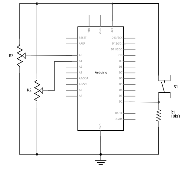
Schematic view of an Arduino attached to two potentiometers and a pushbutton. The potentiometers' center pins are connected to the Arduino's A0 and A1 inputs, respectively.
Figure 9. Schematic view of an Arduino attached to two potentiometers and a pushbutton. The potentiometers’ center pins are connected to the Arduino’s A0 and A1 inputs, respectively. Their left pins are connected to the voltage bus, and the right pins are connected to the ground bus, respectively. The pushbutton is connected from the Arduino’s voltage output to pin D2. a 10-kilohm connects the junction of the switch and pin D2 to ground.
Breadboard view of an Arduino Uno attached to two potentiometers and a pushbutton.
Figure 10. Breadboard view of an Arduino Uno attached to two potentiometers and a pushbutton. The potentiometers’ center pins are connected to the Arduino’s A0 and A1 inputs, respectively. Their left pins are connected to the voltage bus, and the right pins are connected to the ground bus, respectively. The pushbutton is connected from the Arduino’s voltage output to pin D2. a 10-kilohm connects the junction of the switch and pin D2 to ground.

Breadboard view of an Arduino Nano attached to two potentiometers and a pushbutton
Figure 11. Breadboard view of an Arduino Nano attached to two potentiometers and a pushbutton. The potentiometers’ center pins are connected to the Arduino’s A0 and A1 inputs, respectively. Their left pins are connected to the voltage bus, and the right pins are connected to the ground bus, respectively. The pushbutton is connected from the Arduino’s voltage output to pin D2. a 10-kilohm connects the junction of the switch and pin D2 to ground.

(Diagrams made with Fritzing, a circuit design program)


Sending Multiple Serial Data using Punctuation

You’re going to program the microcontroller to read the pushbutton and two analog sensors just like you did in the Intro to Serial Communications Lab. When you have to send multiple data items, you need a way to separate them. If you’re sending them as ASCII-encoded strings, it’s simple: you can just put non-numeric punctuation bytes between them (like a comma or a space) and a unique termination punctuation at the end (like a newline and/or carriage return).

This program will send the two analog sensor values and then the pushbutton. All three will be ASCII-encoded numeric strings, separated by commas. The whole line of sensor values will be terminated by carriage return (\r, ASCII 13) and newline (\n, ASCII 10).

const int buttonPin = 2;      // digital input

void setup() {
  // configure the serial connection:
  Serial.begin(9600);
  // configure the digital input:
  pinMode(buttonPin, INPUT);
}

void loop() {
  // read the first analog sensor:
  int sensorValue = analogRead(A0);
  // print the results:
  Serial.print(sensorValue);
  Serial.print(",");

  // read the second analog sensor:
  sensorValue = analogRead(A1);
  // print the results:
  Serial.print(sensorValue);
  Serial.print(",");

  // read the button:
  sensorValue = digitalRead(buttonPin);
  // print the results:
  Serial.println(sensorValue);
}

When you run this and output it to the Serial Monitor, you should see something like this:

348,363,1
344,362,1
345,363,1
344,375,0
365,374,0
358,369,0
355,369,0
352,373,0
356,373,0

Turn the potentiometers (or tweak the analog sensors) and push the button. Now you’ve got a data format: three sensors, comma-separated, terminated by carriage return and newline. This means that you already have an algorithm for how you’re going to program P5.js to read the serial input:

  • Read the incoming serial data into a string until a carriage return and newline appear
  • split the string into substrings on the commas
  • convert the substrings into numbers
  • assign the numbers to variables to change your programNow that you’ve got a plan, put it into action.

Receive the data in P5.js

Now write a P5.js sketch that reads the data as formatted by the Arduino program above. Download the latest version of the P5.serialcontrol application if you haven’t already and save it in your Applications folder. When you run it, it will check serial ports on your machine. You don’t need to do anything with the app, just have it open.

You’ll need to know the name of your serial port to get started. If you’re not sure how to get this, see the Serial Input to P5.js lab for how to get a list of ports.

The P5.js Sketch

The sketch you’re going to write will control the microcontroller’s LED from P5.js. Dragging the mouse up and down the canvas will dim or brighten the LED, and typing 0 through 9 will set the LED’s brightness in increments from off (0) through almost full brightness (9). There’s an alternate sketch that will make changing tones if you prefer that instead of a changing LED. The sketch will also receive serial input from the microcontroller just as in the Serial Input to P5.js lab, so that you can see that the microcontroller is getting the same values you’re sending.

As you saw in the Serial Input to P5.js lab,  you’ll need to copy the p5.seriaport.js lbrary into your sketch’s libraries folder. You’ll need to run p5.serialcontrol, or run the p5.serialserver from the command line as you did in the Serial Input to P5.js lab as well.

Make a P5.js sketch. If you’re using the p5.js web editor, make a new sketch. Click the Sketch Files tab, and then choose the index.html file. In the head of the document, look for this line:

<script src="https://cdnjs.cloudflare.com/ajax/libs/p5.js/1.4.0/p5.js"></script>

Right after that line, add this line:

<script language="javascript" type="text/javascript" src="https://cdn.jsdelivr.net/npm/p5.serialserver@0.0.28/lib/p5.serialport.js"></script>

The setup of your sketch will initialize the P5.serialport library and define your callback functions for serial events. , as you did in other sketches

Then in the setup(), create a canvas, make an instance of the serialport library, and declare your callback functions.

var serial;          // variable to hold an instance of the serialport library

function setup() {
  createCanvas(800, 600);          // make canvas
  smooth();                        // antialias drawing lines
  serial = new p5.SerialPort();    // make a new instance of the serialport library
  serial.on('list', printList);    // set a callback function for the serialport list event
  serial.on('connected', serverConnected); // callback for connecting to the server
  serial.on('open', portOpen);     // callback for the port opening
  serial.on('data', serialEvent);  // callback for when new data arrives
  serial.on('error', serialError); // callback for errors
  serial.on('close', portClose);   // callback for the port closing

  serial.list();                   // list the serial ports
}

This time, you’ll add a serialport select menu as you did in the Serial Input to P5.js  lab.First, declare a global variable to hold the port menu at the top of your sketch like so:

var portSelector; // a select menu for the port list

Then change the printList function like so:

// get the list of ports:
function printList(portList) {
  // make a select menu and position it:
  portSelector = createSelect();
  portSelector.position(10,10);
  
  // portList is an array of serial port names
  for (var i = 0; i < portList.length; i++) {
    // Display the list the console:
    // console.log(i + " " + portList[i]);
    // add item to the select menu:
    portSelector.option(portList[i]);
  }
  // set a handler for when a port is selected from the menu:
  portSelector.changed(mySelectEvent);
}

When the select menu’s value has changed, you can assume a serial port has been selected, so write a handler to open it like so:

function mySelectEvent() {
  let item = portSelector.value();
   // if there's a port open, close it:
  if (serial.serialport != null) {
    serial.close();
  }
  // open the new port:
  serial.open(item);
}

From now on, when you run this sketch, you’ll need to select the serial port to open the port.

The rest of the serial event handlers are all the same as you saw in the P5.js Serial Input Lab, except for the serialEvent(). Here are all but the serialEvent():

function serverConnected() {
  console.log('connected to server.');
}

function portOpen() {
  console.log('the serial port opened.')
}

function serialError(err) {
  console.log('Something went wrong with the serial port. ' + err);
}

function portClose() {
 console.log('The serial port closed.');
}

Program the serialEvent() function to read the incoming serial data as a string until it encounters a carriage return and newline (‘\r\n’). Then check to see that the resulting string has a length greater than 0 bytes. If it does, use the split() function to split it in to an array of strings. If the resulting array is at least three elements long, you have your three sensor readings. The first reading is the first analog sensor, and can be mapped to the horizontal movement using the locH variable. The second is the second analog sensor and can be mapped to the locV variable. The third is the button. When it’s 0, set the circleColor variable equal to 255 and when it’s 1, set the variable to 0. Here’s how:

function serialEvent() {
  // read a string from the serial port
  // until you get carriage return and newline:
  var inString = serial.readStringUntil('\r\n');

  //check to see that there's actually a string there:
  if (inString.length > 0 ) {
    var sensors = split(inString, ',');            // split the string on the commas
    if (sensors.length > 2) {                      // if there are three elements
      locH = map(sensors[0], 0, 1023, 0, width);   // element 0 is the locH
      locV = map(sensors[1], 0, 1023, 0, height); // element 1 is the locV
      circleColor = 255 - (sensors[2] * 255);      // element 2 is the button
    }
  }
}

Note the mappings of sensor[0] and sensor[1]. You should use the input mappings for your accelerometer instead of 0 and 1023. If your analog values are greater than the width of the sketch or the height, the circle will be offscreen, which is why you have to map your sensor range to the screen size.

Program the draw() function to draw a circle that’s dependent on three global variables, locH, locV, and circleColor. Add these three globals to the top of the program:

var locH = 0;
var locV = 0;        // location of the circle
var circleColor = 255; // color of the circle

Finally, here is the draw function:

function draw() {
  background(0);               // black background
  fill(circleColor);           // fill depends on the button
  ellipse(locH, locV, 50, 50); // draw the circle
}

If you run this, you should see the circle moving onscreen whenever you tilt the accelerometer. When you press the pushbutton, the circle will disappear. Okay, it’s not exactly a  mouse, but you are controlling an animation from a device that you built.

Flow Control: Call and Response (Handshaking)

You’ve seen now that by coming up with a serial format (called a protocol), you can write the algorithm for receiving it even before you see any data. You can send multiple pieces of data this way, as long as you format it consistently.

Sometimes you can run into a problem when the sender sends faster than the receiver can read. When this happens, the receiver program slows down as the serial buffer fills up. You can manage this by implementing some form of flow control. The simplest way do to this is using a call-and-response method, where the sending program only sends when it’s told to do so, and the receiving program has to request new data every time it finishes reading what it’s got.

You can add handshaking to the code above fairly simply. Modify the Arduino code as follows. First, add a a new block of code in the setup() This block sends out a message until it gets a byte of data from the remote computer:

void setup() {
  Serial.begin(9600);
  while (Serial.available() <= 0) {
    Serial.println("hello"); // send a starting message
    delay(300);              // wait 1/3 second
  }
}

Now, modify the loop() by adding an if() statement to look for incoming serial data and read it.

void loop() {
  if (Serial.available() > 0) {
    // read the incoming byte:
    int inByte = Serial.read();
    // read the sensor:
    sensorValue = analogRead(A0);
    // print the results:
    Serial.print(sensorValue);
    Serial.print(",");

    // read the sensor:
    sensorValue = analogRead(A1);
    // print the results:
    Serial.print(sensorValue);
    Serial.print(",");

    // read the sensor:
    sensorValue = digitalRead(buttonPin);
    // print the results:
    Serial.println(sensorValue);
  }
}

The rest of the sketch remains the same. When you run this and open the serial monitor, you’ll see:

hello
hello
hello
hello

Type any character in the output box and click Send. You’ll get a string of sensor values at the end of your hellos:

510,497,0

Type another character and click Send. It doesn’t matter what character you send, but the loop will always wait for an incoming byte before sending a new set of sensor values. When you write a program to receive this format, it just has to behave the same way you did:

  • Open the serial port
  • Wait for a Hello
  • Send a byte to request data
  • Begin loop:
  • Wait for one set of data
  • Send a byte to request new data
  • end loop

Next, modify the P5.js sketch.  Most of the changes are in the serialEvent() function. The initial “hello” messages will trigger this function, so when you get a “hello” or any other string, you need to send a byte back so that the Arduino has a byte available to read. Here’s the new serialEvent():

function serialEvent() {
  // read a string from the serial port
  // until you get carriage return and newline:
  var inString = serial.readStringUntil('\r\n');
  //check to see that there's actually a string there:
  if (inString.length > 0) {
    if (inString !== 'hello') { // if you get hello, ignore it
      var sensors = split(inString, ','); // split the string on the commas
      if (sensors.length > 2) { // if there are three elements
        locH = map(sensors[0], 0, 1023, 0, width); // element 0 is the locH
        locV = map(sensors[1], 0, 1023, 0, height); // element 1 is the locV
        circleColor = 255 - (sensors[2] * 255); // element 2 is the button
      }
    }
    serial.write('x'); // send a byte requesting more serial data
  }
}

You also need to add a line to the openPort() function like so:

function portOpen() {
  console.log('the serial port opened.')
  // send a byte to prompt the microcontroller to send:
  serial.write('x');
}

The reason for this is that if your Arduino has already broken out of the loop (let’s say you opened the Serial monitor to check), then it is waiting for a byte from p5.js to send the next block of code. By sending a byte when you know the port has just been opened in p5.js, you force the Arduino to send you new data.

That’s it. Your sketch should still run just as it did before, though the serial communication is managed better now, because Arduino’s only sending when P5.js is ready to receive.

The full code for all the examples in this lab can be found in this gitHub repository.

Advantages of Raw Binary vs. ASCII

All the examples shown here sent the sensor values as ASCII-encoded strings. As mentioned above, that means you sent three bytes to send a three-digit value. If that same value was less than 255, you could send it in one raw binary byte. So ASCII is definitely less efficient. However, it’s more readable for debugging purposes, and if the receiving program is well-suited to convert strings to numbers, then ASCII is a good way to go. If the receiver’s not so good at converting strings to numbers (for example, it’s more challenging to read a multiple byte string in Arduino than in Processing) then you may want to send your data as binary values.

Advantages of Punctuation or Call-and-Response

The punctuation method for sending multiple serial values may seem simpler, but it has its limitations. You can’t easily use it to send binary values, because you need to have a byte with a unique value for the punctuation. In the example above, you’re using the value 10 (ASCII newline) as punctuation, so if you were sending your sensor values as raw bytes, you’d be in trouble when the sensor’s value is 10. The receiver would interpret the 10 as punctuation, not as a sensor value. In contrast, call-and-response can be used whether you’re sending data as raw binary values or as ASCII-encoded values.

Sometimes the receiver reads serial data slower than the sender sends it. For example, if you have a program that does a lot of graphic work, it may only read serial data every few milliseconds. The serial buffer will get full in that case, you’ll notice a lag in response time. This is when it’s good to switch to a call-and-response method.

Build an Application of Your Own

You just duplicated the basic functionality of a mouse; that is, a device with two analog sensors that affect X and Y, and a digital sensor (mouse button). What applications can you think of that could use a better physical interface for a mouse? A video editor that scrubs forward and back when you tilt a wand? An action game that reacts to how hard you hit a punching bag? An instructional presentation that speeds up if you shift in your chair too much? A music program driven by a custom musical instrument that you design?

Create a prototype in Arduino and P5.js, Node.js, Processing, or whatever programming environment you choose. Come up with a physical interface that makes it clear what actions map to what movements and actions. Figure out which actions can and should be possible at the same time. Present a working software and hardware model of your idea.
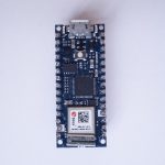
Lab: Serial Input to P5.js Using the p5.serialport library

n this lab, you’ll generate an analog output value from a potentiometer, then send that value via asynchronous serial communication to P5.js. You’ll use that value in P5.js to draw a graph.

Overview

In this lab, you’ll generate an analog output value from a potentiometer, then send that value via asynchronous serial communication to P5.js. You’ll use that value in P5.js to draw a graph.

Serial communication to a web page in a browser isn’t something you see every day. Web browsers don’t usually have access to a computer’s serial ports. In order to get your browser-based applications to communicate with a microcontroller serially, you need a program that can both serve HTML/JavaScript pages, and communicate with the serial port. When you’re making projects with P5.js, you can achieve this by using the P5.serialport library and the P5.serialcontrol app by Shawn Van Every (updated by Jiwon Shin). When you use the p5.serialport library, it communicates with the p5.serialcontrol app, a WebSocket server that gives you access to serial devices attached to your computer. This lab shows you how to do that. 

To get the most out of this tutorial, you should know what a microcontroller is and how to program them. You should also understand asynchronous serial communication between microcontrollers and personal computers. You should also understand the basics of P5.js. This video on serial from Arduino to p5.js may be useful.

Things You’ll Need

For this lab, you’ll need the hardware below, and you’ll need to create a p5.js sketch. You’ll also use the p5.seri alport library and the P5.serialcontrol app. You can use the p5.js web editor or your favorite text editor for this (the Visual Studio Code editor or the  Atom text editor work well).

Figures 1-4 below show the parts you’ll need for this exercise. Click on any image for a larger view.

Photo of an Arduino Nano 33 IoT module. The USB connector is at the top of the image, and the physical pins are numbered in a U-shape from top left to bottom left, then from bottom right to top right.
Figure 1. Microcontroller. Shown here is an Arduino Nano 33 IoT
Photo of flexible jumper wires
Figure 2. Jumper wires.  You can also use pre-cut solid-core jumper wires.
Photo of a solderless breadboard
Figure 3. A solderless breadboard
Photo of two potentiometers
Figure 4. Potentiometer

Prepare the Breadboard

For this exercise you’re going to attach a potentiometer as an analog input to your microcontroller, and send the sensor’s reading serially to p5.js via the p5.serialcontrol app.

Connect power and ground on the breadboard to the microcontroller. On the Arduino module, use the 5V or 3.3V (depending on your model) and any of the ground connections. Figures 5 and 6 show connections for an Arduino Uno and a Nano, respectively.

An Arduino Uno on the left connected to a solderless breadboard, right. The Uno's 5V output hole is connected to the red column of holes on the far left side of the breadboard. The Uno's ground hole is connected to the blue column on the left of the board. The red and blue columns on the left of the breadboard are connected to the red and blue columns on the right side of the breadboard with red and black wires, respectively. These columns on the side of a breadboard are commonly called the buses. The red line is the voltage bus, and the black or blue line is the ground bus.
Figure 5. An Arduino Uno on the left connected to a solderless breadboard, right.

The Uno’s 5V output hole is connected to the red column of holes on the far left side of the breadboard (Figure 5). The Uno’s ground hole is connected to the blue column on the left of the board. The red and blue columns on the left of the breadboard are connected to the red and blue columns on the right side of the breadboard with red and black wires, respectively. These columns on the side of a breadboard are commonly called the buses. The red line is the voltage bus, and the black or blue line is the ground bus.


Arduino Nano on a breadboard.
Figure 6. Breadboard view of an Arduino Nano mounted on a breadboard.

Images made with Fritzing, a circuit drawing application

The Nano is mounted at the top of the breadboard (Figure 6), straddling the center divide, with its USB connector facing up. The top pins of the Nano are in row 1 of the breadboard.

The Nano, like all Dual-Inline Package (DIP) modules, has its physical pins numbered in a U shape, from top left to bottom left, to bottom right to top right. The Nano’s 3.3V pin (physical pin 2) is connected to the left side red column of the breadboard. The Nano’s GND pin (physical pin 14) is connected to the left side black column. These columns on the side of a breadboard are commonly called the buses. The red line is the voltage bus, and the black or blue line is the ground bus. The blue columns (ground buses) are connected together at the bottom of the breadboard with a black wire. The red columns (voltage buses) are connected together at the bottom of the breadboard with a red wire.


Add a Potentiometer

Connect a potentiometer to analog in pin 0 of the module. Figure 7 shows the schematic and figures 8 and 9 show the potentiometer connected to an Arduino and Nano, respectively.

Schematic view of a potentiometer. First leg of the potentiometer is connected to +5 volts. The second leg connected to analog in 0 of the Arduino. The third leg is connected to ground.
Figure 7. Schematic view of a potentiometer connected to analog in 0 of the Arduino
Breadboard view of a potentiometer. First leg of the potentiometer is connected to +5 volts. The second leg connected to analog in 0 of the Arduino. The third leg is connected to ground.
Figure 8. Breadboard view of a potentiometer connected to analog in 0 of an Arduino. The potentiometer is connected to three rows in the left center section of the breadboard. The two outside pins are connected to voltage and ground. The center pin is connected to the Arduino’s analog in 0.

Breadboard view of Arduino Nano with an potentiometer input.
Figure 9. Breadboard view of a potentiometer connected to analog in 0 of an Arduino Nano. The Nano is connected as usual, straddling the first fifteen rows of the breadboard with the USB connector facing up. Voltage (physical pin 2) is connected to the breadboard’s voltage bus, and ground (physical pin 14) is connected to the breadboard’s ground bus. The potentiometer is connected to three rows in the left center section of the breadboard. The two outside pins are connected to voltage and ground. The center pin is connected to the Nano’s analog in 0.

Program the Microcontroller

Program your Arduino to read the analog input as follows:

void setup() {
  Serial.begin(9600); // initialize serial communications
}

void loop() {
  // read the input pin:
  int potentiometer = analogRead(A0);                  
  // remap the pot value to fit in 1 byte:
  int mappedPot = map(potentiometer, 0, 1023, 0, 255); 
  // print it out the serial port:
  Serial.write(mappedPot);                             
  // slight delay to stabilize the ADC:
  delay(1);                                            
}

The P5.js Serialport Library

To communicate with your microcontroller serially, you’re going to use the P5.js serialport library and the p5.serialcontrol app. The P5.js serialport library can’t access your serial ports directly when a sketch is running in a browser because the browser doesn’t have direct access to the serial port. But it can communicate with another program on your computer that can exchange data with the serialport. p5.serialcontrol is  the app that connects your sketch, running in a browser, with the serial ports on your computer as shown in Figure 10.

Diagram of three rectangles connected by arrows. The rectangle on the right represents your p5.js sketch, running in a browser. Your sketch implements the p5.serialport library. Your sketch connects to p5 serial control, the middle rectangle, via a webSocket. The p5 serial control application runs on your laptop. It connects to a serial port on your computer and listens for webSocket connections from your p5.js sketch. It passes whatever comes in the serial port through to the webSocket and vice versa. The third rectangle is your Arduino, connected to p5 serial control via the serial port.
Figure 10. Diagram of the connection from the serial port to p5.js through p5.serialcontrol

Once you gain an understanding of serial communication, you can use any program that can connect with your computer’s serial ports to communicate with a microcontroller. Processing, Max/MSP, and OpenFrameworks are three other popular multimedia programming environments that can communicate via the serial ports. You can also do this with Unity, Unreal, or any other programming environment that can access the serial ports.

Install the p5.Serialcontrol App

Download the latest version of the P5.serialcontrol application and save it in your Applications folder. When you run it, it will check serial ports on your machine. You don’t need to do anything with the app, just have it open. However, remember this most important fact:

Only one port at a time can access a serial port.

That means that when you want to reprogram your Arduino from the Arduino IDE, you need to quit p5.serialcontrol to do so. Then, reopen p5.serialcontrol when you’re done reprogramming the Arduino. You don’t need to quit the Arduino IDE each time, because it knows to release the serial port when it’s not programming. However, you do need to close the Serial Monitor in the Arduino IDE when you are using p5.serialcontrol.

Program P5.js to List the Available Serial Ports

Now you’re ready to make a P5.js sketch. If you’re using the p5.js web editor, make a new sketch. Click the Sketch Files tab, and then choose the index.html file. In the head of the document, look for this line:

<script src="https://cdnjs.cloudflare.com/ajax/libs/p5.js/1.4.0/p5.js"></script>

Right after that line, add this line:

<script language="javascript" type="text/javascript" src="https://cdn.jsdelivr.net/npm/p5.serialserver@0.0.28/lib/p5.serialport.js"></script>

The p5.js Sketch

To start off, your programming environment needs to know what serial ports are available in the operating system. Open the sketch.js file and change it to the following:

let serial; // variable to hold an instance of the serialport library

function setup() {
  serial = new p5.SerialPort(); // make a new instance of the serialport library
  serial.on('list', printList); // set a callback function for the serialport list event

  serial.list(); // list the serial ports
}

// get the list of ports:
function printList(portList) {
  // portList is an array of serial port names
  for (var i = 0; i < portList.length; i++) {
    // Display the list the console:
    console.log(i + portList[i]);
  }
}

When you run this p5.js sketch in a browser, you’ll get a list of the available serial ports in the console. This list will look just like the list of serial ports you see in the Arduino Tools menu. Find the name of your port in the list. Later, you’ll assign that name to a global variable called portName.

Now you’re ready to listen for some incoming serial data.

 Serial Events

JavaScript, the language on which p5.js is based, relies heavily on events and callback functions. An event is generated by the operating system when something significant happens, like a serial port opening, or new data arriving in the port. In your sketch, you write a callback function to respond to that event. The serialport library uses events and callback functions as well. It can listen for the following serialport events:

  • list – the program asks for a list of ports.
  • connected – when the sketch connects to a webSocket-to-serial server
  • open – a serial port is opened
  • close – a serial port is closed
  • data – new data arrives in a serial port
  • error – something goes wrong.

You’re already using a callback for the ‘list’ event in the code above. You set a callback for the ‘list’ event, then you called it with serial.list(). Generally, you should set your callbacks before you use them like this.

To use the rest of the serialport library’s events, you need to set callback functions for them as well. Add a new global variable called portName and initialize it with the name of your serial port that you got from the listPorts() function before. Then change your setup() function to include callbacks for open, close, and error like so:

let serial;          // variable to hold an instance of the serialport library
let portName = '/dev/cu.usbmodem1421';  // fill in your serial port name here

function setup() {
  serial = new p5.SerialPort();       // make a new instance of the serialport library
  serial.on('list', printList);  // set a callback function for the serialport list event
  serial.on('connected', serverConnected); // callback for connecting to the server
  serial.on('open', portOpen);        // callback for the port opening
  serial.on('data', serialEvent);     // callback for when new data arrives
  serial.on('error', serialError);    // callback for errors
  serial.on('close', portClose);      // callback for the port closing

  serial.list();                      // list the serial ports
  serial.open(portName);              // open a serial port
}

Notice the final line of the setup(). It’s going to generate an ‘open’ event, which will be handled by a function called portOpen().

Wait a Minute! Don’t I have to Set the Data Rate When I Open the Port?

In asynchronous serial communications, both computers have to set the same data rate in order to communicate. In Arduino, you set the data rate with Serial.begin(9600); In p5.js, 9600 bits per second is the default, so you don’t have to set the rate if you want 9600bps. But if you want to set the rate to another value, do it like this:

let options = { baudrate: 9600}; // change the data rate to whatever you wish
serial.open(portName, options);

Now add new functions to respond to the callbacks you just declared. These come after your setup() function:

function serverConnected() {
  console.log('connected to server.');
}

function portOpen() {
  console.log('the serial port opened.')
}

function serialEvent() {

}

function serialError(err) {
  console.log('Something went wrong with the serial port. ' + err);
}

function portClose() {
  console.log('The serial port closed.');
}

The function that matters the most, though, is serialEvent(), the one that responds to new data. Each time a new byte arrives in the serial port, this function is called. Now it’s time to make serialEvent() do some work. Add a new global variable at the top of your sketch called inData like so:

let serial;          // variable to hold an instance of the serialport library
let portName = '/dev/cu.usbmodem1421';  // fill in your serial port name here
let inData;                             // for incoming serial data

Then modify the serialEvent() function like so:

function serialEvent() {
  inData = Number(serial.read());
}

Next, make the draw() function to print the sensor value to the screen. Start by adding a createCanvas() call to the top of your setup() like so:

function setup() {
createCanvas(400, 300);

Then here’s your draw() function:

function draw() {
   background(0);
   fill(255);
   text("sensor value: " + inData, 30, 50);
}
A screenshot of the sketch running in a browser.
Figure 13. A screenshot of the sketch running in a browser. The sketch prints the sensor value in text on the screen.

When you run your sketch now, you should get something like the sketch shown in Figure 13.

The sensor value onscreen should change as you turn your potentiometer. Congratulations! You’ve got P5.js talking to your microcontroller.

What’s Happening Here

Every time your microcontroller sends a byte serially using Serial.write(), the computer receives it and generates a ‘data’ event. Then your serialEvent() function is called. It reads the byte as a number, and stores it in the global variable inData. The draw() method just uses the latest value of inData in the text string it displays on the screen.

You may be wondering why you’re mapping the sensor value or dividing it by 4 in the Arduino sketch above. That’s because in order to send the sensor value as a single byte, it must be between 0 and 255, or no more than 28 bits.

P5.js Console.log() and Arduino delay(): a Tricky Combination

In testing this, you may have put a console.log() statement in the serialEvent() function in your P5.js sketch. When you did, you would have noticed that it causes a lag in the sketch, and the console.log() statements continue even after you stop the sketch. This is because the operating system keeps the incoming serial data in a buffer, and P5.js isn’t reading and printing it as fast as Arduino is sending it.

You might think, “Okay, then I’ll just put a delay() in my Arduino sketch to slow it down.” That’s a bad idea. When you put in a delay, it means you’re only reading your sensor when that delay is not running.  You can miss critical sensor events while that delay is in progress. Even a relatively small delay, for example 30ms, can make it difficult to reliably read state changes in a switch or peaks in an analog sensor. Don’t use delays if you can avoid it. For more on how to handle the flow of serial data from Arduino to P5.js and back, see the Duplex Serial Flow in P5.js lab.

Adding A Serial Port Select Menu

If you don’t want to have to remember the serial port name every time you run the sketch, you can add a drop-down menu to select the port. Add a global variable at the top of your sketch called portSelector like so:

// HTML Select option object:
let portSelector;

Then replace the printList() function with the following:

// make a serial port selector object:
function printList(portList) {
  // create a select object:
  portSelector = createSelect();
  portSelector.position(10, 10);
  // portList is an array of serial port names
  for (var i = 0; i < portList.length; i++) {
    // add this port name to the select object:
    portSelector.option(portList[i]);
  }
  // set an event listener for when the port is changed:
  portSelector.changed(mySelectEvent);
}

Then add an extra function that will get called when the port list is changed. This function will get the name of the port you select, close any port that’s open, and open the port you asked for:

function mySelectEvent() {
  let item = portSelector.value();
   // if there's a port open, close it:
  if (serial.serialport != null) {
    serial.close();
  }
  // open the new port:
  serial.open(item);
}

If you choose this approach, you can delete the global portName variable at the top of your sketch, and the line in your setup() that says:

 serial.open(portName);              // open a serial port

Instead of opening the serial port once at the beginning of your code, you’re now opening and closing the port every time you select from this menu.

Draw a Graph With the Sensor Values

It would be useful to see a graph of the sensor values over time. You can do that by modifying the draw() method to draw the graph. To do this, add a new global variable at the top of your sketch called xPos. You’ll use this to keep track of the x position of the latest graph line:

let xPos = 0;                     // x position of the graph

Because of the way the graphing function below works, you can’t reset the background every time through the draw() loop. So take the background() command and put it in the setup() function instead of the draw(), as shown below. That way it runs once, then not again. As long as you’re at it, switch from black & white to a nice blue color:

function setup() {
  createCanvas(400, 300);
  background(0x08, 0x16, 0x40);

Now make a new function called graphData(). It’ll take a number value as a parameter, and it will draw a line on the screen that’s mapped to the number value. Then it will increment xPos so that the next line is drawn further along. It will also check if the xPos is at the right edge of the screen, and reset the screen by calling background() again if it is:

function graphData(newData) {
  // map the range of the input to the window height:
  var yPos = map(newData, 0, 255, 0, height);
  // draw the line in a pretty color:
  stroke(0xA8, 0xD9, 0xA7);
  line(xPos, height, xPos, height - yPos);
  // at the edge of the screen, go back to the beginning:
  if (xPos >= width) {
    xPos = 0;
    // clear the screen by resetting the background:
    background(0x08, 0x16, 0x40);
  } else {
    // increment the horizontal position for the next reading:
    xPos++;
  }
}

Finally, take everything out of the draw() function and just call graphData() from there:

function draw() {
  graphData(inData);
}

When you run the sketch now, you should get a graph, as shown in Figure 14.

Screenshot of the serial graph p5.js sketch.
Figure 14. Screenshot of the serial graph p5.js sketch. The sensor’s values are graphed on the screen

If you’d like to see a fancier graphing sketch, check out this sketch, which adds chart.js to make a better graph. Chart.js is a great tool for graphing data in JavaScript, and it integrates well with p5.js.

Reading Serial Data as a String

This works well if you want to read your sensor values as a single byte, but what if you want a larger range of numbers?  What if you want the full 0 to 1023 that analogRead() can output instead of just 0 to 255?  To do this, you need to send the data as an ASCII-encoded numeric string from the microcontroller, and you need to read and interpret the incoming data in P5 as an ASCII-encoded numeric string as well.

Change your Arduino program to the following:

void setup() {
 Serial.begin(9600); // initialize serial communications
}

void loop() {
 int potentiometer = analogRead(A0);                  // read the input pin
 int mappedPot = map(potentiometer, 0, 1023, 0, 255); // remap the pot value to fit in 1 byte
 Serial.println(mappedPot);                           // print it out the serial port
 delay(1);                                            // slight delay to stabilize the ADC
}

Now it will print the potentiometer’s value as an ASCII-encoded numeric string, and it will add a carriage return byte and a newline byte at the end, because that’s what println() does.

Once you’ve uploaded this to your Arduino, run your P5 sketch again. Try adding println(inData); at the end of your serialEvent() function. When your P5 sketch reads the data from this Arduino program, you get very low values, and every so often you see the value 10 followed by the value 13. What’s going on?

When a computer ASCII-encodes a number, it converts that number to a string of bytes, each of which is the ASCII value for a numeral in the number. For example, the number 865 gets converted to three bytes, as shown in Figure 15.

ASCII representation of a three-digit number.
Figure 15. The decimal number 865 when sent serially as ASCII is three bytes long. The first byte representing digit, 8, has the ASCII value 58. The second byte representing the digit 6 has the ASCII value 54. The third byte representing the digit 5 has the ASCII value 53.

If there’s a carriage return byte and a newline byte after this, the string is five bytes, and the last two bytes’ values are 13 (carriage return, or \r in most programming languages) and 10 (newline or \n in most programming languages), respectively.

Your P5.js sketch is reading every byte’s value and graphing it. That’s why you get a graph of very low values, with a bunch of them being 13 and 10. The Arduino is ASCII-encoding the potentiometer values, but the P5 sketch is interpreting the bytes as if they’re not encoded that way.

Now change the serialEvent() function like so:

function serialEvent() {
  // read a byte from the serial port, convert it to a number:
  inData = serial.readLine();
}

Run it again. What’s changed? Now you’re getting a graph kind of like you were before. The serial.readLine(); command reads the incoming serial data as a string, and when that string happens to be all-numeric, it converts it to a number. So you’re getting the ASCII-encoded string as a number again. But now there are gaps. Why?

Remember, the ‘data’ event occurs every time a new byte comes in the serial port. Now that you’re sending an ASCII-encoded string, every potentiometer reading is several bytes long. So you only get a complete string every three to six bytes (three for “0\r\n” and six for “1023\r\n”). Sometimes, when the serialEvent() function calls serial.readLine(); it gets nothing. That’s when draw() draws the gaps. You need to change your function to check that the resulting string is actually a valid number before you put the string into inData. First, create a local variable to get the string, then check to see if the string’s length is greater than zero. If it is, then put it into inData so that the other functions in the sketch can use the new data. Here’s how you do that:

function serialEvent() {
  // read a string from the serial port:
  var inString = serial.readLine();
  // check to see that there's actually a string there:
  if (inString.length > 0 ) {
  // convert it to a number:
  inData = Number(inString);
  }
}

Here is a link to the complete serial in p5.js sketch.

Now you’re able to send in a number of any value to P5.js. You don’t have to limit your input to a 0-255 value range. See if you can modify the Arduino sketch and the P5.js sketch to exchange a potentiometer value that spans the whole range from 0 to 1023.

note: readLine() is the same as readStringUntil(‘\r\n’);

The full code for all the examples in this lab can be found in this gitHub repository.

Optional: Accessing a Serial Sketch From Another Computer

You know that p5.js can run in any browser, but what happens to a sketch using p5.serialport.js when it’s running on someone else’s computer, or on your phone or tablet? What serial port does it connect to? That depends on what you do when you initialize it.

When you call new p5.SerialPort() with no parameter between the parentheses, the library attempts to connect to p5.serialcontrol app on the computer that’s running the sketch. If you’re running the sketch on your laptop’s browser, then the library connects to the your laptop’s ports through p5.serialcontrol. But imagine you run the sketch on your phone, but you want the sketch to connect to an Arduino connected to a serial port on your laptop. To do this, the your laptop has to be the web host for your sketch, as well as the computer running p5.serialcontrol. In addition, your laptop and the device running the sketch have to be on the same local network.

note: this will not work if your sketch is in the p5.js web editor. You’ll need to download the sketch and edit it on your laptop to make it work.

Launch the p5.serialcontrol app. It will display the IP address of the computer on which it’s running. Copy it, and modify the new p5.SerialPort() line at the beginning of your setup() function, adding the IP address like so:

serial = new p5.SerialPort('10.17.34.128'); // fill in your own IP address in place of the one shown here

Save the sketch, then open a command line interface on your computer (the Terminal app in MacOS, for example). Change directories to the directory where your sketch lives (for example, cd ~/Documents/p5_sketches/mySerialSketch) and run a simple web server like so:

$ python -m SimpleHTTPServer 8080

Now open a browser, either on your computer or your phone or tablet, and enter the following address:

http://your.ip.address:8080

To close this server, type control-C. You can modify the sketch as much as you want, and reload it in the browser without having to re-start the server.

The sketch should run, and operate just as you saw earlier. This approach is handy if you want to use a tablet or phone as a multimedia device to control sounds or videos, controlled by physical sensors on a microcontroller.

Note: the IP address of your computer will change as you move from one network to another (for example, from school to home). If you want to get the IP address dynamically, you can use this: window.location.hostname. This will always return the address of the host computer that served the webpage. So, for example, changing the line above to read as follows will automatically adjust the hostname each time.

// use the hostname of the computer that served this page:
serial = new p5.SerialPort(window.location.hostname); 

For more detail on this, see the video Screens: Communicating from a mobile device to a microcontroller using p5.js serialControl.

Conclusion

In this lab, you saw how to connect an Arduino microcontroller to a P5.js sketch using a webSocket-to-serial server, P5.serialserver, and the P5.serialport library. You sent data from Arduino to the sketch as a raw binary value — that is, a single byte ranging from 0 to 255 — and you sent it as an ASCII-encoded numeric string with a carriage return and newline at the end. See Table 1 below to review what are suitable data formats for different types/sizes of data and which functions to use on p5.js and Arduino for serial communication.

Data to Send
A single value
within 0-255
(< 2^8 = 1 byte)
Larger numbers & characters in Ascii Table,
Multiple values
Send as:
Binary
Ascii
Arduino ->
Serial.write()
Serial.println()
-> p5.js
serial.read()
serial.readLine()
=readStringUntil('\r\n')

Table 1. Serial Communication: Arduino to p5.js

Notes about sending Ascii data:

  • Using Serial.println() on Arduino and serial.readLine() on p5.js is one of many different ways of sending Ascii data from Arduino to p5.js with serial communication.
  • If you want to use the value as a numeric value not a string, convert the value into number by using Number(). 

Understanding the difference between ASCII-encoded strings and raw binary data is central to all serial communications. For more examples of this in action, see the Serial Output from P5.js lab.