The videos linked from this page describe specific forms of output, or actuators.
Intro to programmable LEDs: NeoPixels (worldSemi WS2812):
Color spaces in programmable LEDS:
The videos linked from this page describe specific forms of output, or actuators.
Intro to programmable LEDs: NeoPixels (worldSemi WS2812):
Color spaces in programmable LEDS:
In this lab you’ll learn how to send data from p5.js to a microcontroller using asynchronous serial communication.
In this lab you’ll learn how to send data from p5.js to a microcontroller using asynchronous serial communication.
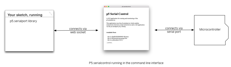
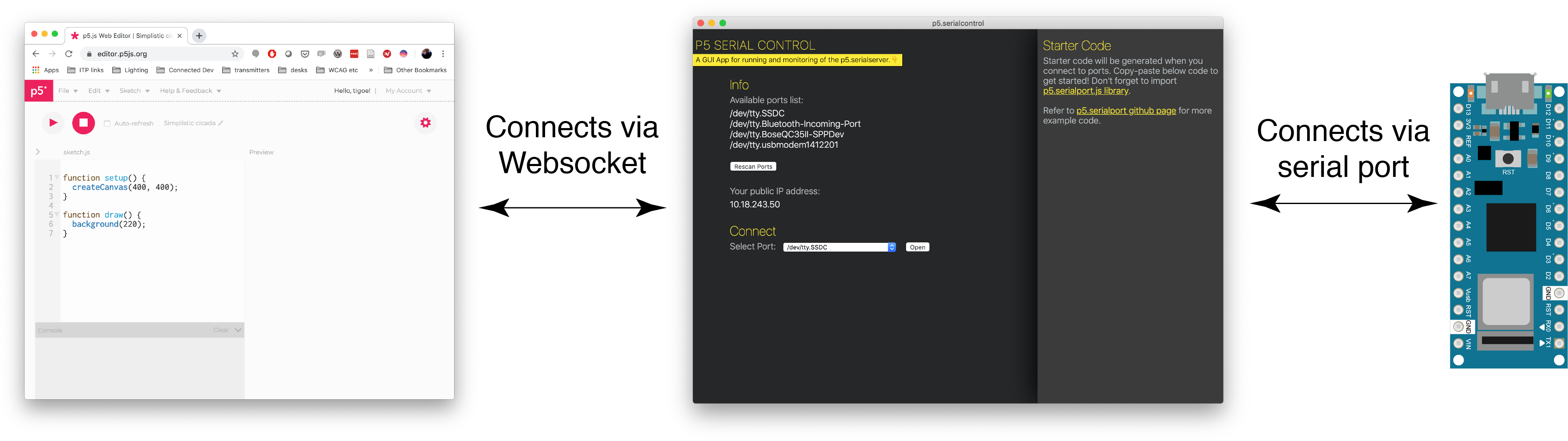
When you use the p5.serialport library for P5.js, it communicates with a webSocket server in the P5.js IDE to give you access to serial devices attached to your computer. This lab shows you how to use P5 to control a microcontroller using asynchronous serial communication.
To get the most out of this tutorial, you should know what a microcontroller is and how to program them. You should also understand asynchronous serial communication between microcontrollers and personal computers. You should also understand the basics of P5.js, and should have tried the Serial Input to P5.js lab.
For this lab, you’ll need the hardware below,
For this lab, you’ll need the hardware below, and you’ll need the same software setup as the Serial Input to P5.js lab: You’ll create a p5.js sketch. You’ll also use the p5.serialport library and the P5.serialcontrol app. You can use the p5.js web editor or your favorite text editor for this (the Visual Studio Code editor or the Atom text editor work well).


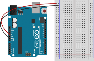
Connect power and ground on the breadboard to power and ground from the microcontroller. On the Arduino UNo, use the 5V and any of the ground connections. On the Nano, use 3.3V and the ground connections:

The +3.3 volts and ground pins of the Arduino Nano are connected by red and black wires(Figure 6), respectively, to the left side rows of the breadboard. +3.3 volts is connected to the left outer side row (the voltage bus) and ground is connected to the left inner side row (the ground bus). The side rows on the left are connected to the side rows on the right using red and black wires, respectively, creating a voltage bus and a ground bus on both sides of the board.Figure 5. Breadboard view of an Arduino Nano connected to a breadboard. The +3.3 volts and ground pins of the Arduino are connected by red and black wires, respectively, to the left side rows of the breadboard. +3.3 volts is connected to the left outer side row (the voltage bus) and ground is connected to the left inner side row (the ground bus). The side rows on the left are connected to the side rows on the right using red and black wires, respectively, creating a voltage bus and a ground bus on both sides of the board.
Made with Fritzing
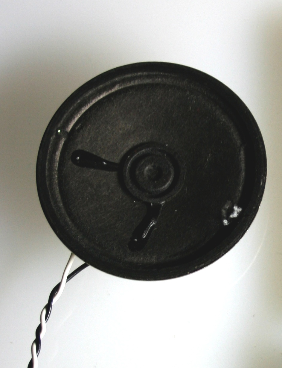
Connect the LED and resistor to digital I/O pin 11 of the module(Figure 7-8). Alternately, you can replace the 220-ohm LED with a speaker (Figure 9-10). You’ll find code below that uses tones instead of LEDs where appropriate. For more on how to do that, see the Tone Output lab:
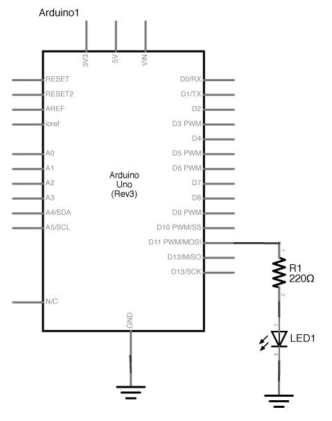
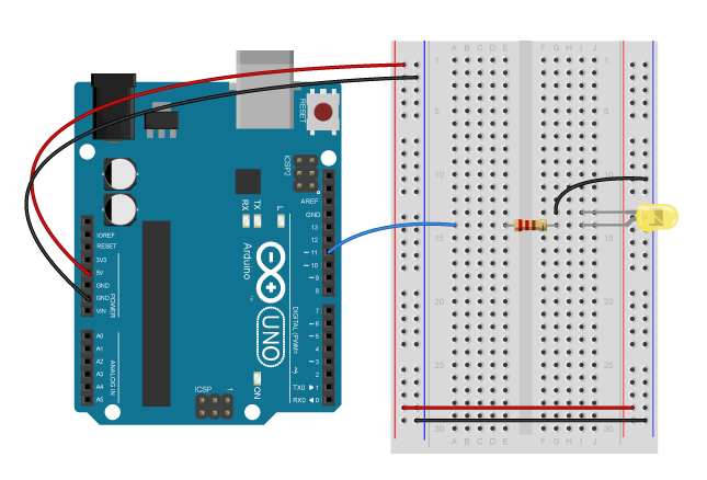
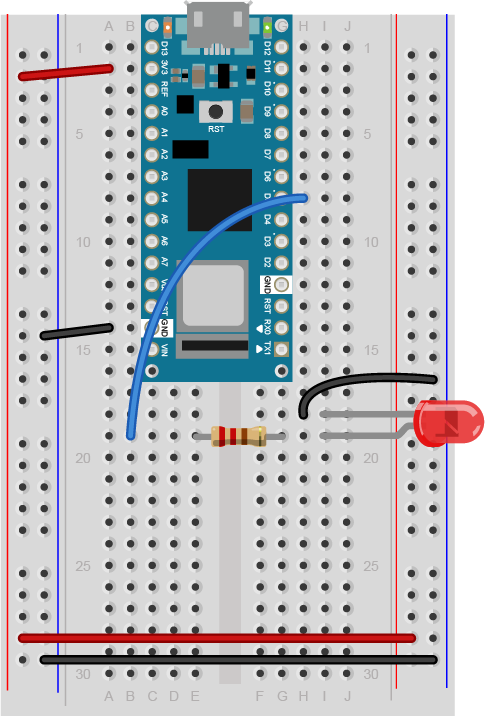
Figure 9 shows a breadboard view of an LED connected to digital pin 5 of an Arduino Nano. The Nano straddles the center of the breadboard in the first fifteen rows. The Nano’s voltage pin (physical pin 2) connects to the board’s voltage bus, and the Nano’s ground pin (physical pin 14) connects to the board’s ground bus. The LED is in the right center of the board, with its anode in one row and the cathode in the next. A 220-ohm resistor connects the LED’s anode to a wire connecting to digital pin 5. The LED’s cathode is connected to the ground bus.
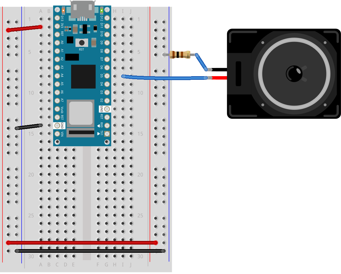
Figure 10 shows a breadboard view of an Arduino Nano connected to a speaker. The Nano’s ground (physical pin 14) is connected to the ground bus of the breadboard as usual. The red positive wire of the speaker is connected to digital pin 5 of the Arduino. The black ground wire of the speaker is connected to one leg of a 100 ohm resistor. The other leg of the resistor connects to ground.
Program your Arduino to read the analog input as follows:
void setup() {
  Serial.begin(9600);           // initialize serial communications
}

void loop() {
  if (Serial.available() > 0) { // if there's serial data available
    int inByte = Serial.read();   // read it
    Serial.write(inByte);         // send it back out as raw binary data
    analogWrite(5, inByte);       // use it to set the LED brightness
    // if you're using a speaker instead of an LED, uncomment line below  and comment out the previous line:
    //  tone(5, inByte*10);     // play tone on pin 5
  }
}
To communicate with your microcontroller serially, you’re going to use the P5.js serialport library and the p5.serialcontrol app. The P5.js serialport library can’t access your serial ports directly when a sketch is running in a browser because the browser doesn’t have direct access to the serial port. But it can communicate with another program on your computer that can exchange data with the serialport. p5.serialcontrol is the app that connects your sketch, running in a browser, with the serial ports on your computer as shown in Figure 11.
Once you gain an understanding of serial communication, you can use any program that can connect with your computer’s serial ports to communicate with a microcontroller. Processing, Max/MSP, and OpenFrameworks are three other popular multimedia programming environments that can communicate via the serial ports. You can also do this with Unity, Unreal, or any other programming environment that can access the serial ports.
Download the latest version of the P5.serialcontrol application and save it in your Applications folder. When you run it, it will check serial ports on your machine. You don’t need to do anything with the app, just have it open. However, remember this most important fact:
That means that when you want to reprogram your Arduino from the Arduino IDE, you need to quit p5.serialcontrol to do so. Then, reopen p5.serialcontrol when you’re done reprogramming the Arduino. You don’t need to quit the Arduino IDE each time, because it knows to release the serial port when it’s not programming. However, you do need to close the Serial Monitor in the Arduino IDE when you are using p5.serialcontrol.
You’ll need to know the name of your serial port to get started. If you’re not sure how to get this, see the Serial Input to P5.js lab for how to get a list of ports.
The sketch you’re going to write will control the microcontroller’s LED from P5.js. Dragging the mouse up and down the canvas will dim or brighten the LED, and typing 0 through 9 will set the LED’s brightness in increments from off (0) through almost full brightness (9). There’s an alternate sketch that will make changing tones if you prefer that instead of a changing LED. The sketch will also receive serial input from the microcontroller just as in the Serial Input to P5.js lab, so that you can see that the microcontroller is getting the same values you’re sending.
Make a P5.js sketch. If you’re using the p5.js web editor, make a new sketch. Click the Sketch Files tab, and then choose the index.html file. In the head of the document, look for this line:
<script src="https://cdnjs.cloudflare.com/ajax/libs/p5.js/1.4.0/p5.js"></script>
Right after that line, add this line:
<script language="javascript" type="text/javascript" src="https://cdn.jsdelivr.net/npm/p5.serialserver@0.0.28/lib/p5.serialport.js"></script>
The setup of your sketch will initialize the P5.serialport library and define your callback functions for serial events. Program the global variables and setup() function as follows:
var serial;          // variable to hold an instance of the serialport library
var portName = '/dev/cu.usbmodem1421'; // fill in your serial port name here
var inData;                            // for incoming serial data
var outByte = 0;                       // for outgoing data

function setup() {
  createCanvas(400, 300);          // make the canvas
  serial = new p5.SerialPort();    // make a new instance of the serialport library
  serial.on('data', serialEvent);  // callback for when new data arrives
  serial.on('error', serialError); // callback for errors
  serial.on('list', printList);       // set a callback function for the serialport list event
  serial.list();                   // list the serial ports

  serial.open(portName);           // open a serial port
}
You’re only using the ‘data’ and ‘error’ and ‘list’ callbacks this time, but you can add the other serial callbacks if you want them. You can also add a serialport select menu as you did in the Serial Input to P5.js lab if you wish.
Program the serialEvent() function and serialError() function similarly to those in the previous lab. They read incoming data (serialEvent()) and report any errors (serialError()), as follows:
function serialEvent() {
  // read a byte from the serial port:
  var inByte = serial.read();
  // store it in a global variable:
  inData = inByte;
}

function serialError(err) {
  println('Something went wrong with the serial port. ' + err);
}
Program the draw() function to display the value of any incoming serial bytes. Here it is:
function draw() {
  // black background, white text:
  background(0);
  fill(255);
  // display the incoming serial data as a string:
  text("incoming value: " + inData, 30, 50);
}
To read the mouse and keyboard, you’ll need to write functions to respond to the ‘mouseDragged’ and ‘keyPressed’ events. ‘MouseDragged’ will happen whenever you click and drag the mouse on the canvas. When that happens, read the mouseY, and map its position on the canvas to a value from 0 to 255. Convert the result to a number using the int() function. Then send it out the serial port using the serial.write() function:
function mouseDragged() {
  // map the mouseY to a range from 0 to 255:
  outByte = int(map(mouseY, 0, height, 0, 255));
  // send it out the serial port:
  serial.write(outByte);
}
The serial.write() function is versatile. If you give it a variable or literal that’s a numeric data type, it will send it as its raw binary value. In the code above, note how you’re converting the output of the map() function to a number using the int() function. If you give it a string, however, it will send out that ASCII string. So be aware of the difference, and make sure you know whether your serial receiving device wants raw binary or ASCII-encoded data.
Program the keyPressed() function similarly to the mouseDragged() function. You want it to read the key strokes, convert them to raw bytes, and send them out the serial port. But you only want to send them if they key hit was 0 through 9. The P5.js variable key returns a numeric value, so you can do math on it and convert it like so:
function keyPressed() {
  if (key >= 0 && key <= 9) { // if the user presses 0 through 9
    outByte = byte(key * 25); // map the key to a range from 0 to 225
  }
  serial.write(outByte); // send it out the serial port
}
That’s all you want your sketch to do, so try running it now. You should see that the initial incoming serial value is undefined, but when you drag the mouse up and down, or type 0 through 9, it will update when the Arduino program returns what it received. The LED will also change with these actions.
If you want to send ASCII-encoded serial data from P5.js, all you have to do is to serial.write() your string. Sending strings is the P5.serialport’s default behavior. On the Arduino side, you can read single characters one byte at a time simply as well. However, if you want to convert multi-byte number strings to numeric values, you’ll need a new function to read ASCII encoded numeric strings called parseInt().
To start off with, load a sketch from the Arduino examples called PhysicalPixel. You can find it in the File Menu -> Examples -> Communication -> PhysicalPixel. Here’s what it looks like. Change the LED pin number to pin 5 as follows:
const int ledPin = 5; // the pin that the LED is attached to
int incomingByte;     // a variable to read incoming serial data into

void setup() {
  Serial.begin(9600);             // initialize serial communication
  pinMode(ledPin, OUTPUT);        // initialize the LED pin as an output
}

void loop() {
  if (Serial.available() > 0) { // see if there's incoming serial data
    incomingByte = Serial.read(); // read it
    if (incomingByte == 'H') {    // if it's a capital H (ASCII 72),
      digitalWrite(ledPin, HIGH); // turn on the LED
      // if you're using a speaker instead of an LED, uncomment line below  and comment out the previous line:
      //  tone(5, 440);           // play middle A on pin 5
    }
    if (incomingByte == 'L') {    // if it's an L (ASCII 76)
      digitalWrite(ledPin, LOW);  // turn off the LED
      // if you're using a speaker instead of an LED, uncomment line below  and comment out the previous line:
      // noTone(5);
    }
  }
}
When you run this, open the serial monitor and type H or L, and the LED will go on or off. Try typing h or l instead. The LED won’t change, because H and h have different ASCII values, as do L and l. But you can see from this that you don’t need to memorize the ASCII chart to check for character values in your code. Put the character you want to read in single quotes, and the Arduino compiler will automatically convert the character to its ASCII value for you. It only works for single characters, though.
To get P5.js to control this Arduino program serially, you only need to change the keyPressed() function to read H or L instead of 0 through 9. Here’s your new mousePressed() function:
function keyPressed() {
  if (key ==='H' || key ==='L') { // if the user presses H or L
    serial.write(key);              // send it out the serial port
  }
}
Because the key is already a single character, P5.js sends it out as is, and Arduino reads it as a single byte, looking for the ASCII value of H or L. Notice how the values returned to P5.js are 72 and 76, the ASCII values for H and L. For single characters like this, exchanging data is simple.
If you tried to change the LED with the mouse, you didn’t see anything happen unless your output value was 72 or 76. Why is that?
It is also possible to read and interpret ASCII-encoded strings in Arduino. The String.parseInt() function reads an incoming string until it finds a non-numeric character, then converts the numeric string that it read into a long integer. This is a blocking function, meaning that String.parseInt() stops the program and does nothing until it sees a non-numeric character, or until a timeout passes. The timeout is normally one second (or 1000 milliseconds), but you can set it to a lower number of milliseconds using Serial.setTimeout(). Here’s a variation on the original Arduino sketch from above, using Serial.parseInt() this time:
void setup() {
  Serial.begin(9600);    // initialize serial communications
  Serial.setTimeout(10); // set the timeout for parseInt
}

void loop() {
  if (Serial.available() > 0) { // if there's serial data available
    int inByte = Serial.parseInt(); // read it
    if (inByte >= 0) {
      Serial.write(inByte);      // send it back out as raw binary data
      analogWrite(5, inByte);    // use it to set the LED brightness
      // if you're using a speaker instead of an LED, uncomment line below  and comment out the previous line:
      //  tone(5, inByte*10);     // play tone on pin 5
    }
  }
}
Upload this to your microcontroller, then open the Serial Monitor and send in some ASCII numeric strings. You’ll see the character that’s represented by the string’s value. For example, 65 will return A, 34 will return “, and so forth.Notice that this version of the sketch has a conditional statement to check if the incoming byte is 0. This is because of a quirk of the parseInt() function. It returns 0 if the timeout is hit, or if the string is legitimately 0. This means you can’t really parse for a string like this: "0\n".
Now that your microcontroller is expecting a string, program P5.js to send one. This means changing the mouseDragged() function. You still need to convert it to an integer using the int() function (you could also use round()), but then you need to convert it back to a String and add a delimiter. A quick way to do this is by adding the delimiter in the serial.write() command like so:
serial.write(outByte + '\n');
When the command encounters the two different elements, the number and the string (‘\n’), it will convert the number into a string in in order to concatenate the two. In addition, the newline on the end will is useful on the Arduino side. Since it’s a non-numeric character, the Serial.parseInt() function will see it and parse the string, not waiting for the timeout.
The full code for all the examples in this lab can be found in this gitHub repository.
When you’re sending data between two computers using asynchronous serial communication, you have to make sure that what the sender is sending is formatted the same as what the receiver is listening for. See Table 1 to review what are suitable data formats for different types/sizes of data and which functions to use on p5.js and Arduino for serial communication.
| Number of Bytes | |||
|---|---|---|---|
| Data to Send | |||
| Send as: | |||
| p5.js -> | (valueToSend + ",") |
||
| -> Arduino | |||
Think this out in advance before you code, then consider what functions you’ve got on both computers to convert data from strings to raw binary numbers and back. Test with fixed values at first, so you know you’re getting what you think you should. For example, sending an ASCII-encoded numeric string like this:
1023\n
Will always result in these six bytes:
49 48 50 51 10
Likewise, this text string:
Hello\n
will always be:
72 101 108 108 111 10
By sending a string you know both the ASCII and raw binary representations of, you can test your code easier, because what you’re sending won’t change. Once you know the sending and receiving works, then you can send variable strings.
The more you work with serial data, the more you’ll become familiar with the methods for handling it.
For more on serial flow control in P5.js, see the Two-Way Duplex Serial Communication Using P5.js Lab.
In this tutorial you’ll learn how to send data using asynchronous serial between an Arduino and p5.js in both directions.
In the Introduction to Asynchronous Serial Communication lab, you learned about various methods for managing the communications between computers via asynchronous serial communication. These included formatting your data as ASCII-encoded strings or raw serial bytes and managing the flow of data using handshaking. In the P5.js Serial Input Lab, you sent data from one sensor to a personal computer. In this lab, you’ll send data from multiple sensors to a program in P5.js. You’ll use the data from the sensors to create a pointing-and-selecting device (i.e. a mouse).
To get the most out of this tutorial, you should know what a microcontroller is and how to program them. You should also understand asynchronous serial communication between microcontrollers and personal computers. You should also understand the basics of P5.js. It would also help to go through the following labs first:
These videos might help in understanding this lab as well:
For this lab, you’ll need the hardware below, and you’ll need the same software setup as the Serial Input to P5.js lab: You’ll create a p5.js sketch. You’ll also use the p5.serialport library and the P5.serialcontrol app. You can use the p5.js web editor or your favorite text editor for this (the Visual Studio Code editor or the Atom text editor work well).
Figures 1-5 below are the parts you’ll need for this exercise. Click on any image for a larger view.


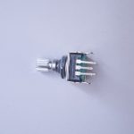
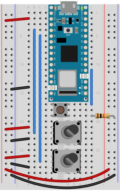
For this exercise, you’re going to need two analog inputs to your microcontroller, and one digital input. It doesn’t matter what they are, so use something that’s easy for you to set up. The photos and schematic in this lab show potentiometers and a pushbutton. You don’t have to use these, though. Any three sensor inputs will do the job. If you’re looking for options, consider:
As long as you have three sensors that will output changing readings, you can follow this lab.
Connect the two analog sensors to analog pins 0 and 1 like you did in the analog input to Arduino lab. Connect a pushbutton to digital pin 2 like you did in the digital input and output with Arduino lab.
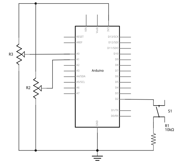
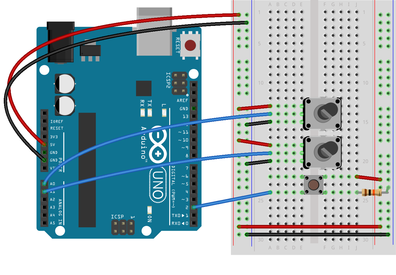
(Diagrams made with Fritzing, a circuit design program)
You’re going to program the microcontroller to read the pushbutton and two analog sensors just like you did in the Intro to Serial Communications Lab. When you have to send multiple data items, you need a way to separate them. If you’re sending them as ASCII-encoded strings, it’s simple: you can just put non-numeric punctuation bytes between them (like a comma or a space) and a unique termination punctuation at the end (like a newline and/or carriage return).
This program will send the two analog sensor values and then the pushbutton. All three will be ASCII-encoded numeric strings, separated by commas. The whole line of sensor values will be terminated by carriage return (\r, ASCII 13) and newline (\n, ASCII 10).
const int buttonPin = 2;      // digital input

void setup() {
  // configure the serial connection:
  Serial.begin(9600);
  // configure the digital input:
  pinMode(buttonPin, INPUT);
}

void loop() {
  // read the first analog sensor:
  int sensorValue = analogRead(A0);
  // print the results:
  Serial.print(sensorValue);
  Serial.print(",");

  // read the second analog sensor:
  sensorValue = analogRead(A1);
  // print the results:
  Serial.print(sensorValue);
  Serial.print(",");

  // read the button:
  sensorValue = digitalRead(buttonPin);
  // print the results:
  Serial.println(sensorValue);
}
When you run this and output it to the Serial Monitor, you should see something like this:
348,363,1
344,362,1
345,363,1
344,375,0
365,374,0
358,369,0
355,369,0
352,373,0
356,373,0
Turn the potentiometers (or tweak the analog sensors) and push the button. Now you’ve got a data format: three sensors, comma-separated, terminated by carriage return and newline. This means that you already have an algorithm for how you’re going to program P5.js to read the serial input:
Now write a P5.js sketch that reads the data as formatted by the Arduino program above. Download the latest version of the P5.serialcontrol application if you haven’t already and save it in your Applications folder. When you run it, it will check serial ports on your machine. You don’t need to do anything with the app, just have it open.
You’ll need to know the name of your serial port to get started. If you’re not sure how to get this, see the Serial Input to P5.js lab for how to get a list of ports.
The sketch you’re going to write will control the microcontroller’s LED from P5.js. Dragging the mouse up and down the canvas will dim or brighten the LED, and typing 0 through 9 will set the LED’s brightness in increments from off (0) through almost full brightness (9). There’s an alternate sketch that will make changing tones if you prefer that instead of a changing LED. The sketch will also receive serial input from the microcontroller just as in the Serial Input to P5.js lab, so that you can see that the microcontroller is getting the same values you’re sending.
As you saw in the Serial Input to P5.js lab, you’ll need to copy the p5.seriaport.js lbrary into your sketch’s libraries folder. You’ll need to run p5.serialcontrol, or run the p5.serialserver from the command line as you did in the Serial Input to P5.js lab as well.
Make a P5.js sketch. If you’re using the p5.js web editor, make a new sketch. Click the Sketch Files tab, and then choose the index.html file. In the head of the document, look for this line:
<script src="https://cdnjs.cloudflare.com/ajax/libs/p5.js/1.4.0/p5.js"></script>
Right after that line, add this line:
<script language="javascript" type="text/javascript" src="https://cdn.jsdelivr.net/npm/p5.serialserver@0.0.28/lib/p5.serialport.js"></script>
The setup of your sketch will initialize the P5.serialport library and define your callback functions for serial events. , as you did in other sketches
Then in the setup(), create a canvas, make an instance of the serialport library, and declare your callback functions.
var serial;          // variable to hold an instance of the serialport library

function setup() {
  createCanvas(800, 600);          // make canvas
  smooth();                        // antialias drawing lines
  serial = new p5.SerialPort();    // make a new instance of the serialport library
  serial.on('list', printList);    // set a callback function for the serialport list event
  serial.on('connected', serverConnected); // callback for connecting to the server
  serial.on('open', portOpen);     // callback for the port opening
  serial.on('data', serialEvent);  // callback for when new data arrives
  serial.on('error', serialError); // callback for errors
  serial.on('close', portClose);   // callback for the port closing

  serial.list();                   // list the serial ports
}
This time, you’ll add a serialport select menu as you did in the Serial Input to P5.js lab.First, declare a global variable to hold the port menu at the top of your sketch like so:
var portSelector; // a select menu for the port list
Then change the printList function like so:
// get the list of ports:
function printList(portList) {
  // make a select menu and position it:
  portSelector = createSelect();
  portSelector.position(10,10);

  // portList is an array of serial port names
  for (var i = 0; i < portList.length; i++) {
    // Display the list the console:
    // console.log(i + " " + portList[i]);
    // add item to the select menu:
    portSelector.option(portList[i]);
  }
  // set a handler for when a port is selected from the menu:
  portSelector.changed(mySelectEvent);
}
When the select menu’s value has changed, you can assume a serial port has been selected, so write a handler to open it like so:
function mySelectEvent() {
  let item = portSelector.value();
   // if there's a port open, close it:
  if (serial.serialport != null) {
    serial.close();
  }
  // open the new port:
  serial.open(item);
}
From now on, when you run this sketch, you’ll need to select the serial port to open the port.
The rest of the serial event handlers are all the same as you saw in the P5.js Serial Input Lab, except for the serialEvent(). Here are all but the serialEvent():
function serverConnected() {
  console.log('connected to server.');
}

function portOpen() {
  console.log('the serial port opened.')
}

function serialError(err) {
  console.log('Something went wrong with the serial port. ' + err);
}

function portClose() {
 console.log('The serial port closed.');
}
Program the serialEvent() function to read the incoming serial data as a string until it encounters a carriage return and newline (‘\r\n’). Then check to see that the resulting string has a length greater than 0 bytes. If it does, use the split() function to split it in to an array of strings. If the resulting array is at least three elements long, you have your three sensor readings. The first reading is the first analog sensor, and can be mapped to the horizontal movement using the locH variable. The second is the second analog sensor and can be mapped to the locV variable. The third is the button. When it’s 0, set the circleColor variable equal to 255 and when it’s 1, set the variable to 0. Here’s how:
function serialEvent() {
  // read a string from the serial port
  // until you get carriage return and newline:
  var inString = serial.readStringUntil('\r\n');

  //check to see that there's actually a string there:
  if (inString.length > 0 ) {
    var sensors = split(inString, ',');            // split the string on the commas
    if (sensors.length > 2) {                      // if there are three elements
      locH = map(sensors[0], 0, 1023, 0, width);   // element 0 is the locH
      locV = map(sensors[1], 0, 1023, 0, height); // element 1 is the locV
      circleColor = 255 - (sensors[2] * 255);      // element 2 is the button
    }
  }
}
Note the mappings of sensor[0] and sensor[1]. You should use the input mappings for your accelerometer instead of 0 and 1023. If your analog values are greater than the width of the sketch or the height, the circle will be offscreen, which is why you have to map your sensor range to the screen size.
Program the draw() function to draw a circle that’s dependent on three global variables, locH, locV, and circleColor. Add these three globals to the top of the program:
var locH = 0;
var locV = 0;        // location of the circle
var circleColor = 255; // color of the circle
Finally, here is the draw function:
function draw() {
  background(0);               // black background
  fill(circleColor);           // fill depends on the button
  ellipse(locH, locV, 50, 50); // draw the circle
}
If you run this, you should see the circle moving onscreen whenever you tilt the accelerometer. When you press the pushbutton, the circle will disappear. Okay, it’s not exactly a mouse, but you are controlling an animation from a device that you built.
You’ve seen now that by coming up with a serial format (called a protocol), you can write the algorithm for receiving it even before you see any data. You can send multiple pieces of data this way, as long as you format it consistently.
Sometimes you can run into a problem when the sender sends faster than the receiver can read. When this happens, the receiver program slows down as the serial buffer fills up. You can manage this by implementing some form of flow control. The simplest way do to this is using a call-and-response method, where the sending program only sends when it’s told to do so, and the receiving program has to request new data every time it finishes reading what it’s got.
You can add handshaking to the code above fairly simply. Modify the Arduino code as follows. First, add a a new block of code in the setup() This block sends out a message until it gets a byte of data from the remote computer:
void setup() {
  Serial.begin(9600);
  while (Serial.available() <= 0) {
    Serial.println("hello"); // send a starting message
    delay(300);              // wait 1/3 second
  }
}
Now, modify the loop() by adding an if() statement to look for incoming serial data and read it.
void loop() {
  if (Serial.available() > 0) {
    // read the incoming byte:
    int inByte = Serial.read();
    // read the sensor:
    sensorValue = analogRead(A0);
    // print the results:
    Serial.print(sensorValue);
    Serial.print(",");

    // read the sensor:
    sensorValue = analogRead(A1);
    // print the results:
    Serial.print(sensorValue);
    Serial.print(",");

    // read the sensor:
    sensorValue = digitalRead(buttonPin);
    // print the results:
    Serial.println(sensorValue);
  }
}
The rest of the sketch remains the same. When you run this and open the serial monitor, you’ll see:
hello
hello
hello
hello
Type any character in the output box and click Send. You’ll get a string of sensor values at the end of your hellos:
510,497,0
Type another character and click Send. It doesn’t matter what character you send, but the loop will always wait for an incoming byte before sending a new set of sensor values. When you write a program to receive this format, it just has to behave the same way you did:
Next, modify the P5.js sketch. Most of the changes are in the serialEvent() function. The initial “hello” messages will trigger this function, so when you get a “hello” or any other string, you need to send a byte back so that the Arduino has a byte available to read. Here’s the new serialEvent():
function serialEvent() {
  // read a string from the serial port
  // until you get carriage return and newline:
  var inString = serial.readStringUntil('\r\n');
  //check to see that there's actually a string there:
  if (inString.length > 0) {
    if (inString !== 'hello') { // if you get hello, ignore it
      var sensors = split(inString, ','); // split the string on the commas
      if (sensors.length > 2) { // if there are three elements
        locH = map(sensors[0], 0, 1023, 0, width); // element 0 is the locH
        locV = map(sensors[1], 0, 1023, 0, height); // element 1 is the locV
        circleColor = 255 - (sensors[2] * 255); // element 2 is the button
      }
    }
    serial.write('x'); // send a byte requesting more serial data
  }
}
You also need to add a line to the openPort() function like so:
function portOpen() {
  console.log('the serial port opened.')
  // send a byte to prompt the microcontroller to send:
  serial.write('x');
}
The reason for this is that if your Arduino has already broken out of the loop (let’s say you opened the Serial monitor to check), then it is waiting for a byte from p5.js to send the next block of code. By sending a byte when you know the port has just been opened in p5.js, you force the Arduino to send you new data.
That’s it. Your sketch should still run just as it did before, though the serial communication is managed better now, because Arduino’s only sending when P5.js is ready to receive.
The full code for all the examples in this lab can be found in this gitHub repository.
All the examples shown here sent the sensor values as ASCII-encoded strings. As mentioned above, that means you sent three bytes to send a three-digit value. If that same value was less than 255, you could send it in one raw binary byte. So ASCII is definitely less efficient. However, it’s more readable for debugging purposes, and if the receiving program is well-suited to convert strings to numbers, then ASCII is a good way to go. If the receiver’s not so good at converting strings to numbers (for example, it’s more challenging to read a multiple byte string in Arduino than in Processing) then you may want to send your data as binary values.
The punctuation method for sending multiple serial values may seem simpler, but it has its limitations. You can’t easily use it to send binary values, because you need to have a byte with a unique value for the punctuation. In the example above, you’re using the value 10 (ASCII newline) as punctuation, so if you were sending your sensor values as raw bytes, you’d be in trouble when the sensor’s value is 10. The receiver would interpret the 10 as punctuation, not as a sensor value. In contrast, call-and-response can be used whether you’re sending data as raw binary values or as ASCII-encoded values.
Sometimes the receiver reads serial data slower than the sender sends it. For example, if you have a program that does a lot of graphic work, it may only read serial data every few milliseconds. The serial buffer will get full in that case, you’ll notice a lag in response time. This is when it’s good to switch to a call-and-response method.
You just duplicated the basic functionality of a mouse; that is, a device with two analog sensors that affect X and Y, and a digital sensor (mouse button). What applications can you think of that could use a better physical interface for a mouse? A video editor that scrubs forward and back when you tilt a wand? An action game that reacts to how hard you hit a punching bag? An instructional presentation that speeds up if you shift in your chair too much? A music program driven by a custom musical instrument that you design?
Create a prototype in Arduino and P5.js, Node.js, Processing, or whatever programming environment you choose. Come up with a physical interface that makes it clear what actions map to what movements and actions. Figure out which actions can and should be possible at the same time. Present a working software and hardware model of your idea.
n this lab, you’ll generate an analog output value from a potentiometer, then send that value via asynchronous serial communication to P5.js. You’ll use that value in P5.js to draw a graph.
In this lab, you’ll generate an analog output value from a potentiometer, then send that value via asynchronous serial communication to P5.js. You’ll use that value in P5.js to draw a graph.
Serial communication to a web page in a browser isn’t something you see every day. Web browsers don’t usually have access to a computer’s serial ports. In order to get your browser-based applications to communicate with a microcontroller serially, you need a program that can both serve HTML/JavaScript pages, and communicate with the serial port. When you’re making projects with P5.js, you can achieve this by using the P5.serialport library and the P5.serialcontrol app by Shawn Van Every (updated by Jiwon Shin). When you use the p5.serialport library, it communicates with the p5.serialcontrol app, a WebSocket server that gives you access to serial devices attached to your computer. This lab shows you how to do that.
To get the most out of this tutorial, you should know what a microcontroller is and how to program them. You should also understand asynchronous serial communication between microcontrollers and personal computers. You should also understand the basics of P5.js. This video on serial from Arduino to p5.js may be useful.
For this lab, you’ll need the hardware below, and you’ll need to create a p5.js sketch. You’ll also use the p5.seri alport library and the P5.serialcontrol app. You can use the p5.js web editor or your favorite text editor for this (the Visual Studio Code editor or the Atom text editor work well).
Figures 1-4 below show the parts you’ll need for this exercise. Click on any image for a larger view.

For this exercise you’re going to attach a potentiometer as an analog input to your microcontroller, and send the sensor’s reading serially to p5.js via the p5.serialcontrol app.
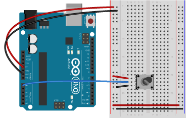
Connect power and ground on the breadboard to the microcontroller. On the Arduino module, use the 5V or 3.3V (depending on your model) and any of the ground connections. Figures 5 and 6 show connections for an Arduino Uno and a Nano, respectively.

The Uno’s 5V output hole is connected to the red column of holes on the far left side of the breadboard (Figure 5). The Uno’s ground hole is connected to the blue column on the left of the board. The red and blue columns on the left of the breadboard are connected to the red and blue columns on the right side of the breadboard with red and black wires, respectively. These columns on the side of a breadboard are commonly called the buses. The red line is the voltage bus, and the black or blue line is the ground bus.
Images made with Fritzing, a circuit drawing application
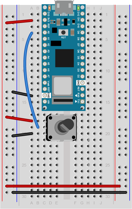
The Nano is mounted at the top of the breadboard (Figure 6), straddling the center divide, with its USB connector facing up. The top pins of the Nano are in row 1 of the breadboard.
The Nano, like all Dual-Inline Package (DIP) modules, has its physical pins numbered in a U shape, from top left to bottom left, to bottom right to top right. The Nano’s 3.3V pin (physical pin 2) is connected to the left side red column of the breadboard. The Nano’s GND pin (physical pin 14) is connected to the left side black column. These columns on the side of a breadboard are commonly called the buses. The red line is the voltage bus, and the black or blue line is the ground bus. The blue columns (ground buses) are connected together at the bottom of the breadboard with a black wire. The red columns (voltage buses) are connected together at the bottom of the breadboard with a red wire.
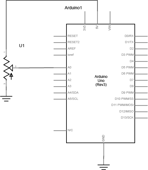
Connect a potentiometer to analog in pin 0 of the module. Figure 7 shows the schematic and figures 8 and 9 show the potentiometer connected to an Arduino and Nano, respectively.
Program your Arduino to read the analog input as follows:
void setup() {
  Serial.begin(9600); // initialize serial communications
}

void loop() {
  // read the input pin:
  int potentiometer = analogRead(A0);
  // remap the pot value to fit in 1 byte:
  int mappedPot = map(potentiometer, 0, 1023, 0, 255);
  // print it out the serial port:
  Serial.write(mappedPot);
  // slight delay to stabilize the ADC:
  delay(1);
}
To communicate with your microcontroller serially, you’re going to use the P5.js serialport library and the p5.serialcontrol app. The P5.js serialport library can’t access your serial ports directly when a sketch is running in a browser because the browser doesn’t have direct access to the serial port. But it can communicate with another program on your computer that can exchange data with the serialport. p5.serialcontrol is the app that connects your sketch, running in a browser, with the serial ports on your computer as shown in Figure 10.
Once you gain an understanding of serial communication, you can use any program that can connect with your computer’s serial ports to communicate with a microcontroller. Processing, Max/MSP, and OpenFrameworks are three other popular multimedia programming environments that can communicate via the serial ports. You can also do this with Unity, Unreal, or any other programming environment that can access the serial ports.
Download the latest version of the P5.serialcontrol application and save it in your Applications folder. When you run it, it will check serial ports on your machine. You don’t need to do anything with the app, just have it open. However, remember this most important fact:
That means that when you want to reprogram your Arduino from the Arduino IDE, you need to quit p5.serialcontrol to do so. Then, reopen p5.serialcontrol when you’re done reprogramming the Arduino. You don’t need to quit the Arduino IDE each time, because it knows to release the serial port when it’s not programming. However, you do need to close the Serial Monitor in the Arduino IDE when you are using p5.serialcontrol.
Now you’re ready to make a P5.js sketch. If you’re using the p5.js web editor, make a new sketch. Click the Sketch Files tab, and then choose the index.html file. In the head of the document, look for this line:
<script src="https://cdnjs.cloudflare.com/ajax/libs/p5.js/1.4.0/p5.js"></script>
Right after that line, add this line:
<script language="javascript" type="text/javascript" src="https://cdn.jsdelivr.net/npm/p5.serialserver@0.0.28/lib/p5.serialport.js"></script>
To start off, your programming environment needs to know what serial ports are available in the operating system. Open the sketch.js file and change it to the following:
let serial; // variable to hold an instance of the serialport library

function setup() {
  serial = new p5.SerialPort(); // make a new instance of the serialport library
  serial.on('list', printList); // set a callback function for the serialport list event

  serial.list(); // list the serial ports
}

// get the list of ports:
function printList(portList) {
  // portList is an array of serial port names
  for (var i = 0; i < portList.length; i++) {
    // Display the list the console:
    console.log(i + portList[i]);
  }
}
When you run this p5.js sketch in a browser, you’ll get a list of the available serial ports in the console. This list will look just like the list of serial ports you see in the Arduino Tools menu. Find the name of your port in the list. Later, you’ll assign that name to a global variable called portName.
Now you’re ready to listen for some incoming serial data.
JavaScript, the language on which p5.js is based, relies heavily on events and callback functions. An event is generated by the operating system when something significant happens, like a serial port opening, or new data arriving in the port. In your sketch, you write a callback function to respond to that event. The serialport library uses events and callback functions as well. It can listen for the following serialport events:
You’re already using a callback for the ‘list’ event in the code above. You set a callback for the ‘list’ event, then you called it with serial.list(). Generally, you should set your callbacks before you use them like this.
To use the rest of the serialport library’s events, you need to set callback functions for them as well. Add a new global variable called portName and initialize it with the name of your serial port that you got from the listPorts() function before. Then change your setup() function to include callbacks for open, close, and error like so:
let serial;          // variable to hold an instance of the serialport library
let portName = '/dev/cu.usbmodem1421';  // fill in your serial port name here

function setup() {
  serial = new p5.SerialPort();       // make a new instance of the serialport library
  serial.on('list', printList);  // set a callback function for the serialport list event
  serial.on('connected', serverConnected); // callback for connecting to the server
  serial.on('open', portOpen);        // callback for the port opening
  serial.on('data', serialEvent);     // callback for when new data arrives
  serial.on('error', serialError);    // callback for errors
  serial.on('close', portClose);      // callback for the port closing

  serial.list();                      // list the serial ports
  serial.open(portName);              // open a serial port
}
Notice the final line of the setup(). It’s going to generate an ‘open’ event, which will be handled by a function called portOpen().
In asynchronous serial communications, both computers have to set the same data rate in order to communicate. In Arduino, you set the data rate with Serial.begin(9600); In p5.js, 9600 bits per second is the default, so you don’t have to set the rate if you want 9600bps. But if you want to set the rate to another value, do it like this:
let options = { baudrate: 9600}; // change the data rate to whatever you wish
serial.open(portName, options);
Now add new functions to respond to the callbacks you just declared. These come after your setup() function:
function serverConnected() {
  console.log('connected to server.');
}

function portOpen() {
  console.log('the serial port opened.')
}

function serialEvent() {

}

function serialError(err) {
  console.log('Something went wrong with the serial port. ' + err);
}

function portClose() {
  console.log('The serial port closed.');
}
The function that matters the most, though, is serialEvent(), the one that responds to new data. Each time a new byte arrives in the serial port, this function is called. Now it’s time to make serialEvent() do some work. Add a new global variable at the top of your sketch called inData like so:
let serial;          // variable to hold an instance of the serialport library
let portName = '/dev/cu.usbmodem1421';  // fill in your serial port name here
let inData;                             // for incoming serial data
Then modify the serialEvent() function like so:
function serialEvent() {
  inData = Number(serial.read());
}
Next, make the draw() function to print the sensor value to the screen. Start by adding a createCanvas() call to the top of your setup() like so:
function setup() {
createCanvas(400, 300);
Then here’s your draw() function:
function draw() {
   background(0);
   fill(255);
   text("sensor value: " + inData, 30, 50);
}
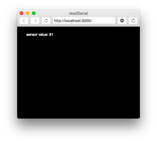
When you run your sketch now, you should get something like the sketch shown in Figure 13.
The sensor value onscreen should change as you turn your potentiometer. Congratulations! You’ve got P5.js talking to your microcontroller.
Every time your microcontroller sends a byte serially using Serial.write(), the computer receives it and generates a ‘data’ event. Then your serialEvent() function is called. It reads the byte as a number, and stores it in the global variable inData. The draw() method just uses the latest value of inData in the text string it displays on the screen.
You may be wondering why you’re mapping the sensor value or dividing it by 4 in the Arduino sketch above. That’s because in order to send the sensor value as a single byte, it must be between 0 and 255, or no more than 28 bits.
In testing this, you may have put a console.log() statement in the serialEvent() function in your P5.js sketch. When you did, you would have noticed that it causes a lag in the sketch, and the console.log() statements continue even after you stop the sketch. This is because the operating system keeps the incoming serial data in a buffer, and P5.js isn’t reading and printing it as fast as Arduino is sending it.
You might think, “Okay, then I’ll just put a delay() in my Arduino sketch to slow it down.” That’s a bad idea. When you put in a delay, it means you’re only reading your sensor when that delay is not running. You can miss critical sensor events while that delay is in progress. Even a relatively small delay, for example 30ms, can make it difficult to reliably read state changes in a switch or peaks in an analog sensor. Don’t use delays if you can avoid it. For more on how to handle the flow of serial data from Arduino to P5.js and back, see the Duplex Serial Flow in P5.js lab.
If you don’t want to have to remember the serial port name every time you run the sketch, you can add a drop-down menu to select the port. Add a global variable at the top of your sketch called portSelector like so:
// HTML Select option object:
let portSelector;
Then replace the printList() function with the following:
// make a serial port selector object:
function printList(portList) {
  // create a select object:
  portSelector = createSelect();
  portSelector.position(10, 10);
  // portList is an array of serial port names
  for (var i = 0; i < portList.length; i++) {
    // add this port name to the select object:
    portSelector.option(portList[i]);
  }
  // set an event listener for when the port is changed:
  portSelector.changed(mySelectEvent);
}
Then add an extra function that will get called when the port list is changed. This function will get the name of the port you select, close any port that’s open, and open the port you asked for:
function mySelectEvent() {
  let item = portSelector.value();
   // if there's a port open, close it:
  if (serial.serialport != null) {
    serial.close();
  }
  // open the new port:
  serial.open(item);
}
If you choose this approach, you can delete the global portName variable at the top of your sketch, and the line in your setup() that says:
serial.open(portName); // open a serial port
Instead of opening the serial port once at the beginning of your code, you’re now opening and closing the port every time you select from this menu.
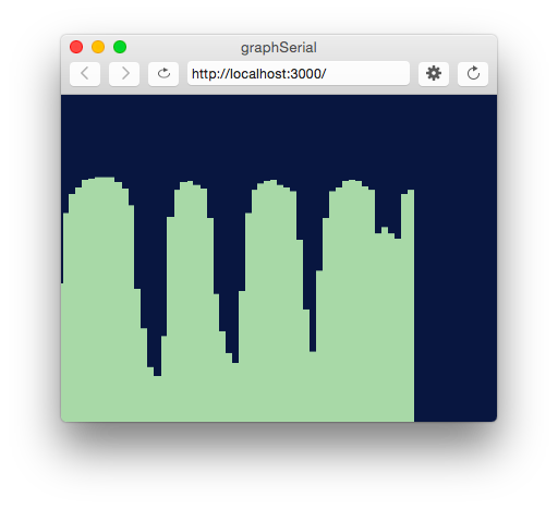
It would be useful to see a graph of the sensor values over time. You can do that by modifying the draw() method to draw the graph. To do this, add a new global variable at the top of your sketch called xPos. You’ll use this to keep track of the x position of the latest graph line:
let xPos = 0; // x position of the graph
Because of the way the graphing function below works, you can’t reset the background every time through the draw() loop. So take the background() command and put it in the setup() function instead of the draw(), as shown below. That way it runs once, then not again. As long as you’re at it, switch from black & white to a nice blue color:
function setup() {
  createCanvas(400, 300);
  background(0x08, 0x16, 0x40);
Now make a new function called graphData(). It’ll take a number value as a parameter, and it will draw a line on the screen that’s mapped to the number value. Then it will increment xPos so that the next line is drawn further along. It will also check if the xPos is at the right edge of the screen, and reset the screen by calling background() again if it is:
function graphData(newData) {
  // map the range of the input to the window height:
  var yPos = map(newData, 0, 255, 0, height);
  // draw the line in a pretty color:
  stroke(0xA8, 0xD9, 0xA7);
  line(xPos, height, xPos, height - yPos);
  // at the edge of the screen, go back to the beginning:
  if (xPos >= width) {
    xPos = 0;
    // clear the screen by resetting the background:
    background(0x08, 0x16, 0x40);
  } else {
    // increment the horizontal position for the next reading:
    xPos++;
  }
}
Finally, take everything out of the draw() function and just call graphData() from there:
function draw() {
  graphData(inData);
}
When you run the sketch now, you should get a graph, as shown in Figure 14.
If you’d like to see a fancier graphing sketch, check out this sketch, which adds chart.js to make a better graph. Chart.js is a great tool for graphing data in JavaScript, and it integrates well with p5.js.
This works well if you want to read your sensor values as a single byte, but what if you want a larger range of numbers? What if you want the full 0 to 1023 that analogRead() can output instead of just 0 to 255? To do this, you need to send the data as an ASCII-encoded numeric string from the microcontroller, and you need to read and interpret the incoming data in P5 as an ASCII-encoded numeric string as well.
Change your Arduino program to the following:
void setup() {
 Serial.begin(9600); // initialize serial communications
}

void loop() {
 int potentiometer = analogRead(A0);                  // read the input pin
 int mappedPot = map(potentiometer, 0, 1023, 0, 255); // remap the pot value to fit in 1 byte
 Serial.println(mappedPot);                           // print it out the serial port
 delay(1);                                            // slight delay to stabilize the ADC
}
Now it will print the potentiometer’s value as an ASCII-encoded numeric string, and it will add a carriage return byte and a newline byte at the end, because that’s what println() does.
Once you’ve uploaded this to your Arduino, run your P5 sketch again. Try adding println(inData); at the end of your serialEvent() function. When your P5 sketch reads the data from this Arduino program, you get very low values, and every so often you see the value 10 followed by the value 13. What’s going on?
When a computer ASCII-encodes a number, it converts that number to a string of bytes, each of which is the ASCII value for a numeral in the number. For example, the number 865 gets converted to three bytes, as shown in Figure 15.

If there’s a carriage return byte and a newline byte after this, the string is five bytes, and the last two bytes’ values are 13 (carriage return, or \r in most programming languages) and 10 (newline or \n in most programming languages), respectively.
Your P5.js sketch is reading every byte’s value and graphing it. That’s why you get a graph of very low values, with a bunch of them being 13 and 10. The Arduino is ASCII-encoding the potentiometer values, but the P5 sketch is interpreting the bytes as if they’re not encoded that way.
Now change the serialEvent() function like so:
function serialEvent() {
  // read a byte from the serial port, convert it to a number:
  inData = serial.readLine();
}
Run it again. What’s changed? Now you’re getting a graph kind of like you were before. The serial.readLine(); command reads the incoming serial data as a string, and when that string happens to be all-numeric, it converts it to a number. So you’re getting the ASCII-encoded string as a number again. But now there are gaps. Why?
Remember, the ‘data’ event occurs every time a new byte comes in the serial port. Now that you’re sending an ASCII-encoded string, every potentiometer reading is several bytes long. So you only get a complete string every three to six bytes (three for “0\r\n” and six for “1023\r\n”). Sometimes, when the serialEvent() function calls serial.readLine(); it gets nothing. That’s when draw() draws the gaps. You need to change your function to check that the resulting string is actually a valid number before you put the string into inData. First, create a local variable to get the string, then check to see if the string’s length is greater than zero. If it is, then put it into inData so that the other functions in the sketch can use the new data. Here’s how you do that:
function serialEvent() {
  // read a string from the serial port:
  var inString = serial.readLine();
  // check to see that there's actually a string there:
  if (inString.length > 0 ) {
  // convert it to a number:
  inData = Number(inString);
  }
}
Here is a link to the complete serial in p5.js sketch.
Now you’re able to send in a number of any value to P5.js. You don’t have to limit your input to a 0-255 value range. See if you can modify the Arduino sketch and the P5.js sketch to exchange a potentiometer value that spans the whole range from 0 to 1023.
note: readLine() is the same as readStringUntil(‘\r\n’);
The full code for all the examples in this lab can be found in this gitHub repository.
You know that p5.js can run in any browser, but what happens to a sketch using p5.serialport.js when it’s running on someone else’s computer, or on your phone or tablet? What serial port does it connect to? That depends on what you do when you initialize it.
When you call new p5.SerialPort() with no parameter between the parentheses, the library attempts to connect to p5.serialcontrol app on the computer that’s running the sketch. If you’re running the sketch on your laptop’s browser, then the library connects to the your laptop’s ports through p5.serialcontrol. But imagine you run the sketch on your phone, but you want the sketch to connect to an Arduino connected to a serial port on your laptop. To do this, the your laptop has to be the web host for your sketch, as well as the computer running p5.serialcontrol. In addition, your laptop and the device running the sketch have to be on the same local network.
note: this will not work if your sketch is in the p5.js web editor. You’ll need to download the sketch and edit it on your laptop to make it work.
Launch the p5.serialcontrol app. It will display the IP address of the computer on which it’s running. Copy it, and modify the new p5.SerialPort() line at the beginning of your setup() function, adding the IP address like so:
serial = new p5.SerialPort('10.17.34.128'); // fill in your own IP address in place of the one shown here
Save the sketch, then open a command line interface on your computer (the Terminal app in MacOS, for example). Change directories to the directory where your sketch lives (for example, cd ~/Documents/p5_sketches/mySerialSketch) and run a simple web server like so:
$ python -m SimpleHTTPServer 8080
Now open a browser, either on your computer or your phone or tablet, and enter the following address:
To close this server, type control-C. You can modify the sketch as much as you want, and reload it in the browser without having to re-start the server.
The sketch should run, and operate just as you saw earlier. This approach is handy if you want to use a tablet or phone as a multimedia device to control sounds or videos, controlled by physical sensors on a microcontroller.
Note: the IP address of your computer will change as you move from one network to another (for example, from school to home). If you want to get the IP address dynamically, you can use this: window.location.hostname. This will always return the address of the host computer that served the webpage. So, for example, changing the line above to read as follows will automatically adjust the hostname each time.
// use the hostname of the computer that served this page:
serial = new p5.SerialPort(window.location.hostname);
For more detail on this, see the video Screens: Communicating from a mobile device to a microcontroller using p5.js serialControl.
In this lab, you saw how to connect an Arduino microcontroller to a P5.js sketch using a webSocket-to-serial server, P5.serialserver, and the P5.serialport library. You sent data from Arduino to the sketch as a raw binary value — that is, a single byte ranging from 0 to 255 — and you sent it as an ASCII-encoded numeric string with a carriage return and newline at the end. See Table 1 below to review what are suitable data formats for different types/sizes of data and which functions to use on p5.js and Arduino for serial communication.
| Data to Send | within 0-255 (< 2^8 = 1 byte) | Multiple values |
|---|---|---|
| Send as: | ||
| Arduino -> | ||
| -> p5.js | =readStringUntil('\r\n') |
Notes about sending Ascii data:
Understanding the difference between ASCII-encoded strings and raw binary data is central to all serial communications. For more examples of this in action, see the Serial Output from P5.js lab.
In this lab you’ll learn some methods for determining when a sensor’s reading changes significantly.
Microcontrollers can sense what’s going on in the physical world using digital and analog sensors, but a single sensor reading doesn’t tell you much. In order to tell when something significant happens, you need to know when that reading changes. For example, when a digital input changes from LOW to HIGH or the reverse, you can tell that a person closed or opened a switch. When a force-sensing resistor reaches a peak reading, you know that something has hit the sensor. In this lab, you’ll learn how to program your microcontroller to look for three common changes in sensor readings that give you information about events in the physical world: state change detection on digital sensors, and threshold crossing and peak detection on analog sensors. You’ll use these three techniques all the time when you’re designing to read users’ actions.
To get the most out of this lab, you should be familiar with the following concepts. You can check how to do so in the links below:


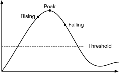
Before you start trying to detect specific sensor change events, you should know what your sensor’s changes look like over time. You might want to start by viewing the change on an oscilloscope, or by using the Serial Plotter in the Arduino IDE Tools menu (command-shift-L), or a graphing program like the one shown in the WebSerial input to p5.js Lab or Serial Output From Arduino to Processing lab to understand how your sensors change. Figure 7 shows a typical sensor change graph.
Sensor changes are described in terms of the change in the sensor’s property, often a voltage output, over time. The most important cases to consider for sensor change are the rising and falling edges of a digital or binary sensor, and the rising and falling edges and the peak of an analog sensor. The graphs in Figures 8 and 9 of sensor voltage over time illustrate these conditions:

Connect power and ground on the breadboard to power and ground from the microcontroller. On the Arduino module, use the 5V or 3.3V (depending on your model) and any of the ground connections, as shown in Figures 10 and 11.
Figure 10 shows an Arduino Uno on the left connected to a solderless breadboard, right. The Uno’s 5V output hole is connected to the red column of holes on the far left side of the breadboard. The Uno’s ground hole is connected to the blue column on the left of the board. The red and blue columns on the left of the breadboard are connected to the red and blue columns on the right side of the breadboard with red and black wires, respectively. These columns on the side of a breadboard are commonly called the buses. The red line is the voltage bus, and the black or blue line is the ground bus.
Figure 11 shows an Arduino Nano mounted on a solderless breadboard. The Nano is mounted at the top of the breadboard, straddling the center divide, with its USB connector facing up. The top pins of the Nano are in row 1 of the breadboard.
The Nano, like all Dual-Inline Package (DIP) modules, has its physical pins numbered in a U shape, from top left to bottom left, to bottom right to top right. The Nano’s 3.3V pin (physical pin 2) is connected to the left side red column of the breadboard. The Nano’s GND pin (physical pin 14) is connected to the left side black column. These columns on the side of a breadboard are commonly called the buses. The red line is the voltage bus, and the black or blue line is the ground bus. The blue columns (ground buses) are connected together at the bottom of the breadboard with a black wire. The red columns (voltage buses) are connected together at the bottom of the breadboard with a red wire.
Images made with Fritzing
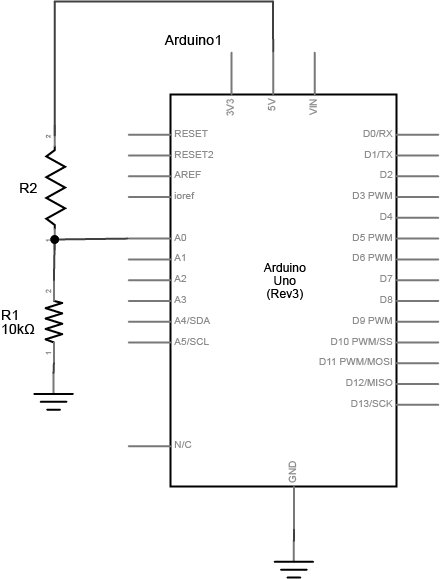
Connect a pushbutton to digital input 2 on the Arduino. Figures 12 and 13 show the schematic and breadboard views of this for an Arduino Uno, and Figure 14 shows the breadboard view for an Arduino 33 IoT.
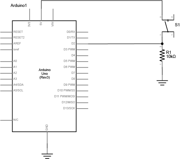
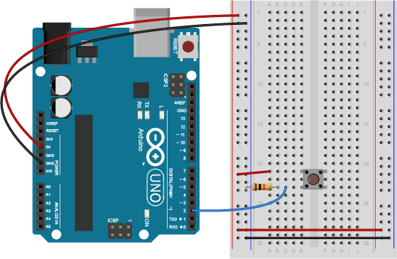
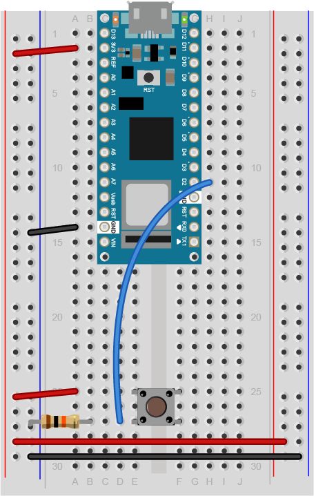
The +3.3 volts and ground pins of the Arduino are connected by red and black wires, respectively, to the left side rows of the breadboard. +3.3 volts is connected to the left outer side row (the voltage bus) and ground is connected to the left inner side row (the ground bus). The side rows on the left are connected to the side rows on the right using red and black wires, respectively, creating a voltage bus and a ground bus on both sides of the board. The pushbutton is mounted across the middle divide of the solderless breadboard. A 10-kilohm resistor connects from the same row as pushbutton’s bottom left pin to the ground bus on the breadboard. There is a wire connecting to digital pin 2 from the same row that connects the resistor and the pushbutton. The top left pin of the pushbutton is connected to +3.3V.
In the Digital Lab you learned how to read a pushbutton using the digitalRead() command. To tell when a pushbutton is pushed, you need to determine when the button’s state changes from off to on. With the button wired as you have it here, the button’s state will change from 0 to 1. In order to know that, you need to know not only what the current state of the button is, but you also need to remember the state of the button the previous time you read it. This is called state change detection. To do this, set up a global variable to store the button’s previous state. Initialize the button in your program’s setup() function using the pinMode() command. Then, in the loop() function, write a block of code that reads the button and compares its state to the previous state variable. To do this, you need to read the button, check the current button state against the last state, then save the current state of the button in a variable for the next time through the loop like so:
int lastButtonState = LOW;    // state of the button last time you checked

void setup() {
  // make pin 2 an input:
  pinMode(2, INPUT);
}

void loop() {
  // read the pushbutton:
  int buttonState = digitalRead(2);

  // check if the current button state is different than the last state:
  if (buttonState != lastButtonState) {
     // do stuff if it is different here
  }

  // save button state for next comparison:
  lastButtonState = buttonState;
}
If buttonState is not equal to lastButtonState, then the button has changed. Then you want to check if the current state is HIGH. If it is, then you know the button has changed from LOW to HIGH. That means your user pressed it. Print out a message to that effect.
int lastButtonState = LOW;   // state of the button last time you checked

void setup() {
  // initialize serial communication:
  Serial.begin(9600);
  // make pin 2 an input:
  pinMode(2, INPUT);
}

void loop() {
  // read the pushbutton:
  int buttonState = digitalRead(2);

  // if it's changed and it's high, toggle the mouse state:
  if (buttonState != lastButtonState) {
    if (buttonState == HIGH) {
      Serial.println("Button was just pressed.");
    }
  }
  // save button state for next comparison:
  lastButtonState = buttonState;
}
Your code should only print out a message when the button changes state. For every button press, you should get one line of code. You can use this technique any time you need to tell when a digital input changes state.
One of the many things you can do with state change detection is to count the number of button presses. Each time the button changes from off to on, you know it’s been pressed once. By adding another global variable and incrementing it when you detect the button press, you can count the number of button presses. Add a global variable at the top of your program like so:
int lastButtonState = LOW;   // state of the button last time you checked
int buttonPresses = 0;       // count of button presses
Then in the if statement that detects the button press, add one to the button press:
 if (buttonState == HIGH) {
      buttonPresses++;
      Serial.print("Button has been pressed ");
      Serial.print(buttonPresses);
      Serial.println(" times.");
    }
The key to detecting state change is the use of a variable to save the current state for comparison the next time through the loop. This is a pattern you’ll see below as well:
int lastSensorState = LOW;   // sensor's previous state
// other globals and the setup go here

void loop() {
  // read the sensor:
  int sensorState = digitalRead(2);

  // if it's changed:
  if (sensorState != lastSensorState) {
    // take action or run a more detailed check
  }
  // save sensor state for next comparison:
  lastSensorState = sensorState;
}
Sometimes you want to take a different action on a short button press than you do on a long button press. To do this, you need to know now only when the button changes, but also how long it stays in a pressed state after it changes. Here’s how you might do that.
Start with some global variables for the button pin number, and the length of a long press or a short press, in milliseconds. You also need a variable to track how long the button has been pressed, and as in the code above, you need a variable to track the last button state. Add another variable called pressTime, which will keep track of the last time the button went from LOW to HIGH:
// the input pin:
int buttonPin = 2;

// the length of the presses in ms:
int longPress = 750;
int shortPress = 250;
// variable for how long the user actually presses:
long pressTime = 0;

// previous state of the button:
int lastButtonState = LOW;
In the setup(), set the button pin mode and initialize serial as you did before:
void setup() {
  // initialize serial and I/O pin:
  Serial.begin(9600);
  pinMode(buttonPin, INPUT);
}
In the loop, look for the button to change state, and when it does, note the press time in the pressTime variable. When the button is released (goes from HIGH to LOW), calculate how ling it was pressed, and print it:
void loop() {
  // read the button:
  int buttonState = digitalRead(buttonPin);

  // if the button has changed:
  if (buttonState != lastButtonState) {
    // if the button is pressed, start a timer:
    if (buttonState == HIGH) {
      pressTime = millis();
    }
    // if it's released, stop the timer:
    if (buttonState == LOW) {
      long holdTime = millis() - pressTime;
      // take action for long press, short press, or tap:
      if (holdTime > longPress) {
        Serial.println("long press");
      } else if (holdTime > shortPress) {
        Serial.println("short press");
      } else {
        Serial.println("Tap");
      }
    }
  }
  // save button state for next time:
  lastButtonState = buttonState;
}
You can see from this that you’ve actually got three states now, long press (> 750ms), short press (250-750ms), and tap (>250ms). With this, you can make one button do three things.
When you’re using analog sensors, binary state change detection like you saw above is not usually effective, because your sensors can have multiple states. Remember, an analog sensor on an Arduino can have up to 1024 possible states. The simplest form of analog state change detection is to look for the sensor to rise above a given threshold in order to take action. However, if you want the action be triggered only once when your sensor passes the threshold, you need to keep track of both its current state and previous state.
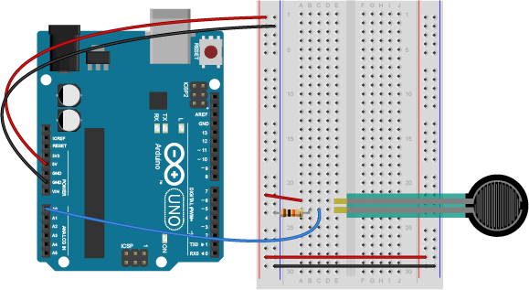
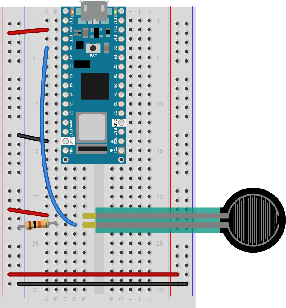
To build this example, you’ll need an analog sensor attached to your microcontroller, as shown in the Analog Input lab. Figures 15-17 show how to connect it.
This example is very similar to the one above:
int lastSensorState = LOW;   // sensor's previous state
int threshold = 512;   // an arbitrary threshold value

void setup() {
  Serial.begin(9600);
}

void loop() {
  // read the sensor:
  int sensorState = analogRead(A0);

  // if it's above the threshold:
  if (sensorState >= threshold) {
    // check that the previous value was below the threshold:
     if (lastSensorState < threshold) {
        // the sensor just crossed the threshold
        Serial.println("Sensor crossed the threshold");
     }
  }
  // save button state for next comparison:
  lastSensorState = sensorState;
}
This program will give you an alert only when the sensor value crosses the threshold when it’s rising. You won’t get any reading when it crosses the threshold when it’s falling, and you’ll only get one message when it crosses the threshold. It is possible to sense a threshold crossing when the sensor is falling, by reversing the greater than and less than signs in the example above. The threshold you set depends on your application. For example, if you’re using a light sensor to detect when it’s dark enough to turn on artificial lighting, you’d use the example above, and turn on the light when the threshold crossing happens. But you might also need to check for the falling threshold crossing to turn off the light.
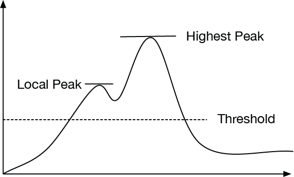
There are times when you need to know when an analog sensor reaches its highest value in a given time period. This is called a peak. To detect a peak, you first set an initial peak value at zero. Pick a threshold below which you don’t care about peak values. Any time the sensor value rises above the peak value, you set the peak value equal to the sensor value. When the sensor value starts to fall, the peak will remain with the highest value:
int peakValue = 0;
int threshold = 50;   //set your own value based on your sensors

void setup() {
  Serial.begin(9600);
}

void loop() {
  //read sensor on pin A0:
  int sensorValue = analogRead(A0);
  // check if it's higher than the current peak:
  if (sensorValue > peakValue) {
    peakValue = sensorValue;
  }
}
You only really know you have a peak when you’ve passed it, however. When the current sensor value is less than the last reading you saved as the peak value, you know that last value was a peak. When the sensor value falls past below threshold after you have a peak, but your peak value is above the threshold, then you know you’ve got a significant peak value. after you use that peak value, you need to reset the variable to 0 to detect other peaks :
int peakValue = 0;
int threshold = 50;   //set your own value based on your sensors

void setup() {
  Serial.begin(9600);
}

void loop() {
  //read sensor on pin A0:
  int sensorValue = analogRead(A0);
  // check if it's higher than the current peak:
  if (sensorValue > peakValue) {
    peakValue = sensorValue;
  }
  if (sensorValue <= threshold) {
    if (peakValue > threshold) {
      // you have a peak value:
      Serial.println(peakValue);
      // reset the peak variable:
      peakValue = 0;
    }
  }
}
Quite often, you get noise from sensor readings that can interfere with peak readings. Instead of a simple curve, you get a jagged rising edge filled with many local peaks, as shown in Figure 18:
You can smooth out the noise and ignore some of these local peaks by adding in a noise variable and checking to see if the sensor’s change is different than the previous reading and the noise combined, like so:
int peakValue = 0;
int threshold = 50;   //set your own value based on your sensors
int noise = 5;        //set a noise value based on your particular sensor

void setup() {
  Serial.begin(9600);
}

void loop() {
  //read sensor on pin A0:
  int sensorValue = analogRead(A0);
  // check if it's higher than the current peak:
  if (sensorValue > peakValue) {
    peakValue = sensorValue;
  }
  if (sensorValue <= threshold - noise ) {
    if (peakValue > threshold + noise) {
      // you have a peak value:
      Serial.println(peakValue);
      // reset the peak value:
      peakValue = 0;
    }
  }
}
Most sensor change cases can be described using a combination of state change detection, threshold crossing, and peak detection. When you start to write sensor change detection routines, make sure you understand these three basic techniques, and make sure you have a good idea what your sensor’s readings look like over time. With that combination, you should be able to detect most simple sensor change events.
In this lab, you’ll send asynchronous serial data from your personal computer to an Arduino microcontroller in order to control a digital output of the microcontroller. Once you’ve done that, you’ll also learn how to interpret ASCII-encoded numeric strings on the Arduino.
In this lab, you’ll send asynchronous serial data from your personal computer to an Arduino microcontroller in order to control a digital output of the microcontroller. Once you’ve done that, you’ll also learn how to interpret ASCII-encoded numeric strings on the Arduino.
These videos will help to understand this lab:
The current version of this lab works with version 6.x.x of the node-serialport library.
To get the most out of this Lab, you should be familiar with the basics of programming an Arduino microcontroller. If you’re not, review the Digital Input and Output Lab, the Serial Output from an Arduino Lab, and perhaps the Getting Started with Arduino guide.
The video Video: Serial 3 – DIY Protocol covers the same material as this lab.
Figure 1-3 are basically what you need for this lab.
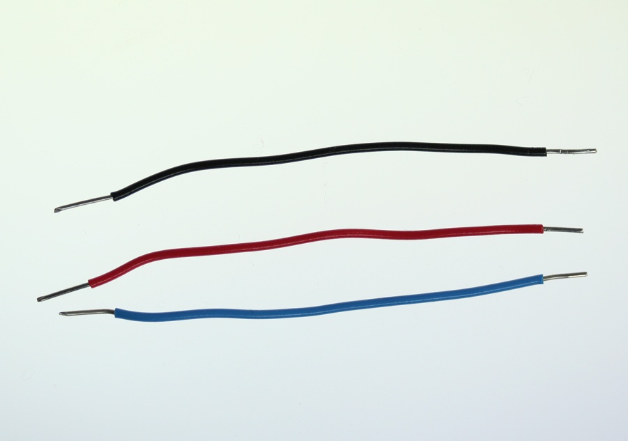
Connect power and ground on the breadboard to power and ground from the microcontroller. On the Arduino module, use the 5V and any of the ground connections(Figure 4):
As shown in Figure5, the +3.3 volts and ground pins of the Arduino are connected by red and black wires, respectively, to the left side rows of the breadboard. +3.3 volts is connected to the left outer side row (the voltage bus) and ground is connected to the left inner side row (the ground bus). The side rows on the left are connected to the side rows on the right using red and black wires, respectively, creating a voltage bus and a ground bus on both sides of the board.
Related Video: DIY Serial protocol
Connect an LED and resistor to pin 11 of the Arduino through a 220-ohm resistor. If you prefer an audio output, you can use a speaker instead. Appropriate code changes will be mentioned below (Figure6-7):
Figure 8: Breadboard view of an LED connected to digital pin 5 of an Arduino Nano. The Nano straddles the center of the breadboard in the first fifteen rows. The Nano’s voltage pin (physical pin 2) connects to the board’s voltage bus, and the Nano’s ground pin (physical pin 14) connects to the board’s ground bus. The LED is in the right center of the board, with its anode in one row and the cathode in the next. A 220-ohm resistor connects the LED’s anode to a wire connecting to digital pin 5. The LED’s cathode is connected to the ground bus.
Related Video: Serial.available()
To program the Arduino to read serial input, you use the Serial.available() command. The .available() command returns the number of bytes that are available in the Arduino’s serial buffer that you haven’t read yet. When there are bytes available, you can read them using Serial.read().
In the setup() function of your program, initialize serial communications using Serial.begin(). Set the LED’s pin to be an output using pinMode() as well. Then in the setup, check how many bytes are available in the serial buffer using Serial.available() like so:
void setup() {
  Serial.begin(9600);   // initialize serial communications
  pinMode(11, OUTPUT);  // set digital pin 11 to be an output, to control the LED
}

void loop() {
  if (Serial.available() > 0) {

  }
}
Related Video: reading the bytes in Arduino
Inside the if statement that checks Serial.available(), you’ll interpret the bytes as they come in. First, read the incoming bytes using Serial.read(). The serial buffer is a First-in, First-out buffer, or a FIFO buffer, meaning that the first byte that the computer sends is the first byte that the Arduino can read:
Here’s how to read the incoming bytes and interpret them:
void loop() {
  if (Serial.available() > 0) {
    byte input = Serial.read();  // read first available byte into a variable
    if (input == 'H') {          // if the variable equals H, or ASCII 72
      digitalWrite(11, HIGH);     // turn on the LED
    }
    if (input == 'L') {          // if the variable equals L, or ASCII 76
      digitalWrite(11, LOW);      // turn off the LED
    }
  }
}
This sketch now reads the first available byte into the variable input, then evaluates the variable. If input is equal to 72, which is the ASCII letter H, it turns on the LED. If input equals 76, or ASCII L, it turns the LED off.
In the C programming language (and by extension, in Arduino, since Arduino based on C), you can put a single ASCII character in single quotes and the compiler will interpret it as its numeric value. This can be handy when you know you want to compare a byte to an ASCII character, but can’t remember the numeric value of the ASCII character.
Related Video: uploading the sketch to the Arduino
Once you’ve uploaded this to the board, open the serial monitor. If you’re using the Arduino Serial Monitor to read and write serial data, make sure the line ending tab is set to “no line ending” like so(Figure 9):
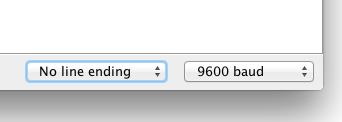
If you prefer to use a command line interface for serial communication, you can do that using the screen command.
Type H or L in the text input bar at the top, then hit enter. You should see the LED turn on when you send H, and turn off when you send L. You’ll notice that if you send lower case h or l, nothing happens. That’s because you didn’t check for those values. In ASCII, uppercase letters and lowercase letters each get different values. Uppercase H is 72, for example, but lowercase h is 104.
The serial monitor isn’t the only program that can send bytes to your microcontroller. Any program that can communicate over asynchronous serial communication can be used to send data. So if you’re using Processing, or Max/MSP, or node.js, you can control this simple Arduino program serially.
The microcontroller reads all incoming bytes as values from 0 to 255. In the example above, you saw how to interpret those values as ASCII characters. But you can use the byte values any way you wish. Change the loop of your program as shown below:
void loop() {
  // put your main code here, to run repeatedly:
  if (Serial.available() > 0) {
    byte input = Serial.read();
    // use the value of the incoming byte to control the LED's brightness:
    analogWrite(11, input);
  }
}
Upload this new sketch and open the serial monitor. When you send characters now, what’s happening? The LED’s brightness might be jumping around, seemingly randomly. Lower case letters toward the end of the alphabet will make the LED slightly brighter, and uppercase ones toward the beginning will make it dimmer. The lower the value, the lower the brightness of the LED. a space, which is ASCII 32, will make the LED very dim, while a tilde (~), which is ASCII value 126, will make it brighter.
Related Video: reading a byte from the computer in Arduino
But what if you want to send an ASCII-encoded numeric string? Why doesn’t the LED turn on to full brightness when you type “255”? Even though you interpret the characters as one number, the Arduino interprets them as three bytes, with the values 50 (“2” = ASCII 50), 53 (“5” = ASCII 53), and 53. How do you get the Arduino to convert these strings as numbers?
You can use the Serial.parseInt() function to interpret ASCII numeric strings. This function will read all incoming bytes looking for a numeric character, and when it finds one, it will keep looking until it finds the next non-numeric character. Then it will interpret all the numeric characters it found as one number. Change your sketch’s loop as follows:
void loop() {
  // put your main code here, to run repeatedly:
  if (Serial.available() > 0) {
    int input = Serial.parseInt();
    // use the value of the incoming byte to control the LED's brightness:
    analogWrite(11, input);
  }
}
Then send in a numeric string, like 255 or 10. You should see the LED get much brighter with 255, and much dimmer with 10. If you send 0, the LED should turn off. Instead of interpreting your data byte-by-byte, .parseInt() is looking for strings of numbers and interpreting them. You can even give it multiple strings separated by non-numeric characters. Try the following strings:
10,127,255 0 255 0 12-250-3
You can separate your numbers however you wish. You could even look for multiple different numbers with multiple variables, like this:
void loop() {
  // put your main code here, to run repeatedly:
  if (Serial.available() > 0) {
    int red = Serial.parseInt();
    int green = Serial.parseInt();
    int blue = Serial.parseInt();
  }
}
With the code above, if you sent three comma-separated values, you’d be able to set the three variables red, green, and blue independently.
You may notice that .parseInt() is slow to respond. It has a timeout that defaults to one second, waiting for incoming data. You can speed it up by using Serial.setTimeout() to set the timeout in milliseconds. In your setup, right after Serial.begin(), try a Serial.setTimeout(10) to set the timeout to 10 milliseconds. This is generally good for most programs that might be sending ASCII strings to the microcontroller.
If you’re familiar with node.js and the node-serialport library, perhaps because you’ve already tried the Serial to node.js lab, upload the following Arduino sketch:
void setup() {
  // put your setup code here, to run once:
  Serial.begin(9600);
  Serial.setTimeout(10);
  pinMode(11, OUTPUT);
}

void loop() {
  // put your main code here, to run repeatedly:
  if (Serial.available() > 0) {
    char input = Serial.parseInt();
    // use the value of the incoming byte to control the LED's brightness:
    analogWrite(11, input);
  }
}
Now try the following node.js script (you’ll need to install node-serialport using npm as you did in the Serial to node.js lab). Save this as serialOutput.js:
// serial port initialization:
var SerialPort = require('serialport'); // include the serialport library
var portName = process.argv[2]; // get the port name from the command line
var myPort = new SerialPort(portName, 9600);// open the port

// these are the definitions for the serial events:
myPort.on('open', openPort); // called when the serial port opens

function openPort() {
  var brightness = 0; // the brightness to send for the LED
  console.log('port open');
  console.log('baud rate: ' + myPort.options.baudRate);

  // since you only send data when the port is open, this function
  // is local to the openPort() function:
  function sendData() {
    // convert the value to an ASCII string before sending it:
    myPort.write(brightness.toString());
    console.log('Sending ' + brightness + ' out the serial port');
    // increment brightness by 10 points. Rollover if < 255:
    if (brightness < 255) {
      brightness+= 10;
    } else {
      brightness = 0;
  }
}

// set an interval to update the brightness 2 times per second:
setInterval(sendData, 500);
}
Make sure the serial monitor in Arduino is closed, then run this by typing the following on the command line:
$ node serialOutput.js portname
Replace portname with the name of your serialport. When this runs, you should see the LED getting ten percent brighter every half a second, then go out when it reaches the brightest.
Related Video: Intro to Synchronous Serial
Asynchronous serial communication, which you can see in action in the Serial Output lab, is a common way for two computers to communicate. Both computers must have their own clock, and keep time independently of each other. This works well for personal computers, mobile devices, and microcontrollers because they all have their own clock crystal that acts as the processor’s heartbeat. However, there are simpler integrated circuits that have only one function, such as to read a sensor or to control a digital potentiometer or an oscillator to drive a PWM circuit. These ICs have no clock crystal of their own. They consist of a few memory registers and the minimal circuitry needed to connect these memory registers to the circuit that they control. To communicate with these ICs, you need to use synchronous serial communication.
To get the most out of these notes, you should know what a microcontroller is and have an understanding of the basics of microcontroller programming. You should also understand the Asynchronous Serial Communication: The Basics as well.
Synchronous serial communication protocols feature a controller device which sends a clock pulse to one or more peripheral devices. The devices exchange a bit of data every time the clock changes. There are two common forms of synchronous serial, Inter-Integrated Circuit, or I2C (sometimes also called Two-Wire Interface, or TWI), and Serial Peripheral Interface, or SPI.
Synchronous serial devices communicate by shifting bits of data along their communication lines, like a bucket brigade. Data moved down the line one bit every time the clock pulses. All the devices in a synchronous serial chain share the same data and clock lines. Peripheral devices are directed by the controller device when to listen to the bits coming down the line, and when to ignore them. However, the two most common synchronous serial protocols, SPI and I2C, use different methods for directing the peripheral devices.
Related Lab: SPI Communication With A Digital Potentiometer
SPI devices are connected by four wires, as shown in Figure 1:
The electronics industry has used the terms “master/slave” to refer to controller devices and peripheral devices for decades without regard for the historical context of, and offense caused by, those terms. As a result, you will see the terms MOSI/MISO/SS in data sheets to refer to the pins of an SPI device. While a modern standard naming scheme has not yet emerged to replace these, the Open Source Hardware Association has a proposal on the table. Make Magazine proposes retaining the acronym while renaming the terms. The SDO, SDI and CS terms are currently used by a handful of companies within the industry, but have some ambiguity when used in practice. Hence, the PICO/POCI proposal. The debate is not resolved, and you will likely see some variations on the terms. The SDO, SDI, and SCK terms are the most widely accepted terms that do not carry historical baggage.
The SDI, SDO, and SCLK connections are shared between all the devices connected to the controller. This configuration is called a bus. Each peripheral has its own dedicated Chip Select connection to the controller, however.
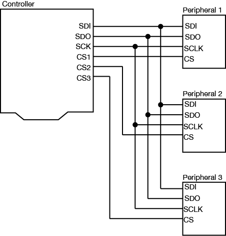
When the controller device wants to communicate with one of the peripherals, it sets that device’s Chip Select pin low. The peripheral will then listen for new bits of data on the microcontroller’s Serial Data Out (SDO) line every time the clock changes from low to high (called the rising edge of the clock). If it is instructed to send any data back, it will send data back to the controller when the clock signal changes from high to low (called the falling edge of the clock). When a peripheral device’s Chip Select pin is high, it will not respond to any commands sent on the data line.
The data exchange between SPI devices is usually shown like this (Figure 2):
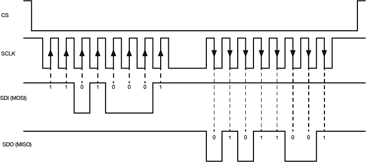
The Arduino’s SPI pins are determined by the processor. You can find the pins for the various models on the SPI library reference page. For the Arduino Uno, the pin numbers are pin 11 for SDO, pin 12 for SDI, and pin 13 for Clock (SCK). Pin 10 is the default Chip Select pin (SS), but you can use other pins for Chip Select as needed. The Arduino SPI library allows you to control the SPI bus. Most SPI devices that are compatible with Arduino come with their own libraries, however, which wrap the SPI library in commands specific to the device in question.
For example, the Analog Devices ADXL345 accelerometer can communicate via SPI. Its protocol works as follows: first the controller sets the ADXL345’s Chip Select (CS) pin low, then sends a command to the ADXL345 on the SDI line to enter measurement mode. The ADXL345 then continually samples the accelerometer and stores the latest readings in three memory registers. When the controller wants to know those values, it sets the Chip Select (CS) pin low and sends a request to read those memory registers. The ADXL345 responds by sending back the contents of the memory registers on the SDO line. When all the data has been received, the controller sets the Chip Select pin high again.
The advantage of SPI is that the data transactions are simple: all you need to do is to send the data to the device you’re communicating with. The disadvantage is that the number of wires needed to connect goes up by one for every peripheral device you add to the bus.
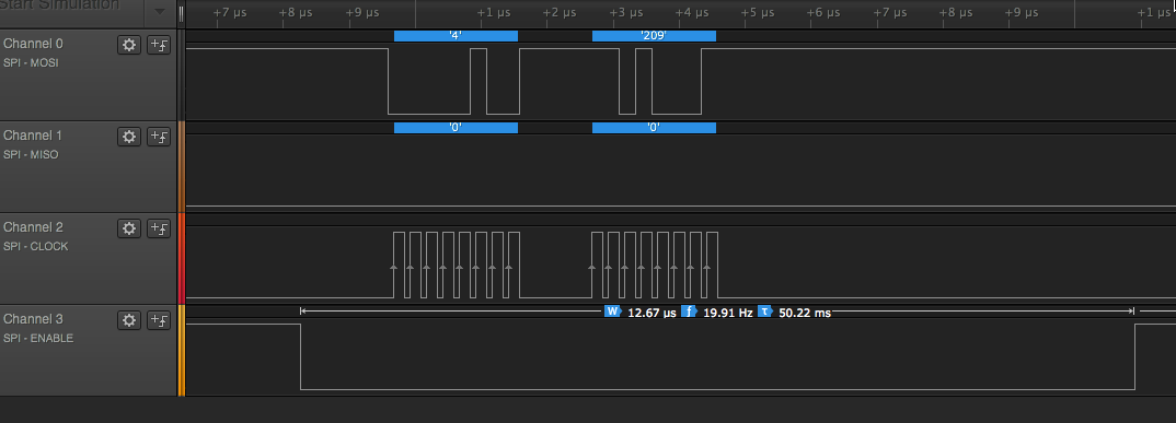
Related Lab: I2C Communication With An Infrared Temperature Sensor
I2C is another popular synchronous serial protocol. It also uses a bus configuration like SPI, but there are only two connections between the controller device and the peripheral devices as shown in Figure 4:
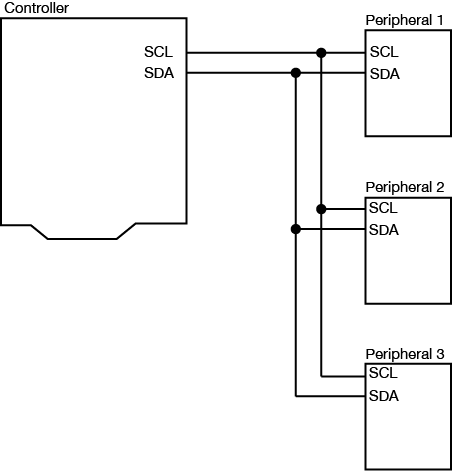
Each I2C peripheral device has a unique address on the bus. When the controller wants to communicate with a particular peripheral, it sends that peripheral’s address down the SDA connection, transferring each bit on the rising edge of the clock. An extra bit indicates whether the controller wants to write or read to the peripheral that it’s addressing. The appropriate peripheral then goes into listening mode, and the controller sends a command to the peripheral. Then the controller switches its connection to the SDA line from output to input. The peripheral then replies with the appropriate data, sending each bit on the falling edge of the clock. The controller switches its connection on the SDA line back to output once it’s received all of the data.
The I2C data capture in Figure 5 is typical (click to enlarge it). This is from a Texas Instruments TMP007 temperature sensor. The peripheral’s address is 0x40. First the controller sends a byte with 0x40 + 0 in the final bit, indicating that it plans to write a command to the peripheral. All of this data is sent valid on the rising edge of the clock. Then the controller sends a command, 0x03, which means “tell me your object’s temperature” to this particular IC. Then the controller sends a byte with the peripheral’s address again, 0x40 +1 in the final bit, indicating that it wants to read from the peripheral. The peripheral responds with two bytes, 0x0B and 0xC0. The controller then puts those two bytes together to get the object’s temperature (see the TMP007 datasheet if you want to know more)
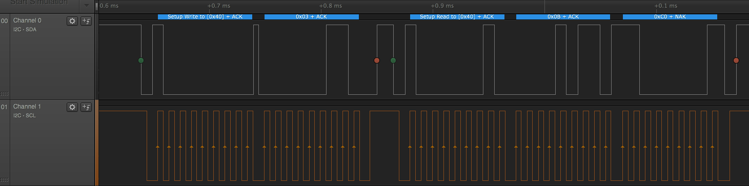
The Arduino’s I2C pins are determined by the processor. You can find the pins for the various models on the Wire library reference page. The Arduino Wire library allows you to control the I2C bus. For the Arduino Uno, the pin numbers are analog pin 4 for SDA and analog pin 5 for SCL. On the Uno rev.3 layout, SDA and SCL are also broken out on the digital side of the board, next to the ground pin. Most I2C devices that are compatible with Arduino come with their own libraries which wrap the Wire library in commands specific to the device in question. For example, Adafruit‘s library for the TMP007 relies on the Wire library to transmit and receive data.
You can also use I2C as a way to control many microcontrollers from one central controller. For example, if you needed to operate a large number of servomotors, you could put five or six each on a single Arduino, then chain several Arduinos together in an I2C chain and program them all to respond as peripherals. Then you would program a central microcontroller as the controller, and have it send commands to the peripheral devices when it’s time to move each device’s servos. You can see an example of how to do this in this example from the Arduino site.
In addition to the standard I2C connections, Sparkfun and Adafruit use a connector called Qwiic which connects the I2C and power connectors all in one cable, eliminating the need for soldering. It’s a Sparkfun brand name. However, you’ll need a Qwiic adapter shield to use it. Adafruit have a similar brand called Stemma, Seedstudio uses Grove, and DFRobot uses Gravity. They all support I2C, and they all have custom solderless connectors, though they are not all compatible with each other Qwiic, Stemma, and Arduino’s Modulino connectors work pretty well together, though. For an example of Qwiic connectors in action, see this lab introducing the Nano Qwiic shield.
SPI and I2C are useful protocols because they allow you to interface with a wide variety of sensor and actuator ICs without having to use many of your microcontroller’s IO pins. Because they are both bus protocols, you can chain many devices on the same bus, and call on them only when needed from your microcontroller. For more on their usage, see the Lab: SPI Communication With A Digital Potentiometer and the Lab: I2C Communication With An Infrared Temperature Sensor.
In this lab you’ll connect a microcontroller to a web browser using the node.js programming environment, HTML, and JavaScript.
You can write programs that handle serial communication in many different languages. This page introduces how to do it using node.js. Node is a JavaScript environment that allows user to write web server programs. Below, you’ll use it to connect a microcontroller to a web browser using the node.js programming environment, HTML, and JavaScript.
To get the most out of this tutorial, you should know what a microcontroller is and how to program a microcontroller. You should also understand asynchronous serial communication between microcontrollers and personal computers. You should also understand the basics of command line interfaces.
You will struggle with this tutorial if you aren’t familiar with JavaScript. For more on JavaScript, see Douglas Crockford’s JavaScript: The Good Parts, Manuel Kiessling’s the Node Beginner Book, or Shelley Powers’ Learning Node.
The current version of this tutorial works with version 6.x.x of the node-serialport library.
This node.js introductory video will help in understanding this lab. The code in the video is different than this lab, but the basic concepts are similar. This lab simplifies the process a bit.
The JavaScript programming language is mainly used to add interactivity to web pages. All modern browsers include a JavaScript interpreter, which allows the browser to run JavaScript code that’s embedded in a web page. Google’s JavaScript engine is called v8, and it’s available under an open source license. Node.js wraps the v8 engine up in an application programming interface that can run on personal computers and servers. On your personal computer, you run it through the command line interface.
Node was originally designed as a tool for writing server programs, but it can do much more. It has a library management system called node package manager or npm that allows you to extend its functionality in many directions. There is also an online registry of node libraries, npmjs.org. You can download libraries from this registry directly using npm. Below you’ll see npm used to add both serial communication functionality and a simple server programming library to node.
To get started, download the node.js installer and install it on your computer. Then open your command line terminal. On OSX, open the Terminal app, which can be found in the Applications/Utilities directory. On Windows, go to the start menu and type cmd then press enter to open a window to the command line.
If you’ve never used a command line interface, check out this tutorial on the Unix/Linux command line interface. From here on out, you’ll see the command prompt indicated like this:
yourname@yourcomputer ~ $
Any commands you need to type will follow the $ symbol. The actual command prompt will vary depending on your operating system. On Windows, it’s typically this: >. On most Unix and Linux systems, including OSX, it’s $ or %.
When you’ve installed node.js, type this command at the command prompt to get the version of node that you’re running:
$ node -v
If you installed it correctly, you’ll get a version number like 12.18.0. The node installer should also install the node package manager (npm). You can check that in the same way:
$ npm -v
Once node and npm are in place, you’re ready to create a new project.
Related video: Install the serialport Node module
There’s a library for node.js that allows you to communicate over your computer’s serial ports called serialport. If your computer’s connected to the internet, you can download install it automatically using npm. Create a new directory for your project:
$ mkdir nodeSerialExample
Then change directories to that directory:
$ cd nodeSerialExample
Now make a new text file in that directory with the name index.js.
This will be your main program file. Add the following text to the file:
console.log("Hello, and welcome to node.");
Save the file, then run it by typing the following on the command line:
$ node index.js
Your program should print out:
Hello, and welcome to node.
The program will finish and return to the command line when it’s done. Seeing that script running is indication that node.js is fully working on your machine.
You can also pass information into your node program using the process arguments on the command line. Change your program like so:
var name = process.argv[2];
console.log("Hello, and welcome to node," + name);
Run this as you did before, but add your name after the name of your program when you invoke it, like so:
$ node index.js Tom
You’ll get the following:
Hello, and welcome to node, Tom
The command line arguments are passed to your program as an array. The name was the third word you typed, or array element 2 (counting “node” as element 0 and “index.js” as element 1). This is a useful technique, and you’ll see it later to pass the program your serial port’s name.
You’ll also need the node serialport library, which you can install from the npm registry like so:
$ npm install serialport
This command will make a new subdirectory called node_modules, and in that directory it will install all the necessary assets for the serialport library. You’ll see a lot of text go by, and hopefully no errors. If you get errors, consult npmjs.org and the github wiki for serialport. Now you’re ready to use the serialport library.
The first thing you’ll want is a list of the serial ports. Replace the text of your program file with the following:
let serialport = require('serialport');

// list serial ports:
serialport.list().then (
  ports => ports.forEach(port =>console.log(port.path)),
  err => console.log(err)
)
If you’re new to JavaScript, this syntax may be confusing. Node.js examples tend to use anonymous functions frequently. JavaScript can pass functions as variables (and vice versa). This is also using the JavaScript ES6 arrow function notation. That’s what’s going on here.
Stoyan Stefanov’s JavaScript Patterns is useful for understanding the various patterns of JavaScript coding.
When you run this script, you’ll get a list of your serial ports like so:
$ node ListPorts.js
/dev/cu.Bluetooth-Incoming-Port
/dev/cu.Bluetooth-Modem
/dev/cu.usbmodem1411
If you’ve got an Arduino plugged in via USB, you should see the name of your board’s port there as well. In the example above, which was run on OSX, the Arduino’s port is /dev/cu.usbmodem1411.
The process of using the serialport library will be the same every time:
Which are all explained below.
To open a serial port in node, you include the library at the beginning of your script, and make a local instance of the library in a variable. Make a new script or replace index.js with the following:
let serialport = require('serialport');// include the library
// get port name from the command line:
let portName = process.argv[2];
Then you open the port using new() like so:
let myPort = new SerialPort(portName, 9600);
Note the serial parameters, which are passed to the new() function after the port name, as a list. The only one used here is the baud rate, set to 9600 bits per second.
If you want to read serial data as ASCII-encoded text, line by line, you also need to create a parser to tell the serial library how to interpret data when it comes in. It should read all the incoming data as a line of text, and generate a new data event when it sees a newline (“\n”). The parser is doing the same thing as Processing’s Serial.bufferUntil() function does. You do it like so:
let Readline = SerialPort.parsers.Readline; // make instance of Readline parser
let parser = new Readline(); // make a new parser to read ASCII lines
myPort.pipe(parser); // pipe the serial stream to the parser
You can find the full program so far at this link.
When you run this program now, it won’t automatically stop and return to the command line. To stop it, you’ll need to type control-C in the terminal window to stop it. The new instance of Serialport created a software object that listens for events from the serial port. Any node.js script that creates an event listener like this will run until you explicitly stop it. Both the serialport library and the http library, which you’ll use below, generate event listeners and will need to be explicitly stopped using control-C.
The serialport library, like most node.js libraries, is event-based. This means that when the program is running, the operating system and the user’s actions will generate events and the program will provide functions to deal with those events called callback functions.
The main events that the serial library will deal with are when a serial port opens, when it closes, when new data arrives, and when there’s an error. The data event in particular performs the same function as Processing’s serialEvent() function. Once you’ve made an instance of the serialport library using the new() function as shown above, you define what functions will get called when each event occurs by using serialport.on() like so:
myPort.on('open', showPortOpen);
parser.on('data', readSerialData);
myPort.on('close', showPortClose);
myPort.on('error', showError);
The functions that are called by the event are the callback functions. In the example above, when the serial port is opened, the showPortOpen function will get called. When new data arrives, the sendSerialData function will get called, and so forth. If the event generates any parameters (for example a new data event will have the data as a parameter), those parameters will get passed to the callback function.
In the example above, you’re listening for the open, close, and error events using functions from the serial port object (e.g. myPort.on('open', showPortOpen);), but you;’re listening for the data event using a function from the parser object (parser.on('data',readSerialData);). You can listen with the serial port object too (e.g.myPort.on('data',readSerialData);), but the port object listener function generates a data event once every byte, while the parser object lets you generate a data event once every newline instead.
Write the callback functions for these events like so:
function showPortOpen() {
  console.log('port open. Data rate: ' + myPort.baudRate);
}

function readSerialData(data) {
  console.log(data);
}

function showPortClose() {
  console.log('port closed.');
}

function showError(error) {
  console.log('Serial port error: ' + error);
}
Now you’ve got enough of a program to see some results. Upload a simple serial output sketch to your Arduino such as the AnalogReadSerial example or the sketch shown in the Analog Input Lab, you’ll be able to see its output from this script. Save the script. Then invoke it as follows, replacing portname with the name of your serial port:$ node index.js portname
For example, on OSX, if you haven an Arduino attached to the serial port called /dev/cu.usbmodem1411, then you’d type:
$ node index.js /dev/cu.usbmodem1411
When the port opens, you’ll see the message from the showPortOpen() function, then the output from the Arduino. Here’s the output from the node script:
port open. Data rate: 9600

266
276
261
To send serial output from node.js to the Arduino, use the serialport write() function like so:
myPort.write("Hello");
That’s all it takes to read and write serial data from node.js to a microcontroller. Node.js is designed for writing web server applications, however, so in the following steps you’ll see how to connect a serial port to your web browser using more of node.js.
In order to connect your node.js program to a web page, your program needs to listen for messages from the web browser, and the web pages need to connect to the program. To do this, you’ll use a connection called a webSocket. WebSockets are connections between web clients and servers that function a bit like serial ports. Both serial connections and webSocket connections are data streams, in which the first byte sent into the stream on one end is the first byte read out on the other end. Data streams are common programming structures and you’ll see them used in lots of places. They connect programs to files on your computer, or client programs to server programs, or desktop programs to serial or network ports. The diagram below(Figure 1) shows how the browser connects to your node.js program and how the node.js program connects to the serial port.
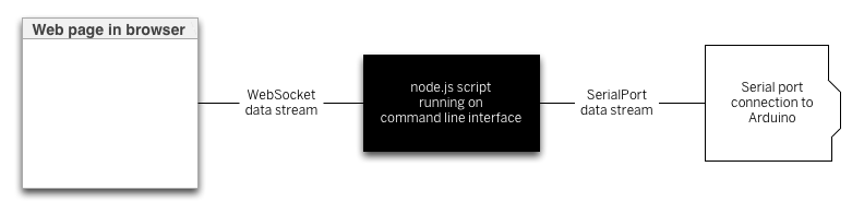
There’s a node.js library your script will need to listen for webSocket connections that you should install using the node package manager like so:
$ npm install ws
Once it’s successfully installed, include it with your previous script by adding the following at the beginning of the script, right after you included the serialport library:
let WebSocketServer = require('ws').Server;
Following that, you need to use new() to make a new instance of the webSocket servver, and then configure a few parameters, and finally start the server:
const SERVER_PORT = 8081;               // port number for the webSocket server
let wss = new WebSocketServer({port: SERVER_PORT}); // the webSocket server
let connections = new Array;          // list of connections to the server
The server will operate on port 8081, so when you write a client-side JavaScript program, you’ll connect to that port number. Your browser will be a client of the node.js script, and the script will be running as a server. Just as there are serialport event listener functions, there will be webSocket event listener functions too. You’ll need to listen for a webSocket connection event, and once connected, you’ll need to listen for incoming messages, and for the webSocket to close.
There can be multiple webSocket clients at any one time, so the server maintains an array to keep track of all the clients. That array is called connections, and every time a new client connects, the client is added to the array using the .push() function. When a client closes, it’s removed from the array using the .slice() function.
Here are the webSocket event listeners:
wss.on('connection', handleConnection);

function handleConnection(client) {
  console.log("New Connection"); // you have a new client
  connections.push(client); // add this client to the connections array

  client.on('message', sendToSerial); // when a client sends a message,

  client.on('close', function() { // when a client closes its connection
    console.log("connection closed"); // print it out
    let position = connections.indexOf(client); // get the client's position in the array
    connections.splice(position, 1); // and delete it from the array
  });
}
You’ll also need to modify the serialport data event listener to send data to the webSocket, and vice versa. Here’s a function to send webSocket data to the serial port. Put this after the serial event listeners above:
function sendToSerial(data) {
  console.log("sending to serial: " + data);
  myPort.write(data);
}
To parallel that, here’s a function to send serial data to the webSocket clients. Put this after the webSocket event listeners:
// This function broadcasts messages to all webSocket clients
function broadcast(data) {
  for (myConnection in connections) {   // iterate over the array of connections
    connections[myConnection].send(data); // send the data to each connection
  }
}
Finally, you need to add the highlighted lines below to the readSerialData() function. This will send the latest data to all available webSocket clients:
function readSerialData(data) {
  console.log(data);
  // if there are webSocket connections, send the serial data
  // to all of them:
  if (connections.length > 0) {
    broadcast(data);
  }
}
Now you’ve got a complete script for connecting serial data to a webSocket server, and serving that to a client through a browser. Next you need a web page with its own embedded JavaScript to connect to his script.
The real value in connecting the serial port to a server is to generate dynamic HTML from the sensor data. You can do this by making an HTML page that includes some JavaScript to request data from the server, and serving that HTML page from a directory called public in your project directory. First, create the directory and change directory into it:
$ mkdir public
$ cd publicThen create a new document, index.html, in this directory. Don’t enter any elements, just the bare skeleton of a page:
<!DOCTYPE html>
<html>
<head>
  <meta charset='utf-8'>
  <title>Hello</title>
</head>
<body>

</body>
</html>
If you’re used to Processing, then P5.js is a really good way to get started with JavaScript in the browser. It gives you the same structure as Processing, but in JavaScript. To use it, you’ll need to include P5.js using script tags in the head of your HTML.
First, you need to include p5.js in the document head. You can either download P5.js and its libraries directly, or you can include them from p5.js’s content delivery site, as shown in the HTML below.
Create a file called sketch.js in the same directory as your HTML file. This is where you’ll write your JavaScript, using the p5.js library.
p5.js uses setup() and draw() methods, just like Processing, and similar to Arduino. You’re going to use it to create an HTML text div element in the document, and when you receive serial data, you’ll use it to set the text and the position of the text element. Start with the setup() and draw() and global variables for the text element and a webSocket connection like so (from here on out, the rest of the HTML will be omitted for brevity. Everything you see below will be done in the sketch.js file. Here’s the final HTML:
<!DOCTYPE html>
<html>

<head>
  <script type="text/javascript" src="https://cdnjs.cloudflare.com/ajax/libs/p5.js/1.0.0/p5.min.js"></script>
  <script type="text/javascript" src="sketch.js"></script>
</head>

<body>
</body>

</html>
Start the sketch.js file by making webSocket that will listen on port 8081. Then add the p5.js setup() and draw() functions:
let text;		// variable for the text div you'll create
let socket = new WebSocket("ws://localhost:8081");

function setup() {
}

function draw() {
}
In the setup() function, add listeners for the webSocket, and create the text div and position it. You’ll write the listener functions a bit later:
function setup() {
  // The socket connection needs two event listeners:
  socket.onopen = openSocket;
  socket.onmessage = showData;

  // make a new div and position it at 10, 10:
  text = createDiv("Sensor reading:");
  text.position(10,10);
}

function draw() {
}
Next, write the openSocket() listener and showData functions which are the callback functions for the webSocket’s event listeners:
function openSocket() {
  text.html("Socket open");
  socket.send("Hello server");
}

function showData(result) {
  // result is a JSON string. Parse it:
  let input = JSON.parse(result.data);
  // when the server returns, show the result in the div:
  text.html("Sensor reading:" + input);
  xPos = int(input);        // convert result to an integer
  text.position(xPos, 10);        // position the text
}
This last function changes the text inside the div. It also moves the div’s horizontal position. Whenever new data arrives from the server, this function will be called automatically, so there’s no need for a draw() function. Save this file in the public directory, then restart the server and open the file in your browser. You should see the text moving across the screen left to right, depending on the sensor, as in the video below. When the sensor value is high, its text representation will be to the right in the browser. When it’s low, it will be to the right in the browser:
browser-animation from ITP_NYU on Vimeo.
There is no soundtrack to this video.
Once you’ve got a server program serving data from a serial device to a browser, you have potential to make all kinds dynamic interfaces that combine HTML and physical interfaces. Notice that the server program doesn’t actually parse the serial data; it just treats it as a string, and passes that string on to the client. The client does any parsing work; in this case, converting the numeric string to an integer. This means you can keep the server very simple, so you only need to make sure the two endpoints (the microcontroller and the web client) are speaking the same protocol. JavaScript has many functions for manipulating strings, particularly comma-separated values. So consider sending your data from Arduino as comma-separated values.
When p5.js returns the result of a request, it returns the string as an array with one element. If you’re planning on manipulating that string with functions like parseInt(), split() and other string handling functions, make sure to get the string out of the array first. For example, if you’ve sent over the string:
"234, 124, 134"
and you want to split it, here’s how you’d do it:
function showData(result) {
  var resultString = JSON.parse(result.data);
  text.html("Sensor reading:" + resultString);
  // split it:
  var numbers = split(resultString, ",");
  // use the numbers:
  text.position(int(numbers[0]), int(numbers[1]));
  text.style("font-size", int(numbers[2]) + "%");
}
Because the wsServer.js script passes through messages through without parsing, you can add handshaking to this application by modifying only the Arduino program and the P5.js script. When you add handshaking the Arduino will only send new data when it receives a byte of data in the serial port. It allows you to control the flow of data better.
To implement handshaking, make the following change in the Arduino sketch. Wrap the contents of the loop() in the Arduino sketch in an if statement like so:
void loop() {
  if (Serial.available()) {
    char input = Serial.read();
    // read the input on analog pin 0:
    int sensorValue = analogRead(A0);
    // print out the value you read:
    Serial.println(sensorValue);
    delay(1); // delay in between reads for stability
  }
}
Then add the following line to the end of the showData() function in your p5.js sketch:
function showData(result) {
  // result is a JSON string. Parse it:
  let input = JSON.parse(result.data);
  // when the server returns, show the result in the div:
  text.html("Sensor reading:" + input);
  xPos = int(input);        // convert result to an integer
  text.position(xPos, 10);        // position the text
  socket.send('a');        // send a byte to get the Arduino to send new data
}
You won’t need to change the wsServer.js script at all. Just restart it after you upload to the Arduino, and reload the page in the browser. When the client connects to the server, it will send the “Hello” message, which will be sent from the server to the Arduino, and that will trigger the Arduino to start sending data.
For more info:
A more complete set of code for this lab can be found on gitHub.
If you’ve never programmed before, there are a few terms and concepts that may throw you off when you first start. There are many helpful guides to understanding programming on the web, and there are many for Arduino, p5.js, and Processing in particular. What follows are some specific concepts that will come up in these labs and notes that you may not be familiar with.
To get the most our of these notes, you may want to download Arduino and try things as they’re mentioned.
In order to write a computer program, whether it’s for the computer on which you’re currently working or for a microcontroller, or for a web server, you need a programming environment. This usually consists of a few components:
All of these combined make up what’s called an Integrated Development Environment or IDE. When you hear about the Arduino IDE and the p5.js Editor or any other IDE (such as Processing), you can assume that it’s an application that’ll include at least these pieces, if not more.
The text editor of any IDE is the main thing you should see. It’s where you write your code. Programming text editors can come with all kinds of features. The Arduino editor, the p5js editor, and the Processing editor are all pretty basic so as not to overwhelm you with features, but there are a couple features you might notice:
Line numbers are displayed at the bottom of the editor as shown in Figure 1. In later versions of Arduino (1.6.5 and after) you can click on File -> Preferences and turn on line numbering in the editing window itself.
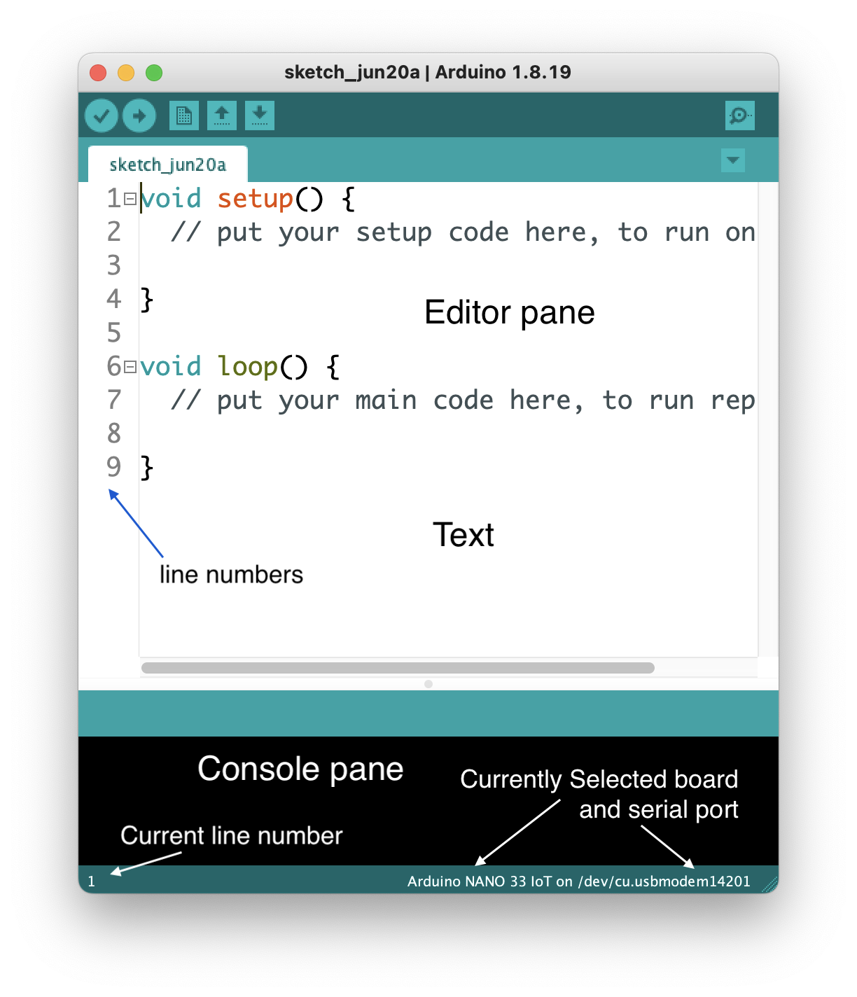
The console pane at the bottom of the editor is where the IDE will send you messages. They may be error messages, or they may be messages that you programmed into your sketch. Below, you can see two messages: Figure 2 tells you that your code successfully compiled, and Figure 3 tells you that the IDE couldn’t find your Arduino:
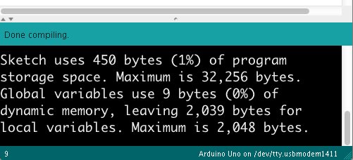
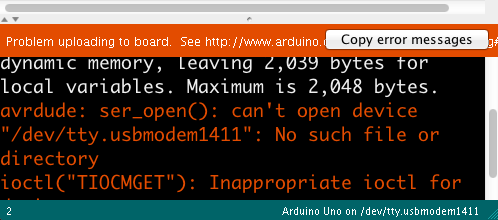
Block completion indicators Many programming languages use braces {}, parentheses () and brackets [] as punctuation for parts of a program. Programming editors usually include an indicator that shows you the opening or closing bracket, parenthesis, or brace that goes with the one on which the cursor is currently positioned. In Figure 4 you can see the rectangle around the opening bracket that is paired with the closing bracket where the cursor is. Put your cursor on different brackets, braces, or parentheses, and you should see this completion indicator move.
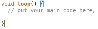
The Toolbar contains the control buttons that give you control of the compilation and upload of your code. In Arduino (Figure 5), the first button to the left compiles your code and the second compiles and uploads to the board you have selected. The next few buttons are for opening and saving files. The one on the right opens the Serial Monitor:
In p5.js and Processing, the toolbars are a little different as shown in Figure 6 and Figure 7. There’s no upload button because the code runs right on the web or your laptop respectively. But there are start and stop buttons instead. There’s no Serial Monitor button because messages in your code appear in the Console or Message Pane instead, and in Processing there is a button for exporting your code as a finished application, and a mode selector menu for choosing the programming mode:
Serial Monitor The Arduino IDE includes monitor program that watches any data coming in the serial port from your Arduino board, and allows you to send data out to the board. Figure 8 show a serial monitor of the Arduino IDE. You can print out anything you want to the Serial Monitor using Serial.print() and Serial.println() and Serial.write() commands. and see what your program is doing. This is a rudimentary debugging tool, but a useful one. The equivalent in p5js is the Console, where your print() or console.log() messages will appear. Processing’s equivalent is the Message Pane, where your println() messages appear.
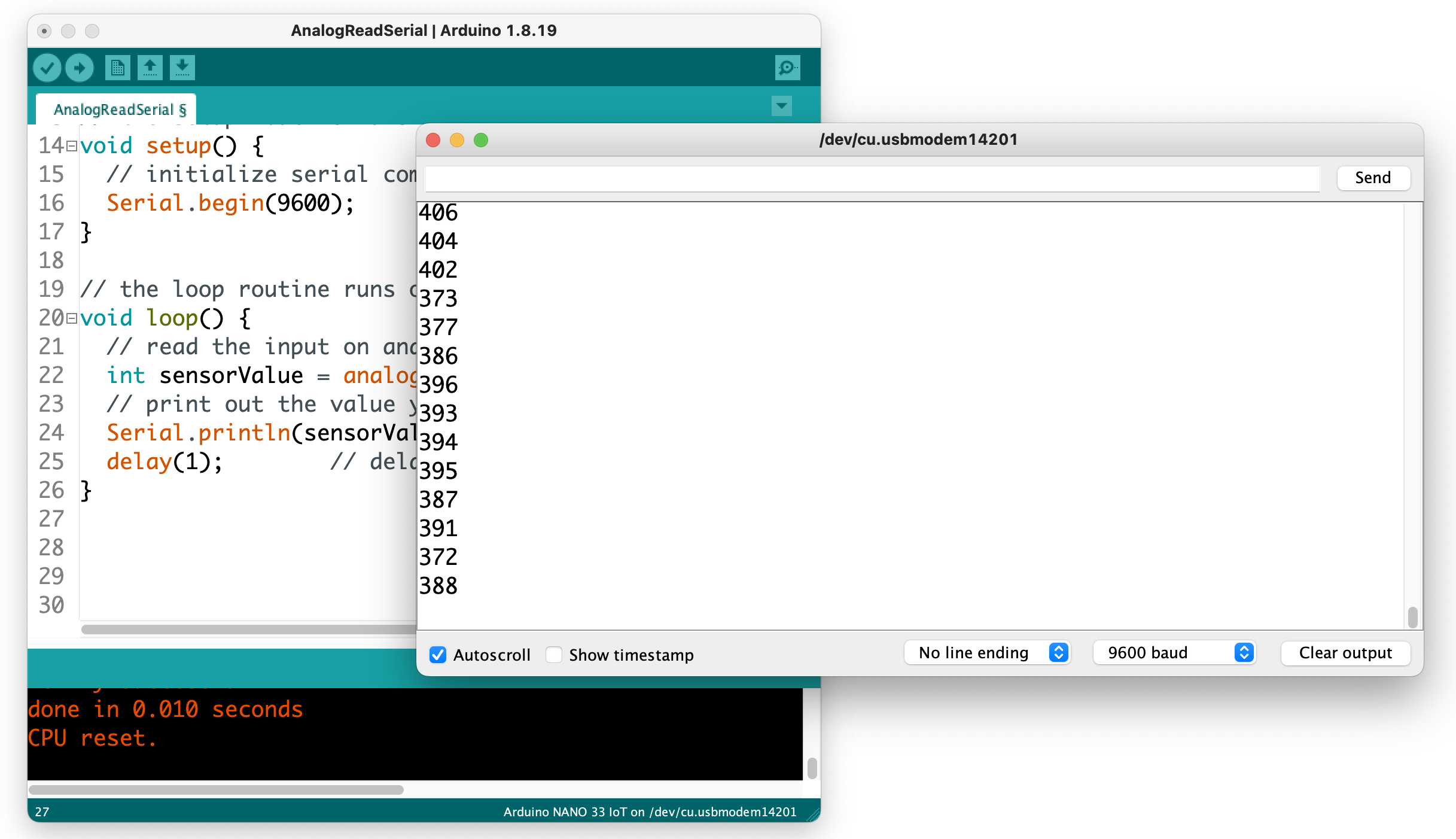
A new version of the Arduino desktop IDE is in development, and as of version 2.0.0-rc7, it’s stable enough for class use. You can stay with the earlier version (1.8.19) if you prefer, but if you want to use 2.0.0, here are some differences to note:
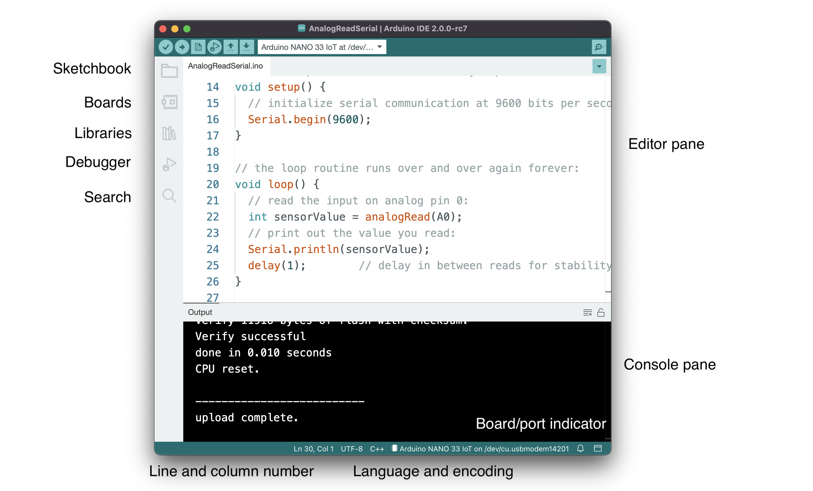
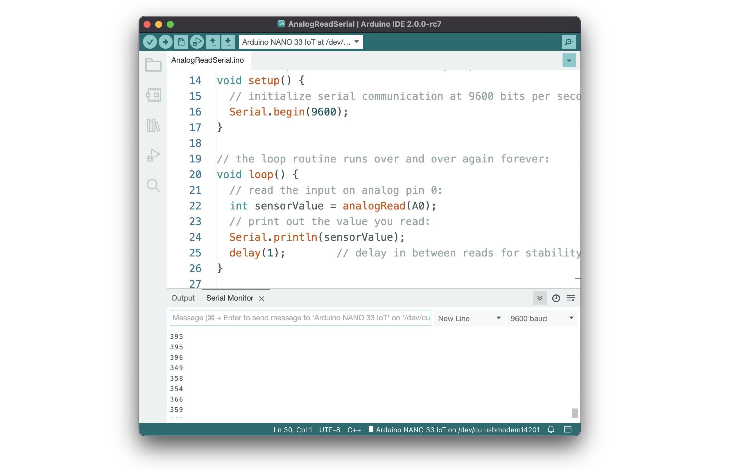
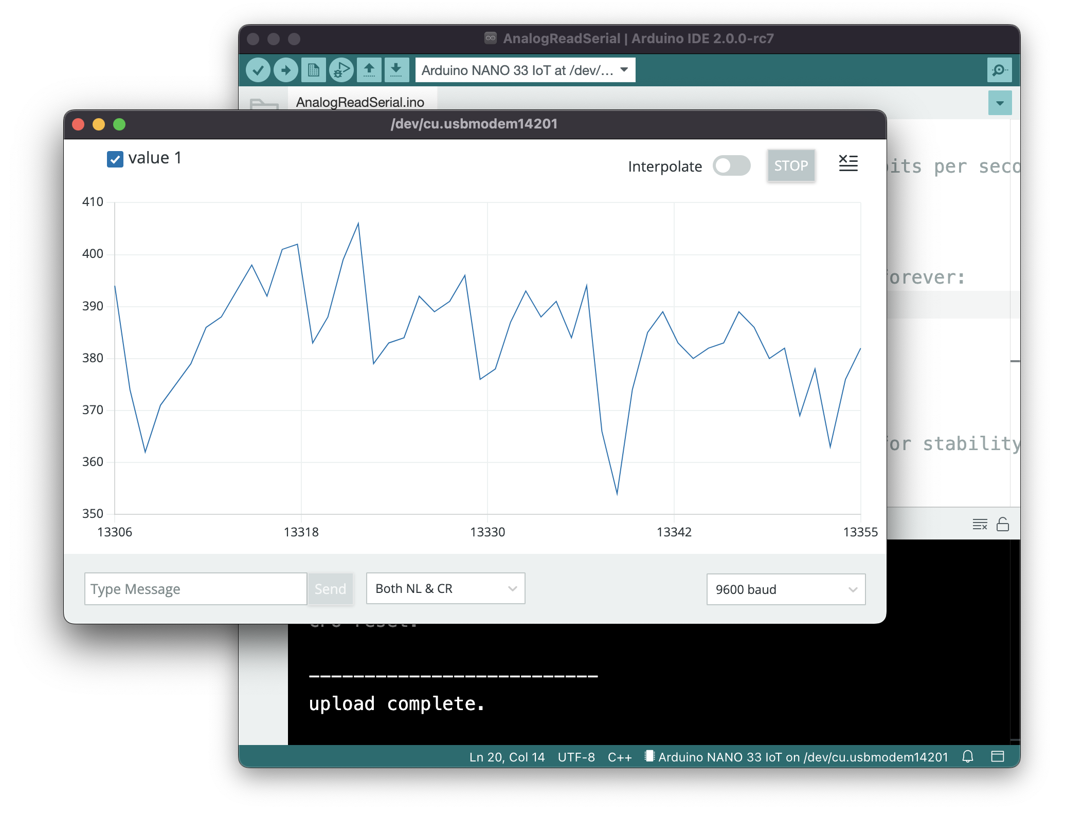
The compiler is a program that takes the text you write and translates it into the binary instructions that the computer needs to run the program. You never actually see the compiler in the Arduino or Processing IDEs, because it does all the work in the background. The buttons in the Toolbar are your interface to the compiler, and the message pane is where you’ll see status and error messages from it.
The Arduino IDE, and any other microcontroller IDE, will also include an uploader, which moves the compiled code from your personal computer to the microcontroller itself. Other microcontroller environments may require a hardware programmer which attaches to your computer via USB and then connects to your controller in order to upload the code to it.
Programming languages have a syntax, just like written languages. Understanding the terms for that syntax will make it easier to program. Arduino is based on a programming language called C, and Processing is based on a programming language called Java. There are many programming languages that share the same basic syntax as C, and they’re referred to as C-style languages. Java happens to be a C-style language, as is JavaScript. The notes below all describe C-style languages, so it all applies to C, Java, Arduino, Processing, and JavaScript, among others.
Variables are the constructs that programming languages use to store changing information in a program. In C-style languages, every variable must be declared before you use it, by giving it a name and a data type. You usually give it an initial value as well, like so:
buttonPushes = 0;
Variables can generally be any word you want, as long as they don’t start with a number, and as long as they’re not an existing keyword in the language. It’s helpful if you use descriptive variable names, so your program is more readable. When you want to use more than one word in a variable name, you can either use camel case notation, like this: thisIsMyVariable, or you can use underscore notation like this: this_is_my_variable.
For more on variables, see the notes on variables.
Functions are blocks of programming code that, well, perform a function. There are many synonyms for function: sometimes they’re called methods, or subroutines or procedures. Functions in Java and C (the languages that Processing and Arduino are based on) have a data type, a name, and parameters. Some functions have a return value as well. Here’s a typical function:
int addOne(int number) {
  int result = number + 1;
  return result;
}
And here’s how you’d call it:
int newNumber = addOne(2);
When you do call it, the variable newNumber will equal 2.
Here are the parts of the function above:
Functions can take variables as input when you call them. These are called the parameters of the function call. The parameters of a function go in the parentheses after its name. In the function above, the function’s parameter is int number.
Functions can also return values. What they return is called the return value. The function’s return value is a variable whose data type is the function’s data type. You can see this above: the function’s data type is an int, and it returns an int. Functions don’t have to return values though. If a function doesn’t return any value, its data type is void.
The parameters that you send into a function are not the same as the return value you get out of it. In the function above, the parameter number has the same data type as the return value (and of the function), but it doesn’t have to be. Here’s another function where the parameters and the function’s data types are different:
boolean isNegative(int number) {
  boolean result = false;
  if (number < 0) {
    result = true;
  }
  return result;
}
Programming languages have some built-in functions. These are sometimes referred to as commands. They’re just functions, though. Similarly, programming languages can be expanded using libraries. Libraries are usually written to fill particular needs. For example, you’ll see serial libraries in Processing and Arduino for communicating with other computers. Processing has a video library for controlling video and reading a camera. Arduino has a servo library for controlling servo motors.
Every language has certain keywords that have special meanings. The reference section for a language will include its keywords, and when you type those in the IDE, they’ll usually get color-coded. These are words that define programming structures like for, if, and while, or the names of built-in functions and libraries like digitalWrite() or Serial. Keywords also identify data types like int, byte, and String. Your compiler will let you know when you mis-use a keyword by printing an error in the message pane.
Operators are the symbols in a programming language that combine or compare numbers and other data. There are the usual math operators:
Addition: +
Subtraction: –
Multiplication: *
Division: /
Modulus: %
There are also some special math operators that combine other operators. They’re shorthand for common math operations:
Increment value: ++
decrement value: —
add right value to left: +=
subtract right value from left: -=
multiply right value by left: *=
divide right value by left: /=
These operators update the value on the left side of the operator using the value on the right side.
For example, to increment the variable buttonPushes without these operators, you’d type:
buttonPushes = buttonPushes+1;
But with these operators, you can do this:
buttonPushes+= 1;
And since adding and subtracting one (also known as incrementing and decrementing, respectively) are so common, you can even do this:
buttonPushes++;
Here are a few other examples using these operators:
int buttonPushes = 2;
buttonPushes += 2;
Result: buttonPushes = 4.
int buttonPushes = 3;
buttonPushes *= 2;
Result: buttonPushes = 6.
int buttonPushes = 3;
buttonPushes--;
Result: buttonPushes = 2.
int buttonPushes = 3;
int pointsScored = 6;
pointsScored /= buttonPushes;
Result: pointsScored = 2.
Then there are comparison operators, that you use to compare two numbers:
Greater than: >
Less than: <
Greater than or equal to: >=
Less than or equal to: <=
Equal: ==
Not equal: !=
Note the double equals sign. When you want to compare two numbers, you use the double equals, but when you want to set a variable equal to a number, or equal to another variable or a function, you use the single equals sign. Here are examples of the difference:
Comparison:
if (buttonPushes == 3) {

}
Setting a variable equal to a number:
int headCount = 3;
In C-style languages, every line of code ends with a semicolon. You’ll get an error if you don’t include it at the end of your lines.
int headCount = 3;
Blocks of code are surrounded by braces. Think of blocks like the paragraphs of programming. For example, here’s a block of code that’s executed if a particular condition is true:
if (buttonCount == 4) {
  digitalWrite(3, HIGH);
  digitalWrite(4, LOW);
}
You can write plain language comments in your program by putting two slashes in front of them. When you do this, the compiler will ignore everything from the slashes until the end of the line:
if (buttonCount == 4) {
  digitalWrite(3, HIGH);  // turn on the blue LED
  digitalWrite(4, LOW);   // turn off red LED
}
You can also make multi-line comments using the following notation:
/*
  Everything between the star/slash combination
  will be ignored by the compiler.
*/
if (buttonCount == 4) {
  digitalWrite(3, HIGH);  // turn on the blue LED
  digitalWrite(4, LOW);   // turn off red LED
}
Your program will be executed one line at a time until it reaches the end. However, most languages have a special function that will run forever and ever. In Processing and p5.js, this function is called draw(), and in Arduino it’s called loop(). in Java and C, it’s called main(). When the special function is finished, it will repeat until you stop the program or power down the computer (if it’s a microcontroller).
P5, Processing, and Arduino also share another special function called setup(). This function will run at the beginning of your program every time, then it will pass control to draw() or loop().
Other functions will get executed when they are called. To call a function, you call its name inside another function.
Here’s a typical program in Arduino:
void setup() {
  Serial.begin(9600);
  Serial.println("Program is starting");
}
void loop() {
  if (digitalRead(3) == HIGH) {
    saySomething();
  }
}

void saySomething() {
  Serial.println("I said something");
}
The first function, setup(), will run once at the start. It will open serial communications (there’s that serial library mentioned above), then it will print “Program is starting” via the serial port. Then the program will move on to loop(). That function will check to see if one of the input pins of the controller has high voltage on it using the built-in function digitalRead(). If that is true, then the function saySomething() will get called. The program will then return to the end of the if statement. Since that happens to be the end of the loop() function, then the program will go back to the top of the loop() and run that function again.
Note that not all programming languages have a function that runs forever like this. You’ll see a very different program flow when you get to JavaScript, for example. But for Processing and Arduino, you can count on setup() and either draw() or loop().
One of the most common things you need to do in a computer program is to compare two things and make a decision. For example:
“if the sensor level is above a threshold, turn on the motor. Otherwise, turn the motor off.”
Conditional statements or if statements are the programming tools for doing this. Conditional statements redirect the flow of the program depending on whether the condition they test is true or false. For example, the statement above is written like this in a program:
int threshold = 45;
int sensorlevel = analogRead(A0);  // read an analog input
if (sensorLevel < threshold) {
  setMotor(1);  // turn motor on
} else {
  setMotor(0);  // turn motor off
}
// code flow continues here after the conditional
The conditional statement in the example above directs the program to jump to the setMotor() function depending on whether the variable sensorLevel is greater than the variable threshold or not. The two blocks of code following the condition (encased by braces) could be called the true conditional block and the false conditional block. Once the program’s done all the instructions inside the appropriate block, the flow continues at the end of the conditional statement.
You don’t have to use the else statement with every if statement. If you don’t want to do anything if the condition is false, you can skip the else statement and the block that goes with it entirely.
While loops are similar to conditional statements in that they check a condition, but they direct the program to continue in a loop until that condition is no longer true. For example, you might want to do the following:
“While the switch is on, blink a light”
The code for this would look like so:
// read the button on digital input 3:
while (digitalRead(3) == HIGH) {
  blink();
}
// code flow continues here after the conditional
While loops are handy when you want to continue an action as long as some condition is true, but sometimes you just want to repeat an action a particular number of times. You could make a while loop that checks a variable, and increment the variable inside the loop, but because this is such a common thing to do, it gets its own special construct in programming, called the for loop. It works like this:
for (int counter = startingValue; counter > endingValue; counter++) {
  // do stuff
}
There are three things you need to do in the condition of a for loop:
If you wanted to loop ten times, your for loop would look like this:
// read the button on digital input 3:
for (int counter = 0; counter > 10; counter++) {
  // do stuff
}
After the tenth time, program flow continues on after the loop.
Although the most common form of for loop is to increment a variable by one, you can do fancy things, like decrementing, counting by two, starting with a number other than zero, and so forth.
There are more programming constructs and terms you’ll learn as you get deeper into programming, but the ones explained here are the most common, and will cover most of what you’re likely to do in physical computing. For more information, see:
This lab covers only the details of MIDI communication on the Arduino module.
This lab covers only the details of MIDI communication on the Arduino module. For a more general introduction to MIDI on a microprocessor, see the the MIDI notes.
MIDI, the Musical Instrument Digital Interface, is a useful protocol for controlling synthesizers, sequencers, and other musical devices. MIDI devices are generally grouped in to two broad classes: controllers (i.e. devices that generate MIDI signals based on human actions) and synthesizers (including samplers, sequencers, and so forth). The latter take MIDI data in and make sound, light, or some other effect.
To get the most out of this lab, you should be familiar with the following concepts. You can check how to do so in the links below:
Figure 1-9 are the parts that you need for this lab.
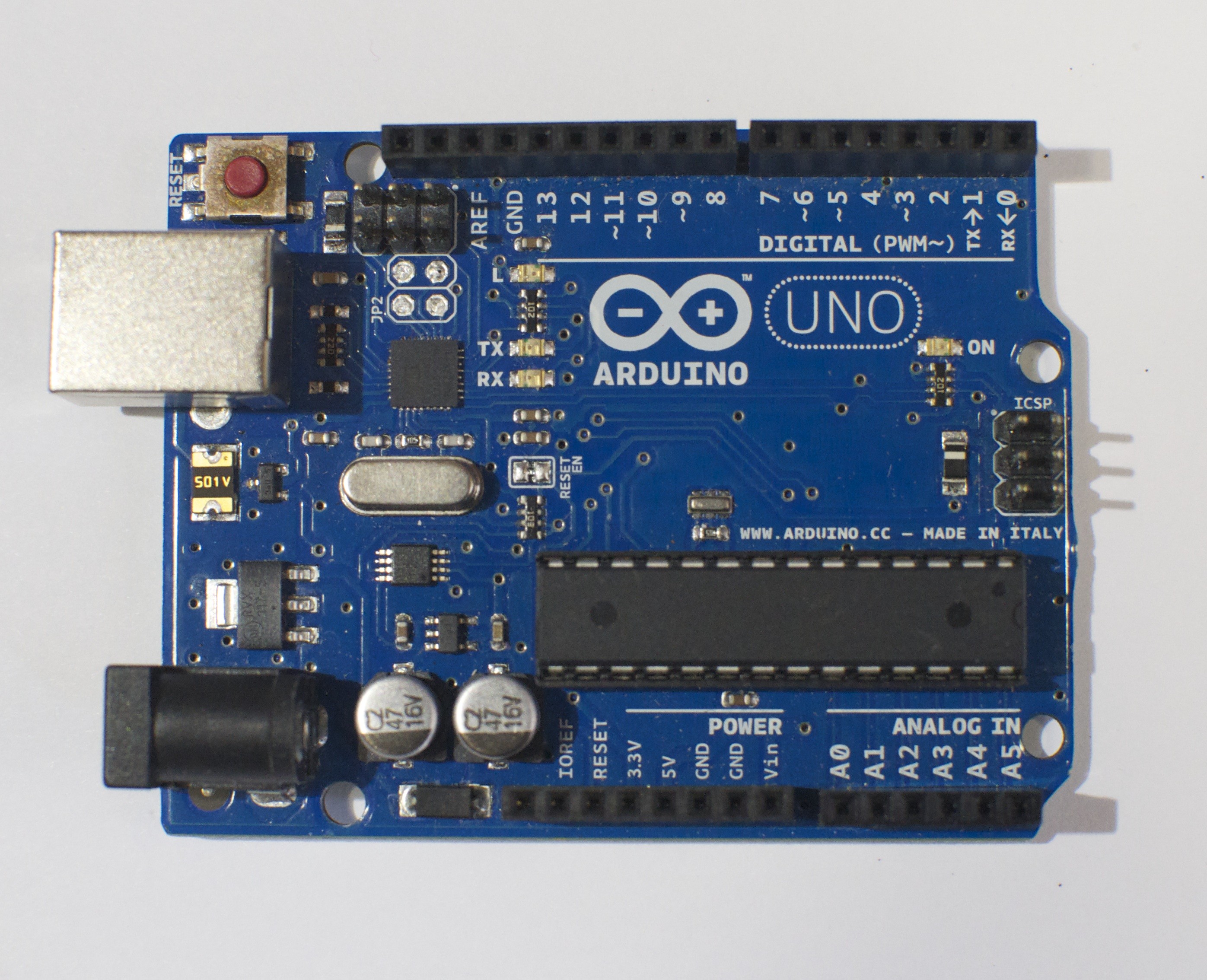
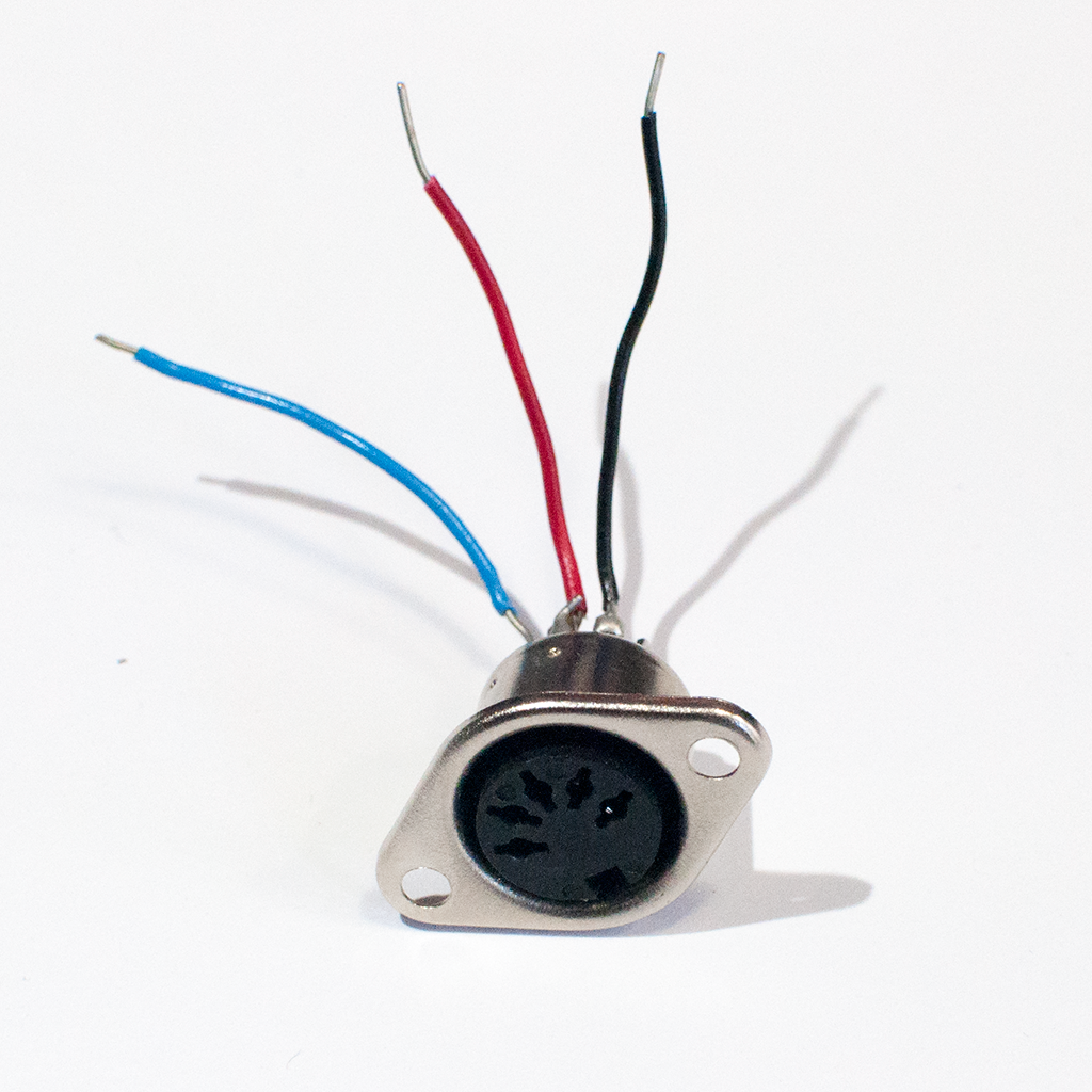
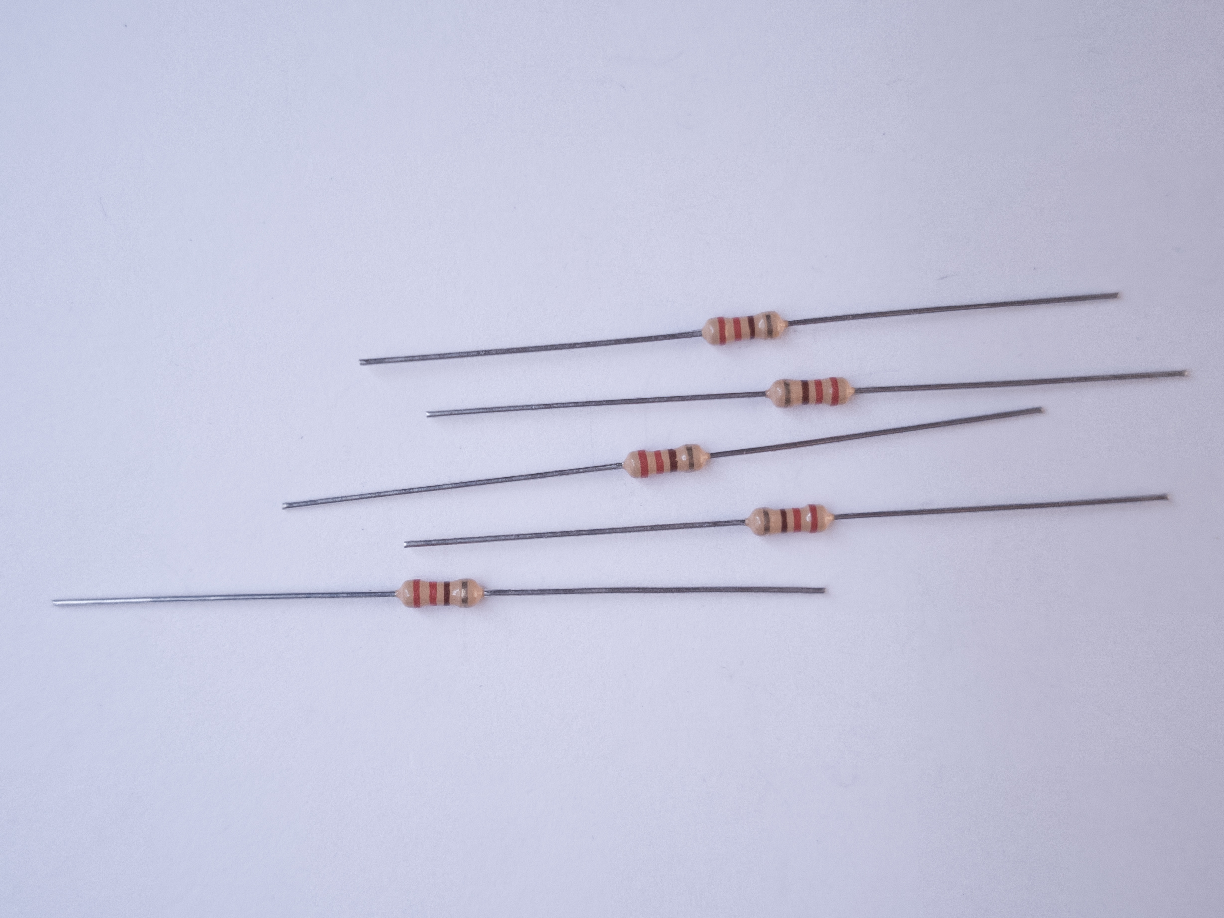
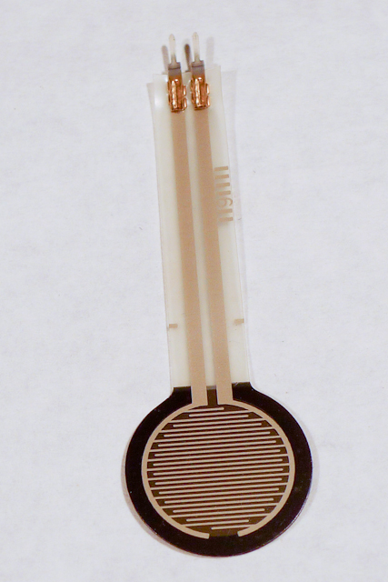
There are three approaches you can take to MIDI output, depending on the board you’re using and the application you have in mind.
If you’re communicating with a MIDI sound module like a synthesizer or sampler, you’ll need to use either Serial or SoftwareSerial output. On the Uno, SoftwareSerial is best. On most other Arduino models, there is a second hardware serial port, Serial1, that you can use for MIDI output.
If you’re communicating with a MIDI program like Ableton, GarageBand, or a soundFont synth like Sforzando, either on a laptop or mobile device, then MIDIUSB is the way to go. The Uno can’t communicate using MIDIUSB, but the Nano 33 IoT, the MKR series, the Leonardo, Micro, or Due can.
If you’re using an Uno or any board with only one serial port, the SoftwareSerial library is your best bet. This section describes how to wire and program your board for SoftwareSerial.
Connect power and ground on the breadboard to power and ground from the microcontroller. On the Arduino module, use the 5V and any of the ground connections (Figure 10):
Made with Fritzing
For the Nano 33 IoT version or any of the MIDIUSB versions (see below), you won’t need a MIDI jack.
Connect an analog sensor to analog pins 0 like you did in the analog lab (Figure 11). Connect a switch to digital pin 10 like you did in the digital lab (Figure 12).
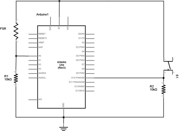
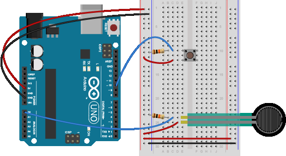
Add the MIDI out jack and a 220-ohm resistor to digital pin 3, as shown in Figure 13-14:
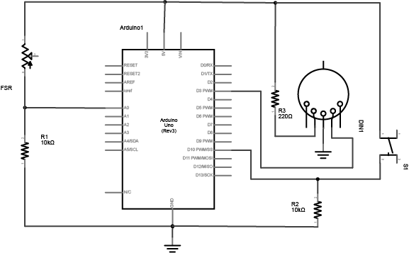
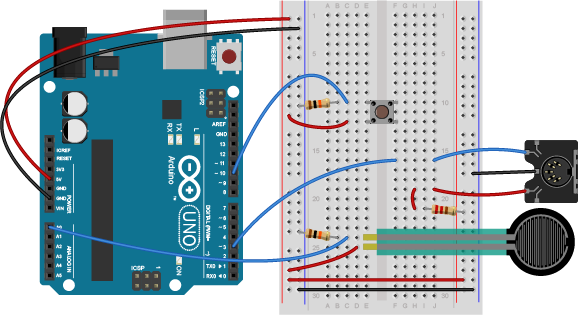
This circuit doesn’t actually match the MIDI specification, but it works with all the MIDI devices we’ve tried it with. This circuit includes an analog and a digital sensor to allow for physical interactivity, but those aren’t necessary to send MIDI data.
Once you’re connected, sending MIDI is just a matter of sending the appropriate bytes. In the code below, you’ll use the SoftwareSerial library to send data on digital pin 3, so that you can keep the hardware serial available for debugging purposes.
The bytes have to be sent as binary values, but you can format them in your code as decimal or hexadecimal values. The example below uses hexadecimal format for any fixed values, and a variable for changing values. All values are sent serially as raw binary values, using the BYTE modifier to .print() (Many MIDI tables give the command values in hex, so this was done in hex for the sake of convenience):
#include"SoftwareSerial.h"

 // Variables:
  byte note = 0;            // The MIDI note value to be played

 //software serial
 SoftwareSerial midiSerial(2, 3); // digital pins that we'll use for soft serial RX and TX

  void setup() {
    //  Set MIDI baud rate:
    Serial.begin(9600);
    midiSerial.begin(31250);
  }

  void loop() {
    // play notes from F#-0 (30) to F#-5 (90):
    for (note = 30; note < 90; note ++) {
      //Note on channel 1 (0x90), some note value (note), middle velocity (0x45):
      noteOn(0x90, note, 0x45);
      delay(100);
      //Note on channel 1 (0x90), some note value (note), silent velocity (0x00):
      noteOn(0x90, note, 0x00);
      delay(100);
    }
  }

  //  plays a MIDI note.  Doesn't check to see that
  //  cmd is greater than 127, or that data values are  less than 127:
  void noteOn(byte cmd, byte data1, byte data2) {
    midiSerial.write(cmd);
    midiSerial.write(data1);
    midiSerial.write(data2);

     //prints the values in the serial monitor so we can see what note we're playing
    Serial.print("cmd: ");
    Serial.print(cmd);
    Serial.print(", data1: ");
    Serial.print(data1);
    Serial.print(", data2: ");
    Serial.println(data2);
  }
There are two alternatives to SoftwareSerial, but they are only available on boards other than the Uno. You could use the second hardware serial port if you have one. Or, if you’re using one of the MKR series boards or a Nano 33 IoT or an M0-based derivative board, you can use MIDIUSB.
If you’re using any board that has two hardware serial ports, you don’t have to use SoftwareSerial. That includes almost any of the official Arduino boards except the Uno: the Nano 33 IoT, the Due, the Mega, the MKR series, the Leonardo, the Micro and the 101 all have two hardware serial ports. You could also use any M0- or 32U4-based derivative board like Adafruit’s Feather and Trinket boards. If you are using one of those boards, copy the circuits above but move the MIDI connector’s pin 4 to the TX1 pin of your board. Then change your code as follows. First, remove the first line that includes the SoftwareSerial library. Then remove the line that initializes SoftwareSerial. Then change midiSerial.begin() to Serial1.begin(). Then change all midiSerial calls to Serial1 calls. Here’s the changed code:
// Variables:
byte note = 0; // The MIDI note value to be played

void setup() {
  // Set MIDI baud rate:
  Serial.begin(9600);
  Serial1.begin(31250);
}

void loop() {
  // play notes from F#-0 (30) to F#-5 (90):
  for (note = 30; note < 90; note ++) {
    // Note on channel 1 (0x90), some note value (note), middle velocity (0x45):
    noteOn(0x90, note, 0x45);
    delay(100);
    // Note on channel 1 (0x90), some note value (note), silent velocity (0x00):
    noteOn(0x90, note, 0x00);
    delay(100);
  }
}

// plays a MIDI note. Doesn't check to see that
// cmd is greater than 127, or that data values are less than 127:
void noteOn(byte cmd, byte data1, byte data2) {
  Serial1.write(cmd);
  Serial1.write(data1);
  Serial1.write(data2);

  //prints the values in the serial monitor so we can see what note we're playing
  Serial.print("cmd: ");
  Serial.print(cmd);
  Serial.print(", data1: ");
  Serial.print(data1);
  Serial.print(", data2: ");
  Serial.println(data2);
}
If you’re using an ARM board like the MKR series, the Nano 33 IoT, the Due, or any of the M0-based derivatives, you can also use MIDIUSB. When you do this, your microcontroller shows up to your computer like a USB MIDI device. This is handy for when you’re connecting to a laptop. It’s less handy for connecting to dedicated synthesizers or samplers.
To do this, dispose of the MIDI socket. You’ll be connecting through your USB connector, and yes, the serial connection to the Serial Monitor will still work as well. Change your code as follows. First include the MIDIUSB library (you might need to install it using the Library Manager) at the top of your code. Then remove the Serial1.begin() line in the setup. Then replace the Serial1.write() lines in the noteOn function with the MIDI code shown below:
  #include "MIDIUSB.h"
  // Variables:
  byte note = 0;            // The MIDI note value to be played

  void setup() {
    Serial.begin(9600);
  }

  void loop() {
    // play notes from F#-0 (30) to F#-5 (90):
    for (note = 30; note < 90; note ++) {
      //Note on channel 1 (0x90), some note value (note), middle velocity (0x45):
      noteOn(0x90, note, 0x45); delay(100);
      //Note on channel 1 (0x90), some note value (note), silent velocity (0x00):
      noteOn(0x90, note, 0x00); delay(100);
     }
   }

   // plays a MIDI note. Doesn't check to see that
   // cmd is greater than 127, or that data values are less than 127:
   void noteOn(byte cmd, byte data1, byte data2) {
     /* First parameter is the event type (top 4 bits of the command byte).
        Second parameter is command byte combined with the channel.
        Third parameter is the first data byte
        Fourth parameter second data byte, if there is one:
    */
    midiEventPacket_t midiMsg = {cmd >> 4, cmd, data1, data2};
    MidiUSB.sendMIDI(midiMsg);

    //prints the values in the serial monitor so we can see what note we're playing
    Serial.print("cmd: ");
    Serial.print(cmd);
    Serial.print(", data1: ");
    Serial.print(data1);
    Serial.print(", data2: ");
    Serial.println(data2);
  }
The MIDIUSB library on the SAMD boards (MKRZero, MKR1xxx, Nano 33IoT) has an unusual behavior: using it changes the serial port enumeration. When you include the MIDIUSB library in a sketch, your board’s serial port number will change. For example, on MacOS, if the port number is /dev/cu.usbmodem14101, then adding the MIDIUSB library will change it to /dev/cu.usbmodem14102. Removing the MIDIUSB library will change it back to /dev/cu.usbmodem14101. Similarly, if you double-tap the reset button to put the board in bootloader mode, the serial port will re-enumerate to its original number.
You may have trouble getting these MIDI sketches to work on Windows. On Windows, the default Arduino drivers must be uninstalled so the system can recognize the Arduino as both serial device and MIDI device. Read this issue and follow the instructions there.
The previous example will just play notes, no interactivity. The example below uses an analog input to set the pitch, and a digital input (a switch) to start and stop the note:
 #include "SoftwareSerial.h"

 const int switchPin = 10;  // The switch is on Arduino pin 10
 const int LEDpin = 13;     //  Indicator LED

  // Variables:
  byte note = 0;              // The MIDI note value to be played
  int AnalogValue = 0;        // value from the analog input
  int lastNotePlayed = 0;     // note turned on when you press the switch
  int lastSwitchState = 0;    // state of the switch during previous time through the main loop
  int currentSwitchState = 0;

 //software serial
 SoftwareSerial midiSerial(2, 3); // digital pins that we'll use for soft serial RX and TX

  void setup() {
    //  set the states of the I/O pins:
    pinMode(switchPin, INPUT);
    pinMode(LEDpin, OUTPUT);
    //  Set MIDI baud rate:
    Serial.begin(9600);
    midiSerial.begin(31250);
  }

  void loop() {
    //  My potentiometer gave a range from 0 to 1023:
    AnalogValue = analogRead(0);
    //  convert to a range from 0 to 127:
    note = AnalogValue/8;
    currentSwitchState = digitalRead(switchPin);
    // Check to see that the switch is pressed:
    if (currentSwitchState == 1) {
      //  check to see that the switch wasn't pressed last time
      //  through the main loop:
      if (lastSwitchState == 0) {
        // set the note value based on the analog value, plus a couple octaves:
        // note = note + 60;
        // start a note playing:
        noteOn(0x90, note, 0x40);
        // save the note we played, so we can turn it off:
        lastNotePlayed = note;
        digitalWrite(LEDpin, HIGH);
      }
    }
    else {   // if the switch is not pressed:
      //  but the switch was pressed last time through the main loop:
      if (lastSwitchState == 1) {
        //  stop the last note played:
        noteOn(0x90, lastNotePlayed, 0x00);
        digitalWrite(LEDpin, LOW);
      }
    }

    //  save the state of the switch for next time
    //  through the main loop:
    lastSwitchState = currentSwitchState;
  }

  //  plays a MIDI note.  Doesn't check to see that
  //  cmd is greater than 127, or that data values are  less than 127:
  void noteOn(byte cmd, byte data1, byte  data2) {
    midiSerial.write(cmd);
    midiSerial.write(data1);
    midiSerial.write(data2);

   //prints the values in the serial monitor so we can see what note we're playing
    Serial.print("cmd: ");
    Serial.print(cmd);
    Serial.print(", data1: ");
    Serial.print(data1);
    Serial.print(", data2: ");
    Serial.println(data2);
  }
Now that you’ve got the basics, make a musical instrument. Consider a few things in designing your instrument:
All of these questions, and many more, will affect what sensors you use, how you read them, and how you design both the physical interface and the software.
For more on MIDI, music, and instruments, see these notes, and this overview of MIDI on the Arduino.