In this lab, you’ll send data using asynchronous serial communication from a single sensor to a Processing sketch on a personal computer that will then graph the sensor’s value onscreen.
In this lab, you’ll send data using asynchronous serial communication from a single sensor to a Processing sketch on a personal computer that will then graph the sensor’s value onscreen.
Introduction
Asynchronous serial communication, which you’ll see demonstrated in this lab, is one of the most common means of communication between a microcontroller and another computer. You’ll use it in nearly every project, for debugging purposes if nothing else.
The Processing sketch in this exercise graphs the incoming bytes. Graphing a sensor’s value like this is a useful way to get a sense of its behavior.
Figure 1-3 are basically what you need for this lab.
Figure 1: Arduino Nano 33 IoT
Figure 2: 22AWG hookup wire
Figure 3: Potentiometer
Connect the sensor
Connect your analog sensor to analog pin 0 like you did in the analog lab. A potentiometer is shown here (Figure 4-6) because it’s easy, but you might want to pick a sensor that’s more interesting. IR distance rangers are fun for this exercise, for example. Force-sensing resistors are good as well.
Figure 4: Schematic view of a potentiometer connected to analog in 0 of the Arduino
Figure 5: Breadboard view of a potentiometer connected to analog in 0 of an Arduino
Figure 6: Breadboard view of an Arduino Nano connected to analog in 0 of the nano (physical pin 4).
Read the Sensor Value and Send the Data Serially
Program the Arduino module to read the analog sensor and print the results to the Serial monitor. To do this, you’ll use the Arduino serial commands. You’ve been using these in the digital and analog labs to send data to the Serial Monitor. Instead of using the Serial.println() command as you did in those labs, however, use Serial.write(). This will send the sensor value as a raw binary value rather than as a string:
void setup() {
  Serial.begin(9600);
}

void loop() {
  int analogValue = analogRead(A0)/4; // read the sensor value
  Serial.write(analogValue);          // send the value serially as a binary value
}
Note: Why divide the sensor value by 4?
Dividing the sensor value by 4 reduces the range to 0 to 255, the range that can fit in a single byte.
When you open the Serial Monitor, you will see garbage characters(Figure 7). What’s going on? The Serial.write() command doesn’t format the bytes as ASCII characters. It sends out the binary value of the sensor reading. Each sensor reading can range from 0 to 1023; in other words, it has a 10-bit range, since 210 = 1024 possible values. Since that’s more than the eight bits that can fit in a byte, you’re dividing the value by 4 in the code above, to get a range from 0 to 255, or 28 bits. For more background on this, see the notes on variables.
Figure 7: The Arduino IDE with the serial monitor open. The serial monitor screen is showing arbitrary characters. What is happening?
So, for example, if the sensor reading’s value is 234, then the Serial.write() command sends the binary value 11101010. If the reading is 255, then Serial.write() sends 11111111. If it’s 157, then the command sends 10011101. For more decimal-to-binary conversions, open your computer’s calculator and choose the Programmer view (press apple-3 on a mac, and Alt-3 on Windows).
When the Serial Monitor receives a byte, it and assumes it should show you the ASCII character corresponding to that byte’s value. The garbage characters are characters corresponding to the ASCII values the Monitor is receiving. You’ll learn more about that in the two-way serial lab.
Sending data using Serial.write() is efficient for the computer, but it’s difficult to read. However, there are other ways to see the serial data. The serial terminal program CoolTerm is available for Mac, Windows, and Linux. It gives you both an ASCII view of incoming bytes and a hexadecimal view (Figure 8). Download it and install it, and open the Options tab. From there, pick your serial port in the menu, then close the Options tab. Then click the Connect button to open the serial port. Related Video: Using CoolTerm
Figure 8: The CoolTerm serial terminal application showing the hexadecimal view.
NOTE: only one program can control a serial port at a time. When you’re not using a given program, remember to close the serial port. You won’t be able to re-program the Arduino module if you don’t, because the serial terminal program will have control of the serial port.
Once you have data coming into CoolTerm, click the Hex button. Instead of seeing the ASCII representation of the byte, you’ll see its hexadecimal value, with the ASCII characters down the side. As you change the sensor’s value, you’ll see the values change.
Remember, the microcontroller is just sending a series of electrical pulses. How those pulses are interpreted is up to the program that reads them. In CoolTerm, you see two different interpretations, the hexadecimal value and the ASCII character corresponding to the value.
For most projects, you’ll set the port settings to 9600 bits per second, 8 data bits, no parity, one stop bit, and no hardware flow control. This will be set in the Preferences or Settings or Connection Options of whatever program you’re using. Once you’ve applied those settings, open the serial port by clicking. Any bytes you type in the window will be sent out the serial port you opened. They won’t show up on the screen, however. Any bytes received in the serial port will be displayed in the window. Click the Disconnect button to close the serial port.
The serial monitor in Arduino and CoolTerm aren’t the only programs on your computer that can read data in from the microcontroller. Any program that can access the computer’s serial ports can do it. Processing is an excellent tool for reading serial data because you can program it to interpret the data any way you want. Write a program to take in serial bytes and graph them.
The first thing you need to do is to import the Processing Serial Library. This is a code library that adds functionality to Processing so it can read from and write to the computer’s serial ports. You can do this by choosing the Sketch menu, then Import Library...-->serial, or you can type:
Processing code:
import processing.serial.*;
To use the serial library, create an instance of the library in a global variable as shown below:
Processing code:
Serial myPort;
Note: you might get an error message when trying to use the Processing Serial Library for the first time. Here are instructions on what to do if this happens.
In the setup() method, set the window size, and use the serial library to get a list of the serial ports:
Processing code:
void setup () {
size(800, 600); // window size
// List all the available serial ports
println(Serial.list());
}
If you run what you’ve typed so far, you should get a list of the serial ports in the monitor pane that looks a bit like this on a mac. On a Windows machine, the port list will have names like COM3, COM4, COM5, and so forth:
One of these ports is the same as the serial port name you use in the Arduino programming environment. That’s the one you want. In this case, it’s /dev/tty.usbmodem1421 or the 13th item in the list. But since arrays start counting at zero, that item is counted as the 12th item. So to open that port, add the following lines at the end of the setup:
Processing code:
// change the number below to match your port:
String portName = Serial.list()[12];
myPort = new Serial(this, portName, 9600);
Finally, set the background color. Pick a nice color, don’t just use primary colors. You’ll be looking at it a long time, so you might as well like it. If you can’t think of a nice color combination, try color.adobe.com. Add this to the end of the setup:
Processing code:
background(#081640);
The serial library has a special method called serialEvent(). Every time a new byte arrives in the serial port, serialEvent() is called. So you can use it to read bytes coming in the serial port from the microcontroller. Write a serialEvent method that reads the incoming byte and prints it out:
Processing code:
void serialEvent (Serial myPort) {
// get the byte:
int inByte = myPort.read();
// print it:
println(inByte);
}
myPort.read() tells the program to read a byte from the serial port myPort. Bytes are read like peas coming out of a peashooter. Every time you read a byte, it’s removed from the serial buffer. So it’s good practice to read the byte into a variable as shown above, then never read again until you want another byte. If you want to do something with the byte you read (like graphing it), use the variable in which you saved the incoming byte.
Graph the Sensor Value
Now it’s time to draw a graph with the bytes you read. To do this, you’ll pick a point whose distance from the bottom of the window corresponds to the byte’s value. In other words, the vertical position (call it yPos) equals the height minus the byte’s value (yPos = height - inByte). Add global variables called xPos and yPos and set them to 0. Then in the draw(), set the stroke color to a nice color, and draw a line at xPos, from the bottom of the screen to the vertical position you just calculated.
Add this at the top of the program:
Processing code:
// at the top of the program:
float xPos = 0; // horizontal position of the graph
float yPos = 0; // vertical position of the graph
Add this to the end of the serialEvent() method. it will change yPos based on the last byte you read from the serial port:
yPos = height – inByte;
Then add this draw() method:
Processing code:
void draw () {
// draw the line in a pretty color:
stroke(#A8D9A7);
line(xPos, height, xPos, yPos);
}
Finally you need to increment the horizontal position after you draw the line, so that the next byte’s line is further along on the graph. If you reach the edge of the screen, set the horizontal position back to 0. Do this at the end of the draw():
Processing code:
// at the edge of the screen, go back to the beginning:
if (xPos >= width) {
xPos = 0;
// clear the screen by resetting the background:
background(#081640);
} else {
// increment the horizontal position for the next reading:
xPos++;
}
That’s it! When you run this sketch, you’ll see the sensor’s value graphed on the screen like so (Figure 9):
Figure 9: Graphing a sensor in Processing. The sensor’s value is represented by rising and falling green lines which create a graph.
In this tutorial, you’ll learn how to control a servomotor’s position from a microcontroller using the value returned from an analog sensor.
In this tutorial, you’ll learn how to control a servomotor’s position from a microcontroller using the value returned from an analog sensor.
Introduction
Servos are the easiest way to start making motion with a microcontroller. Servos can turn through a range of 180 degrees and you can use them to create all sorts of periodic or reciprocating motions. Check out some of the mechanisms at Rob Ive’s site for ideas on how to make levers, cams, and other simple machines for making motion. The resources section of this site has links to other sites on construction, mechanics, and kinetics as well.
What You’ll Need to Know
To get the most out of this lab, you should be familiar with the following concepts. You can check how to do so in the links below:
Flexible jumper wires. These wires are quick for breadboard prototyping, but can get messy when you have lots of them on a board.
A solderless breadboard with two rows of holes along each side. The . board is turned sideways so that the side rows are on top and bottom in this view. There are no components mounted on the board.
Potentiometer
10-kilohm resistors. These ones are 5-band resistors
RC Servomotor
Force Sensing Resistor (FSR)
Phototransistors. The short leg goes to voltage, and the long leg goes to the input pin of a microcontroller.
Figures 1-8. The parts you’ll need for this exercise. Click on any image for a larger view.
Prepare the breadboard
Connect power and ground on the breadboard to power and ground from the microcontroller. On the Arduino module, use the 5V or 3.3V (depending on your model) and any of the ground connections, as shown in Figures 9 and 10.
Figure 9 Breadboard view of an Arduino Uno on the left connected to a solderless breadboard, right.
Figure 9. An Arduino Uno on the left connected to a solderless breadboard, right. The Uno’s 5V output hole is connected to the red column of holes on the far left side of the breadboard. The Uno’s ground hole is connected to the blue column on the left of the board. The red and blue columns on the left of the breadboard are connected to the red and blue columns on the right side of the breadboard with red and black wires, respectively. These columns on the side of a breadboard are commonly called the buses. The red line is the voltage bus, and the black or blue line is the ground bus.
Figure 10. An Arduino Nano mounted on a solderless breadboard. The Nano is mounted at the top of the breadboard, straddling the center divide, with its USB connector facing up. The top pins of the Nano are in row 1 of the breadboard.
The Nano, like all Dual-Inline Package (DIP) modules, has its physical pins numbered in a U shape, from top left to bottom left, to bottom right to top right. The Nano’s 3.3V pin (physical pin 2) is connected to the left side red column of the breadboard. The Nano’s GND pin (physical pin 14) is connected to the left side black column. These columns on the side of a breadboard are commonly called the buses. The red line is the voltage bus, and the black or blue line is the ground bus. The blue columns (ground buses) are connected together at the bottom of the breadboard with a black wire. The red columns (voltage buses) are connected together at the bottom of the breadboard with a red wire.
Connect an analog input to analog pin 0 as you did in the Analog Input Lab covered previously. A force-sensing resistor is shown in Figure 11-14 below, but you can also use a potentiometer, phototransistor, or any analog input you prefer. Then connect an RC servomotor to digital pin 9. The yellow wire of the servo goes to the pin, and the red and black wires go to +5V and ground, respectively.
Most RC servomotors are rated for 4-6 volt power input. When you’re using a 3.3V microcontroller like the Nano 33 IoT, you can use the Vin pin to power the motor if you’re running off USB power, or off a 5V source connected to the Vin.
Safety Warning! Not all servos have the same wiring colors. For example, the Hextronik servos that come with Adafruit’s ARDX kit use red for +5V, brown for ground, and mustard yellow for control. Check the specifications on your particular servomotor to be sure.
Figure 11. Schematic view of a servomotor and an analog input attached to an Arduino Uno.
Figure 12. Breadboard view of a servomotor and an analog input attached to an Arduino Uno.
Figure 13. Schematic view of a servomotor and an analog input attached to an Arduino Nano 33 IoT.Figure 14. Breadboard view of a servomotor and an analog input attached to an Arduino Nano 33 IoT.
When you attach the servo, you’ll need a row of three male headers to attach it to a breadboard. You may find that the pins don’t stay in the servo’s connector holes. Put the pins in the servo’s connector, then push them down on a table gently. They will slide up inside their plastic sheaths, and fit better in your servo’s connector.
Different RC servomotors will have different current requirements. The Tower SG5010 model servo sold by Adafruit draws more current than the HiTec HS311 and HS318 sold by ServoCity, for example. The Tower Pro servo draws 100-300 mA with no load attached, while the HiTec servos draw 160-180mA. The decoupling capacitor in the circuit will smooth out any voltage dips that occur when the servo turns on, but you will need an external 5V supply if you are using more than one servomotor.
Figure 15. Attaching header pins to a servomotor connector. If your header pins are too short, as shown here, you can lengthen them.
Figure 16. Push the short ends of the header pins into the servomotor connector’s holes and then brace the long ends against a tabletop while you push down on the connector. Do this gently and the header pins will move in their plastic mount.
Figure 17. Now your header pins will be longer on top and shorter on bottom, and will stay firmly in the servomotor connector.
Program the Microcontroller
First, find out the range of your sensor by using analogRead() to read the sensor and printing out the results.
void setup() {
  Serial.begin(9600);       // initialize serial communications
}

void loop()
{
  int analogValue = analogRead(A0); // read the analog input
  Serial.println(analogValue);      // print it
}
Now, map the result of the analog reading to a range from 0 to 179, which is the range of the sensor in degrees. Store the mapped value in a local variable called servoAngle.
void setup() {
  Serial.begin(9600);       // initialize serial communications
}

void loop()
{
  int analogValue = analogRead(A0); // read the analog input
  Serial.println(analogValue);      // print it

  // if your sensor's range is less than 0 to 1023, you'll need to
  // modify the map() function to use the values you discovered:
  int servoAngle = map(analogValue, 0, 1023, 0, 179);
}
Finally, add the servo library at the beginning of your code, then make a variable to hold an instance of the library, and a variable for the servo’s output pin. In the setup(), initialize your servo using servo.attach(). Then in your main loop, use servoAngle to set the servo’s position.
#include "Servo.h"      // include the servo library

Servo servoMotor;       // creates an instance of the servo object to control a servo
int servoPin = 9;       // Control pin for servo motor
// time when the servo was last updated, in ms
long lastMoveTime = 0;

void setup() {
  Serial.begin(9600);       // initialize serial communications
  servoMotor.attach(servoPin);  // attaches the servo on pin 9 to the servo object
}

void loop() {
  int analogValue = analogRead(A0); // read the analog input
  Serial.println(analogValue);      // print it

  // if your sensor's range is less than 0 to 1023, you'll need to
  // modify the map() function to use the values you discovered:
  int servoAngle = map(analogValue, 0, 1023, 0, 179);

  // move the servo using the angle from the sensor every 20 ms:
  if (millis() - lastMoveTime > 20) {
    servoMotor.write(servoAngle);
    lastMoveTime = millis();
  }
}
Servo motors give you the power to do all kinds of things.
They can be used to push a remote control button, in a pinch, as shown in Figure 18.
Figure 18. A servomotor can press remote control buttons The remote control is mounted in a wooden frame, and the servo is mounted on the side of the frame. The servo horn moves down to press the power button.
You can play music with found objects like in this Project by Nick Yulman. You can build a frisking machine like in this project by Sam Lavigne and Fletcher Bach. If you’ve got 800 or so of them and a lot of time, you can build a wooden mirror like this Project by Daniel Rozin.
In this lab, you’ll learn how to connect a variable resistor to a microcontroller and read it as an analog input. You’ll be able to read changing conditions from the physical world and convert them to changing variables in a program.
Introduction
In this lab, you’ll learn how to connect a variable resistor to a microcontroller and read it as an analog input. You’ll be able to read changing conditions from the physical world and convert them to changing variables in a program.
Many of the most useful sensors you might connect to a microcontroller are analog input sensors. They deliver a variable voltage, which you read on the analog input pins using the analogRead() command.
To get the most out of this lab, you should be familiar with the following concepts and you should install the Arduino IDE on your computer. You can check how to do so in the links below:
Arduino Nano 33 IoTFlexible jumper wires. These wires are quick for breadboard prototyping, but can get messy when you have lots of them on a board.A solderless breadboard with two rows of holes along each side. The . board is turned sideways so that the side rows are on top and bottom in this view. There are no components mounted on the board. Photo of an 8 ohm speakerLEDs. The long leg goes to voltage and the short leg goes to ground220-ohm resistors. These ones are 4-band resistors10-kilohm resistors. These ones are 5-band resistorsPushbuttonsPotentiometerForce Sensing Resistor (FSR)ThermistorPhototransistors. The short leg goes to voltage, and the long leg goes to the input pin of a microcontroller.Figure 1-12. The parts you’ll need for this exercise. Click on any image for a larger view.
Figures 1-12 show the parts you’ll need for this exercise. Click on any image for a larger view.
Set Up the Breadboard
Connect power and ground on the breadboard to power and ground from the microcontroller. On the Arduino module, use the 5V or 3.3V (depending on your model) and any of the ground connections. Figures 13 and 14 show how to do this for an Arduino Uno and an Arduino Nano 33 IoT.
As shown in Figure 13, the Uno’s 5V output hole is connected to the red column of holes on the far left side of the breadboard. The Uno’s ground hole is connected to the blue column on the left of the board. The red and blue columns on the left of the breadboard are connected to the red and blue columns on the right side of the breadboard with red and black wires, respectively. These columns on the side of a breadboard are commonly called the buses. The red line is the voltage bus, and the black or blue line is the ground bus.
Figure 13. An Arduino Uno on the left connected to a solderless breadboard, right.
Figure 14. Breadboard view of an Arduino Nano mounted on a breadboard
In Figure 14, the Nano is mounted at the top of the breadboard, straddling the center divide, with its USB connector facing up. The top pins of the Nano are in row 1 of the breadboard.
The Nano, like all Dual-Inline Package (DIP) modules, has its physical pins numbered in a U shape, from top left to bottom left, to bottom right to top right. The Nano’s 3.3V pin (physical pin 2) is connected to the left side red column of the breadboard. The Nano’s GND pin (physical pin 14) is connected to the left side black column. These columns on the side of a breadboard are commonly called the buses. The red line is the voltage bus, and the black or blue line is the ground bus. The blue columns (ground buses) are connected together at the bottom of the breadboard with a black wire. The red columns (voltage buses) are connected together at the bottom of the breadboard with a red wire.
Add a Potentiometer and LED
Connect the wiper of a potentiometer to analog in pin 0 of the module and its outer connections to voltage and ground. Connect a 220-ohm resistor to digital pin 9. You can replace the LED with a speaker if you prefer audible output. Connect the anode of an LED to the other side of the resistor, and the cathode to ground as shown below. See Figure 15 and Figure 16 to learn how to do this with an Arduino Uno. Figure 17 shows a breadboard view of an Arduino Nano for the same circuit.
Figure 15. Schematic view of a potentiometer connected to analog in 0 of an Arduino and an LED connected to digital pin 9. Connect the voltage lead of the potentiometer to 5V for Uno, 3.3V for Nano 33 IoT.
Figure 16. Breadboard view of a potentiometer connected to analog in 0 of an Arduino and an LED connected to digital pin 9.
Figure 17. Breadboard view of Arduino Nano with an analog input and LED output.
Figure 17 shows the breadboard view of an Arduino Nano connected to a potentiometer and an LED. The +3.3 volts and ground pins of the Arduino are connected by red and black wires, respectively, to the left side rows of the breadboard. +3.3 volts is connected to the left outer side row (the voltage bus) and ground is connected to the left inner side row (the ground bus). The side rows on the left are connected to the side rows on the right using red and black wires, respectively, creating a voltage bus and a ground bus on both sides of the board. The potentiometer is mounted in the left center section of the solderless breadboard. Its outside pins are connected to the voltage and ground buses, respectively There is a wire connecting to analog in 0 of the nano (physical pin 4) to the the center pin of the potentiometer. An LED is mounted in the right center section of the board, with a 220-ohm resistor attached to its anode (long leg). The other end of the resistor connects to the Nano’s digital pin 9 (physical pin 27). The cathode of the LED (short leg) connects to ground. If you’re using a speaker instead of the LED, connect it to the same connections as the LED.
Program the Module
Now that you have the board wired correctly, program your Arduino as follows:
First, establish some global variables: one to hold the value returned by the potentiometer, and another to hold the brightness value. Make a global constant to give the LED’s pin number a name.
const int ledPin = 9;       // pin that the LED is attached to
int analogValue = 0;        // value read from the pot
int brightness = 0;         // PWM pin that the LED is on.
In the setup() method, initialize serial communications at 9600 bits per second, and set the LED’s pin to be an output.
  // initialize serial communications at 9600 bps:
    Serial.begin(9600);
    // declare the led pin as an output:
    pinMode(ledPin, OUTPUT);
}
In the main loop, read the analog value using analogRead() and put the result into the variable that holds the analog value. Then divide the analog value by 4 to get it into a range from 0 to 255. Then use the analogWrite() command to face the LED. Then print out the brightness value. An alternate loop function for the speaker follows right after the first one.
void loop() {
    analogValue = analogRead(A0);    // read the pot value
    brightness = analogValue /4;       //divide by 4 to fit in a byte
    analogWrite(ledPin, brightness);   // PWM the LED with the brightness value
    Serial.println(brightness);        // print the brightness value back to the serial monitor
}
If you’re replacing the LED with a speaker, here’s an alternate loop function that will play a changing tone on the speaker:
void loop() {
    analogValue = analogRead(A0);      // read the pot value
    frequency = (analogValue /4) * 10; // divide by 4 to fit in a byte, multiply by 10 for a good tonal range
    tone(pinNumber, frequency);        // make a changing tone on the speaker
    Serial.println(brightness);        // print the brightness value back to the serial monitor
}
When you run this code, the LED should dim up and down as you turn the pot, and the brightness value should show up in the serial monitor.
Other variable resistors
You can use many different types of variable resistors for analog input. For example, the pink monkey in the photo below has his arms wired with flex sensors. These sensors change their resistance as they are flexed. When the monkey’s arms move up and down, the values of the flex sensors change the brightness of two LEDs. The same values could be used to control servo motors, change the frequency on a speaker, or move servo motors.
Figure 18. A stuffed pink monkey with flex sensors attached
Note on Soldering Sensor Leads
Flex sensors and force-sensing resistors melt easily, so unless you are very quick with a soldering iron, it’s risky to solder directly to their leads. See Figure 19-21 to learn about three better solutions:
Figure 19. Wire-wrapped connections of a force-sensing resistor
Figure 20. Screw terminal connection for force sensing resistor
Figure 21. Force sensing resistor connected to breakaway socket headers
If you’d like to read a changing light level, you can use a phototransistor for the job. Phototransistors are not variable resistors like photoresistors (which are shown in this video), but they perform similarly are made from less toxic materials. They are actually transistors in which the light falling on the sensor acts as the transistor’s base. Like photoresistors, they are sensitive to changes in light, and they work well in the same voltage divider circuit. Figure 22 shows how to connect a phototransistor and a 10-kilohm resistor as an analog input:
Figure 22. Breadboard view of an Arduino Nano connected to a phototransistor as an analog input. The long leg of the phototransistor connects to voltage, and the long leg connects to the input pin. The 10-kilohm fixed resistor then connects from the input pin to ground.
Different phototransistors will have different sensitivities to light. For example, this model from Everlight, which has a clear top, is most sensitive to 390 – 700 nm light range, with a peak at 630nm (orange-red). This model from Excelitas has a colored top to block IR light, and has a range from 450 -700nm, with a peak at 585nm (yellow). For the frequencies of the visible light spectrum, see this chart from Wikipedia.
Figure 23 and 24 shows an example circuit much like the pink monkey circuit (Figure 18) above, but with force-sensing resistors instead of flex sensors.
On the breadboard, two force-sensing resistors are mounted in rows 16 and 17 and 24 and 25, respectively, in the left center section of the board. Two red wires connects rows 16 and 24 in the left center section to the voltage bus on the left side. Two 10-kilohm resistors (orange, black, brown, and gold bands) connect rows 17 and 25 to the ground bus on the left hand side. Two blue wires connect from rows 17 and 25 to analog in pins 0 and 1 of the Arduino, respectively. Two 220-ohm resistors straddle the center divide of the breadboard, connecting to row 7 on both sides and 11 on both sides, respectively. In the left center section of the breadboard, two blue wires connect rows 7 and 11 to pins D10 and D9 of the Arduino, respectively. In the right center section, the anodes of two LEDs are connected to rows 7 and 11, respectively. The cathodes of the LED are in rows 6 and 10, respectively. Two black wire connects row 6 and 10 to the ground bus on the right side of the board.
Figure 23. Schematic view of two force-sensing resistors and two LEDs attached to an Arduino.
Figure 24. Breadboard view of two force-sensing resistors and two LEDs attached to an Arduino.
The circuit above works for any variable resistor. You could replace the force-sensing resistors with flex sensors to use the monkey toy above with this circuit. Two resistors placed in series like this are called a voltage divider. There are two voltage dividers in the circuit shown, one on analog in 0 and one on analog in 1. The fixed resistor in each circuit should have the same order of magnitude as the variable resistor’s range. For example, if you’re using a flex sensor with a range of 50 – 100 kilohms, you might use a 47-kilohm or a 100-kilohm fixed resistor. If you’re using a force sensing resistor that goes from infinity ohms to 10 ohms, but most of its range is between 10 kilohms and 10 ohms, you might use a 10-kilohm fixed resistor.
The code above assumed you were using a potentiometer, which always gives the full range of analog input, which is 0 to 1023. Dividing by 4 gives you a range of 0 to 255, which is the full output range of the analogWrite() command. The voltage divider circuit, on the other hand, can’t give you the full range. The fixed resistor in the circuit limits the range. You’ll need to modify the code or the resistor if you want a different range.
The range of an analog sensor depends on both its electrical properties and its physical setting. Sometimes two sensors of the same type will give a different range, perhaps because they’re mounted differently, or because you’re activating them differently.
For example, the force sensing resistors above will perform differently when you press on them on a hard surface than when you use a soft surface under them. They’ll perform differently again when you pick them up and pinch them. Similarly, light sensors’ performance depends both on your actions and on changes in the ambient light. Two light sensors relatively near each other might have a different range if the light hits them both differently.
As a result, whenever you work with an analog sensor, you should wire it up, mount it physically in a way that you intend it to be used, then write a test program to find its range. Here’s how:
To find out your range, mount your sensor how you intend to use it, then write the simplest analog input program to test the range:
void loop() {
  // read the sensor on analog pin 0:
  int sensorValue = analogRead(A0);
  // print out the value you read:
  Serial.println(sensorValue);
}
Open the serial monitor and watch the printout as you press the FSR or flex the flex sensor. Note the maximum value and the minimum value. Then you can map the range that the sensor actually gives as input to the range that the LED needs as output.
For example, if your photocell gives a range from 400 to 900, you’d do this:
// map the sensor value from the input range (400 - 900, for example) to the output range (0-255):
int brightness = map(sensorValue, 400, 900, 0, 255);
analogWrite(ledPin, brightness);
You can also constrain the values if you find that the range is sometimes going higher or lower than you expected, like so:
// constrain the sensor value in case the raw values go
// below 400 or above 900:
sensorValue = constrain(sensorValue, 400, 900);
// then map the sensor value from the input range (400 - 900, for example) to the output range (0-255):
int brightness = map(sensorValue, 400, 900, 0, 255);
analogWrite(ledPin, brightness);
Here’s another example: you know that the maximum input range of any analog input is from 0 to 5 volts (or 3.3 volts with a Nano 33 IoT). So if you wanted to know the voltage on an analog input pin at any point, you could do some math to extrapolate it in your loop() like so:
void loop() {
  // read the sensor on analog pin 0:
  int sensorValue = analogRead(A0);
  // Convert the analog reading (which goes from 0 - 1023) to a voltage (0 - 5V):
  float voltage = sensorValue * (5.0 / 1023.0);
  // for 0-3.3V use the line below:
  // voltage = sensorValue * (3.3 / 1023.0);
  // print out the value you read:
  Serial.println(voltage);
}
Now write a sketch to control the red LED with the first sensor (we’ll call it the right hand sensor) and the green LED with the second sensor (we’ll call it the left hand sensor). First, make two constants for the LED pin numbers, and two variables for the left and right sensor values.
const int redLED = 10;     // pin that the red LED is on
const int greenLED = 11;   // pin that the green LED is on
int rightSensorValue = 0;  // value read from the right analog sensor
int leftSensorValue = 0;   // value read from the left analog sensor
In the setup(), initialize serial communication at 9600 bits per second, and make the LED pins outputs.
void setup() {
  // initialize serial communications at 9600 bps:
  Serial.begin(9600);
  // declare the led pins as outputs:
  pinMode(redLED, OUTPUT);
  pinMode(greenLED, OUTPUT);
}
Start the main loop by reading the right sensor using analogRead(). Map it to a range from 0 to 255. Then use analogWrite() to set the brightness of the LED from the mapped value. Print the sensor value out as well.
void loop() {
  rightSensorValue = analogRead(A0); // read the pot value
  // constrain the sensor value in case the raw values go
  // below 400 or above 900:
   rightSensorValue = constrain(rightSensorValue, 400, 900);
  // map the sensor value from the input range (400 - 900, for example)
  // to the output range (0-255). Change the values 400 and 900 below
  // to match the range your analog input gives:
  int brightness = map(rightSensorValue, 400, 900, 0, 255);
  analogWrite(redLED, brightness);  // set the LED brightness with the result
  Serial.println(rightSensorValue);   // print the sensor value back to the serial monitor
Finish the main loop by doing the same thing with the left sensor and the green LED.
 // now do the same for the other sensor and LED:
  leftSensorValue = analogRead(A1); // read the pot value
  // constrain the sensor value in case the raw values go
  // below 400 or above 900:
  leftSensorValue = constrain(leftSensorValue, 400, 900);
  // map the sensor value to the brightness again. No need to
  // declare the variable again, since you did so above:
  brightness = map(leftSensorValue, 400, 900, 0, 255);
  analogWrite(greenLED, brightness);  // set the LED brightness with the result
  Serial.println(leftSensorValue);   // print the sensor value back to the serial monitor
}
Mapping works for audible tones as well. Human hearing is in a range from 20Hz to 20 kHz, with 100 – 10000 Hz being a reasonable middle ground so if your input is in a range from 0 to 255, you can quickly get audible tones by mapping like so:
int pitch = map(input, 0, 255, 100, 10000);
When you run this, you should see the LEDs changing in brightness, or hear the speaker changing in pitch, as you press the sensors. This is the central function of analog sensors on a microcontroller: to allow for a variable range of input to control a variable range out output. Whether your sensor is read through an analog sensor like this, or through synchronous serial interfaces as you’ll see in the SPI and I2C labs, you always need to find out how the range of action from the user relates to the range of values that the sensor produces. Once you’re comfortable with this concept, get to know how to read the change in a sensor’s readings as well.
In this lab, you’ll connect a digital input circuit and a digital output circuit to a microcontroller. Though this is written for the Arduino microcontroller module, the principles apply to any microcontroller.
Introduction
In this lab, you’ll connect a digital input circuit and a digital output circuit to a microcontroller. Though this is written for the Arduino microcontroller module, the principles apply to any microcontroller.
Digital input and output are the most fundamental physical connections for any microcontroller. The pins to which you connect the circuits shown here are called General Purpose Input-Output, or GPIO, pins. Even if a given project doesn’t use digital in and out, you’ll often use LEDs and pushbuttons or switches during the development for testing whether everything’s working.
What You’ll Need to Know
To get the most out of this lab, you should be familiar with the following concepts and you should install the Arduino IDE on your computer. You can check how to do so in the links below:
Figures 1-8 show the parts you’ll need for this exercise. Click on any image for a larger view.
Figure 1. Arduino Nano 33 IoT
Figure 2. Jumper wires. You can also use pre-cut solid-core jumper wires.
Figure 3. A solderless breadboard
Figure 4. An 8 ohm speaker (optional).This is a good alternate to the LED if you prefer audible output.
Figure 5. LEDs. The long leg goes to voltage and the short leg goes to ground
Figure 6. 220-ohm resistors. These ones are 4-band resistors. They are colored red, red, brown and gold, which signifies 2, 2 (red, red), times 10 (brown), with a 5% tolerance (gold).
Figure 7. 10-kilohm resistors. These ones are 5-band resistors. They are colored brown, black, black, red, brown, which signifies 1 (brown), 0, 0 (black, black), times 100 (red), with a 1% tolerance (brown). Four-band 10-kilohm resistors are colored brown, black, orange (1, 0, times 1000), gold (5% tolerance).
Figure 8. A pushbutton. Any switch will do the job as well.
If you’re using a brand new breadboard, you might want to check out these videos before you get started, to prep your board and care for your microcontroller.
Connect power and ground on the breadboard to power and ground from the microcontroller. On the Arduino Uno, use the 5V or 3.3V (depending on your model) and any of the ground connections. Figures 9 and 10 show how to do this for an Arduino Uno and for an Arduino Nano 33 IoT.
Figure 9. Breadboard view of an Arduino Uno on the left connected to a solderless breadboard, right.
As shown in Figure 9, the Uno’s 5V output hole is connected to the red column of holes on the far left side of the breadboard. The Uno’s ground hole is connected to the blue column on the left of the board. The red and blue columns on the left of the breadboard are connected to the red and blue columns on the right side of the breadboard with red and black wires, respectively. These columns on the side of a breadboard are commonly called the buses. The red line is the voltage bus, and the black or blue line is the ground bus.
Figure 10 Breadboard view of an Arduino Nano mounted on a solderless breadboard.
As shown in Figure 10, the Nano is mounted at the top of the breadboard, straddling the center divide, with its USB connector facing up. The top pins of the Nano are in row 1 of the breadboard.
The Nano, like all Dual-Inline Package (DIP) modules, has its physical pins numbered in a U shape, from top left to bottom left, to bottom right to top right. The Nano’s 3.3V pin (physical pin 2) is connected to the left side red column of the breadboard. The Nano’s GND pin (physical pin 14) is connected to the left side black column. These columns on the side of a breadboard are commonly called the buses. The red line is the voltage bus, and the black or blue line is the ground bus. The blue columns (ground buses) are connected together at the bottom of the breadboard with a black wire. The red columns (voltage buses) are connected together at the bottom of the breadboard with a red wire.
Connect a pushbutton to digital input 2 on the Arduino. Figures 11 and 12 show the schematic and breadboard views of this for an Arduino Uno, and Figure 13 shows the breadboard view for an Arduino 33 IoT. The pushbutton shown below is a store-bought momentary pushbutton, but you can use any pushbutton. Try making your own with a couple of pieces of metal as shown in the Switches lab.
If you’re not sure what pins are the inputs and outputs of your board, check the Microcontroller Pin Functions page for more information. The reference page on the standard breadboard layouts for the Uno, Nano series, and MKR series might be useful as well.
Figure 11. Schematic view of an Arduino connected to a pushbutton.
Figure 12. Breadboard view of an Arduino connected to a pushbutton.
Figure 13. Breadboard view of an Arduino Nano connected to a pushbutton.
Figure 13 shows the breadboard view of an Arduino Nano connected to a pushbutton. The +3.3 volts and ground pins of the Arduino are connected by red and black wires, respectively, to the left side rows of the breadboard. +3.3 volts is connected to the left outer side row (the voltage bus) and ground is connected to the left inner side row (the ground bus). The side rows on the left are connected to the side rows on the right using red and black wires, respectively, creating a voltage bus and a ground bus on both sides of the board. The pushbutton is mounted across the middle divide of the solderless breadboard. A 10-kilohm resistor connects from the same row as pushbutton’s bottom left pin to the ground bus on the breadboard. There is a wire connecting to digital pin 2 from the same row that connects the resistor and the pushbutton. The top left pin of the pushbutton is connected to +3.3V.
Note on The Pulldown Resistor
What happens if you don’t include the resistor connecting the pushbutton to ground? The resistor connecting the pushbutton is a pulldown resistor. It provides the digital input pin with a connection to ground. Without it, the input will behave unreliably.
If you don’t have a 10-kilohm resistor for the pushbutton, you can use any reasonably high value. 4.7K, 22K, and even 1 Megohm resistors have all been tested with this circuit and they work fine. See the digital input and output notes for more about the digital input circuit.
If you’re not sure about the resistor color codes, use a multimeter to measure the resistance of your resistors in ohms, and check this resistor color code calculator.
Add Digital Outputs (LEDs)
Connect a 220-ohm resistor and an LED in series to digital pin 3 and another to digital pin 4 of the Arduino. Figures 14, 15, and 16 below show the schematic view as well as the breadboard view for both the Uno and the Nano. If you prefer an audible tone over a blinking LED, you can replace the LEDs with speakers or buzzers. The 220-ohm resistor will work with LED, speaker, or buzzer.
Figure 14. Arduino connected to pushbutton and two LEDs, Schematic view.
Figure 15. Arduino Uno connected to pushbutton and two LEDs, Breadboard view.
Figure 16. Arduino Nano connected to pushbutton and two LEDs, Breadboard view.
Note on LED Resistor Values
For the resistor on the LED, the higher the resistor value, the dimmer your LED will be. So 220-ohm resistors give you a nice bright LED, 1-kilohm will make it dimmer, and 10K or higher will likely make it too dim to see. Similarly, higher resistor values attenuate the sound on a speaker, so a resistor value above 220-ohm will make the sound from your speaker or buzzer quieter.
Make sure you’re using the Arduino IDE version 1.8.19 or later. If you’ve never used the type of Arduino module that you’re using here (for example, a Nano 33 IoT), you may need to install the board definitions. Go to the Tools Menu –> Board submenu –> Board Manager. A new window will pop up. Search for your board’s name (for example, Nano 33 IoT), and the Boards manager will filter for the correct board. Click install and it will install the board definition.
Connect the microcontroller to your computer via USB. When you plug the Arduino into your computer, you’ll find a new serial port in the Tools–>Port menu (for details on installing the software, and USB-to-serial drivers for older Arduino models on Windows, see the Arduino Getting Started Guide). In the MacOS, the name look like this: /dev/tty.usbmodem-XXXX (Board Type) where XXXX are part of the board’s unique serial number and Board Type is the board type (for example, Arduino Uno, Nano 33 IoT, MKRZero, etc.) In Windows it will be called COM and a number. Figure 17 shows the tools men and its Port submenu.
Figure 17. The Arduino Tools menu showing the Ports submenu
Now it’s time to write a program that reads the digital input on pin 2. When the pushbutton is pressed, turn the yellow LED on and the red one off. When the pushbutton is released, turn the red LED on and the yellow LED off.
In your setup() method, you need to set the three pins you’re using as inputs or outputs, appropriately.
 void setup() {
   pinMode(2, INPUT);    // set the pushbutton pin to be an input
   pinMode(3, OUTPUT);   // set the yellow LED pin to be an output
   pinMode(4, OUTPUT);   // set the red LED pin to be an output
 }
In the main loop, first you need an if-then-else statement to read the pushbutton. If you’re replacing the LED with a buzzer, the code below will work as is. If you’re using a speaker, there’s an alternative main loop just below the first one:
void loop() {
   // read the pushbutton input:
   if (digitalRead(2) == HIGH) {
     // if the pushbutton is closed:
     digitalWrite(3, HIGH);    // turn on the yellow LED
     digitalWrite(4, LOW);     // turn off the red LED
   }
   else {
     // if the switch is open:
     digitalWrite(3, LOW);     // turn off the yellow LED
     digitalWrite(4, HIGH);    // turn on the red LED
   }
 }
Here’s an alternate loop function for an audible output on two speakers. If you want to use only one speaker, try alternating the tone frequency from 440Hz (middle A) to 392Hz (middle G):
void loop() {
   // read the pushbutton input:
   if (digitalRead(2) == HIGH) {
     // if the pushbutton is closed:
     tone(3, 440);    // turn on the first speaker to 440 Hz
     noTone(4);     // turn off the second speaker
   }
   else {
     // if the switch is open:
     noTone(3);     // turn off the first speaker
     tone(4, 440);    // turn on the second speaker to 440 Hz
   }
 }
Once you’re done with that, you’re ready to compile your sketch and upload it. Click the Verify button to compile your code. Then click the Upload button to upload the program to the module. After a few seconds, the following message will appear in the message pane to tell you the program was uploaded successfully. Related video: Upload the code to the Arduino
Binary sketch size: 5522 bytes (of a 7168 byte maximum)
Press the pushbutton and watch the LEDs change until you get bored. That’s all there is to basic digital input and output!
The Uno vs Newer Boards
If you’ve used an Uno r3 board before (the “classic Uno”), and are migrating to the Nano or a newer board, you may notice that the serial connection behaves differently. When you reset the MKR, Nano, Uno R4, or Leonardo boards, or upload code to them, the serial port seems to disappear and re-appear. Here’s why:
There is a difference between the Uno R3 and most of the newer boards like the MKR boards, the Nano 33 IoT and BLE, the Leonardo and the Uno R4: the Uno R3 has a USB-to-serial chip on the board which is separate from the microcontroller that you’re programming. The Uno R3’s processor, an ATMega328, cannot communicate natively via USB, so it needs the separate processor. That USB-to-serial chip is not reset when you upload a new sketch, so the port appears to be there all the time, even when your Uno R3 is being reset.
The newer boards can communicate natively using USB. They don’t need a separate USB-to-serial chip. Because of this, they can be programmed to operate as a mouse, as a keyboard, or as a USB MIDI device. Since they are USB-native, their USB connection gets reset when you upload new code or reset the processor. That’s normal behavior for them; it’s as if you turned off the device, then turned it back on. Once it’s reset, it will let your computer’s operating system know that it’s ready for action, and your serial port will reappear. This takes a few seconds. It means you can’t reset the board, and then open the serial port in the next second. You have to wait those few seconds until the Arduino board has made itself visible to the computer’s operating system again.
If you have problems with the UBS-native boards’ serial connection, tap the reset button once, then wait a few seconds, then see if the port shows up again once the board has reset itself. You can also double-tap the reset on the MKR and Nano boards to cause the processor to reset and go into a sleep mode. In this mode, the USB connection will reset itself, but your sketch won’t start running. The built-in LED will glow softly. Then upload a blank sketch. From there, you can start as if your board was brand new.
Many projects can be made with just digital input and output. For example, a combination lock is just a series of pushbuttons that have been pushed in a particular sequence. Consider the cymbal-playing monkey in Figures 18-20:
Figure 18. A mechanical toy monkey that plays cymbals. The cymbals are covered with aluminum foil. The foil is connected to wires, and the wires are connected to an Arduino and breadboard. The two wires from the cymbals act as a switch when they are hit together.
The monkey’s cymbals can be turned into a switch by lining them with tin foil and screwing wires to them:
Figure 19. Detail of the cymbal monkey’s cymbal. It is covered with aluminum foil, as described above.
Figure 20. Detail of the other cymbal. This one is also covered with aluminum foil.
Those wires can be run to a breadboard and used as a switch. Then the microcontroller could be programmed to listen for pattern of cymbal crashes, and if it sees that pattern, to open a lock by turning on a digital output.
Consider the project ideas from Project 1 for more applications you can do with simple input and output.
In this lab you will learn about different types of switches and their terminology
Introduction
In this lab you will learn about different types of switches and their terminology. You’ll use switches and pushbuttons frequently in physical computing projects, as shown in Figure 1, and it’s helpful to be aware of the terminology used in describing them when shopping for them or trying to understand tutorials that use them.
Figure 1. Switches and pushbuttons. There are countless types of switches and pushbuttons for every purpose.
Switch Terminology
As shown in Figure 2, there are two common types of digital inputs: switches and pushbuttons. A switch is a mechanism that brings two pieces of metal together using some form of lever action. Think of everyday household light switches. A pushbutton brings two pieces of metal together when you push down on it. Think of elevator buttons.
Figure 2. Schematic drawing of a switch and a pushbutton
Switches and pushbuttons can be normally open, meaning that when the switch is in its normal position (not being touched by a person) the contacts are not touching. Normally closed means that when the switch or pushbutton is in its normal position, the contacts are touching, or closed.
As shown in Figure 3, a single switch can control more than one set of contacts. A Single throw switch has only two contacts. The switch is open or closed. Dual Throw switches have three contacts, and switching the switch moves a center contact from one outer contact to the other outer contact.
Figure 3. Single throw switch, top, and dual throw switch, bottom.
Switches can have multiple poles as well. A Single pole switch has only one set of contacts that it closes or opens when it moves. Dual Pole switches, as shown in Figure 4, have two sets of contacts being controlled by the same mechanism. With a dual pole switch, you can switch two separate circuits with the same mechanism. In a dual pole switch, the mechanism connecting the contacts is an insulator, so that the poles don’t connect. The knife switch in the image below is a dual pole, dual throw switch.
Pushbuttons(Figure 5) or momentary switches stay closed only as long as you hold them closed. Roller switches(Figure 6) are pushbuttons with a lever and a roller attached. They’re useful when you need something to push against the switch gently to close it.
Figure 5. A pushbutton
Figure 6. A roller switch. Even though this is commonly called a switch, this is really a pushbutton. The small black protrusion under the lever is pressed down by the lever arm.
Tactile Switches are pushbuttons that have a tactile click to them (Figure 7). They are usually designed to be soldered to a circuit board, and they fit into a breadboard nicely as well. They are perhaps the most common switches you’ll use in physical computing. You can get them in a variety of colors and sizes. They generally have four pins, arranged in a rectangle. If you hold the switch so that the wide side of the rectangle of pins is horizontal, then the top two pins are generally connected to each other, and the bottom two are connected to each other. The switch is between the two wide sides. The schematic in Figure 8 shows how they are wired.
Figure 7. A variety of different tactile switches. These all have different sizes and cap shapes, but they all have the same functionality and feel. Some tactile switches, like the one at the top left, have extra long caps.
Figure 8. Schematic of a typical tactile switch. The two top pins are connected to one side of the switching mechanism inside, and the two bottom pins are connected to the other side of the mechanism.
Arcade buttons (Figure 9) are popular game consoles because they are big and robust. They often have a built-in LED that you can control independently of the switch. In this way they are similar to other illuminated switches and pushbuttons.
Figure 9. Arcade buttons come in many different sizes and shapes. They are designed to be panel-mounted. Many are illuminated with an internal LED as well.
Toggle switches (Figure10) stay closed in one physical position and open in the other. Slide switches (Figure 11) are similar to toggle switches.
Figure 10. Toggle switch. Moving the lever switches the center leg’s connection from one side leg to the other.
Figure 11. Slide switch. Sliding the handle switches the center leg’s connection from one side leg to the other.
Figure 12. Magnet switch.
Figure 13. Magnet snaps. Used for clothing, wires can be connected to the two snaps so that when they are snapped together, the wires are connected. In this way, a garment fastener becomes a switch.
Magnetic switches (Figure 12) have two metal leaves in the end that are pulled together when a magnet is brought close to them. They’re useful when you can’t have wires on both sides of the switch mechanism. Magnetic snaps (Figure 13) are useful when you’re making a soft circuit and need a fastener on the garment to close a switch.
Figure 14. Whisker switch
Whisker switches (Figure 14) are made from a piece of spring steel or piano wire, and a center post. An insulator such as a piece of electrical tape or shrink-wrap holds the two separate. When the wire is touched, the spring bends and touches the metal post, and closes the switch.
Figure 15. Tilt switch
Tilt switches (Figure 15) contain a metal ball and two wires at one end. Some tilt switches have one wire contact at each end instead. When you tilt the switch, the ball touches both contacts, and closes the switch. There are also mercury switches that do the same, but with a ball of mercury inside. Avoid these, since mercury is very poisonous.
Get Creative With Switches
A switch is nothing more than a mechanism to bring two pieces of conductive material together and separate them. You can make a switch from any two conductors and a little creativity.
Figure 16. Conductive fabric
Figure 17. Copper mesh
Figure 18. Copper tape
All you need to do is arrange the two conductors in such a way that they can touch or not touch. Sometimes a spacer layered between the two conductors helps. For example, in figure 19 you see three pieces of conductive material. Two of the pieces have non-conductive layers on top of them. When the non-conductive part is sandwiched between the conductive layers, you’ve got a switch that’s pressed by touching. The conductive parts touch when they’re pressed through the holes in the non-conductive part. These two switches would have different sensitivities because the hole-to-material ratio of the non-conductive layer is different.
Figure 19. Soft switch
Make your own switch. Find a way to turn a closing door into a switch, for example, or to close a switch when a person sits down. Or figure out how to turn a hat into a switch, or a cane, or a zipper. Or perhaps the pieces of a puzzle can be switches. Come up with an everyday activity to which you can add three or four custom switches that, when combined, turn on a light. For example, maybe the light comes on when you close the door, sit down, and open a book. Or when you walk upstairs, put your keys on a side table, and remove your hat. Combine your creativity with switches with what you learned in the electronics lab and breadboard lab to make this happen. For more ideas on materials, check out How to Get What You Want. They have an excellent list of conductive materials and instructions.
Here’s mustache switch by Tak Cheung:
Arrangements of switches
Consider what happens when you arrange switches in different ways. For example, try the following circuits.
Project 1: Three switches in parallel
Three switches in parallel, as shown in Figure 20-21. Any one of the three will turn on the LED.
Figure 20. Schematic view of three parallel switches connected to an LED.
Figure 21. Switches in parallel, breadboard view.
Project 2: Three switches in series
Three switches in series, as shown in Figure 22-23. All three must be on to turn on the LED.
Figure 22. Schematic view of three switches in series connected to an LED.
Figure 23. Breadboard view of three switches in series connected to an LED.
Through a combination of series and parallel switches, you can come up with a variety of combinations that make the light turn on. Depending on where you add the LEDs, you can even have the same switches turn on different LEDs in different combinations. Try a few combinations and see what happens.
Project 3: Switching a DC motor
In a simple circuit, a DC motor* is no different than an LED as a load. You can switch it as well, as shown in Figure 24-25. Make sure your power supply can supply the current and amperage that your motor requires and you are good to go.
* DC Motor converts direct current (DC) electrical energy into mechanical energy. Check the parts and tools guide for where to get a motor. You’ll learn more about DC motors and other motors in later labs.
Figure 24. Schematic view of a DC motor switched by a pushbutton.
Figure 25. Breadboard view of a DC motor connected to a switch.
With a dual pole switch, you could control both a DC motor and an LED. The small square pushbuttons that come with many kits for Arduino are dual pole switches. The left side of the switch and the right side of the switch can switch different loads, like shown in Figure 26-27:
Figure 26. Schematic view of a DC motor and an LED switched by a dual-pole pushbutton (switch).
Figure 27. Breadboard view of a dual-pole pushbutton (switch) controlling a DC motor and an LED.
You’ll learn more about controlling motors from a microcontroller in later labs.
This lab shows how to set up a breadboard with an independent power supply (9-12V) through a 5V Voltage Regulator (7805).
Introduction
The easiest way to get started building electronic circuits is by using a solderless breadboard. A breadboard is a tool for holding the components of your circuit, and connecting them together. It’s got holes that are the right size for hookup wires and the ends of most components, so you can push wires and components in and pull them out without much trouble. This lab shows how to set up a breadboard, both with an Arduino and with an independent power supply (9-12V) through a 5V Voltage Regulator (7805). By the time you finish the lab, you should have an understanding of how the holes in a solderless breadboard are connected, and how to configure your breadboard for different microcontroller projects, and even for projects without a microcontroller.
You won’t always need a voltage regulator. For most microcontroller circuits, you’ll get power from your computer’s USB port, regulated through your microcontroller, to power sensors and LEDs. But for higher current projects or higher voltage projects involving components like motors or larger light sources, it’s good to know what a voltage regulator is and how to use it.
If you’re using a brand new breadboard, you might want to check out these videos as well before you get started, to prep your board and care for your microcontroller.
What You’ll Need to Know
To get the most out of this lab, you should be familiar with the following concepts beforehand. If you’re not, review the links below:
All about DC Power supplies – this page will introduce you to DC power supplies. You probably have several in your house already, and this lesson will tell you more about how they work and how you can use them.
Safety Warning: When inserting components on or removing components from a breadboard always unplug power supply first! You are likely to damage your components if you are changing your circuit while it is still powered.
Things You’ll Need
Figure 1. A short solderless breadboard.
Figure 2. 22AWG solid core hookup wires.
Figure 4. A DC Power Jack
Figure 5. 5-volt voltage regulator, model 7805
Figure 6. Wire stripper tool
Figure 7. Multimeter tool
Figure 8. LEDs. Shown here are four LEDs. The one on the right is an RGB LED. You can tell this because it has four legs, while the others have only two legs.
Figure 9. Arduino Nano 33 IoT. You could use any model of Arduino instead, for this lab.
Setting up the Breadboard
Figure 10. Solderless breadboard with a 7805 voltage regulator mounted on it.
Figure 10 shows a typical breadboard with a 7805 5-Volt voltage regulator mounted on it. There are several rows of holes for components. The holes on the breadboard are separated by 0.1-inch spaces, and are organized in many short rows in the center, and in two long rows down each side of the board. The short horizontal rows in the middle are separated by a center divider. The pattern varies from model to model; some breadboards have only one strip down each side, others have multiple side rows, and some have no side rows at all.
On each side of the board are two long rows of holes, with a black or a red line next to each row (on many boards, you’ll see a blue row instead of black). All the holes in each of these lines are connected together with a strip of metal in the back. In the center are several short rows of holes separated by a central divider. All of the five holes in each row in the center are connected with a metal strip as well. This allows you to use the holes in any given row to connect components together. To see which holes are connected to which, take a multimeter and a couple of wires, set the multimeter to measure continuity, stick the two wires in two holes, and measure them with the multimeter. If the meter indicates continuity, then the two holes in question are connected.
What’s Inside A Breadboard?
The image below (Figure 11) of the back of a breadboard may help to clear up how the holes on the front of the board are connected. The backing of the board has been removed (don’t remove the backing on your own board! It will make the board useless) to expose the metal strips connecting the holes. You can clearly see the short horizontal strips in the center separated by the divider, and the long strips vertically down the side. The detailed photo in Figure 12 illustrates how the holes and strips are related. Each of the holes connected to the horizontal strips are connected, and each of the holes connected to each long vertical side strips are connected to each other.
Figure 11. The back of a breadboard, shown with the backing removed.
Figure 12. A close-up picture of the front of the breadboard. The green lines indicate which holes are connected by a metal strip behind.
The reason for the center divider is so that you can mount integrated circuit chips, like a microprocessor, on the breadboard. IC chips in a DIP package (Dual In-line Package) have two rows of pins that to which you need to connect other components. The center row isolates the two rows from each other, and gives you several holes connected to each pin, so that you can connect other components.
Powering the Breadboard
Avoid adding, removing, or changing components on a breadboard whenever the board is powered. You risk shocking yourself and damaging your components.
The most common connections you need on a breadboard are voltage and ground. That’s why solderless breadboards are designed the way they are. The long rows of connected holes down either side are designed to be used as power and ground buses. A bus is a long electrical connection that has many points where you can connect to it. Figure 13 shows the typical wiring on a breadboard, connecting the bus rows on the left with those on the right.
Figure 13. A solderless breadboard with the voltage and ground buses indicated on the sides. The left and right sides of the board are connected via two wires which connect the voltage bus on the left with the one on the right, and the ground bus on the left with the one on the right.
Next you’ll see how to connect an Arduino microcontroller to your breadboard to supply power to the components on the board. Later on, you’ll see how to power a board without a microcontroller.
Using a Breadboard with a Microcontroller
For most projects in this class you’ll power your circuit via a microcontroller like the Arduino Nano 33 IoT or the Uno. To do that, your breadboard will usually be connected as shown in Figures 14 and 15. You’ll connect the voltage and ground buses on the breadboard to voltage and ground from the microcontroller. On the Arduino module, you can use the 5V or 3.3V output, depending on the circuit you are using and depending on your model. Typically, you’ll use 5V on the Uno and 3.3V on the Nano 33 IoT.
Figure 14. Breadboard view of an Arduino Uno on the left connected to a solderless breadboard, right.
As shown in Figure 15, the Uno’s 5V output hole is connected to the red side column of holes on the far left side of the breadboard; this is the voltage bus. The Uno’s ground hole is connected to the blue side column on the left of the board, or ground bus. The red and blue columns on the left of the breadboard are connected to the red and blue columns on the right side of the breadboard with red and black wires, respectively. With this setup, you can supply 5V to any component on the breadboard, using the Uno’s onboard 5-volt regulator. You can power the Uno either through USB or through a 9-12V power supply plugged into the Uno’s power jack. There is a limit to the current that you can supply from this regulator, though, about 1 amp at 5V.
If you’re using an Uno for this lab, connecting the circuit in Figure 14, then set your multimeter to measure DC voltage, and measure the voltage between the voltage and ground buses of your breadboard. When the Uno is plugged into a USB power supply, you should get 5V.
Figure 15. Breadboard view of an Arduino Nano mounted on a solderless breadboard.
In Figure 15, you see a similar setup for the Arduino Nano 33 IoT. The Nano is mounted at the top of the breadboard, straddling the center divide, with its USB connector facing up. The top pins of the Nano are in row 1 of the breadboard.
The Nano, like all Dual-Inline Package (DIP) modules, has its physical pins numbered in a U shape, from top left to bottom left, to bottom right to top right. The Nano’s 3.3V out pin (physical pin 2) is connected to the left side red column of the breadboard. This is the voltage bus. The Nano’s GND pin (physical pin 14) is connected to the left side black column, the ground bus. The blue columns (ground buses) are connected together at the bottom of the breadboard with a black wire. The red columns (voltage buses) are connected together at the bottom of the breadboard with a red wire. Wired like this, you can supply 3.3V to any component on the breadboard through the Nano’s onboard 3.3V regulator. There is a limit to the current that you can supply from this regulator, though, about 1 amp at 3.3V.
If you’re using a Nano for this lab, connecting the circuit in Figure 15, then set your multimeter to measure DC voltage, and measure the voltage between pin 2 of the Nano (3.3V out) and pin 14 (ground). When the Nano is plugged into a USB power supply, you should get 3.3V.
Powering A Breadboard Circuit From A Microcontroller Via A DC Power Supply
Quite often, you’ll want to supply power to a circuit through an Arduino. Sometimes, you’ll have components that run at the microcontroller’s voltage, and sometimes they will require a higher voltage. From both the Nano and the Uno, if you power them from a DC power supply, you can supply 5V, 3.3V and the voltage of the power supply.
When you’re not powering it via its USB connector, the Nano 33 IoT and the Nano Every can be powered through the Vin pin (pin 15, bottom left side of the module) by a voltage range from 7 – 21 volts. This wide range means that you can use a 9V battery, or a DC power supply anywhere from 7-21V. When you power the Nano this way, you get 3.3V from the 3V3 pin (pin 2) just as if you were powering from USB. If you have components that need a higher voltage, you can supply them directly from your power supply via the Vin pin. Figure 16 shows a Nano powered from a 12V DC power jack. The Jack’s positive terminal is connected to the Vin pin (pin 15) and the negative terminal is connected to the ground pin (pin 14).
Figure 16. Breadboard view of a Nano 33 IoT on a breadboard connected to a DC power jack for external DC powering. The jack’s positive terminal is connected to the Nano’s Vin pin (pin 15) and the negative terminal is connected to ground (pin 14). In this configuration, the Nano will run, and will output 3.3V between the 3V3 pin (pin 2) and ground.
When you are using a DC power supply as shown in Figure 16, you can also add a 5V regulator powered by the power supply, if you need both 3.3V and 5V for your components. Figure 17 shows a Nano supplied by a DC power jack on the Vin and ground pins, and a 5V regulator attached to the Vin pin as well, to supply 5V for components that need that voltage.
Try connecting the circuit in Figure 17, then set your multimeter to measure DC voltage, and measure the voltage between pin 2 of the Nano (3.3V out) and pin 14 (ground). When the DC power jack is plugged in, you should get 3.3V. Now move the positive (red) probe of your meter to the bottom pin of the voltage regulator (row 21 on the board). You should read 5V. Now move the positive probe to the Nano’s pin 16 (Vin). You should read whatever the voltage of the DC power supply is, somewhere between 7 and 21V.
Figure 17. Breadboard view of a Nano 33 IoT and a 7805 voltage regulator powered from a DC power jack. The DC power jack is wired as shown in the previous figure (positive terminal to Vin, negative terminal to ground. However, in this image, a 5V regulator is added on the breadboard below the Nano. Its Vin pin is connected to the Vin of the Nano (and the DC power supply’s positive terminal) and its ground is connected to the ground bus. In this circuit, you can supply 3.3V via the Nano’s 3V3 pin (pin 2), 5V from the 7805 regulator, and 7-21V from the DC power supply.
The Uno accepts 7-12V in via its DC power jack, and it has two voltage regulators on board. Pin 5 on the left side of the board supplies 5V, and pin 4 on the left side supplies 3.3V. Pin 8 on the left side is connected directly to the Vin, so you can supply 7-12V, depending on the voltage of your DC power supply, from that pin. For example, figure 18 shows an Uno connected to a 9V battery and supplying 9V to the breadboard via the Vin pin.
Figure 18. Uno connected to a 9V battery via a battery clip. The Uno’s Vin pin (pin 8 on the left side) is connected to a breadboard’s voltage bus, and one of the ground pins (pin 7) is connected to the ground bus. The Uno is thus supplying 9V for any components on that breadboard.
If you’re using an Uno for this lab, connecting the circuit in Figure 18, then set your multimeter to measure DC voltage, and measure the voltage between the voltage and ground buses of your breadboard. When the Uno is plugged into a DC power supply, you should get whatever the voltage of the DC power supply is, between 7 and 12V.
With an external power supply and a voltage regulator, you can supply almost any voltage your components might need, while still giving the Arduino the voltage it needs to run. In general, you will always connect the ground lines together, and keep the different voltages separate from each other. To see an application of this, see the Using a Transistor to Control High Current Loads with an Arduino Lab.
You can use the circuits above as templates for almost any microcontroller-driven project. Even if you’re just using the microcontroller to power the breadboard, as shown below, you can still work with these circuits as a base.
Powering the Breadboard without a Microcontroller
Figure 19. Close-up showing a 7805 5-volt voltage regulator connected to a breadboard.
Sometimes you’ll want to build circuits without a microcontroller. This section shows you how to set up a breadboard without a microcontroller. You’ll add a 5-volt voltage regulator, and power the board from a 12-volt DC power adapter which feeds the regulator.
The regulator in Figure 19 is used to supply 5 Volts to the red side columns of the breadboard. In this image, you’re looking at the board sideways, with the the back of the regulator facing you. The pins of the regulator are, from left to right: voltage out, ground, voltage in. Notice that the regulator’s voltage out pin on the left is connected to the red side row of the breadboard with a red wire. The regulator’s center pin (ground) is connected to the black side row. These will be your voltage and ground bus rows. The side rows on one side are connected to the corresponding side rows on the other side via two wires. The two black rows are connected to each other via a black wire, and the red rows are connected via a red wire.
With your board connected like this, you’ll be able to build many different 5-Volt circuits on the board. The last thing you need to add is a power connector to connect 9 – 12 volts DC to supply power for the voltage regulator. Figure 20 below shows a power connector connected to the voltage input and ground pins of the voltage regulator. This circuit is now the same as the one shown in Figure 17 above, but with the Arduino Nano removed.
Figure 20. Board with 5V voltage regulator and power connector ready to go.
Will it Light? Test Your Understanding
Figures 22-30 below show an LED and a resistor connected in a breadboard. Some are connected correctly and others are not. Take a guess as to whether the LED will light or not, then click the links below the image to find out. All of the circuits below are versions of the same circuit, shown in the schematic in Figure 21:
Figure 21. Schematic image of a 220-ohm resistor and an LED connected to a 7805 5-volt regulator. Regulator pins are numbered from left to right. One terminal of the resistor is connected to the regulator’s output pin (pin 3), and the other terminal is connected tothe LED’s anode. The LED’s cathode is attached to the regulator’s ground pin (pin 2). A 9-12V DC power source is connected to the regulator’s voltage in (pin 1) and ground (pin 2). Download the tactile schematic as SVG. Download the tactile schematic key as SVG.
These circuit images will test your understanding of how the breadboard works. You can build the circuits yourself, using any one of Figures 14, 15, 17 or 20 to supply 5V for the LED circuit.
If your board is wired as in Figure 22, will the LED below light up when you power the board? Take a guess, then click the link below the image to find out.
Figure 22. Photo of a solderless breadboard with a 7805 voltage regulator mounted on it, as in the images above. The regulator is connected to a DC power plug, and the ground and voltage output of the regulator is connected to the voltage and ground bus rows on the right side of the breadboard. The ground and voltage bus rows on the right are connected to the ground and voltage bus rows on the left with wires at the bottom of the board. A 220-ohm resistor is connected to the voltage bus on the left. Its other end is connected to row twelve in the center area. An LED is connected to another hole in row twelve. The other side of the LED is connected to a hole in row fourteen. Another hole in row fourteen connects to the ground bus on the right side of the board.
Figure 23. This image shows the same circuit as shown above, but the LED is lit up.
When wired as in Figures 22 and 23, the LED will light up because the circuit is wired correctly. The power flows from bus row through the resistor to row twelve of the board. The LED’s anode connects to the same row, and the cathode is in another row, row fourteen. Then the black wire connects that second row to the ground bus, completing the circuit. The LED will light.
Try another one. When wired as in Figure 24, will the LED below light up when you power the board? Take a guess, then click the link below the image to find out.
Figure 24. Photo of a solderless breadboard with a 7805 voltage regulator mounted on it, as in the images above. The regulator is connected to a DC power plug, and the ground and voltage output of the regulator is connected to the voltage and ground bus rows on the right side of the breadboard. The ground and voltage bus rows on the right are connected to the ground and voltage bus rows on the left with wires at the bottom of the board. A 220-ohm resistor is connected to the voltage bus on the left. Its other end is connected to row twelve in the center area. An LED’s anode is connected to a hole in row twelve on the right side. The cathode of the LED is connected the ground bus on the right side.
The photo above, Figure 24, is wired incorrectly. The power flows from bus row through the resistor to row twelve of the board. The LED’s anode connects to the same row, but on the other side of the center divide, so there is a break in between the resistor and the LED. The LED will not light.
Here’s a third one, Figure 25. Will the LED below light up when you power the board? Take a guess, then click the link below the image to find out.
Figure 25. Photo of a solderless breadboard with a 7805 voltage regulator mounted on it, as in the images above. The regulator is connected to a DC power plug, and the ground and voltage output of the regulator is connected to the voltage and ground bus rows on the right side of the breadboard. The ground and voltage bus rows on the right are connected to the ground and voltage bus rows on the left with wires at the bottom of the board. A 220-ohm resistor is connected to the voltage bus on the left. Its other end is connected to row thirteen in the center area. A red wire connects row thirteen on the left with row thirteen on the right. An LED’s anode is connected to a hole in row thirteen on the right side. The cathode of the LED is connected the ground bus on the right side.
Figure 26. This image shows the same circuit as shown above, but the LED is lit up.
The photos above, Figures 25 and 26, are wired correctly. It’s almost the same as Figure 24, but now the two sides of the junction row are connected by a wire, completing the circuit. The LED will light up.
Here’s another test. In Figure 27, will the LED below light up when you power the board? Take a guess, then click the link below the image to find out.
Figure 27. Photo of a solderless breadboard with a 7805 voltage regulator mounted on it, as in the images above. The regulator is connected to a DC power plug, and the ground and voltage output of the regulator is connected to the voltage and ground bus rows on the right side of the breadboard. The ground and voltage bus rows on the right are connected to the ground and voltage bus rows on the left with wires at the bottom of the board. A 220-ohm resistor is connected to the voltage bus on the left. Its other end is connected to row fifteen in the center area. An LED is connected to two holes in row fifteen of the left side of the board as well. A black wire connects row fifteen on the left side of the board to the ground bus on the right side of the board.
The photo above, Figure 27, is wired incorrectly. Both of the LED’s connections are in the same junction row as the end of the resistor, so the LED is bypassed by the conductor under the row. The schematic below, Figure 28, shows what’s happening electrically. The LED will not light. This is a short circuit. The schematic below shows it.
Figure 28. Schematic image of a 220-ohm resistor and an LED connected to a 7805 5-volt regulator. The LED is bypassed by a wire, however, so the current bypasses the LED entirely.
Here’s a final test. In Figure 29, will the LED below light up when you power the board? Take a guess, then click the link below the image to find out.
Figure 29. Photo of a solderless breadboard with a 7805 voltage regulator mounted on it, as in the images above. The regulator is connected to a DC power plug, and the ground and voltage output of the regulator is connected to the voltage and ground bus rows on the right side of the breadboard. The ground and voltage bus rows on the right are connected to the ground and voltage bus rows on the left with wires at the bottom of the board. A 220-ohm resistor is connected to the voltage bus on the right. Its other end is connected to row twenty in the on the right side of the center area. An LED is connected to a hole in row twenty on the right side as well. The other side of the LED is connected row twenty on the left side. A black wire connects row twenty on the left with the ground bus on the left side.
Figure 30. This image shows the same circuit as shown above, but the LED is lit up.
The photos above, Figures 29 and 30, are wired correctly. The resistor connects to power on the right, the resistor spans the center divider, and the black wire connects to ground on the left. The LED will light.
If you connected an LED and resistor just as it’s shown in Figures 29 and 30, and it didn’t light, check to make sure that the anode (the long leg) of the LED is connected to the resistor, and the cathode (the short leg) is connected to the ground wire.
Below, in Figure 31, the three LED’s are connected in parallel using two rows. They are then connected to power and ground by connecting the rows to the voltage row and the ground row. These three LEDs are in parallel with each other.
Figure 31. LEDS in parallel on a breadboard
Many options are possible using a breadboard, which is what makes them very useful and convenient for building circuits. Once you understand which holes are connected to each other (and which ones are not), you can build any circuit very quickly.
Breadboarding Best Practices
It’s a good idea to keep your circuits neat. When possible, shorten the leads on components so there is no bare metal sticking up from the breadboard. Make sure no wires cross each other with metal touching (this is the biggest source of short circuits on a breadboard). Lay things out as sensibly as possible, so each component of the circuit is near the components it needs to connect to. Use wires when needed to separate parts of the circuit that are crowded together. Use consistent colors of wires when possible; for example, use green or black for ground connections, red for power connections, white or blue for data connections, and so forth. This will make your troubleshooting much easier.
This lab will introduce you to a few basic electronic principles by trying them in action. You’ll learn how to measure voltage, amperage, and resistance using a multimeter. You will also learn about components in series vs. parallel and be introduced to Ohm’s Law in practice.
Introduction
This lab will introduce you to a few basic electronic principles by trying them in action. You’ll learn how to measure voltage, amperage, and resistance using a multimeter. You will also learn about components in series vs. parallel and be introduced to Ohm’s Law in practice. For more information on the theory behind this lab, please check out these notes.
When you’re building electronics, you run into problems all the time. Diagnosing those problems relies not only on a good theoretical knowledge of how circuits work, but also on practical knowledge of how to test them. The most common tool for testing circuits is the multimeter, a device that can measure current, voltage, resistance, and electrical continuity. More expensive multimeters can also measure other electrical properties, but if you can measure these four, you can diagnose most common circuit problems.
What You’ll Need to Know
To get the most out of this lab, you should be familiar with the following concepts beforehand. If you’re not, review the links below:
Before you get started, you will want to make sure your meter is working. This is a particularly good idea if you’re using a meter that lots of other people use, such as the ones at ITP. Here is how to test that:
Insert the two probes. Insert the Black probe in the “COM” jack. This is the COMmon, or ground, connection. The Red probe should be in the “V” jack (Figure 11). This connection is for measuring voltage. It can also be used to measure resistance in Ohms, or frequency in megaHertz, on the meter shown here.
Figure 11. Multimeter detail, showing the holes for the probes.
Turn the function knob to the Diode/Continuity Function and switch the meter on. If the word “Hold” appears on the screen, press the hold button once to disable the hold function (not all meters have a clearly labeled Hold function; check your meter’s manual to be sure – see Figure 12). This function is used to hold a value onscreen after you remove the probes from a circuit. The “1.” on left picture means the value is out of range now.
Figure 12. This multimeter’s hold button is on the right side below the screen.
Touch the tips of the probes together. The meter will beep and the display value should be less than 0.01 (Figure 13). If it works, congratulations! you have a usable meter. If not, try to push the plug of the probes to improve the contacts (Figure 14). In many cases the failure is caused by loose contact of the jacks. In other cases, you might have a weak or dead battery.
Figure 13. Detail of .a meter measuring continuity. The meter is should be making a beeping sound in this case.
Figure 14. If the meter is not working correctly, check to see if the probes are plugged in properly.
The Controls on a Meter
Different meters have different controls, but most meters will have the following:
Voltage: This setting is generally broken up into Volts DC, indicating that the polarity of the voltage will not change, and Volts AC, indicating that the polarity will alternate.
Amperage: This setting measures the current in a circuit. Again, it’s usually broken up into AC and DC. There are commonly two holes for the positive probe to measure current, one that’s low amperage and the other that’s high amperage. Don’t try to measure high amperages with the positive probe in the low amperage hole or you will damage the meter.
Resistance: Resistance is measured in ohms. This function is sometimes grouped with the continuity check.
Continuity: Continuity measures for a connection, generally very low or no resistance.
Diode Check: Diode check measures for a voltage drop across a diode, typically 2.7V or less. If you hold the positive probe on the anode of the diode and the common probe on the cathode, you’ll see a voltage drop. If you reverse the probes, you’ll see no reading.
Some meters are auto-ranging, meaning that they will choose the right order of magnitude for a reading automatically. These meters will only have one setting for a given property (volts, ohms, amps, etc). Other meters are not auto-ranging. These meters will have multiple settings for a given property. For example, the meter in the next section below has multiple settings for the resistance (or ohms) property: 2M (megohms), 200k (kilohms), 20k, 2k, and 200 ohms.
Many meters will have additional functions, like temperature, capacitance, transistor checks, and more. The functions listed above are the minimum that you can expect, however.
Figures 15 and 16 show two multimeters. Figure 16 is autoranging and Figure 15 is not. Notice how the autoranging meter has only one setting per function, while the non-autoranging meter has several per function. For example, Voltage on the meter in Figure 15 is divided into AC (marked by a ~) and DC (marked by a ⎓). Within those two areas, there are multiple possible ranges: DC voltage can be set to 200mV, 2V, 20V, 200V, or 6ooV. Each range setting represents the maximum voltage you can read on that setting.
Figure 15. A non-autoranging multimeter. Each function has multiple possible range settings.
Figure 16. An autoranging multimeter. It has only one setting for each function and the meter automatically detects the range.
The Symbols on a Meter
Here are a few of the common symbols on electrical meters:
Volts: V
Ohms (resistance): Ω
Amps (current): A
AC: ~, ⏦ (tilde, sine wave)
DC: ⎓
Continuity: diode, speaker
Diode Check:diode
Non-Contact Voltage: NCV
Ground: ⏚ (vertical line with three horizontal lines below it)
Measuring Continuity
Continuity is simply whether or not there is a connection between two points. You just used this function to test your meter (Figure 17). Now you’ll use it to test a conductor.
Figure 17. This meter is ready to do a continuity check. The screen reads 1 on the right hand side. For this meter, this indicates that there is no continuity at the moment.
You can use the continuity check to find connections on a switch or if the pushbutton is connected when you press the button. You can also use it to measure whether there’s a break in a wire, or whether a given material conducts electricity. Set your meter as shown here, and try touching the probes together. The meter should beep.
Now try touching the probes to two ends of a wire. Again, the meter should beep. The wire conducts electricity. There is a continuous flow of electricity from one end of the wire to another.
Touching Two Points on a Switch
If you touch two points on a switch, what happens when you switch the switch? Beep or no beep? When you close the switch, the meter should beep, indicating that there is continuity between the two probes of the meter. If the meter beeps whether the switch is open or closed, then those two points are always connected.
Probing Points on a Breadboard
Put a wire in one hole of a breadboard that has no circuit on it. Then put another wire in another hole, chosen at random. Measure continuity between the two wires. Did you get what you expected? If the two holes were in the same row (or in the same column, on the side of the board) then you would get continuity and the meter would beep. If they were in different rows, then it would not beep.
Measuring Continuity Across Your Hand
Try measuring the continuity across your hand. Do you get anything? Why or why not? You probably don’t because the resistance across your skin is so high that it doesn’t register as a continuous conductor. It can conduct small amounts of current though. You don’t want your body to carry high amounts of current or voltage though, because it can damage or kill you.
Setup the Breadboard
For the rest of this lab, you’ll need a breadboard connected to a +5 Volt or +3.3 volt power supply. You can use an Arduino as your power supply (Using Arduino Uno shown in Figure 18, using Arduino Nano shown in Figure 20), if it’s connected to a USB power supply or a DC power supply, or you can solder together a DC power jack as shown in the Soldering lab, and use a 9-12V DC power supply and a 7805 voltage regulator (Figure 19). The voltage regulator will take the DC power supply’s Voltage and regulate it down to 5 Volts DC.
If you are using a Nano for the first time, you might want to check out these videos before you get started, to prep your board and care for your microcontroller.
Note: Schematics
The diagrams to the left of some of the breadboard images in this exercise are called schematics.They show the electrical layout (as opposed to the physical layout) of the components. For a good rundown on reading and understanding schematics, see this page and some very useful videos on this topic in the videos section of this site.
Figure 18. An Arduino Uno connected to a breadboard. The Arduino’s 5V and ground holes are supplying voltage to the breadboard.
Figure 19. DC voltage jack and 7805 voltage regulator on a breadboard. The regulator is supplying 5V and ground holes are supplying voltage to the rest of breadboard.
Figure 20. Breadboard view of an Arduino Nano connected to a breadboard.When plugged into a USB port, this board will supply 3.3V across the voltage and ground buses. The +3.3 volts and ground pins of the Arduino are connected by red and black wires, respectively, to the left side rows of the breadboard. +3.3 volts is connected to the left outer side row (the voltage bus) and ground is connected to the left inner side row (the ground bus). The side rows on the left are connected to the side rows on the right using red and black wires, respectively, creating a voltage bus and a ground bus on both sides of the board.
From here on out, diagrams will show the DC power supply and voltage regulator version, but feel free to use the Arduino version instead if you prefer.
Measuring Resistance of a Component
Resistance is a material property of any component, like a resistor or a wire. To measure the resistance of a component, you have to remove the component from the circuit. To measure resistance, turn your meter to the setting marked with the Greek letter Omega (Ω), as shown in Figure 21.
Figure 21. Multimeter set to measure resistance.
If your meter is not an auto-ranging meter, you want the meter set to the approximate range, and slightly higher than, of the component’s resistance. For example, to measure a 10-Kilohm resistance, you’d choose 20K, because 10K and 20K are in the same order of magnitude. For a 50K resistance, or anything over 20K, you’d have to step up to 200K. If you don’t know the component’s resistance, start with the meter set to a high reading, like 2M (2 Megohms). If you get a reading of zero, turn the meter one step lower, and keep doing so until you get a good reading. A reading of 1 on the left side of the meter, or of 0L, indicates you’re set to too low a range.
Figure 22. Measuring resistance. Note that this circuit is not complete. To measure a component’s resistance, you have to take it out of the circuit.
Not all components will register resistance. For example, a wire will ideally register 0 Ohms, because you want wires to have as little resistance as possible so they don’t affect the circuit. The longer the wire, the greater the resistance, however. Likewise, switches have ideally zero resistance.
The circuit shown in Figure 22 is not complete. The resistor connecting the LED to voltage has been removed to measure its resistance. The resistor would normally connect in the row connecting to the red wire (row 12) to the anode of the LED (row 15). To measure resistance of a component, you must remove it from the circuit.
Resistance and Diodes
If you measure the resistance of a diode (such as the LED shown in Figure 20), you may see a number flash briefly on the meter, then disappear. This is because diodes ideally have little or no resistance once voltage is flowing through them, but have what’s called a forward bias,which is a minimum voltage needed to get current flowing. Before you reach the forward bias voltage, the diode’s resistance is ideally infinite. After you reach it, the resistance is ideally zero. There are no ideals in electronics, however, which is why you see a resistance value flash briefly as the meter meets the diode’s forward bias. Most meters have a diode check setting, marked with a diode symbol, that will allow you to check the forward bias of the diode.
Try measuring the resistance across your hand. Set the meter really high, perhaps 20 Megohms. Do you get anything? You should get a resistance in the 2-20 Megohm range. Make your palm sweaty, or lick it, and try again. You should get a lower resistance, perhaps 0.2 Megohms or so.
Measuring Voltage
Once a circuit is complete and powered, you should learn to read voltages between different points in the circuit. Wire a 7805 5-Volt voltage regulator on a breadboard as shown above and connect it to power. If you don’t have one, you can use the 5V or 3.3V output from an Arduino instead, as explained above. Now add an LED and a 220-ohm resistor to the breadboard as shown in Figure 23.
Figure 23. Breadboard view of a 220-ohm resistor and an LED powered by a 5-volt regulator.
Note how the long leg, or anode, of the LED goes to voltage through the resistor, and the short leg, or cathode, goes to ground. Next you’re going to measure voltage in this circuit.
Voltage is a measure of the difference in electrical potential energy between two points in a circuit. It’s always measured between two points in a circuit. Measuring the voltage between the two sides of a component like an LED tells you how much voltage that component uses. When you’re measuring voltage between one side of a component and another, for example, it’s called measuring the voltage drop “across” the component.
Set your multimeter to measure DC volts (Figure 24). The voltage regulator you’re using can take an input voltage range of about 8 to 15 volts, and it outputs 5 volts, so you know that no voltage you’ll read in this circuit is over 15 volts. If your meter has a variety of ranges for DC volts, choose a range that ‘s closest to, and greater than, 15 volts. For example, many meters have a setting for 20 volts, meaning that they can read up to 20V DC at that setting.
Figure 24. Multimeter set to measure voltage. Note the horizontal and dashed lines indicating DC.
Measure for voltage between the power and ground bus rows on the breadboard. You should have 5 volts, or very close to that.
Now measure the voltage drop across the LED (Figure 25). When you’re measuring the voltage drop across a component, you put the meter probes in parallel with the component. In this case, the voltage across both the component and the meter will be the same.
Figure 25. Breadboard view of measuring voltage across an LED. The red lead is on the anode and the black lead is on the cathode of the LED.
Did you get a negative voltage? Why would that happen? That means you placed the red probe on the point of lower voltage, and the black probe on the point of higher voltage. In other words, you reversed the polarity.
A Switched LED Circuit
Now you’re going to make a more complex circuit. Disconnect the board from power and add a switch in series with the LED and resistor as shown in Figure 26 and 27. Remember, long leg (anode) goes to voltage, short leg (cathode) goes to ground).
Figure 26. Schematic view of a pushbutton controlling an LED. A DC power supply of 8-12V is connected to the input and ground of a 7805 5V voltage regulator. The output of the regulator is connected to a pushbutton. The other side of the pushbutton is connected to one side of a 220 ohm resistor. The other side of the resistor is connected to the anode of an LED. The cathode of the LED is connected to the voltage regulator’s ground connection.
Figure 27. Breadboard view of a pushbutton controlling an LED. The components are connected as described in Figure 26.
Connect the board to your power supply and press the switch. It will illuminate the LED. Let go of the switch and it will turn the LED off again. By pressing the switch you are completing a circuit and allowing the resistor and LED to begin consuming electricity. The resistor is very important in this circuit as it protects the LED from being over-powered, which will eventually burn it out. A typical LED operates at a voltage of 2.0-2.6 volts (V) and consumes approximately 20 milliamps (mA). The resistor limits the current to a level that is safe for the LED. The higher the resistor value, the less voltage that will reach the LED. The lower the resistor value (with 0 ohms being no resistor at all), the more the voltage that will reach the LED.
Adding Up Voltage
Now, while playing with the pushbutton, measure the voltage across the pushbutton as you did in the last step, both in the on position and the off position. Is there a voltage drop across the pushbutton? What voltage do you read when the pushbutton is not pressed?
Measure the voltage across the LED and the resistor as well. Does the total voltage across all the components add up to the voltage between voltage and ground on your board? Remember, in any circuit, all of the voltage must be used up. Why? If the voltage across all the components doesn’t add up, that indicates to you that some of the electrical energy is getting converted to light, heat, and other forms of energy. No component is 100% efficient, so there’s always the possibility for some loss.
Components in Series
Change your circuit to add another LED in series with the first one, as shown in Figures 28 and 29.
Figure 28. Schematic view of a pushbutton controlling two LEDs. This circuit is similar to the one in Figure 24, but there are two LEDs in series after the resistor. The cathode of the first LED connects to the anode of the second, and the cathode of the second LED connects to the regulator’s ground.
Figure 29. Breadboard view of a pushbutton controlling two LEDs. The components are wired as described in Figure 28.
Adding Up Voltage
Measure the voltage across the resistor, as shown in Figure 30. Then measure the voltage across each LED, as shown in Figures 31 and 32. Does the total add up to the voltage from power to ground? If not, where does the missing voltage go? The remaining energy is lost as heat generated from the components.
Figure 30. Measuring voltage across a resistor in a circuit. The circuit is wired as described in Figure 28. The meter’s leads are touching the two leads of the resistor.
Figure 31. Measuring voltage across an LED in a circuit. The same circuit as Figure 28. The meter’s leads are touching the anode and cathode of the first LED.
Figure 32. Measuring voltage across a whole circuit. The same circuit as Figure 28. The meter’s leads are touching the power and ground buses.
Did you use two different color LEDs and get a different voltage drop across each one? That’s normal. Different color LEDs are made with different elements, and have slightly different voltage drops. Did you get no reading when you measured? Did you remember to push the button before you took your reading?
Adding a Third LED in Series
Add a third LED in series with the other two. Do the LEDs light? Why or why not? They most likely will not light up. Each LED needs about 2V to reach its forward bias and turn on. If you have three in series, and a 5-volt supply, each is getting less than the 2V it needs to turn on.
Components in Parallel/Measuring Amperage
Connect three LEDs in parallel as shown in Figure 33 and 34 (remember, long leg (anode) goes to voltage, short leg (cathode) goes to ground):
Figure 33. Schematic view of a pushbutton controlling three LEDs wired in parallel. The circuit is similar to Figure 26, but the two LEDs have been replaced by three LEDs which are all in parallel. The anodes of all three LEDs are connected to the resistor, and the cathodes are all connected to the regulator’s ground connection.
Figure 34. Breadboard view of a pushbutton controlling three LEDs wired in parallel. This circuit is wired as described in Figure 31.
Measure the voltage across each LED. It should be the same across each one.
Now you’re going to read the amperage at various points in the circuit. Move your meter’s red probe to the hole for measuring high amperage. On many meters, there are three holes, one marked “Volts/Ohms/mA”, and another marked “10A”. The right one can be used for measuring amperage when the expected amperage is less than 1A. The left is for measuring high amperage, up to 10A (Figure 35). If you’re not sure, it’s best to use the hole for 10A. Then set your meter to measure DC amperage.
Figure 35. Multimeter set to measure amperage up to 10A.
To measure the amperage through a given component, you need to place your meter in series with the component. When two components are in series, the amperage flowing through both of them is the same. For this, use the circuit with the three parallel LEDs that’s shown in Figures 36 and 37. To measure the amperage through any one of the LEDs in this circuit, you’ll need to disconnect one of the LED’s ends from the circuit (disconnect power first!) and use the meter to complete the circuit, as shown in Figures 36 and 37:
Figure 36. Schematic view of measuring amperage of one LED of three LEDs wired in parallel. This is the same circuit as shown in Figure 31, but the anode of one LED has been disconnected and then connected to one lead of a meter measuring amps. The other lead of the meter is connected to the junction between the resistor and the anodes of the other two LEDs.
Figure 37. Breadboard view measuring amperage of one LED of three LEDs wired in parallel. This circuit is wired as shown in Figure 34.
You’ll find that the amperage drawn by the LEDs is tiny, on the order of 10 or 20 milliamps at the most. That’s normal for LEDs. Make sure that you check which holes your meter probes are connected to when you’re using a meter.
Warning: Measuring amperage with the red probe in the voltage hole when you have no idea how big the current is, or measuring voltage with it in the amperage holes is a good way to damage the meter.
Generating a Variable Voltage with a Potentiometer
In this last step, you’ll generate a changing voltage using a potentiometer. A potentiometer is a resistor that can change its resistance. A potentiometer (or pot) has three connections. The outer connections are the ends of a fixed value resistor. The center connection connects to a wiper which slides along the fixed resistor. The resistance between the center connection and either of the outside connection changes as the pot’s knob is moved. Related video: Potentiometer schematic
If your potentiometer does not have pins that will insert into a breadboard, then solder hook-up wires to the pot connections as shown in Figures 38 and 39.
Figure 38. A potentiometer with ring contacts, ready for soldering.
Figure 39. Potentiometer with wires successfully soldered.
Next, connect the pot to an LED and a 220-ohm resistor using the circuit shown in Figure 38:
Figure 40. Schematic view of a potentiometer controlling an LED. The two ends of a potentiometer are attached to the voltage output and ground of a 7805 voltage regulator. The middle contact of the potentiometer is connected to one end of a 220-ohm resistor. The other end of the resistor is connected to the anode of an LED. The cathode of the LED is connected to ground.
Figure 41. Breadboard view of a potentiometer controlling an LED. This circuit is wired as described in Figure 40.
As you turn the potentiometer from one end to the other, measure the voltage between the center position and ground. The pot is acting as a voltage divider, dividing the 5V into two parts. As the voltage feeding the LED goes up or down, the LED gets brighter or dimmer. The 220-ohm resistor in the circuit protects the LED from over-voltage when the resistance between the pot’s voltage lead and its center lead is 0 ohms.
Now you’ve got a basic understanding of how to use a meter to measure voltage, current, resistance, and electrical continuity. You’ll use these tests all the time.
Arduino Nano 33 IoTFlexible jumper wires. These wires are quick for breadboard prototyping, but can get messy when you have lots of them on a board.A solderless breadboard with two rows of holes along each side. The . board is turned sideways so that the side rows are on top and bottom in this view. There are no components mounted on the board. Photo of an 8 ohm speaker10-kilohm resistors. These ones are 5-band resistors 100-ohm to 220-ohm resistors. The ones shown here are are 4-band 220-ohm resistors. They are colored red, red, brown and gold, which signifies 2, 2 (red, red), times 10 (brown), with a 5% tolerance (gold).Force Sensing Resistor (FSR)Figures 1-7. The parts you’ll need for this exercise. Click on any image for a larger view.
Sound is created by vibrations in air. When those vibrations get fast enough, above about 20 times a second, you hear them as an audible pitch. The number of vibrations per second is called the frequency and frequency is measured in Hertz (Hz). So 20 times a second is 20Hz. Humans can hear pitches from about 20Hz to about 20,000Hz, or 20 kiloHertz (kHz).
What vibrations are we talking about? A speaker can vibrate. The paper cone of the speaker moves forward, then backward, then back to its resting place many times a second. The length of time it takes to move from rest through one back-and-forth motion, is called the period of the vibration. For example, if a speaker is vibrating at 20Hz, then it moves forward, backward, and back to rest 2in 1/20 of a second, or 0.05 seconds. 0.05 seconds is the period of the sound. Period and frequency are related inversely: frequency = 1/period.
A microcontroller makes sound by sending pulses of electrical energy from an output pin through a wire that’s connected to the paper cone of a speaker. That wire is wrapped in a coil, and mounted inside a magnet. The electrical energy generates a magnetic field, and that field is either attracted to the magnet or repelled by it, depending on which direction the electrical energy is flowing. The magnetic energy moves the coil, and since the coil is attached to the cone, the speaker moves.
So in summary: how do you make sound from an Arduino? Attach a speaker to an output pin and turn it on and off at a set frequency. You can write this code yourself, or you can use the tone() command.
Pulsewidth Modulation vs. Frequency Modulation
When you use analogWrite() to create pulsewidth modulation (PWM) on an output pin, you’re also turning the pin on and off, so you might think, “why not use analogWrite() to make tones?” That command can change the on-off ratio of the output (also known as the duty cycle) but not the frequency. If you have a speaker connected to an output pin running analogWrite(), you’ll get a changing loudness, but a constant tone. To change the tone, you need to change the frequency. The tone() command does this for you.
Prepare the breadboard
Connect power and ground on the breadboard to the microcontroller. On the Arduino module, use the 5V or 3.3V (depending on your model) and any of the ground connections. Figures 8 and 9 show connections for an Arduino Uno and a Nano, respectively.
Figure 8. Breadboard view of an Arduino Uno on the left connected to a solderless breadboard, right.
The Uno’s 5V output hole is connected to the red column of holes on the far left side of the breadboard (Figure 8). The Uno’s ground hole is connected to the blue column on the left of the board. The red and blue columns on the left of the breadboard are connected to the red and blue columns on the right side of the breadboard with red and black wires, respectively. These columns on the side of a breadboard are commonly called the buses. The red line is the voltage bus, and the black or blue line is the ground bus.
Figure 9. Breadboard view of an Arduino Nano mounted on a solderless breadboard.
In Figure 9, the Nano is mounted at the top of the breadboard, straddling the center divide, with its USB connector facing up. The top pins of the Nano are in row 1 of the breadboard.
The Nano, like all Dual-Inline Package (DIP) modules, has its physical pins numbered in a U shape, from top left to bottom left, to bottom right to top right. The Nano’s 3.3V pin (physical pin 2) is connected to the left side red column of the breadboard. The Nano’s GND pin (physical pin 14) is connected to the left side black column. These columns on the side of a breadboard are commonly called the buses. The red line is the voltage bus, and the black or blue line is the ground bus. The blue columns (ground buses) are connected together at the bottom of the breadboard with a black wire. The red columns (voltage buses) are connected together at the bottom of the breadboard with a red wire.
Connect a variable resistor such as a force-sensing resistor or photosensor to analog pin 0 in a voltage divider circuit as shown below. The 8-ohm speaker connects to pin 8 of the Arduino. You can use any digital I/O pin if you don’t like 8. The other end of the speaker connects to ground. Figures 10 through 12 show the schematic drawing and the breadboard layouts for an Uno and a Nano, respectively.
Note: Although the circuit shown in Figures 10-12 has a 100-ohm resistor with the speaker, you can use a larger resistor. The larger the resistor, the quieter the speaker. A 220-ohm resistor works reasonably well if you don’t have a 100-ohm resistor.
Figure 10. Schematic view of an Arduino connected to a force sensing resistor (FSR), a 10-kilohm resistor, and a speaker. One leg of the FSR is connected to voltage. The other leg is connected simultaneously to the first leg of a 10-kilohm resistor and the Arduino’s analog input pin A0. The second leg of the 10-kilohm resistor is connected to ground. The red positive wire of the speaker is connected to digital pin 8 of the Arduino. The black ground wire of the speaker is connected to one leg of a 100 ohm resistor. The other leg of the resistor connects to ground.
Figure 11. Breadboard view of an Arduino connected to a force-sensing resistor, a fixed resistor, and a speaker. The Arduino’s voltage out and ground pins are connected to the voltage and ground buses of the breadboard as usual. The FSR is mounted in the left center section of the breadboard. One leg of the FSR is connected to 5 volts. The other leg is connected simultaneously to the first leg of a 10-kilohm resistor and the Arduino’s analog input pin A0. The second leg of the 10-kilohm resistor is connected to ground. The red positive wire of the speaker is connected to digital pin 8 of the Arduino. The black ground wire of the speaker is connected to one leg of a 100 ohm resistor. The other leg of the resistor connects to ground.
Figure 12. Breadboard view of an Arduino Nano connected to two force sensing resistors (FSRs) and a speaker. The Nano’s 3.3 Volts (physical pin 2) and ground (physical pin 14) are connected to the voltage and ground buses of the breadboard as usual. The FSR is mounted below the Nano in the left center section of the breadboard. One leg of the FSR is connected to voltage. The other leg is connected simultaneously to the first leg of a 10-kilohm resistor and the Arduino’s analog input pin A0. The second leg of the 10-kilohm resistor is connected to ground. The red positive wire of the speaker is connected to digital pin 8 of the Arduino. The black ground wire of the speaker is connected to one leg of a 100 ohm resistor. The other leg of the resistor connects to ground.
Once you’ve got the circuit connected, check the range of the analog input and note the highest and lowest values you can reach.
void setup() {
  Serial.begin(9600);       // initialize serial communications
}

void loop() {
  int analogValue = analogRead(A0); // read the analog input
  Serial.println(analogValue);      // print it
}
Once you know the range, take note of it for when you map it to the tone range you want, as you’ll see below. The example here assumes a sensor range from 200 to 900, but your sensor range might be different.
Check that the Speaker Works
You can check that the speaker works by playing a single tone over and over. Here’s a short sketch to play middle A, 440Hz:
void setup() {
  // nothing to do here
}

void loop() {
  // play the tone for 1 second:
  tone(8, 440,1000);
  // do nothing else for the one second you're playing:
  delay(1000);
}
When you run this sketch, you should hear a tone of 44oHz, or middle A, continually. If you don’t, check to see that your speaker wiring is as shown above. If it’s too soft, try changing the 100 Ohm resistor to a smaller resistor.
Play Tones
Write a sketch to read the analog input and map the result to a range from 100 to 1000. The example below assumes your analog input circuit ranges from 200 to 900, so adjust for your actual values. Store the result in a local variable called frequency. This will be the frequency you play on the speaker. Then use the tone() command to set the frequency of the speaker on pin 8.
void setup() {
  // nothing to do here
}

void loop() {
  // get a sensor reading:
  int sensorReading = analogRead(A0);
  // map the results from the sensor reading's range
  // to the desired pitch range:
  float frequency = map(sensorReading, 200, 900, 100, 1000);
  // change the pitch, play for 10 ms:
  tone(8, frequency, 10);
  delay(10);
}
My sensor values are all crazy! I’m not getting a 200 to 900 range! Remember, you may need to find your individual sensor value ranges before you decide on the mapping range. Again, this example assumes your analog input circuit ranges from 200 to 900. You can also constrain the output range after you map it, to make sure it’s giving you only the range you want, like so:
frequency = constrain(frequency, 10, 1000); // do this after the map() command
Once you’ve uploaded this, move your hands over the photocells, and listen to the frequency change. It will change from 100 Hz to 1000 HZ, because that’s what you set in the map() command. If you want to change the frequency range, change those two numbers. See if you can get it to play a little tune.
If you want to know how to generate a tone without the tone() command, here’s the basic algorithm to play one wavelength:
void makeTone(float frequency) {
  // set the period in microseconds:
  int period = (1 / frequency) * 1000000;
  // turn the speaker on:
  digitalWrite(speakerPin, HIGH);
  // delay half the period:
  delayMicroseconds(period / 2);
  // turn the speaker off:
  digitalWrite(speakerPin, LOW);
  // delay half the period:
  delayMicroseconds(period / 2);
}
Play it Loud
If you’d like to amplify the speaker, modify the speaker circuit by adding a transistor. Most any NPN transistor circuit or N-channel MOSFET will do. Figure 13 shows a speaker getting power from a transistor. This example uses a TIP120 transistor, but an NPN transistor or N-channel MOSFET should work. When using a transistor to amplify the power going to the speaker, you should definitely use a resistor to limit the current. A 100-ohm resistor is shown in this example.
Figure 13. Schematic view of a speaker connected to a transistor. The first leg of the speaker connects to the Arduino’s voltage supply (3.3V). The second leg of the speaker connects to a10-0-ohm resistor. The other side leg of the resistor connects to the collector pin of an NPN transistor (for a TIP120 transistor, this is the middle pin). The transistor’s base pin (the pin to the left when the transistor’s body is facing you) connects to the Arduino’s tone output pin (pin 8 in the examples above). The transistor’s collector pin (on the right when the transistor is facing you) connects to ground. Figure 14. Breadboard view of a speaker connected to a transistor. The speaker and transistor are connected exactly as described in the schematic view caption in Figure 13.
Note: the transistor shown in this circuit, a TIP120, looks the same as some of the other components you’ve used, like the 7805 regulator. When two components have the same form factor, it’s referred to as the same package. You can read more on this in the Components lab.
Use Headphones
You can also connect the tone output of an Arduino to headphones. Using a standard 3.5mm audio jack, connect the center pin of the jack to ground through a 10-kilohm resistor. Then connect the two sides to each other and to your tone output pin. The 10-kilohm resistor here is important, because without it the audio signal will be too strong for your headphones, and could cause you ear damage. Figure 15 shows an audio jack connected to an Arduino Nano 33 IoT for the examples shown here.
Figure 15. Breadboard view of a 3.5mm Audio jack connected to an Arduino Nano 33 IoT. The center pin of the audio jack is connected to ground through a 10-kilohm resistor. The two sides are connected to the Nano 33’s tone output pin, which is pin 8 in this example.
A more complex example
There’s an example in the Arduino IDE examples that can play a melody for you. Look in the File Menu under Examples -> Digital -> ToneMelody. You can find the code online at this link. In this example, you’ll see a second tab of text called pitches.h. This file includes constants that give you the pitches for a standard western scale.
You can add your own extra tabs using the new Tab menu to the right of the IDE window. Figure 16 shows the new Tab dropdown menu. Tabs make it easier to separate frequently copied code from custom code for a sketch, as you see in this example.
Figure 16. A dropdown menu located in the upper right hand corner of the Arduino IDE showing the tab options. You can also type cmmand-shift-N to get a new tab.
You’ll notice that pitches.h lists a number of note names and numbers. Those numbers are the frequency of each note. For example:
This tells you that that first note in the list, B0 (which is the second lowest note on a piano keyboard, 4 octaves below middle A) has a frequency of 31 Hz. The values listed in pitches.h allow you to play notes from B0 to D#8.
For this sketch, you’ll play a simple melody. A melody consists of notes played in a sequence, and rests between the note. Each note and rest has its own particular duration. You’re going to play a seven note sequence, as shown in Figure 17 (in C Major):
Figure 17. Two measures of a musical notation. The melody is “Shave and a haircut, two bits”
image from seventhstring.com
The sequence is: C4, G3, G3, G#3, G3, rest, B3, C4
The sketch starts with two global variables. Using pitches.h, make an array variable holding those notes. Make a second array to hold the note durations, marking quarter notes as 4 and eighth notes as 8.
// notes in the melody:
int melody[] = {
NOTE_C4, NOTE_G3,NOTE_G3, NOTE_GS3, NOTE_G3,0, NOTE_B3, NOTE_C4};

// note durations: 4 = quarter note, 8 = eighth note, etc.:
int noteDurations[] = {
4, 8, 8, 4,4,4,4,4 };
How can you use the durations to play notes? Well, imagine that a quarter note is one quarter of a second, and eighth note is one eighth of a second, and so forth. In that case, the actual duration for each note is 1000 milliseconds divided by the value for it in the durations array. For example, the first note is 1000/4, the second is 1000/8, and so forth.
Now, you only want to play the song once, so everything will happen in the setup(). You’ll make a for loop in the setup to iterate over the seven notes. For each time through the loop, use tone() to play the next note in the array. Use the formula in the last paragraph to determine how long each note should play for. After you start the note, delay for as long as the note plays, plus 30 milliseconds or so, to separate each note.
#include "pitches.h"

// notes in the melody:
int melody[] = {
NOTE_C4, NOTE_G3,NOTE_G3, NOTE_GS3, NOTE_G3,0, NOTE_B3, NOTE_C4};

// note durations: 4 = quarter note, 8 = eighth note, etc.:
int noteDurations[] = {4,8,8,4,4,4,4,4 };

void setup() {
  // iterate over the notes of the melody:
  for (int thisNote = 0; thisNote < 8; thisNote++) {
    // to calculate the note duration, take one second
    // divided by the note type.
    //e.g. quarter note = 1000 / 4, eighth note = 1000/8, etc.
    int noteDuration = 1000/noteDurations[thisNote];
    tone(8, melody[thisNote],noteDuration);
    //pause for the note's duration plus 30 ms:
    delay(noteDuration +30);
  }
}

void loop() {
  // no need to repeat the melody.
}
That’s the whole tune!
The Relation Between Pitches
For those interested in a little music theory, here’s where those frequency values in pitches.h came from. If you’re not interested in the details, feel free to skip to the next section.
You may have noticed in pitches.h that the value of B1 was twice that of B0, and that C1 is twice C0, and so forth. In European classical music tradition, the most common tuning system in the last few hundred years has been the 12-tone equal temperament system. This system divides an octave into twelve pitches, in which the frequency interval between every pair of adjacent notes has the same ratio. The pitches are arranged on a logarithmic scale, and the ratio between pitches is equal to to the 12th root of 2, or 21/12, or approximately 1.05946. The whole tuning system is based off a reference frequency, 440 Hz, or middle A (a in the 4th octave, or A4). The step between each adjacent note is called a semitone. Wikipedia’s page on equal temperament gives a longer explanation if you want to know more. Musictheory.net is also a great source of information.
You can use this information to dynamically generate notes in this scale:
frequency = 440 * 2^((noteValue - 69) / 12.0));
This formula, taken from the MIDI tuning standard, works for a range of notes. Using this formula, note 27 is A0, the lowest note on a piano, and note 108 is C8, the highest note on a piano. 440 is the reference frequency, middle A, and 69 is the note number of middle A in MIDI. With this formula, you can cover a wide range of human hearing with note values 0 to 127. And you could generate note frequencies without needing pitches.h. This formula can be handy if you decide to dive into building MIDI devices later on as well. The Arduino API includes a function called the pow() function that raises a number to a power. So that formula, expressed as a line of Arduino programming code, would look like this:
And the “shave and a haircut” tune from above, would be:
int melody[] = {40, 35,35, 36, 35, 0, 39, 40};
Expressed in note values like this, it would be simple to convert a musical sketch from playing using tone() to playing using a MIDI synthesizer.
Next, try making a musical instrument.
A Musical Instrument
Playing a tune like you just doesn’t allow for much user interaction, so you might want to build more of a musical instrument.
Here’s an example of how to use the note constants to make a simple keyboard. Figures 18-20 show the circuit. Note that this can be modified to use fewer force sensing resistors if you haven’t got three of them. Or more if you have lots of them!
Figure 18. Schematic view of an Arduino connected to three force sensing resistors and a speaker. Delete one fixed resistor-FSR pair if you have only two FSRs.
Figure 19. Breadboard view of an Arduino connected to three force sensing resistors (FSR) and a speaker. Each of the three FSRs have one of their respective legs connected to +5 volts. Each of the other legs connect to one leg of a 10-kilohm resistor and simultaneously connect to one of the Arduino’s analog input pins. In this case the pin connections are A0, A1, and A2. Each of the respective 10-kilohm resistors then connect to ground. The red positive wire of the speaker is connected to digital pin 8 of the Arduino. The black ground wire of the speaker is connected to one leg of a 100 ohm resistor. The other leg of the 100 ohm resistor then connects to ground. Delete one fixed resistor-FSR pair if you have only two FSRs.
Figure 20. Breadboard view of an Arduino Nano connected to three force sensing resistors (FSR) and a speaker. Each of the three FSRs have one of their respective legs connected to the voltage bus of the breadboard. Each of the other legs connect to one leg of a 10-kilohm resistor and simultaneously connect to one of the Arduino’s analog input pins. In this case the pin connections are A0, A1, and A2. Each of the respective 10-kilohm resistors then connect to ground. The red positive wire of the speaker is connected to digital pin 8 of the Arduino. The black ground wire of the speaker is connected to one leg of a 100 ohm resistor. The other leg of the 100 ohm resistor then connects to ground.
Program it
Make a sketch that plays a note on each sensor when the sensor is above a given threshold.
Start with a few constants: one for the threshold, one for the speaker pin number, and one for the duration of each tone. To make this instrument work, you need to know what note corresponds to each sensor. Include pitches.h as you did above, then make an array that contains three notes, A4, B4, and C3 as well. Set all of this up at the beginning of your sketch, before setup().
#include "pitches.h"

const int threshold = 10;      // minimum reading of the sensors that generates a note
const int speakerPin = 8;      // pin number for the speaker
const int noteDuration = 20;   // play notes for 20 ms

// notes to play, corresponding to the 3 sensors:
int notes[] = {
NOTE_A4, NOTE_B4,NOTE_C4 };
You don’t need anything in your setup(), but in your loop, you need a for loop that iterates over the first three analog inputs, 0, 1, and 2. For each one, read the sensor, and if it’s above a threshold, play the corresponding note in the notes array for the note duration.
#include "pitches.h"

const int threshold = 10;      // minimum reading of the sensors that generates a note
const int speakerPin = 8;      // pin number for the speaker
const int noteDuration = 20;   // play notes for 20 ms

// notes to play, corresponding to the 3 sensors:
int notes[] = {
NOTE_A4, NOTE_B4,NOTE_C4 };

void setup() {

}

void loop() {
  for (int thisSensor = 0; thisSensor < 3; thisSensor++) {
    // get a sensor reading:
    int sensorReading = analogRead(thisSensor);

    // if the sensor is pressed hard enough:
    if (sensorReading > threshold) {
      // play the note corresponding to this sensor:
      tone(speakerPin, notes[thisSensor], noteDuration);
      // delay as long as the note is playing:
      delay(noteDuration);
    }
  }
}
When you upload this sketch, you should have a three-key keyboard.
Get Creative
Now that you’ve got the basics, think about making an instrument for one of your projects. For more background on musical structure, see these notes on tone and generating a melody.
Doing More with Sound Output
If you’re interested going deeper into using sound outputs using speakers, take a look at the Mozzi Libary to produce more complex sound. In a future session, you’ll learn to play and control .wav files from Arduino, which is based on the I2S Library that connect digital audio devices together.
This is an introduction to basic analog output on a microcontroller. In order to get the most out of it, you should know something about the following concepts. You can check how to do so in the links below:
Just as with input, there are times when you want greater control over a microcontroller’s output than a digital output affords. You might want to control the brightness of a lamp, for example, or the turn of a pointer on a dial, or the speed of a motor. In these cases, you need an analog output. The most likely things that you might want to vary directly from a microcontroller are lights, sound devices, or things controlled by motors. For many of these, there will be some other controller in between your microcontroller and the final output device. There are lighting dimmers, motor controllers, and so forth, most of which can be controlled using some form of serial digital communication. What’s covered here are simple electrical devices that can be controlled by a changing voltage. The Arduino and other digital microcontrollers generally can’t produce a varying voltage, they can only produce a high voltage or low voltage. Instead, you “fake” an analog voltage by producing a series of voltage pulses at regular intervals, and varying the width of the pulses. This is calledpulse width modulation (PWM). The resulting average voltage is sometimes called a pseudo-analog voltage. The graph in Figure 1 shows how PWM works. You pulse the pin high for the same length of time that you pulse it low. The time the pin is high (called the pulsewidth) is about half the total time it takes to go from low to high to low again. This ratio is called the dutycycle and the total time from off through on to off again is the period. The duty cycle in this case 50%, and the effective voltage is half the total voltage.
Figure 1. PWM with a 50% duty cycle has an effective voltage of 50% of the maximum output voltage. Over time, the voltage is on half the time and off half the time.
If you make the duty cycle less than 50% by pulsing for a shorter amount of time than you pause, you get a lower effective voltage as shown in Figure 2:
Figure 2. Graph of pulse-width-modulation (PWM) with a 33% duty cycle. Effective voltage is a third of the maximum voltage. Over time, the voltage is on one third the time and off two thirds of the time.
The period is usually a very small time, on the order of a few microseconds or milliseconds at most. The Arduino boards have a few pins which can generate a continuous PWM signal. On the Arduino Nano 33 IoT. they’re pins 2, 3, 5, 6, 9, 10, 11, 12, A2, A3, and A5. On the Arduino Uno, they’re pins 3, 5, 6, 9, 10, and 11. To control them, you use the analogWrite() command like so:
analogWrite(pin, duty);
pin refers to the pin you’re going to pulse
duty is a value from 0 – 255. 0 corresponds to 0 volts, and 255 corresponds to 5 volts. Every change of one point changes the pseudo-analog output voltage by 5/255, or 0.0196 volts.
Applications of Pulse Width Modulation
LED dimming
The simplest application of analogWrite() is to change the brightness of an LED. Connect the LED as you did for a digital output, as shown in Figure 3, then use analogWrite() to change its brightness. You’ll notice that it doesn’t change on a linear scale, however.
Figure 3. You can dim an LED with the same circuit as you used for digital output. Just use analogWrite() on the pin to which the LED is connected.
DC Motor Speed Control
You can vary the speed of a DC motor using the analogWrite() command as well. The schematic is in Figure 4. You use the same transistor circuit as you would to turn on and off the motor, shown in Figure 4, but instead of setting the output pin of the microcontroller high or low, you use the analogWrite() on it. The transistor turns on and off at a rate faster than the motor can stop and start, so the result is that the motor appears to smoothly speed up and slow down.
For more on DC motor control, see the following links:
Figure 4. Schematic of motor control with an Arduino, using a MOSFET. One terminal of the motor is connected to a high-current power supply and the other is connected to the MOSFET’s drain pin. The MOSFET’s source pin is connected to ground and its gate is connected to a microcontroller output pin. A protection diode’s cathode is attached to the source of the MOSFET, and the anode is connected to the drain.
Note: Filter circuits
Filter circuits are circuits which allow voltage changes of only a certain frequency range to pass. For example, a low-pass filter would block frequencies above a certain range. This means that if the voltage is changing more than a certain number of times per second, these changes would not make it past the filter, and only an average voltage would be seen. Imagine, for example, that your PWM is operating at 1000 cycles per second, or 1000 Hertz (Hz). If you had a filter circuit that blocked frequencies above 1000 Hz, you would see only an average voltage on the other side of the filter, instead of the pulses. A basic low-pass filter consists of a resistor and a capacitor, connected as shown in Figure 5:
Figure 5. Schematic: A basic low-pass filter. An LED’s anode is connected to voltage and its cathode is attached to one terminal of a capacitor. The capacitor’s other terminal is connected to ground. A resistor connects to the junction where the the LED and the capacitor meet. The other end of the resistor is connected to a microcontroller’s output pin.
The relationship between frequency blocked and the values of the capacitor and resistor is as follows:
frequency = 1/ (2π *resistance * capacitance)
A 1.5-kilohm resistor and a 0.1-microfarad capacitor will cut off frequencies above around 1061 Hz. If you’re interested in filters, experiment with different values from there to see what works best.
Servomotors
Perhaps the most exciting thing you can do as analog output is to control the movement of something. One simple way to do this is to use a servomotor. Servomotors are motors with a combination of gears and an embedded potentiometer (variable resistor) that allows you to set their position fairly precisely within a 180-degree range. They’re very common in toys and other small mechanical devices. They have three wires:
power (usually +5V)
ground
control
Connect the +5V directly to a 5V power source (the Arduino’s 5V or 3.3V output will work for one servo, but not for multiple servos). Ground it to the same ground as the microcontroller. Attach the control pin to any output pin on the microcontroller. Then you need to send a series of pulses to the control pin to set the angle. The longer the pulse, the greater the angle.
To pulse the servo, you generally give it a 5-volt, positive pulse between 1 and 2 milliseconds (ms) long, repeated about 50 times per second (i.e. 20 milliseconds between pulses). The width of the pulse determines the position of the servo. Since servos’ travel can vary, there isn’t a definite correspondence between a given pulse width and a particular servo angle, but most servos will move to the center of their travel when receiving 1.5-ms pulses. This is a special case of pulse width modulation, in that you’re modifying the pulse, but the period remains fixed at 20 milliseconds. You could write your own program to do this, but Arduino has a library for controlling servos. See the Servo lab for more on this.
Pulse width modulation can generate a pseudo-analog voltage for dimming and motor control, but can you use it to generate pitches on a speaker? Remember that you’re changing the duty cycle but not the period of the signal, so the frequency doesn’t change. If you were to connect a speaker to a pin that’s generating a PWM signal, you’d hear one steady pitch.
If you want to generate a changing tone on an Arduino microcontroller, however, there is a tone() command that will do this for you:
tone(pin, frequency);
This command turns the selected pin on and off at a frequency that you set. With this command, you can generate tones reasonably well. For more on this, see the Tone Output lab.
As a summary, Table 1 below shows the ranges of values for digital input/output and analog input/output, which have been discussed in Digital Input & Output, Analog Input, and this page.
Digital
Input
(Digital Pins)
0 [LOW] or 1 [HIGH] (2^0)
0V or 3.3V (newer microcontrollers)
0V or 5V (older microcontrollers)
Output
(Digital Pins)
0 [LOW] or 1 [HIGH] (2^0)
0V or 3.3V (newer microcontrollers)
0V or 5V (older microcontrollers)
Analog
Input
(Analog Input Pins)
0 ~ 1023 (<210)
3.3 / 210
Output
(Digital PWM Pins)
0 ~ 255 (<28)
3.3 / 28
Table 1. The Ranges of Values for Digital/Analog Input/Output
This is an introduction to basic analog input on a microcontroller. In order to get the most out of it, you should know something about the following concepts. You can check how to do so in the links below:
While a digital input to a microcontroller can tell you about discrete changes in the physical world, such as whether the cat is on the mat, or the cat is off the mat, there are times when this is not enough. Sometimes you want to know how fat the cat on the mat is. In order to know this, you’d need to be able to measure the force the cat exerts on the mat as a variable quantity. When you want to measure variably changing conditions like this, you need analog inputs. An analog input to a microcontroller is an input that can read a variable voltage, typically from 0 volts to the maximum voltage that powers the microcontroller itself.
Many transducers are available to convert various changing conditions to changing electrical quantities. There are photocells that convert the amount of light falling on them to a varying resistance; flex sensors that change resistance as they are bent; Force-sensitive resistors (FSRs) that change resistance based on a changing force applied to the surface of the sensor; thermistors that change resistance in response to changing heat; and many more.
In order to read these changing resistances, you put them in a circuit and pass a current through them, so that you can see the changing voltage that results. There are a few variations on this circuit. The simplest is called a voltage divider. Because the two resistors are in series voltage at the input to the microcontroller is proportional to the ratio of the resistors. If they are equal, then the input voltage is half the total voltage. So in the circuit in Figure 1, if the variable resistor changes (for example, if it’s a flex sensor being bent), then the voltage at the input changes. The fixed resistor’s value is generally chosen to complement the variable resistor’s range. For example, if you have a variable resistor that’s 10-20 kilohms, you might choose a 10 kilohm fixed resistor.
Figure 1. voltage divider with a variable resistor and a fixed resistor
In Figure 2, you use a potentiometer, which is a variable resistor with three connections. The center of the potentiometer, called the wiper, is connected to the microcontroller. The other two sides are attached to power and ground. The wiper can move from one end of the resistor to the other. In effect, it divides the resistor into two resistors and measures the resistance at the point where they meet, just like a voltage divider.
Since a microcontroller’s inputs can read only two values (typically 0 volts or the controller’s supply voltage), an analog input pin needs an extra component to read this changing, or analog voltage, and convert it to a digital form. An analog-to-digital converter (ADC) is a device that does this. It reads a changing input voltage and converts it to a binary value, which a microcontroller can then store in memory.Many microcontrollers have ADCs built in to them. Arduino boards have an ADC attached to the analog input pins.
The ADC in the Arduino can read the input voltage at a resolution of 10 bits. That’s a range of 1024 points. If the input voltage range (for example, on the Uno) is 0 to 5 volts, that means that the smallest change it can read is 5/1024, or 0.0048 Volts. For a 3.3V board like the Nano 33 IoT, it’s 0.0029 volts. When you take a reading with the ADC using the analogRead() command, the microcontroller stores the result in memory. It takes an int type variable to store this, because a byte is not big enough to store the 10 bits of an ADC reading. A byte can hold only 8 bits, or a range from 0 to 255.
The command in Arduino is the analogRead() command, and it looks like this:
sensorReading = analogRead(pin);
Pin is the analog input pin you are using;
sensorReading is an integer variable containing the result from the ADC.
The number produced in sensorReading is will be between 0 and 1023. Its maximum may be less, depending on the circuit you use. A potentiometer will give the full range, but a voltage divider for a variable resistor like a force sensing resistor or flex sensor, where one of the resistors is fixed, will not.
The analog inputs on an Arduino (and in fact, on most microcontrollers), are all connected to the same ADC circuit, so when the microcontroller has to switch the ADC’s input from one pin to another when you try to read two pins one after another. If you read them too fast, you can get unstable readings. You can also get more reliable readings by introducing a small delay after you take an analog reading. This allows the ADC time to stabilize before you take your next reading.
Here’s an example of how to read three analog inputs with minimal delay and maximum stability:
Analog and digital inputs are the two simplest ways that a microcontroller reads changing sensor voltage inputs. Once you’ve understood these two, you’re ready to use a variety of sensors.


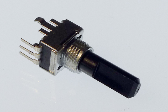
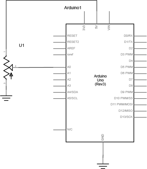
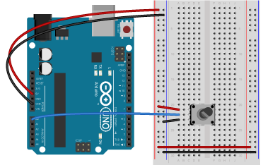
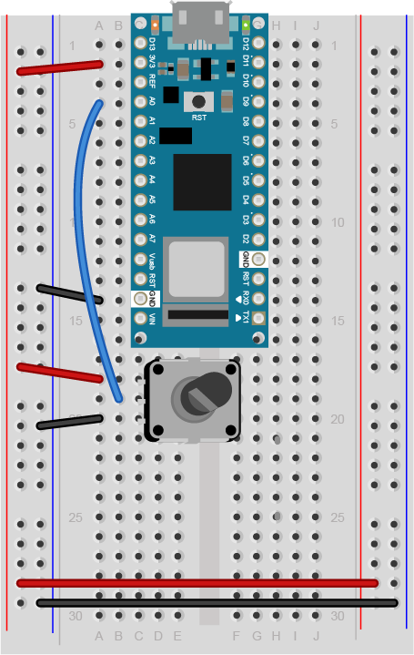
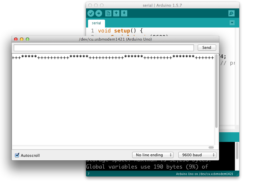
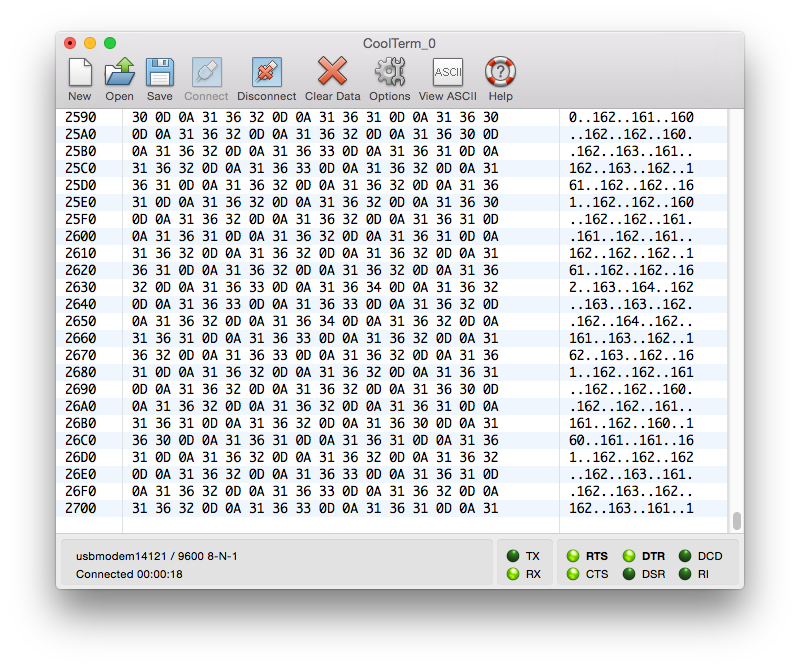
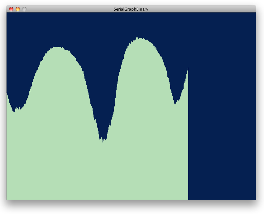


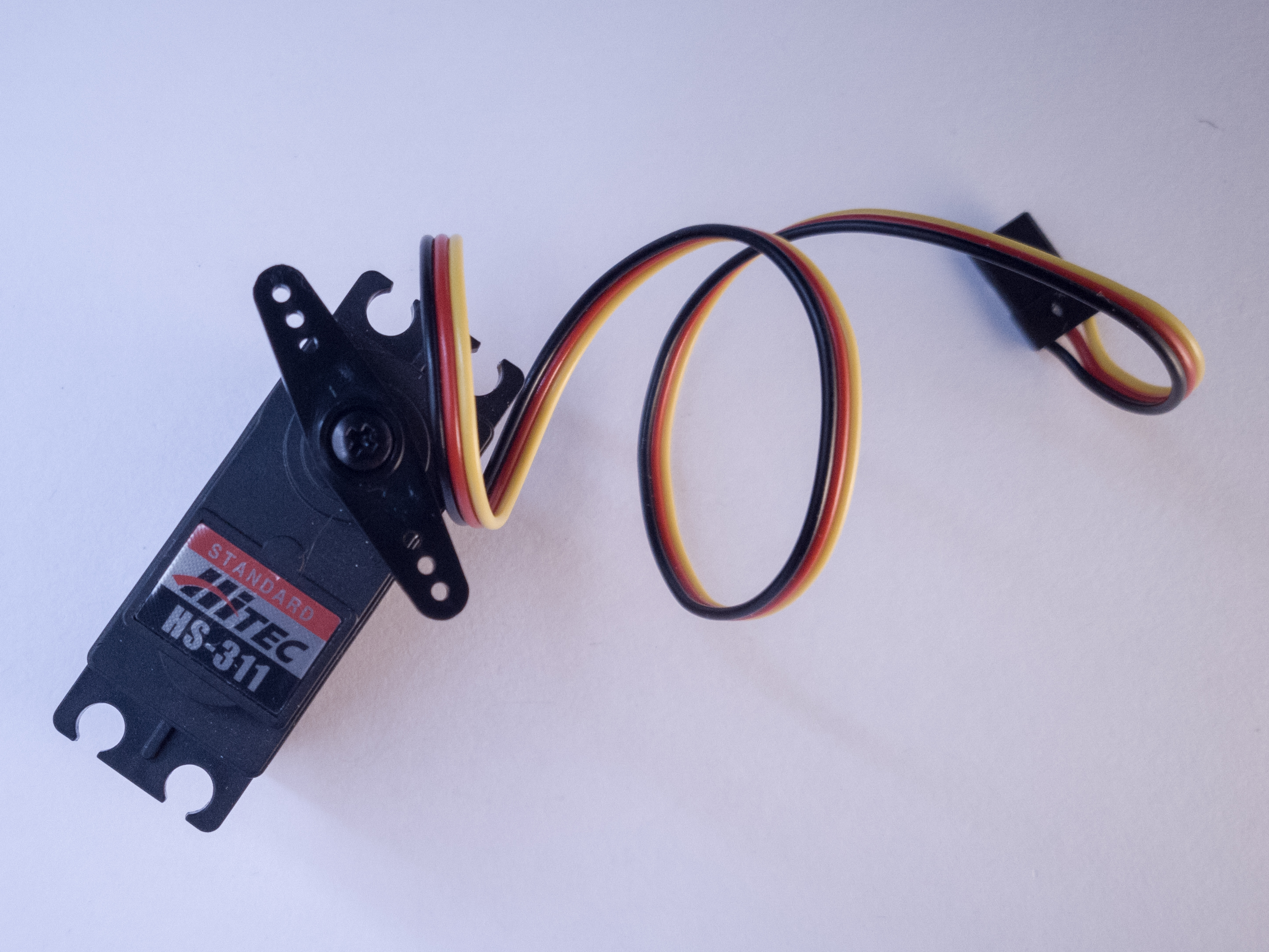

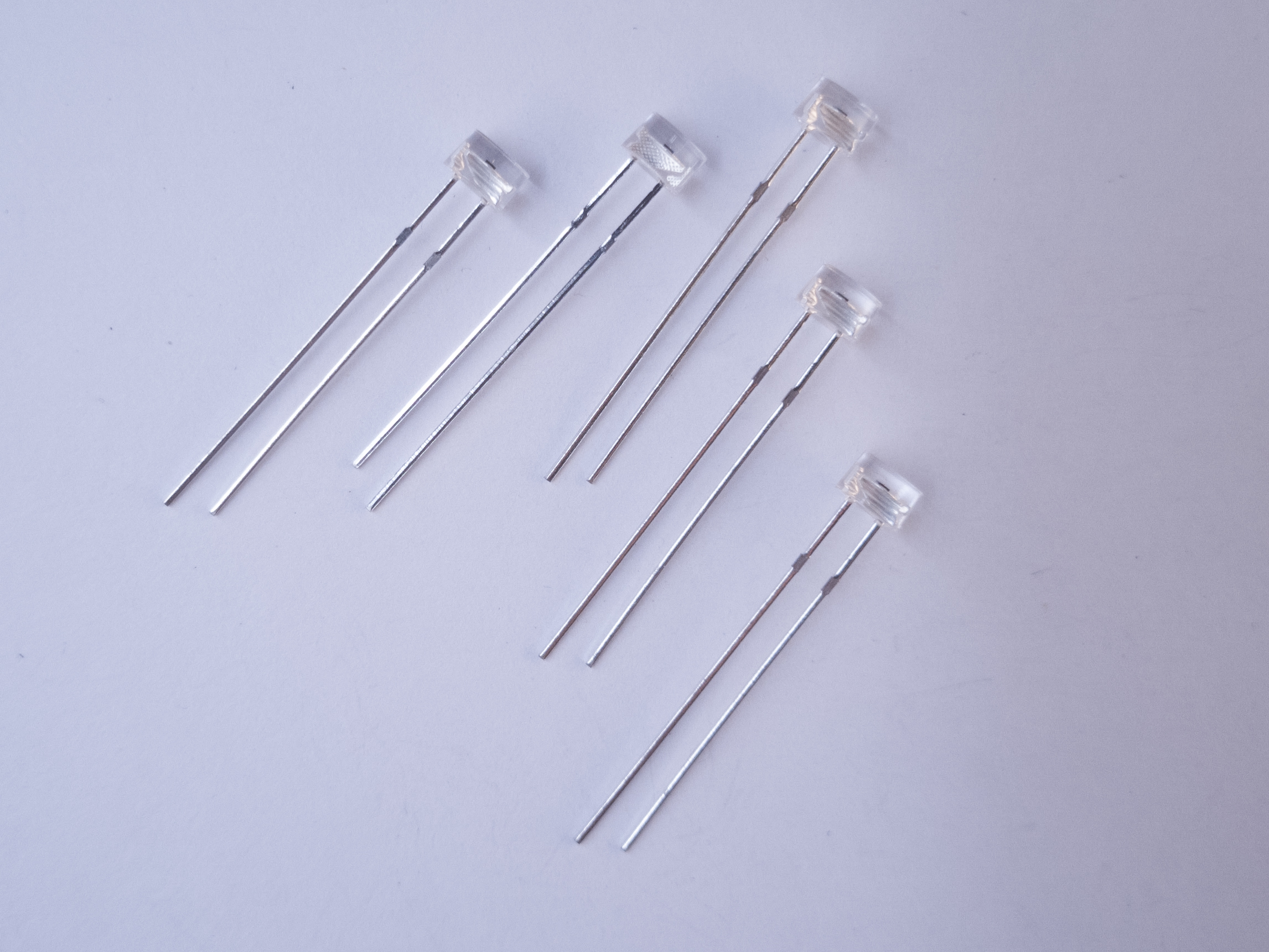


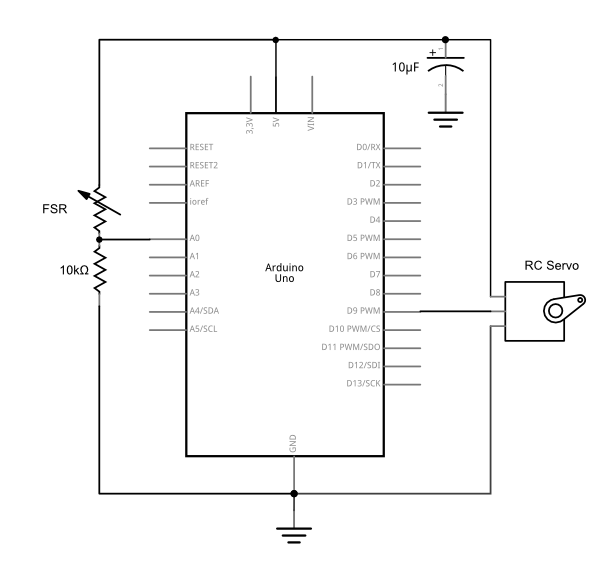
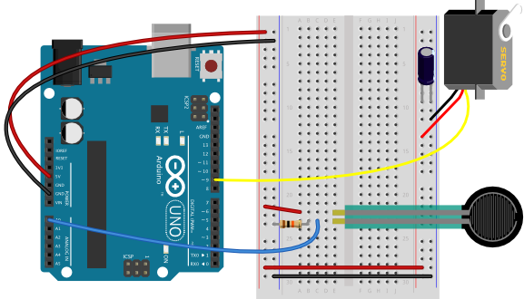
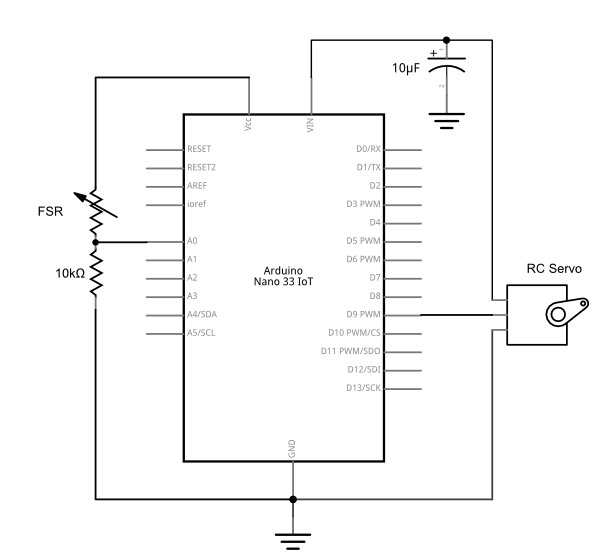
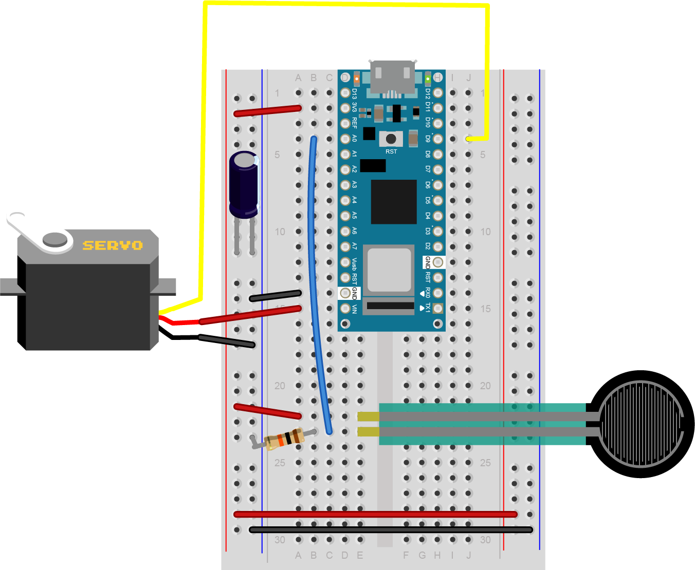
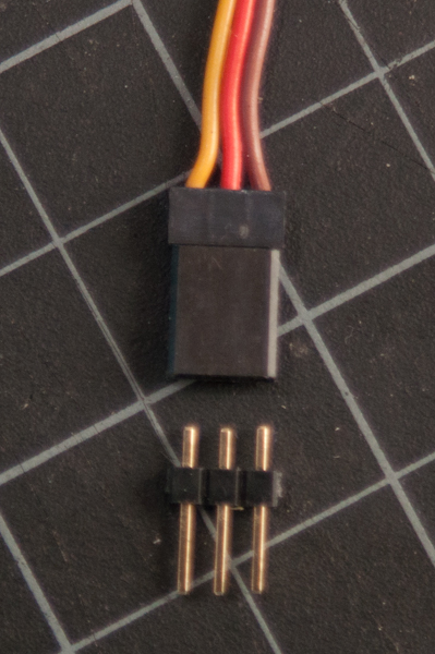
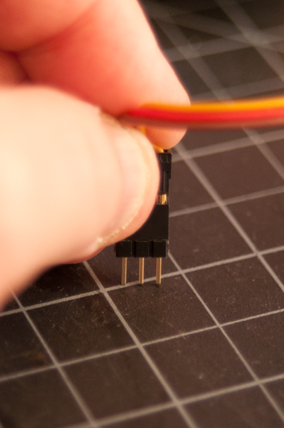
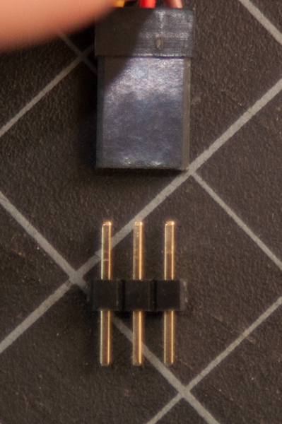
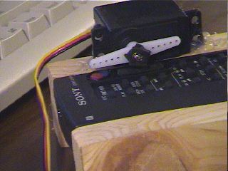

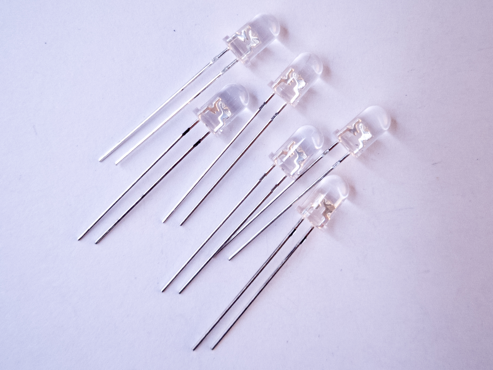
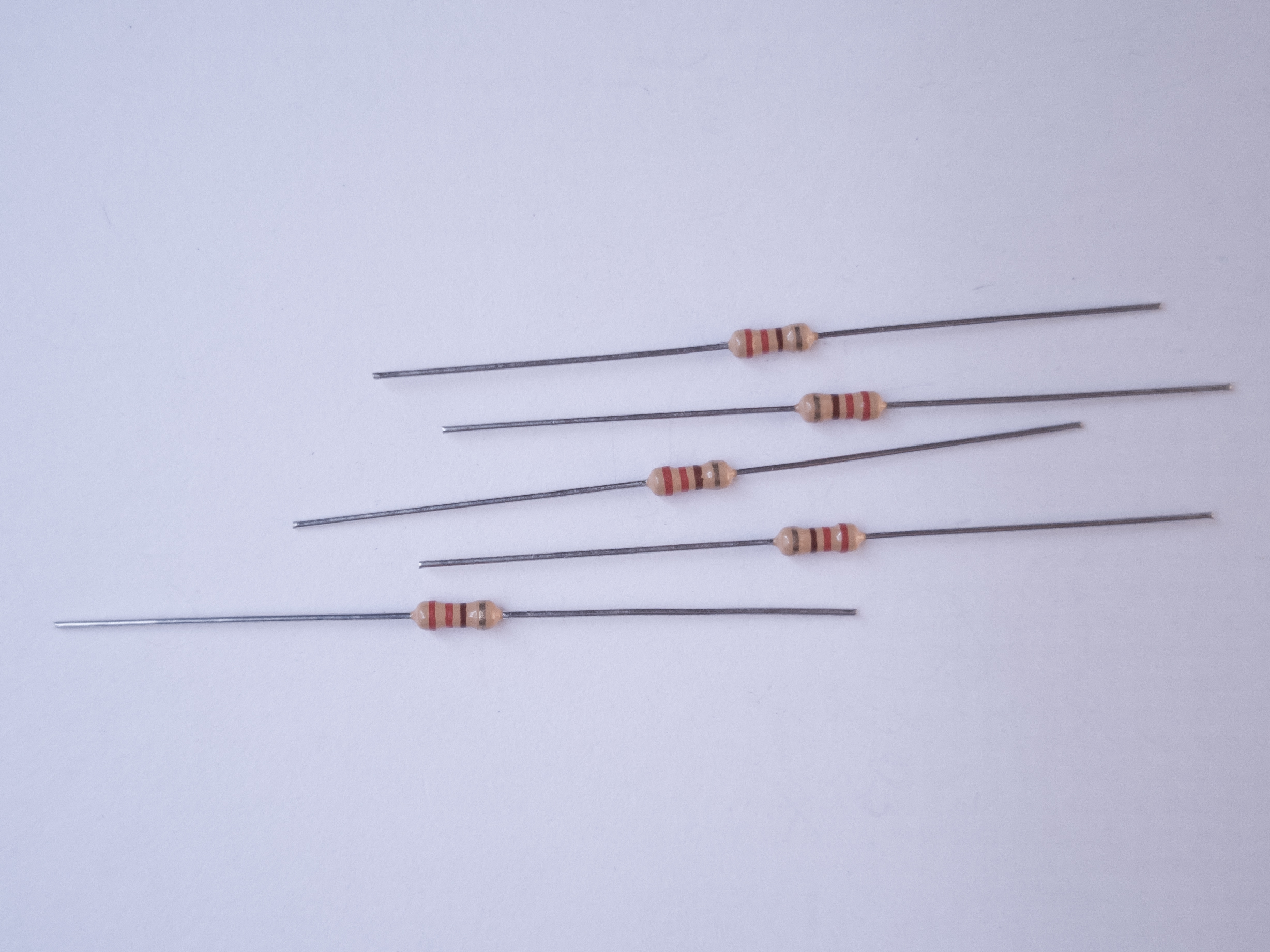

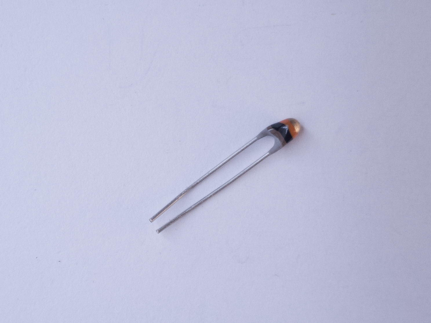
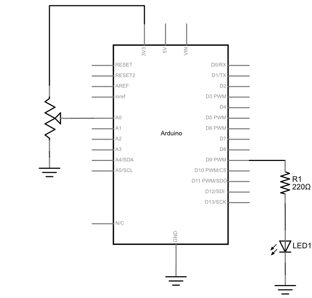
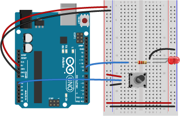
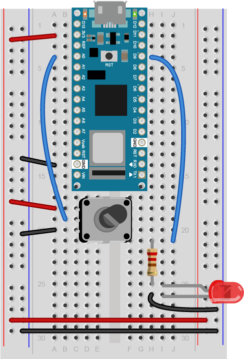

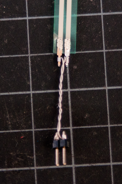
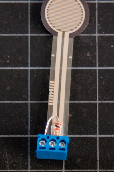
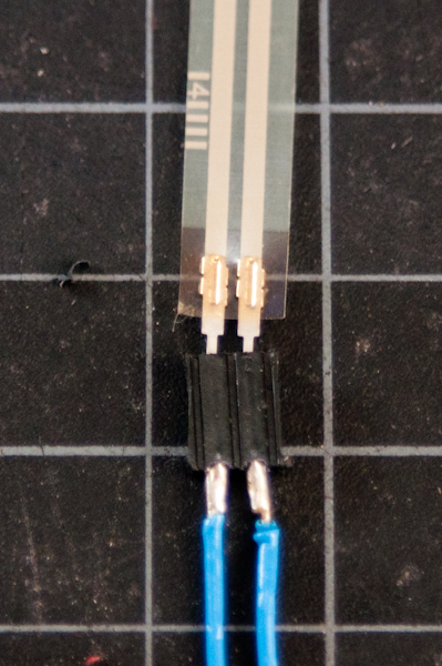
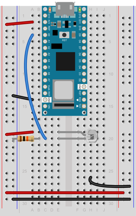
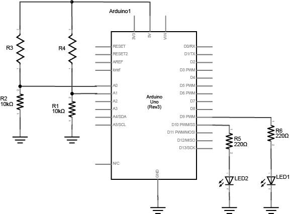

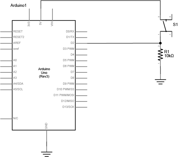
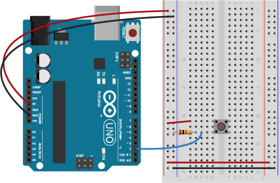
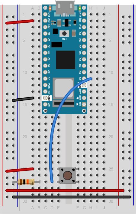
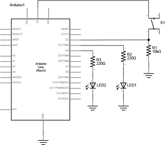
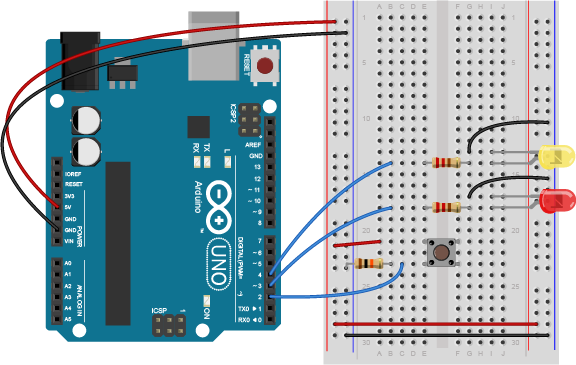
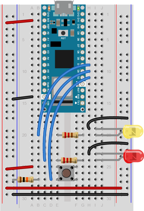
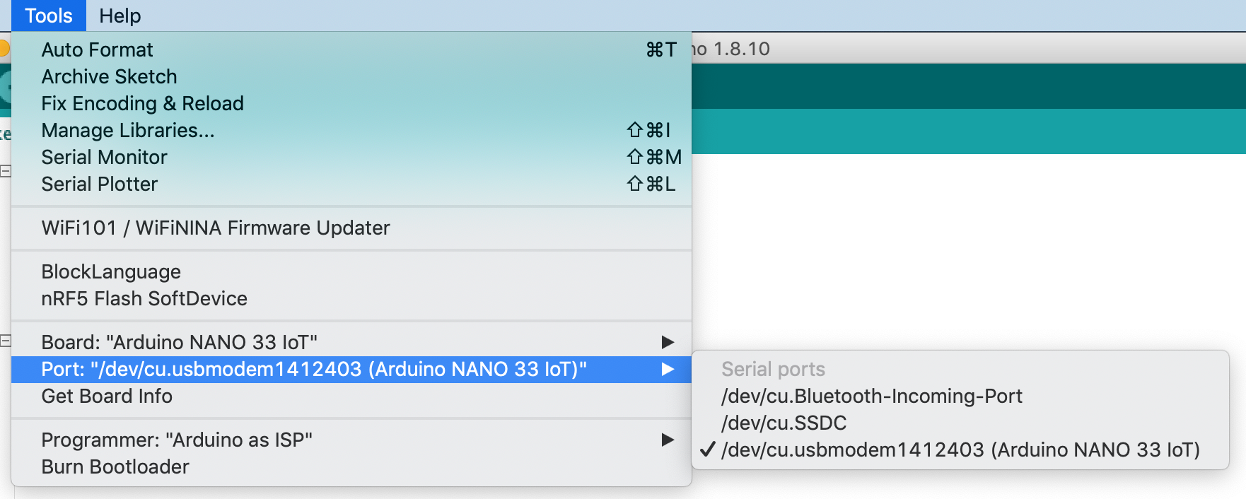
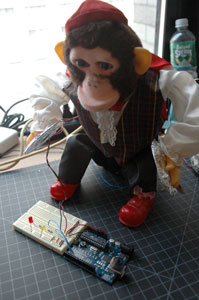
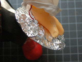
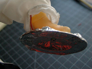
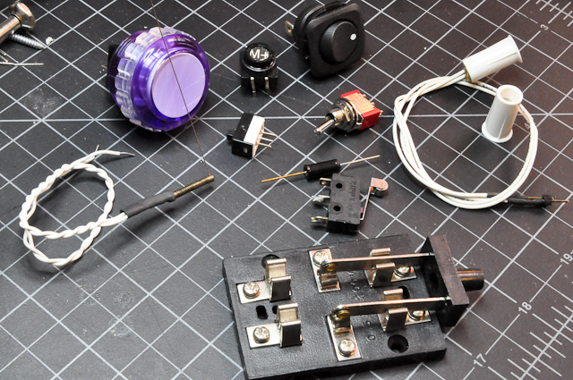
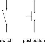
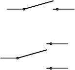
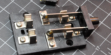
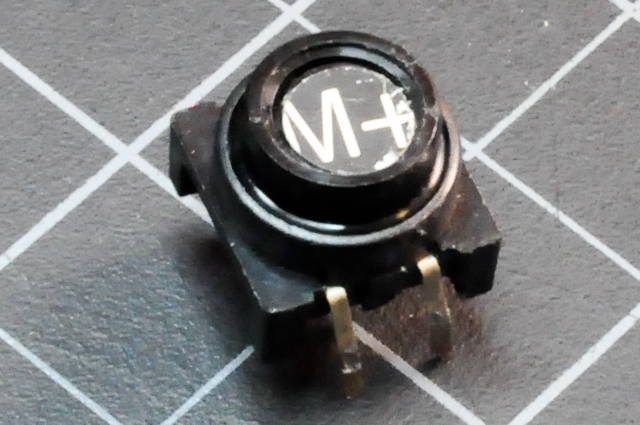
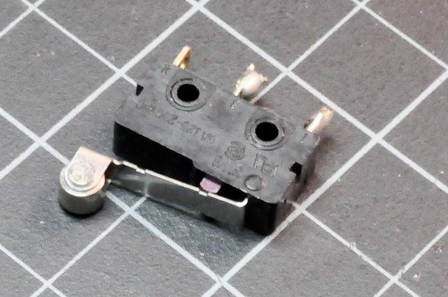
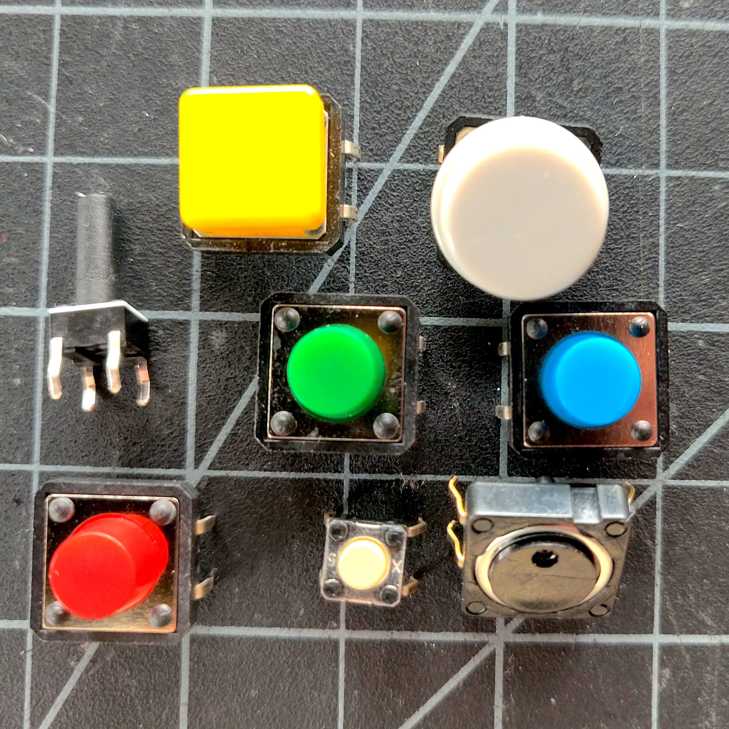
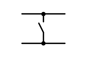
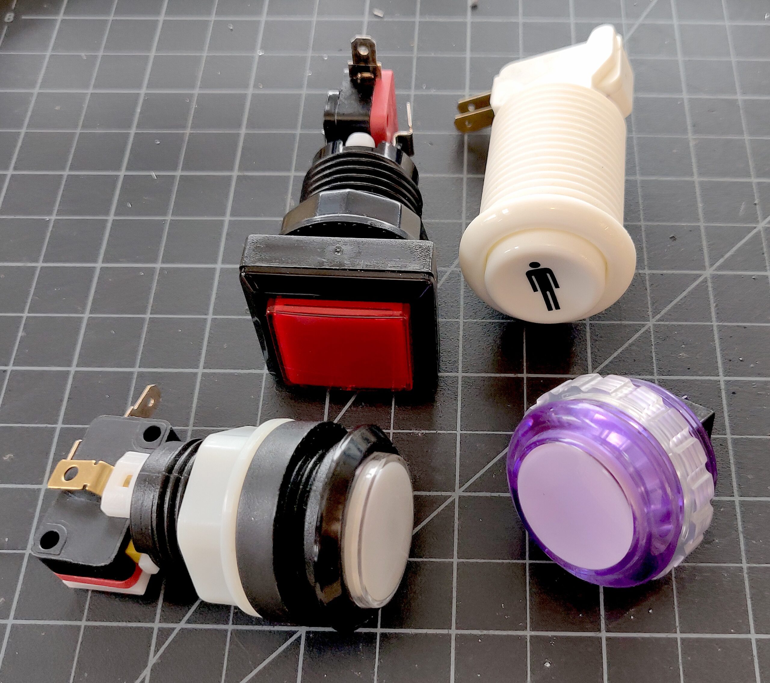
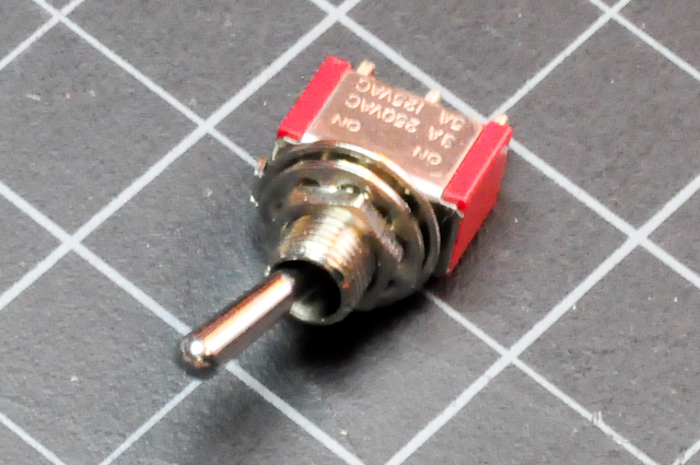
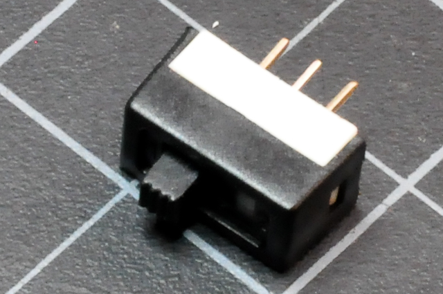
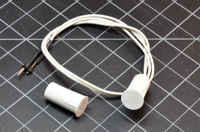
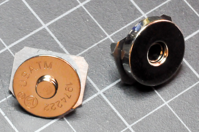
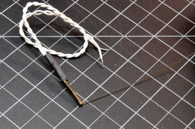


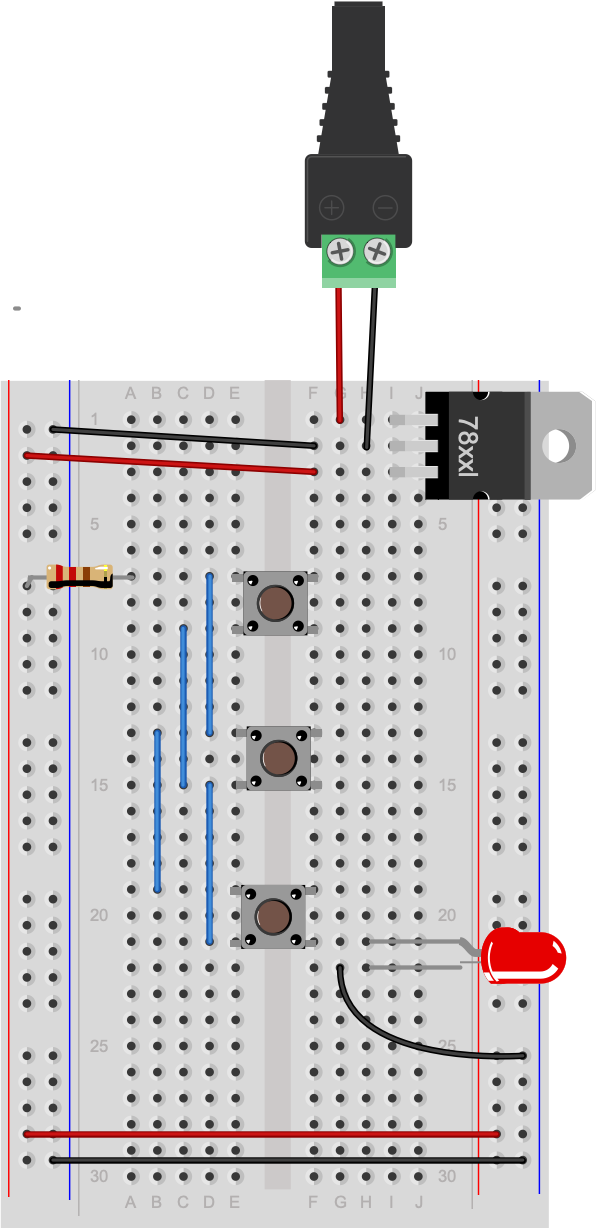
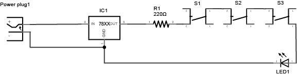
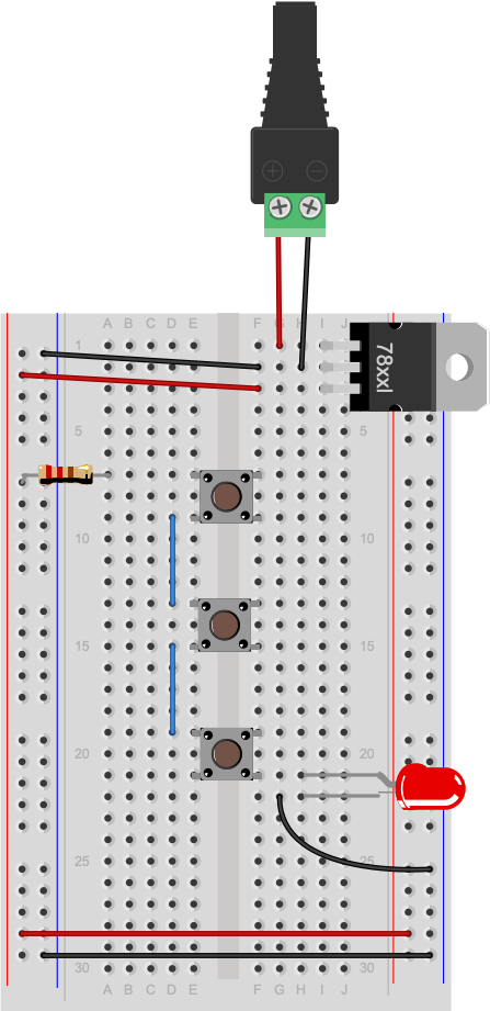
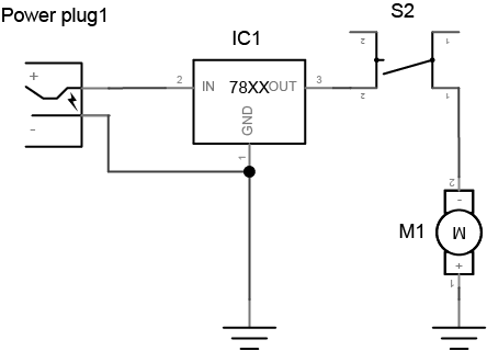
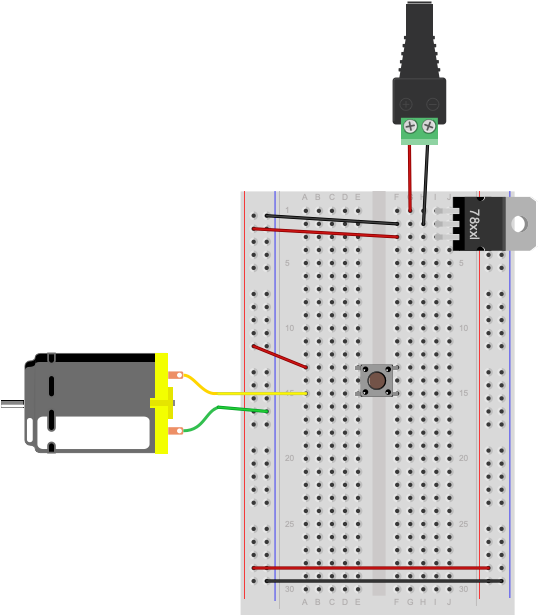
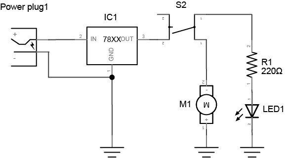
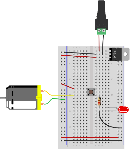


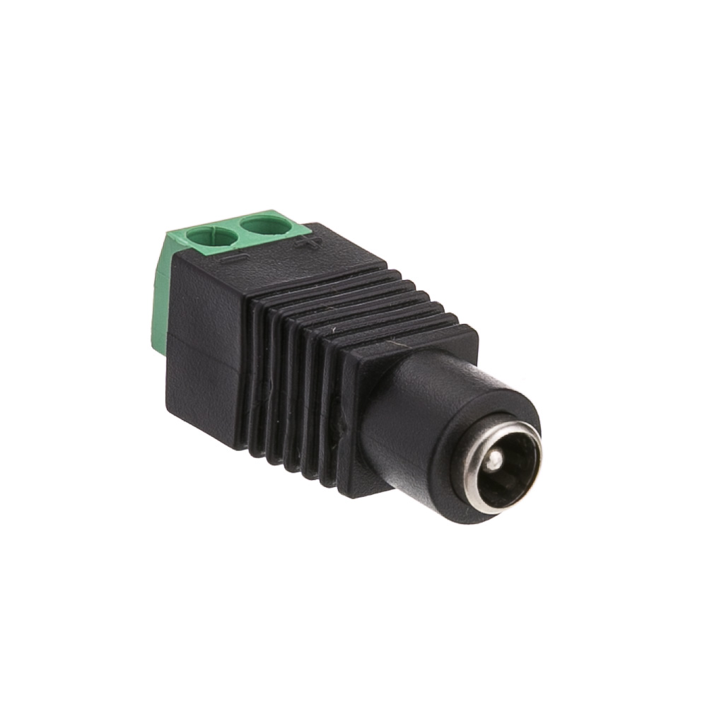
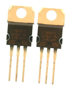

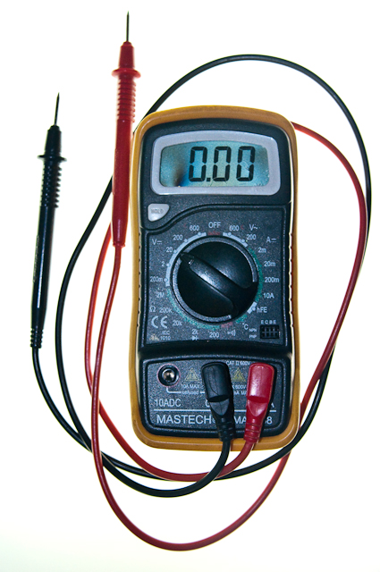

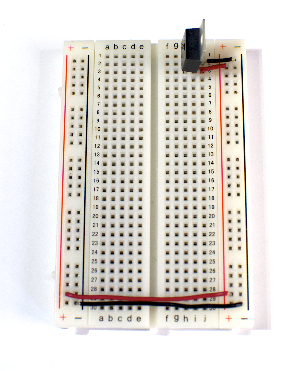
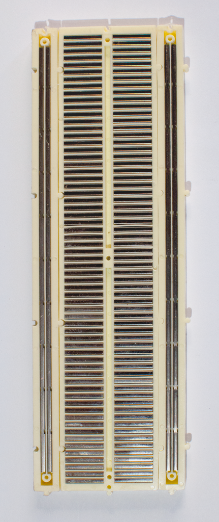
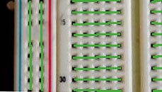
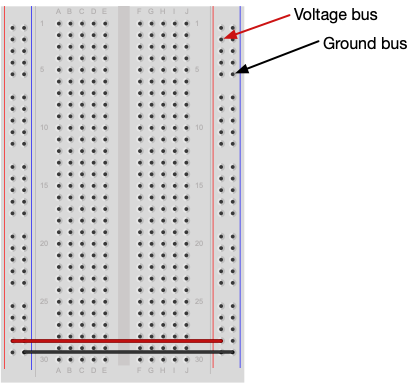
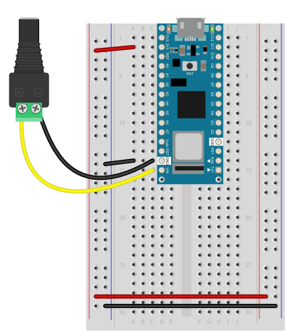
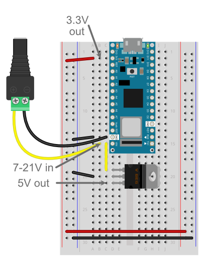
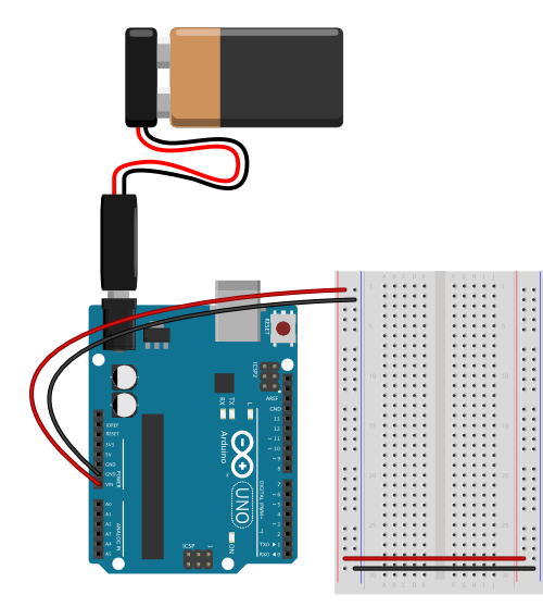
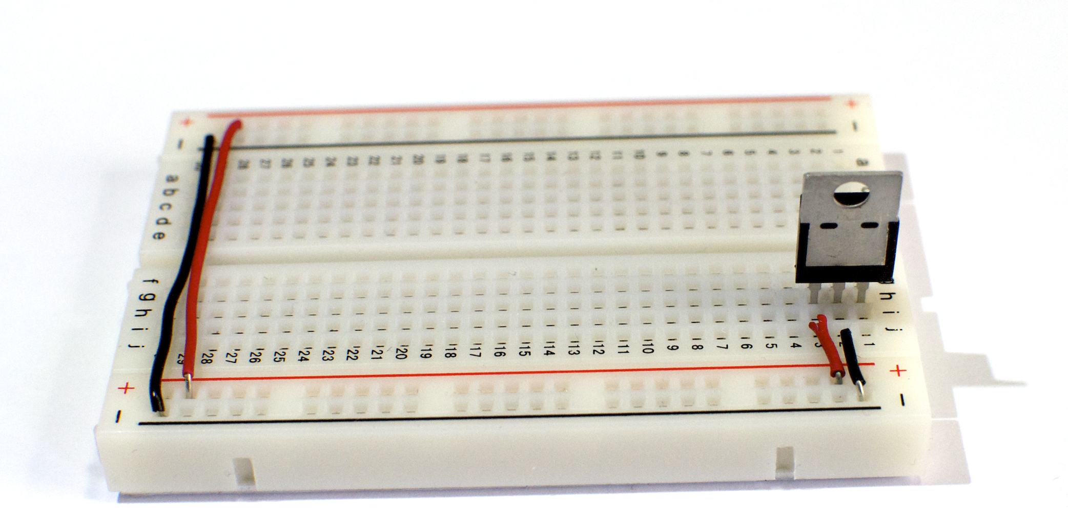
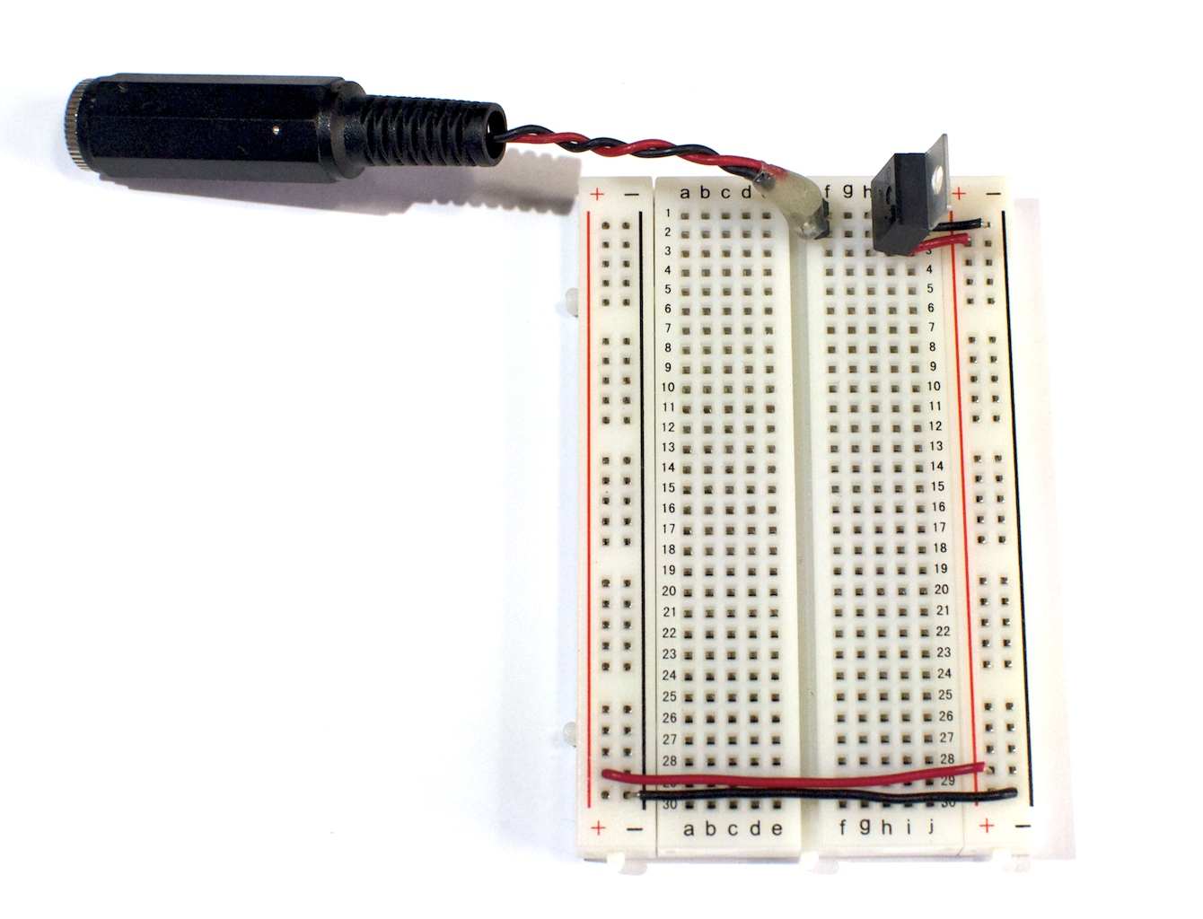
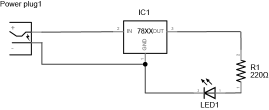
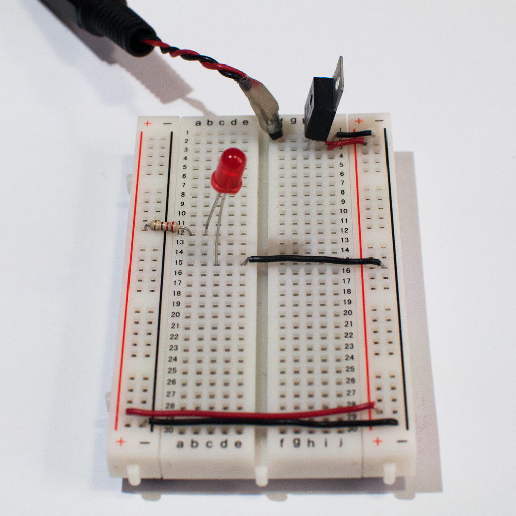

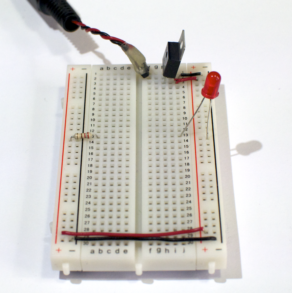
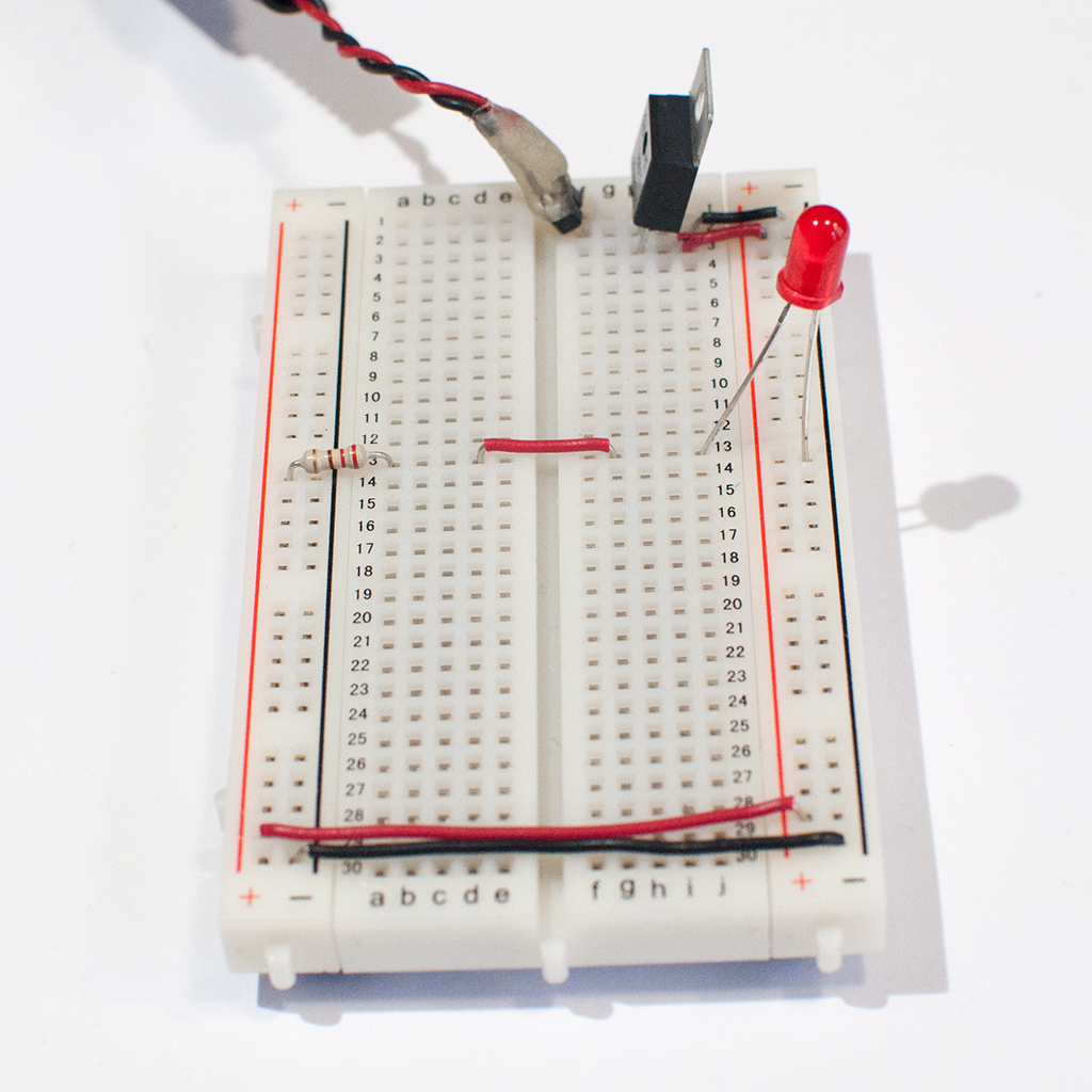
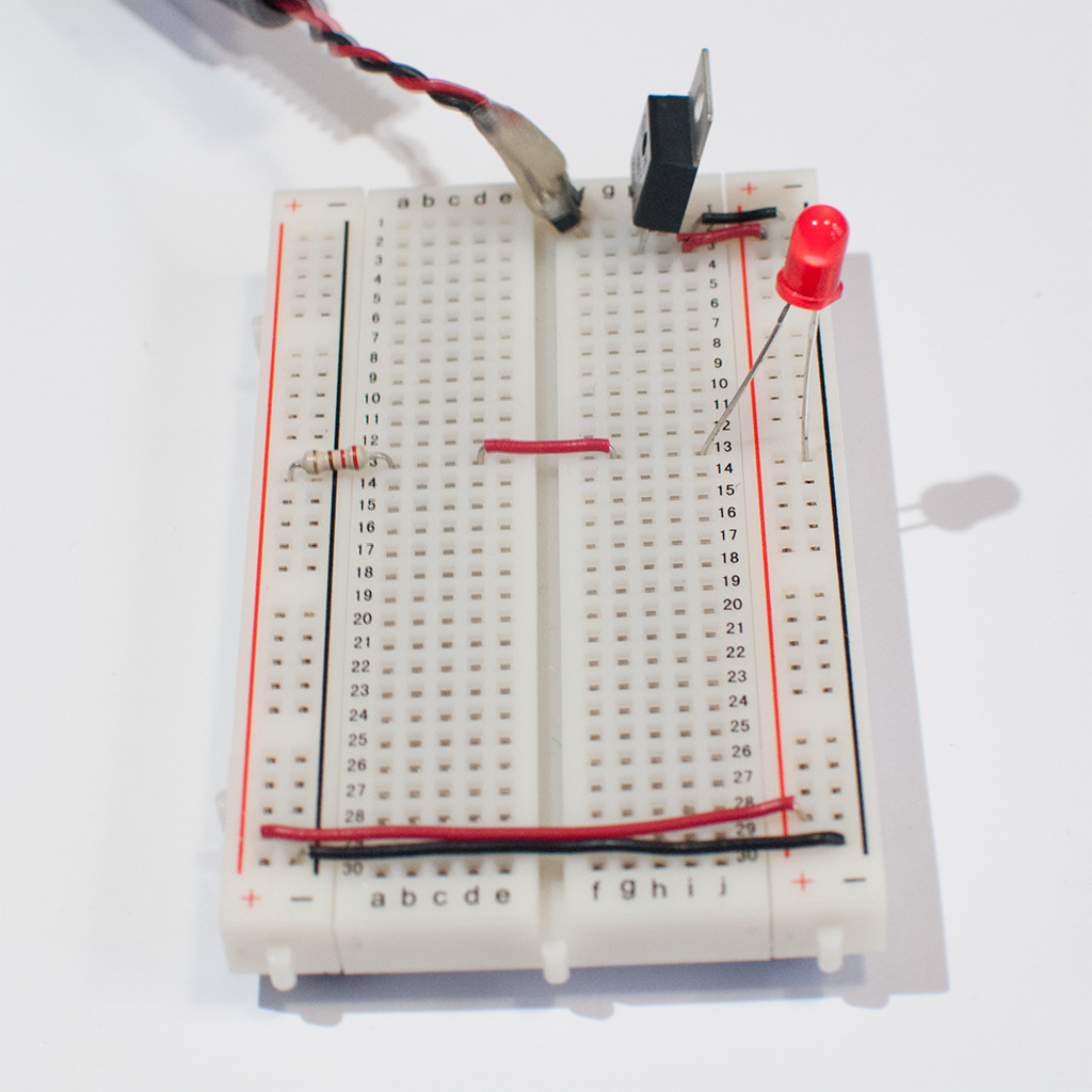

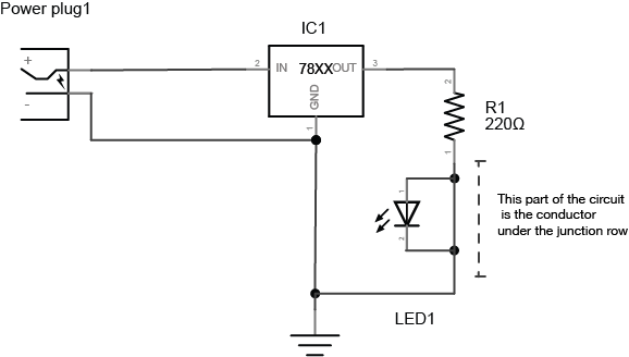
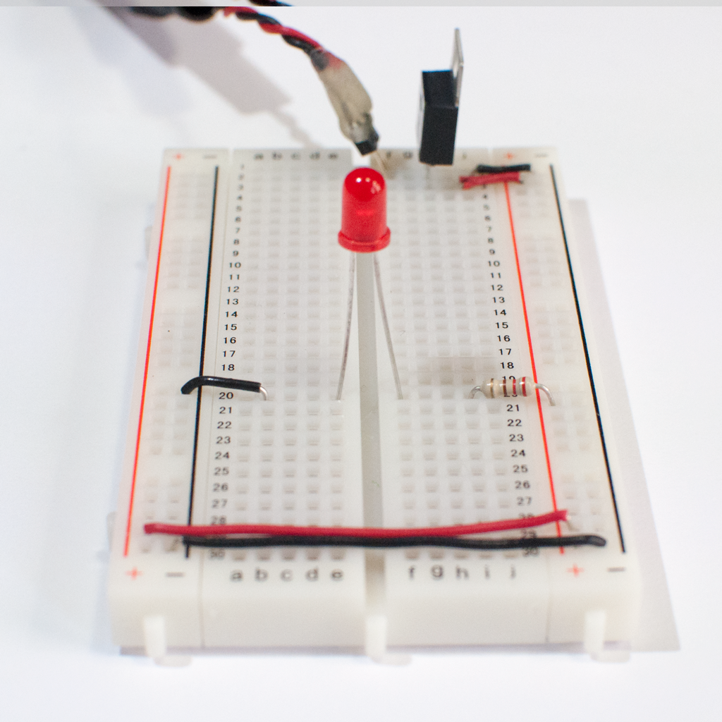
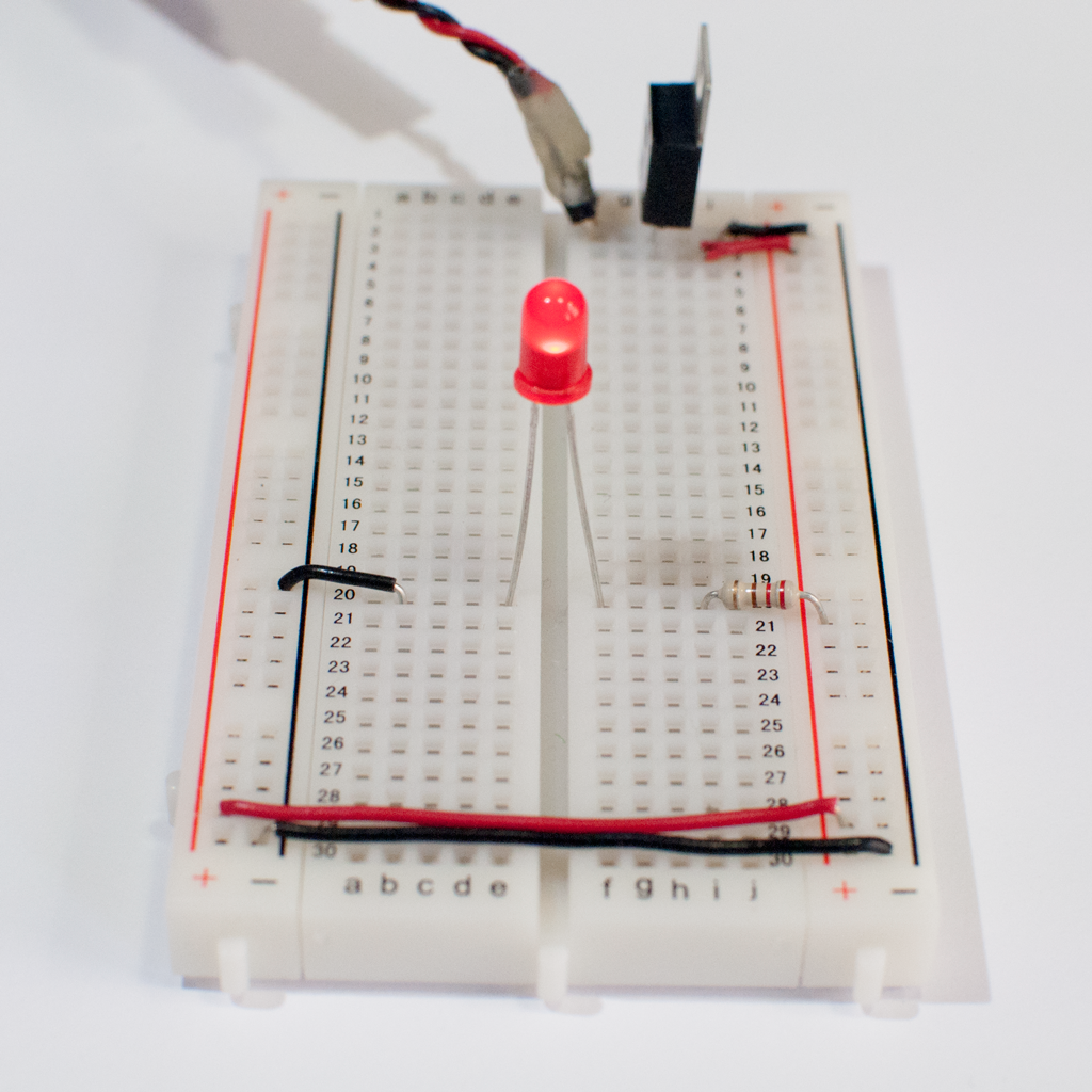
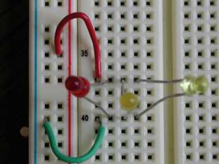
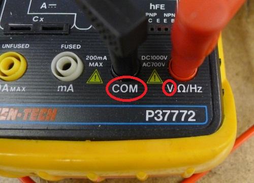
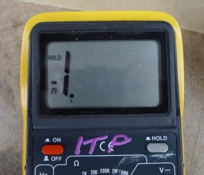
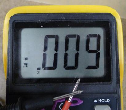
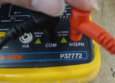
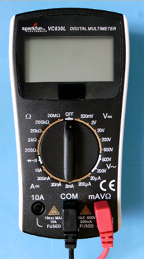
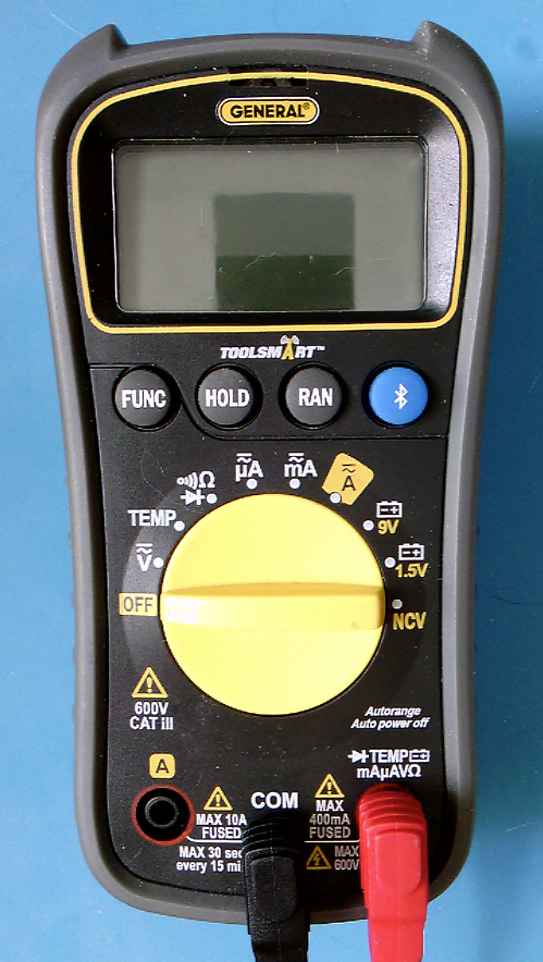
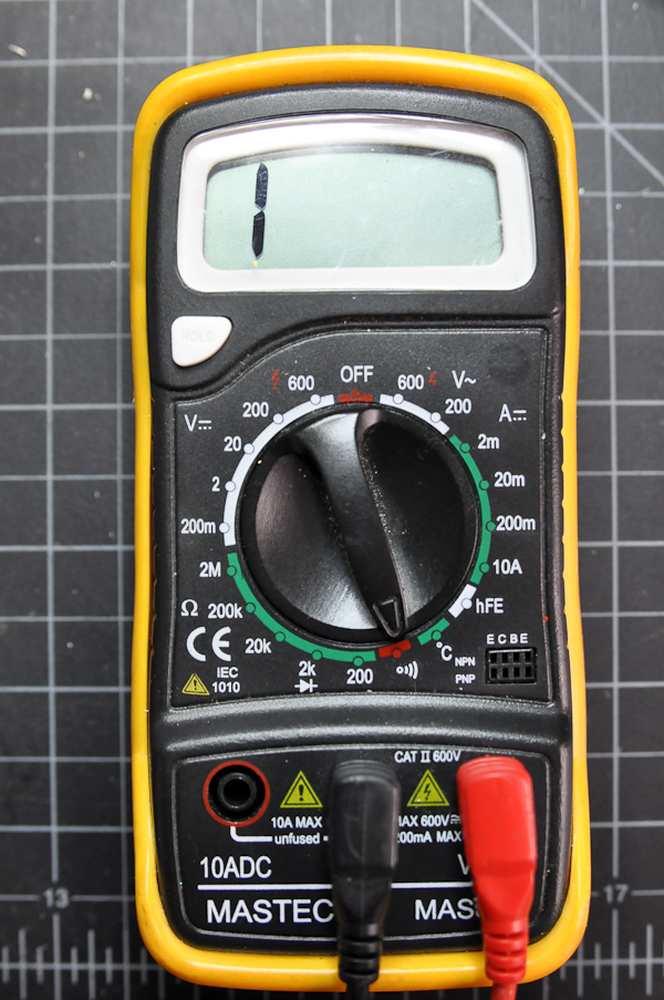
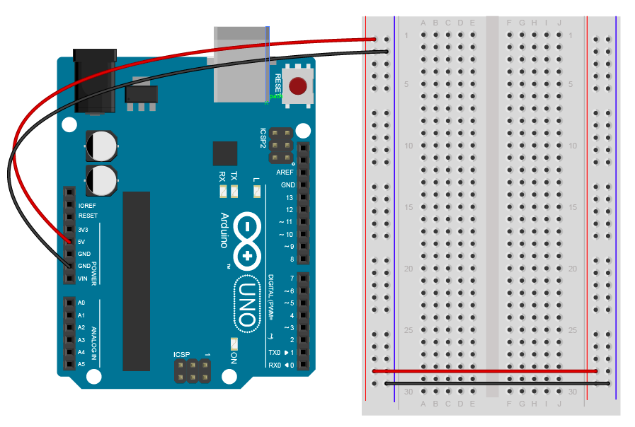
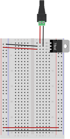
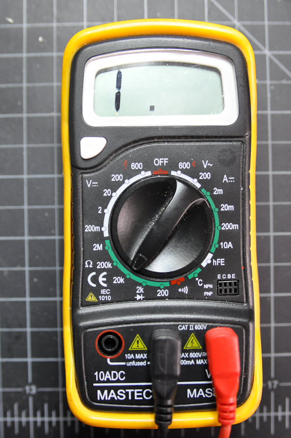
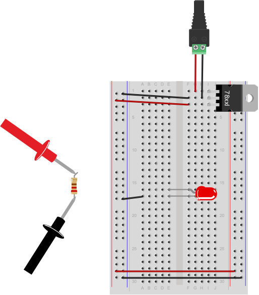
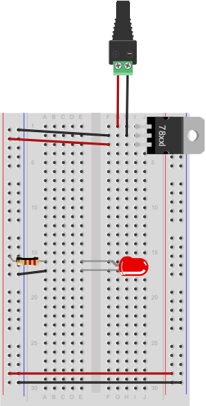
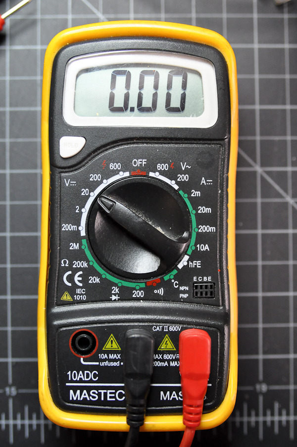
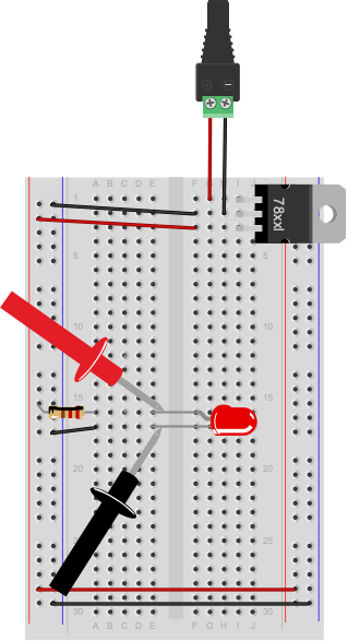
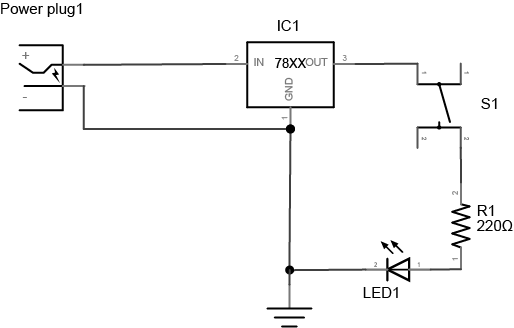
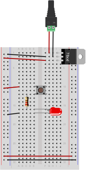
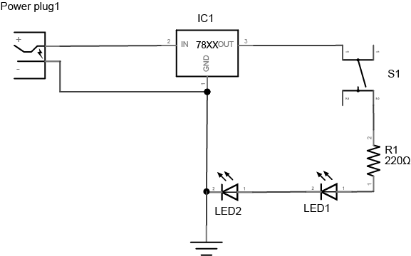
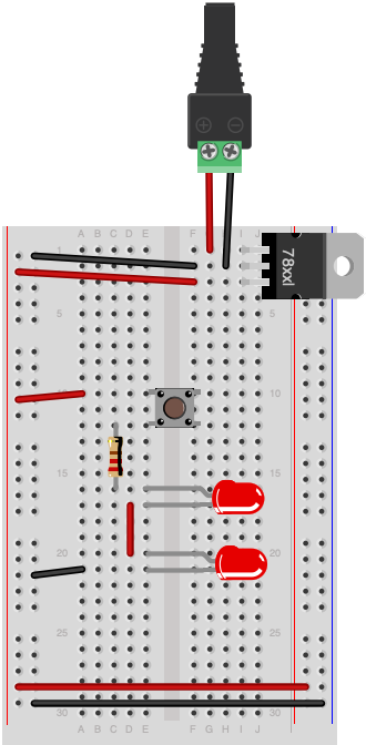
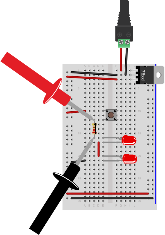
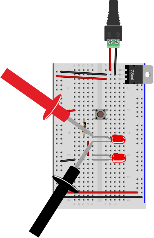
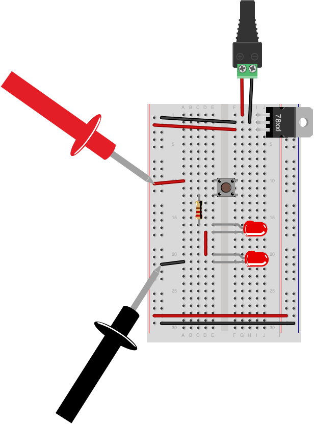
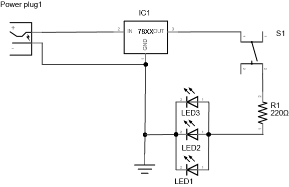
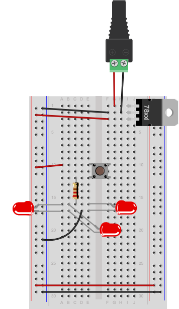
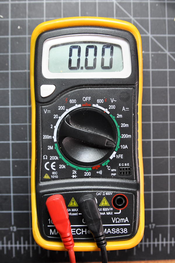
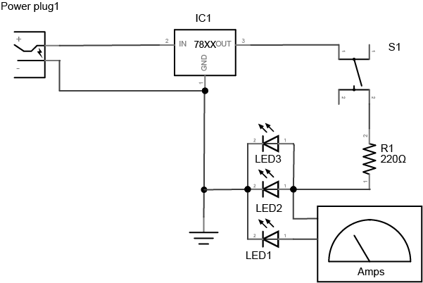
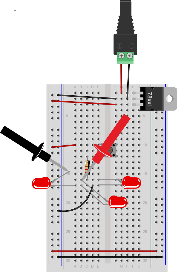
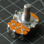
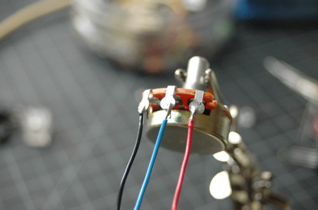
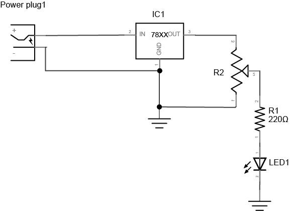
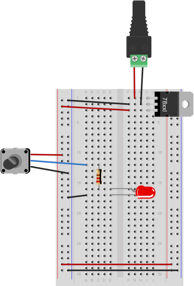
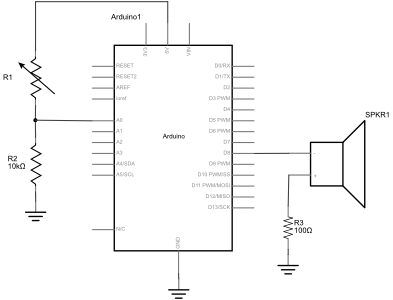
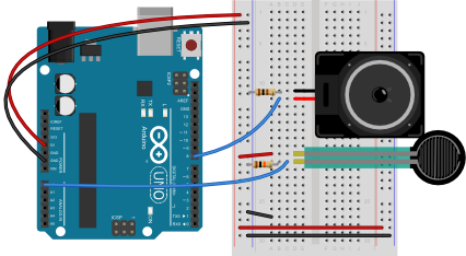
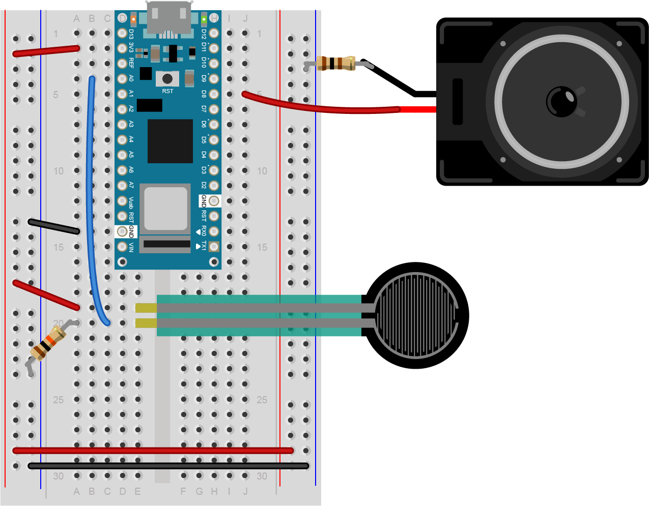
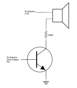
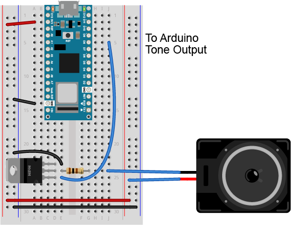
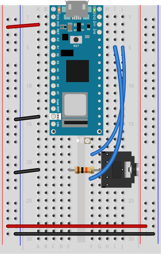

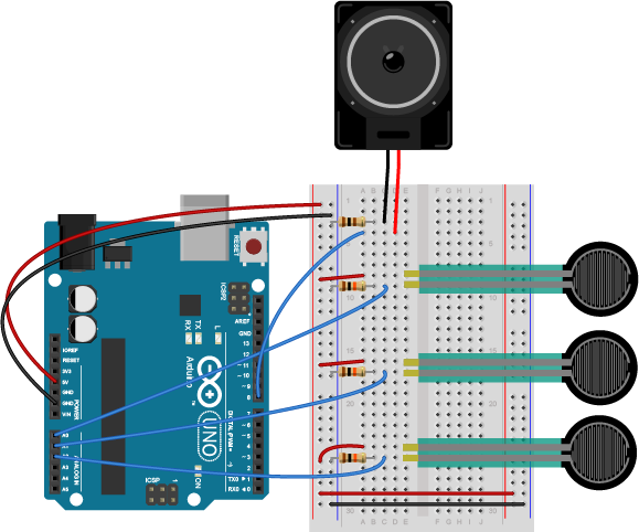
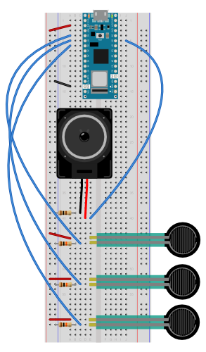
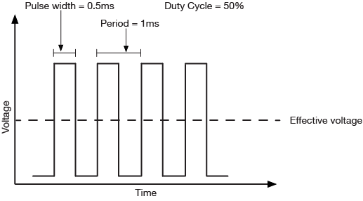
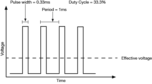
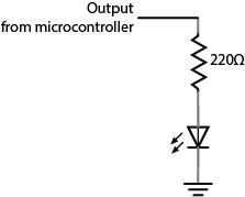
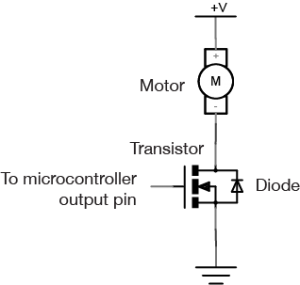
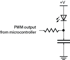
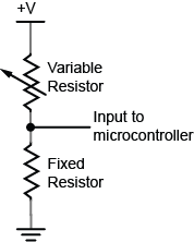
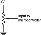