This page lists tools, techniques, and resources that may be helpful to students with differing abilities who want to build the projects described on this site. It is a constant work-in-progress, so if you have suggestions for additions, please let us know.
General Resources
Tactile Schematics
The Physical Computing schematics redesigned for tactile use and a style guide for how to design them, available for download at tactileschematics.com.
APH has a good image library of SVG graphics that’s useful in a variety of educational subjects. The Mathematics ones are likely most relevant here. APH has other useful tools as well, like their Braille Blaster Braille conversion editor, and a few good talking calculators as well.
The Smith-Kettlewell Technical File
The Smith-Kettlewell technical file “was a publication by and for blind and visually-impaired electronics professionals and enthusiasts”. Running from 1980-1998, it covers a range of technical topics with practical advice on topics like soldering, using power tools, electronic components, logic tools and testers, and more. It’s useful for anyone interested in electronics, and formatted in a way that’s accessible for assistive reading devices like screen readers and Braille readers. Thanks to Ken Perry for the link.
Microsoft Visual Studio Code is a decent text editor that is optimized for screen readers. If you have the Arduino IDE installed on your machine, the Arduino Plugin for VS Code makes a good screen reader-friendly editor (thanks Ken, Josh and John Schimmel for the tip). The Arduino Plugin gives you access to most of the tools in the Arduino IDE: boards manager, library manager, examples, compile and upload, and serial monitor. The VS Live Share Plugin allows you to share code live with other users over a network in real time as well. The Accessibility for VS Code page is a useful intro to features in the editor.
On MacOS and Linux, the command line allows you to read input from a serial port just as you would from a file, using the cat command. cat /dev/cu.usbmodemXXXX will open an Arduino’s serial port, if no other application has it open already. control-C will close it. If you’ve got a continually repeating serial output, you may prefer to use the less command instead of the cat command. less /dev/cu.usbmodemXXXX will also print out the serial output, but it will stop after each screenful. Type the spacebar to page through multiple screens, or use the arrow keys to read up and down. Type q to exit.
The Emic2 test-to-speech module is an alternative to using the Arduino IDE Serial Monitor for debugging.It’s a piece of hardware that you can plug it into your Arduino’s serial transmit (TX) or softwareSerial transmit pin, and it will speak whatever you send out the serial pin via Serial.print(), Serial.println(), or Serial.write(). You can get it from Parallax, SparkFun or Adafruit. The Emic2 manual is available online. Here is a barebones code example for the Emic2. (Thanks to John Schimmel of DIYAbility for the tip)
Similarly, if you want a replacement for a dimming LED, use a speaker and the tone() function. An 8-ohm speaker will work pretty well with a 220-ohm resistor in series with it, so you can swap an LED for a speaker and swap analogWrite(pinNumber, x); for tone(pinNumber, x*10); in most cases and get an audible result, because analogWrite() takes a number from 0 to 255 as the second parameter, and a tone() from 200 – 2550Hz is reasonably audible.
Grove Components
SeeedStudio’s Grove components are useful for building projects without a breadboard. The Blind Arduino Blog has some notes on using Grove. In addition to the Grove Shield and the components, there’s also a MKR Connector Carrier that’s compatible with Grove for the MKR series Arduinos. Here are a few useful Grove part numbers from Digikey:
Power supply is a reference to the source of electrical power. Most electronic circuits require a DC power supply. Chances are you have one at home already, and can use it for physical computing projects.
The most common operating voltages for microcontrollers and digital processors are 5V and 3.3V. You can find power supplies in many voltages, but 5V and 12V are common. To convert 12V to 5V or 3.3V, you’d need a voltage regulator. The Breadboard Lab covers how to set that up.
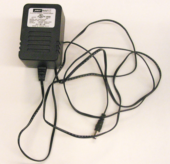
There are many different kinds of DC power supplies but this one shown in Figure 1 is most commonly used at ITP:
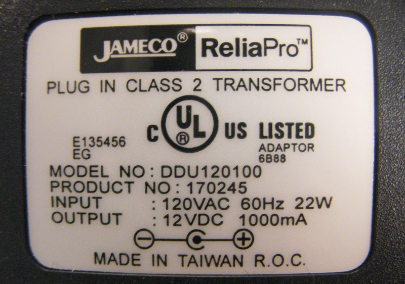
Figure 2. DC supply rating label. This is the back of the supply in Figure 1.
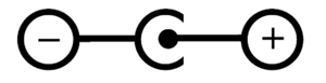
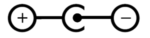
Most power supplies have a rating label that looks something like the one in Figure 2. Make sure you know the polarity of the plug so you don’t reverse polarity for your circuit and damage your components. The diagram in Figure 3 and Figure 4 showing positive tip polarity is on the left and negative tip polarity is on the right. The center positive drawing on the left indicates that the center (tip) of the output plug is positive (+) and the barrel of the output plug is negative (-).
Figure 3. Symbol for a center-positive power supply.
,
Figure 4. Symbol for a center-negative power supply.
Abbreviations
V : Volts A : Amperes W : Watts mA : miliAmperes VA : Volt Amperes VAC : Volts AC VDC : Volts DC DC : Direct Current AC : Alternating Current
Testing your power supply
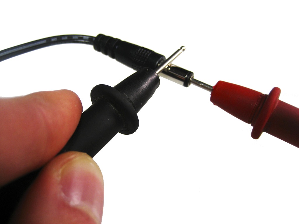
It is always good practice to test a power supply before using it for the first time. The example below will show how to test a power supply with positive polarity. If you have a negative polarity power supply, then you will get a negative reading. You should then switch the position of the multimeter probes.
Figure 5. Red probe goes into the tip Black probe touches the barrel
Plug your power supply into an AC outlet.
Turn on your multimeter and set it to read DC voltage.
Take the red (positive) probe from your multimeter and stick it into the end of the power supply plug as shown in Figure 5.
Take the black (negative) probe from your multimeter and carefully touch it against the barrel of the plug without touching the tip or your red probe. If you make a connection, you will be creating a short circuit.
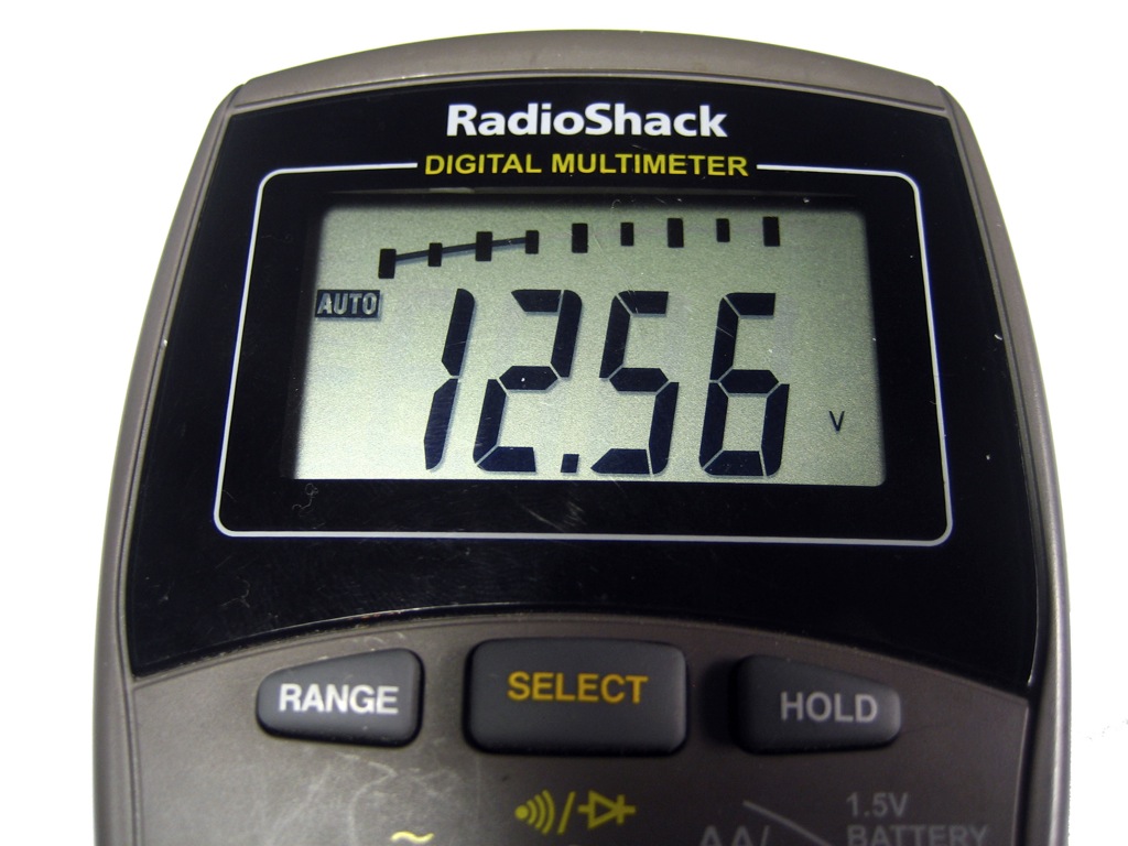
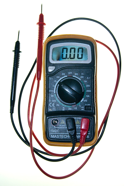
On your multimeter you should see a reading of the voltage coming from your power supply. If you are checking a 12V power supply and your multimeter shows “12.56V” everything is fine and dandy as shown in Figure 6. If you get a reading of “-12.56V” then your probes are attached in reverse. If this happens and you are positive you connected your probes correctly, double check the polarity on your power supply’s label and make sure the circuit you will be powering with this unit is designed to handle this polarity.
Figure 6. Multimeter displaying output DC voltage
If the voltage showing on your multimeter is more than half a volt or a volt off its rating, then you most likely have what is called an unregulated power supply. The 12V Jameco power supply we used in this example is a regulated one, so that is why the voltage we received was so close to the voltage it was rated for. Some 12V DC power supplies will actually read at 15-16V.
Unregulated power supplies run high on voltage when there is no load. When the supply starts to take a load, the current consumed will go up, and the voltage will drop. There are (more expensive) constant current supplies and constant voltage supplies, which will adjust their current or voltage when there is a change in the voltage or current, respectively. For more on this, here’s a decent explanation.
This is a reason why we use voltage regulators, and why most microcontroller modules have them built in. They’re designed to take a range of voltage and output a constant, lower voltage. In a sense, a voltage regulator is a very minimal constant voltage supply.
Powering an Arduino Project from a Mobile Phone Charger
Many people have old mobile phone chargers around the house, and wonder, “Can I use this for powering an Arduino project?” Generally, you can. Just get a USB cable with the appropriate connectors to connect the phone charger to your Arduino. Most phone chargers output 5V and a few hundred milliamps, which will power an Arduino, some sensors, and some LEDs. If you try to program your Arduino from the phone charger’s cable, though, you may be out of luck. Many phone chargers come with USB cables that contain only the power connections, not the data connections.
Matching A Power Supply to an Electronics Device
To determine whether a power supply is right for your project, you need to note the voltages that each component operates at, and the current they consume, and make sure your power supply can provide the right amount of power.
Imagine you’re making a project that includes an Arduino, a few LEDs, some pushbuttons, some potentiometers or other variable resistors, and perhaps a speaker. The Digital In and Out lab and the Analog In lab, and the Tone Output labs all describe projects that meet this description. All of the components other than the Arduino in this project are powered from the Arduino voltage output. None of the external components consume more than a few milliamps each. The whole circuit, Arduino included, will likely consume less than 200 milliamps of current. Here’s a breakdown, measured using an LED and a potentiometer:
Arduino Uno, no external components: 0.04A (40 mA)
Arduino Nano 33 IoT, no external components: 0.01A (10 mA)
LED: 4 mA
potentiometer connected as analog input: 0.29 mA
8-ohm speaker, playing a tone on the output pin: 0.5 mA
A phone charger, which supplies 5 volts and about 500 milliamps to the Arduino, would do the job fine. The Arduino Uno operates on 5 volts, and the Arduino Nano 33 IoT, which operates at 3.3 volts, has a built-in voltage regulator that will convert the 5V to 3.3V.
If you had a 12-volt supply like the one above, you could also use it for these projects. The Arduino Uno has a voltage in plug which matches it, and can take up to 15V. An on-board regulator converts the higher voltage input to 5V. The Nano 33 IoT has an on-board regulator that can accept up to 20V in its Vin pin (physical pin 15), so if you connected a DC power Jack and connected the ground of the 12-volt supply to the Arduino’s ground and the positive connection of the 12-volt supply to the Arduino’s Vin pin, your project would operate.
Arduino, Servomotor
If you’re controlling an RD servomotor from an Arduino as shown in the Servomotor lab, you need to consider the current a bit more. A servo like the Hitec HS-311 , which is popular in physical computing projects, operates at 4.8 – 6.0V, so it can get enough voltage from an Arduino’s voltage output. When it’s idle, it consumes about 160 mA with no load on it. It can consume up to 3-400 mA with a heavy load, however. It’s wise to plan your project for each component’s maximum current consumption, so a single servo and Arduino could consume up to 440 – 450 milliamps at 5 volts. That is almost the limit of what a laptop computer can supply via USB, and it’s the limit of some smaller phone chargers as well. If you were controlling multiple servos, you wouldn’t have enough current.
Arduino Uno, no external components: 0.04A (40 mA)
Arduino Nano 33 IoT, no external components: 0.01A (10 mA)
HS-311, heavy load: 400 mA
Arduino, DC Motor or Lights
When you start powering larger DC motors, DC lights, or other high-current loads, you have to calculate the voltage and current before you select a power supply. You generally work from the component that has the highest consumption and work from there.
For example, controlling an LED light bulb like this one would require a 12V DC power supply for the bulb. It consumes 11 watts of power, and watts = volts * amps, so it consumes about 917 milliamps of current at 12 volts. The transistor and Arduino that might control it could be powered via the same 12-volt power supply, and would consume the same amounts as in the examples above.
Motor projects and addressable LED projects often consume the most electrical energy and are the most complex to power. A typical addressable LED like a WS2812, aka NeoPixel LED, consumes between 60 and 80 mA of current at 5 volts. When you have a string of 60 of them, that’s 3.6 amps of current! These definitely can’t be powered from a typical DC wall supply. When you reach that level of complexity with a project, consult your components’ datasheets or your instructors for more guidance. The videos on electricity, current, and power are helpful on this subject as well.
Sometimes you want to communicate between a microcontroller and a mobile device. Tom and Jeff show you how to use your laptop as a web server to connect a p5.js sketch on your tablet to to your microcontroller via a serial port.
This lab will introduce you to a few basic electronic principles by trying them in action. You’ll learn how to measure voltage, amperage, and resistance using a multimeter. You will also learn about components in series vs. parallel and be introduced to Ohm’s Law in practice.
Introduction
This lab will introduce you to a few basic electronic principles by trying them in action. You’ll learn how to measure voltage, amperage, and resistance using a multimeter. You will also learn about components in series vs. parallel and be introduced to Ohm’s Law in practice. For more information on the theory behind this lab, please check out these notes.
When you’re building electronics, you run into problems all the time. Diagnosing those problems relies not only on a good theoretical knowledge of how circuits work, but also on practical knowledge of how to test them. The most common tool for testing circuits is the multimeter, a device that can measure current, voltage, resistance, and electrical continuity. More expensive multimeters can also measure other electrical properties, but if you can measure these four, you can diagnose most common circuit problems.
What You’ll Need to Know
To get the most out of this lab, you should be familiar with the following concepts beforehand. If you’re not, review the links below:
Before you get started, you will want to make sure your meter is working. This is a particularly good idea if you’re using a meter that lots of other people use, such as the ones at ITP. Here is how to test that:
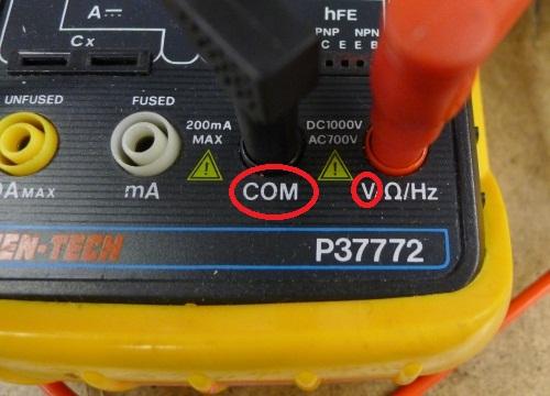
Insert the two probes. Insert the Black probe in the “COM” jack. This is the COMmon, or ground, connection. The Red probe should be in the “V” jack (Figure 11). This connection is for measuring voltage. It can also be used to measure resistance in Ohms, or frequency in megaHertz, on the meter shown here.
Figure 11. Multimeter detail, showing the holes for the probes.
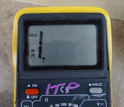
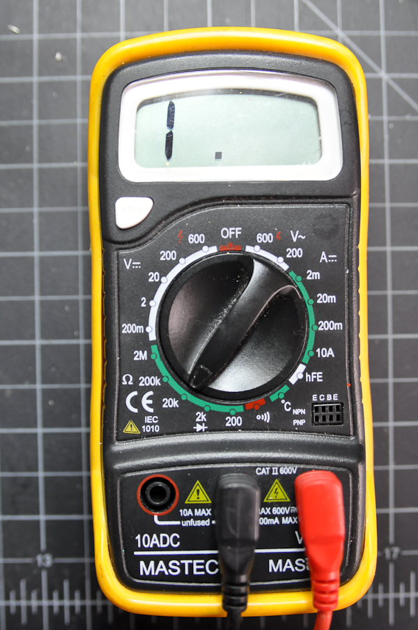
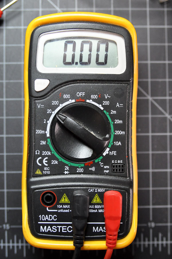
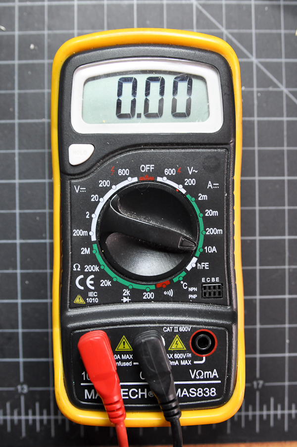
Turn the function knob to the Diode/Continuity Function and switch the meter on. If the word “Hold” appears on the screen, press the hold button once to disable the hold function (not all meters have a clearly labeled Hold function; check your meter’s manual to be sure – see Figure 12). This function is used to hold a value onscreen after you remove the probes from a circuit. The “1.” on left picture means the value is out of range now.
Figure 12. This multimeter’s hold button is on the right side below the screen.
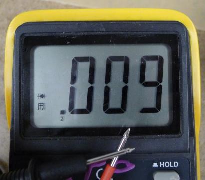
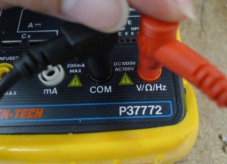
Touch the tips of the probes together. The meter will beep and the display value should be less than 0.01 (Figure 13). If it works, congratulations! you have a usable meter. If not, try to push the plug of the probes to improve the contacts (Figure 14). In many cases the failure is caused by loose contact of the jacks. In other cases, you might have a weak or dead battery.
Figure 13. Detail of .a meter measuring continuity. The meter is should be making a beeping sound in this case.
Figure 14. If the meter is not working correctly, check to see if the probes are plugged in properly.
The Controls on a Meter
Different meters have different controls, but most meters will have the following:
Voltage: This setting is generally broken up into Volts DC, indicating that the polarity of the voltage will not change, and Volts AC, indicating that the polarity will alternate.
Amperage: This setting measures the current in a circuit. Again, it’s usually broken up into AC and DC. There are commonly two holes for the positive probe to measure current, one that’s low amperage and the other that’s high amperage. Don’t try to measure high amperages with the positive probe in the low amperage hole or you will damage the meter.
Resistance: Resistance is measured in ohms. This function is sometimes grouped with the continuity check.
Continuity: Continuity measures for a connection, generally very low or no resistance.
Diode Check: Diode check measures for a voltage drop across a diode, typically 2.7V or less. If you hold the positive probe on the anode of the diode and the common probe on the cathode, you’ll see a voltage drop. If you reverse the probes, you’ll see no reading.
Some meters are auto-ranging, meaning that they will choose the right order of magnitude for a reading automatically. These meters will only have one setting for a given property (volts, ohms, amps, etc). Other meters are not auto-ranging. These meters will have multiple settings for a given property. For example, the meter in the next section below has multiple settings for the resistance (or ohms) property: 2M (megohms), 200k (kilohms), 20k, 2k, and 200 ohms.
Many meters will have additional functions, like temperature, capacitance, transistor checks, and more. The functions listed above are the minimum that you can expect, however.
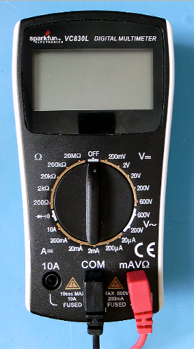
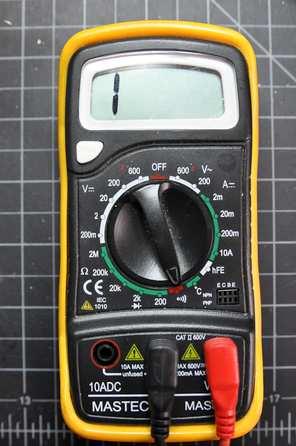
Figures 15 and 16 show two multimeters. Figure 16 is autoranging and Figure 15 is not. Notice how the autoranging meter has only one setting per function, while the non-autoranging meter has several per function. For example, Voltage on the meter in Figure 15 is divided into AC (marked by a ~) and DC (marked by a ⎓). Within those two areas, there are multiple possible ranges: DC voltage can be set to 200mV, 2V, 20V, 200V, or 6ooV. Each range setting represents the maximum voltage you can read on that setting.
Figure 15. A non-autoranging multimeter. Each function has multiple possible range settings.
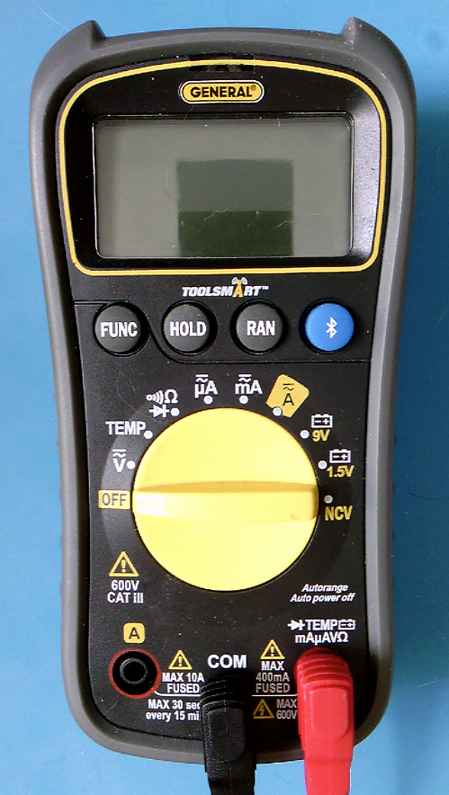
Figure 16. An autoranging multimeter. It has only one setting for each function and the meter automatically detects the range.
The Symbols on a Meter
Here are a few of the common symbols on electrical meters:
Volts: V
Ohms (resistance): Ω
Amps (current): A
AC: ~, ⏦ (tilde, sine wave)
DC: ⎓
Continuity: diode, speaker
Diode Check:diode
Non-Contact Voltage: NCV
Ground: ⏚ (vertical line with three horizontal lines below it)
Measuring Continuity
Continuity is simply whether or not there is a connection between two points. You just used this function to test your meter (Figure 17). Now you’ll use it to test a conductor.
Figure 17. This meter is ready to do a continuity check. The screen reads 1 on the right hand side. For this meter, this indicates that there is no continuity at the moment.
You can use the continuity check to find connections on a switch or if the pushbutton is connected when you press the button. You can also use it to measure whether there’s a break in a wire, or whether a given material conducts electricity. Set your meter as shown here, and try touching the probes together. The meter should beep.
Now try touching the probes to two ends of a wire. Again, the meter should beep. The wire conducts electricity. There is a continuous flow of electricity from one end of the wire to another.
Touching Two Points on a Switch
If you touch two points on a switch, what happens when you switch the switch? Beep or no beep? When you close the switch, the meter should beep, indicating that there is continuity between the two probes of the meter. If the meter beeps whether the switch is open or closed, then those two points are always connected.
Probing Points on a Breadboard
Put a wire in one hole of a breadboard that has no circuit on it. Then put another wire in another hole, chosen at random. Measure continuity between the two wires. Did you get what you expected? If the two holes were in the same row (or in the same column, on the side of the board) then you would get continuity and the meter would beep. If they were in different rows, then it would not beep.
Measuring Continuity Across Your Hand
Try measuring the continuity across your hand. Do you get anything? Why or why not? You probably don’t because the resistance across your skin is so high that it doesn’t register as a continuous conductor. It can conduct small amounts of current though. You don’t want your body to carry high amounts of current or voltage though, because it can damage or kill you.
Setup the Breadboard
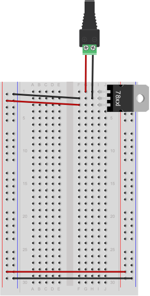
For the rest of this lab, you’ll need a breadboard connected to a +5 Volt or +3.3 volt power supply. You can use an Arduino as your power supply (Using Arduino Uno shown in Figure 18, using Arduino Nano shown in Figure 20), if it’s connected to a USB power supply or a DC power supply, or you can solder together a DC power jack as shown in the Soldering lab, and use a 9-12V DC power supply and a 7805 voltage regulator (Figure 19). The voltage regulator will take the DC power supply’s Voltage and regulate it down to 5 Volts DC.
If you are using a Nano for the first time, you might want to check out these videos before you get started, to prep your board and care for your microcontroller.
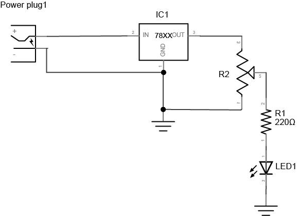
Note: Schematics
The diagrams to the left of some of the breadboard images in this exercise are called schematics.They show the electrical layout (as opposed to the physical layout) of the components. For a good rundown on reading and understanding schematics, see this page and some very useful videos on this topic in the videos section of this site.
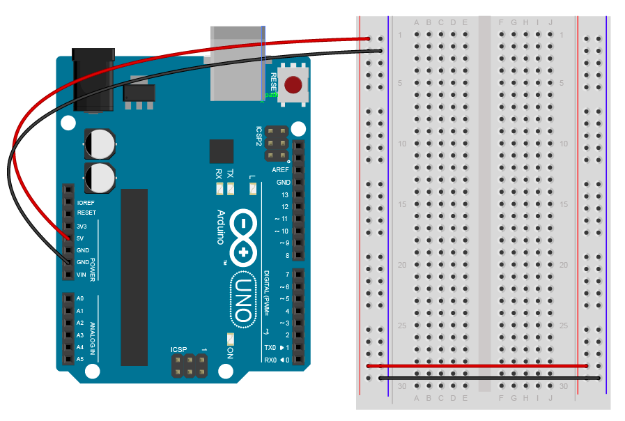
Figure 18. An Arduino Uno connected to a breadboard. The Arduino’s 5V and ground holes are supplying voltage to the breadboard.
Figure 19. DC voltage jack and 7805 voltage regulator on a breadboard. The regulator is supplying 5V and ground holes are supplying voltage to the rest of breadboard.
Figure 20. Breadboard view of an Arduino Nano connected to a breadboard.When plugged into a USB port, this board will supply 3.3V across the voltage and ground buses. The +3.3 volts and ground pins of the Arduino are connected by red and black wires, respectively, to the left side rows of the breadboard. +3.3 volts is connected to the left outer side row (the voltage bus) and ground is connected to the left inner side row (the ground bus). The side rows on the left are connected to the side rows on the right using red and black wires, respectively, creating a voltage bus and a ground bus on both sides of the board.
From here on out, diagrams will show the DC power supply and voltage regulator version, but feel free to use the Arduino version instead if you prefer.
Measuring Resistance of a Component
Resistance is a material property of any component, like a resistor or a wire. To measure the resistance of a component, you have to remove the component from the circuit. To measure resistance, turn your meter to the setting marked with the Greek letter Omega (Ω), as shown in Figure 21.
Figure 21. Multimeter set to measure resistance.
If your meter is not an auto-ranging meter, you want the meter set to the approximate range, and slightly higher than, of the component’s resistance. For example, to measure a 10-Kilohm resistance, you’d choose 20K, because 10K and 20K are in the same order of magnitude. For a 50K resistance, or anything over 20K, you’d have to step up to 200K. If you don’t know the component’s resistance, start with the meter set to a high reading, like 2M (2 Megohms). If you get a reading of zero, turn the meter one step lower, and keep doing so until you get a good reading. A reading of 1 on the left side of the meter, or of 0L, indicates you’re set to too low a range.
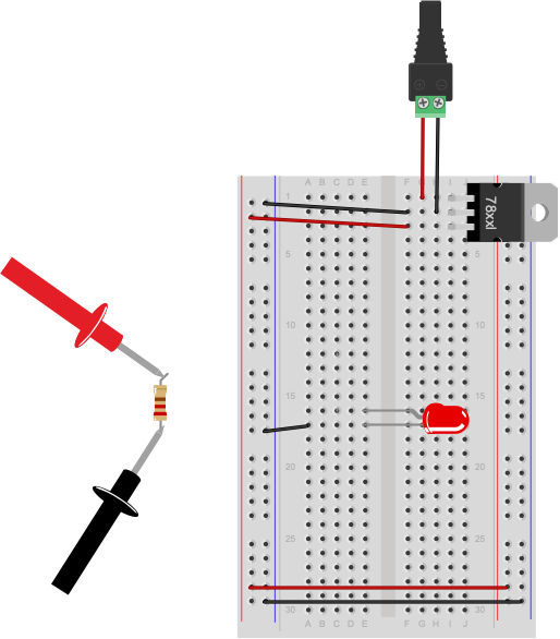
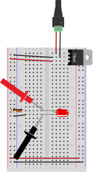
Figure 22. Measuring resistance. Note that this circuit is not complete. To measure a component’s resistance, you have to take it out of the circuit.
Not all components will register resistance. For example, a wire will ideally register 0 Ohms, because you want wires to have as little resistance as possible so they don’t affect the circuit. The longer the wire, the greater the resistance, however. Likewise, switches have ideally zero resistance.
The circuit shown in Figure 22 is not complete. The resistor connecting the LED to voltage has been removed to measure its resistance. The resistor would normally connect in the row connecting to the red wire (row 12) to the anode of the LED (row 15). To measure resistance of a component, you must remove it from the circuit.
Resistance and Diodes
If you measure the resistance of a diode (such as the LED shown in Figure 20), you may see a number flash briefly on the meter, then disappear. This is because diodes ideally have little or no resistance once voltage is flowing through them, but have what’s called a forward bias,which is a minimum voltage needed to get current flowing. Before you reach the forward bias voltage, the diode’s resistance is ideally infinite. After you reach it, the resistance is ideally zero. There are no ideals in electronics, however, which is why you see a resistance value flash briefly as the meter meets the diode’s forward bias. Most meters have a diode check setting, marked with a diode symbol, that will allow you to check the forward bias of the diode.
Try measuring the resistance across your hand. Set the meter really high, perhaps 20 Megohms. Do you get anything? You should get a resistance in the 2-20 Megohm range. Make your palm sweaty, or lick it, and try again. You should get a lower resistance, perhaps 0.2 Megohms or so.
Measuring Voltage
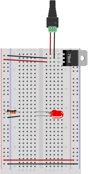
Once a circuit is complete and powered, you should learn to read voltages between different points in the circuit. Wire a 7805 5-Volt voltage regulator on a breadboard as shown above and connect it to power. If you don’t have one, you can use the 5V or 3.3V output from an Arduino instead, as explained above. Now add an LED and a 220-ohm resistor to the breadboard as shown in Figure 23.
Figure 23. Breadboard view of a 220-ohm resistor and an LED powered by a 5-volt regulator.
Note how the long leg, or anode, of the LED goes to voltage through the resistor, and the short leg, or cathode, goes to ground. Next you’re going to measure voltage in this circuit.
Voltage is a measure of the difference in electrical potential energy between two points in a circuit. It’s always measured between two points in a circuit. Measuring the voltage between the two sides of a component like an LED tells you how much voltage that component uses. When you’re measuring voltage between one side of a component and another, for example, it’s called measuring the voltage drop “across” the component.
Set your multimeter to measure DC volts (Figure 24). The voltage regulator you’re using can take an input voltage range of about 8 to 15 volts, and it outputs 5 volts, so you know that no voltage you’ll read in this circuit is over 15 volts. If your meter has a variety of ranges for DC volts, choose a range that ‘s closest to, and greater than, 15 volts. For example, many meters have a setting for 20 volts, meaning that they can read up to 20V DC at that setting.
Figure 24. Multimeter set to measure voltage. Note the horizontal and dashed lines indicating DC.
Measure for voltage between the power and ground bus rows on the breadboard. You should have 5 volts, or very close to that.
Now measure the voltage drop across the LED (Figure 25). When you’re measuring the voltage drop across a component, you put the meter probes in parallel with the component. In this case, the voltage across both the component and the meter will be the same.
Figure 25. Breadboard view of measuring voltage across an LED. The red lead is on the anode and the black lead is on the cathode of the LED.
Did you get a negative voltage? Why would that happen? That means you placed the red probe on the point of lower voltage, and the black probe on the point of higher voltage. In other words, you reversed the polarity.
A Switched LED Circuit
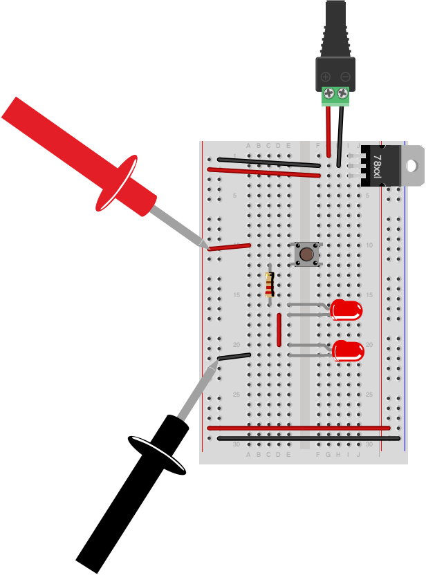
Now you’re going to make a more complex circuit. Disconnect the board from power and add a switch in series with the LED and resistor as shown in Figure 26 and 27. Remember, long leg (anode) goes to voltage, short leg (cathode) goes to ground).
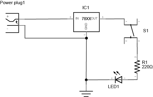
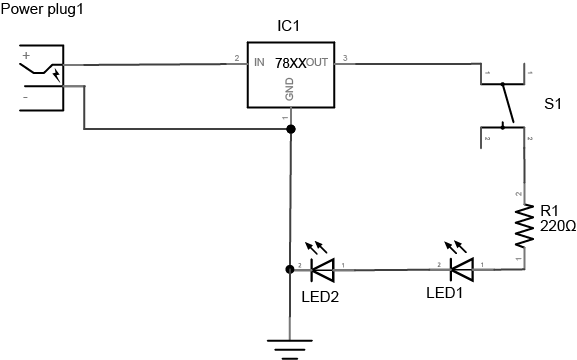
Figure 26. Schematic view of a pushbutton controlling an LED. A DC power supply of 8-12V is connected to the input and ground of a 7805 5V voltage regulator. The output of the regulator is connected to a pushbutton. The other side of the pushbutton is connected to one side of a 220 ohm resistor. The other side of the resistor is connected to the anode of an LED. The cathode of the LED is connected to the voltage regulator’s ground connection.
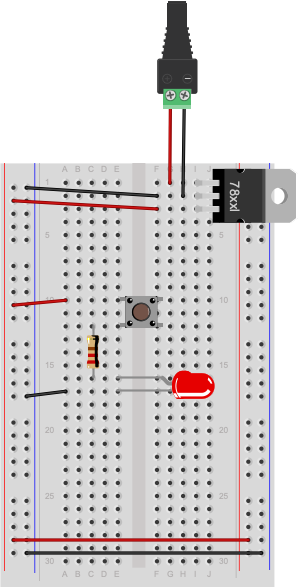
Figure 27. Breadboard view of a pushbutton controlling an LED. The components are connected as described in Figure 26.
Connect the board to your power supply and press the switch. It will illuminate the LED. Let go of the switch and it will turn the LED off again. By pressing the switch you are completing a circuit and allowing the resistor and LED to begin consuming electricity. The resistor is very important in this circuit as it protects the LED from being over-powered, which will eventually burn it out. A typical LED operates at a voltage of 2.0-2.6 volts (V) and consumes approximately 20 milliamps (mA). The resistor limits the current to a level that is safe for the LED. The higher the resistor value, the less voltage that will reach the LED. The lower the resistor value (with 0 ohms being no resistor at all), the more the voltage that will reach the LED.
Adding Up Voltage
Now, while playing with the pushbutton, measure the voltage across the pushbutton as you did in the last step, both in the on position and the off position. Is there a voltage drop across the pushbutton? What voltage do you read when the pushbutton is not pressed?
Measure the voltage across the LED and the resistor as well. Does the total voltage across all the components add up to the voltage between voltage and ground on your board? Remember, in any circuit, all of the voltage must be used up. Why? If the voltage across all the components doesn’t add up, that indicates to you that some of the electrical energy is getting converted to light, heat, and other forms of energy. No component is 100% efficient, so there’s always the possibility for some loss.
Components in Series
Change your circuit to add another LED in series with the first one, as shown in Figures 28 and 29.
Figure 28. Schematic view of a pushbutton controlling two LEDs. This circuit is similar to the one in Figure 24, but there are two LEDs in series after the resistor. The cathode of the first LED connects to the anode of the second, and the cathode of the second LED connects to the regulator’s ground.
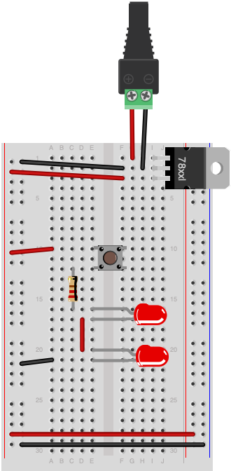
Figure 29. Breadboard view of a pushbutton controlling two LEDs. The components are wired as described in Figure 28.
Adding Up Voltage
Measure the voltage across the resistor, as shown in Figure 30. Then measure the voltage across each LED, as shown in Figures 31 and 32. Does the total add up to the voltage from power to ground? If not, where does the missing voltage go? The remaining energy is lost as heat generated from the components.
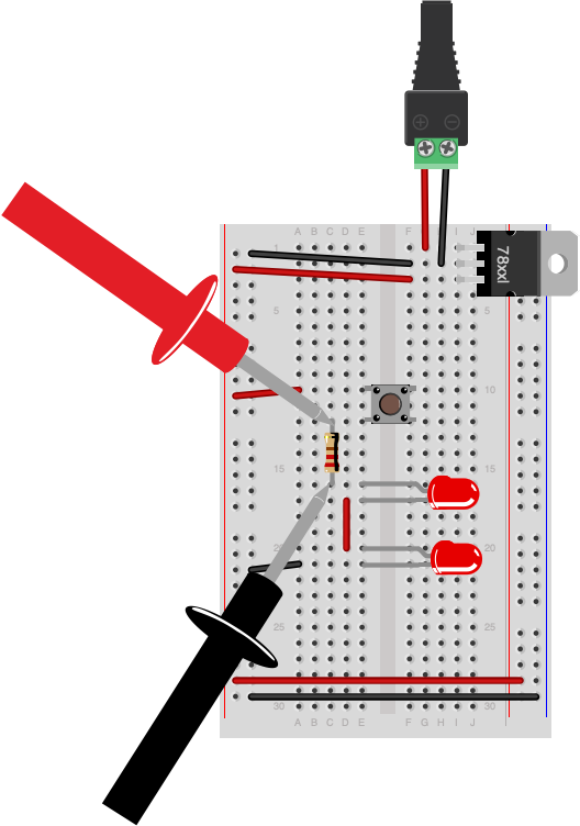
Figure 30. Measuring voltage across a resistor in a circuit. The circuit is wired as described in Figure 28. The meter’s leads are touching the two leads of the resistor.
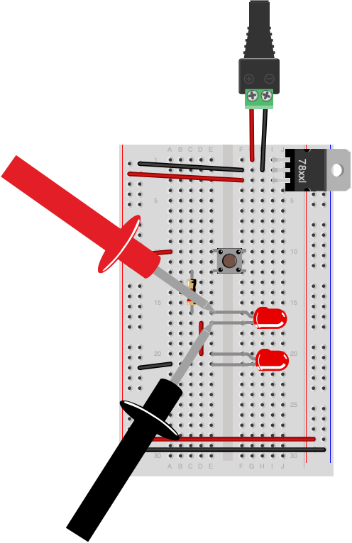
Figure 31. Measuring voltage across an LED in a circuit. The same circuit as Figure 28. The meter’s leads are touching the anode and cathode of the first LED.
Figure 32. Measuring voltage across a whole circuit. The same circuit as Figure 28. The meter’s leads are touching the power and ground buses.
Did you use two different color LEDs and get a different voltage drop across each one? That’s normal. Different color LEDs are made with different elements, and have slightly different voltage drops. Did you get no reading when you measured? Did you remember to push the button before you took your reading?
Adding a Third LED in Series
Add a third LED in series with the other two. Do the LEDs light? Why or why not? They most likely will not light up. Each LED needs about 2V to reach its forward bias and turn on. If you have three in series, and a 5-volt supply, each is getting less than the 2V it needs to turn on.
Components in Parallel/Measuring Amperage
Connect three LEDs in parallel as shown in Figure 33 and 34 (remember, long leg (anode) goes to voltage, short leg (cathode) goes to ground):
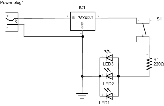
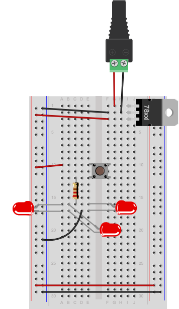
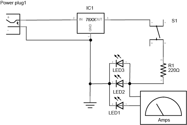
Figure 33. Schematic view of a pushbutton controlling three LEDs wired in parallel. The circuit is similar to Figure 26, but the two LEDs have been replaced by three LEDs which are all in parallel. The anodes of all three LEDs are connected to the resistor, and the cathodes are all connected to the regulator’s ground connection.
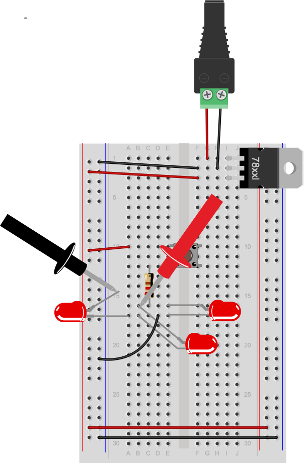
Figure 34. Breadboard view of a pushbutton controlling three LEDs wired in parallel. This circuit is wired as described in Figure 31.
Measure the voltage across each LED. It should be the same across each one.
Now you’re going to read the amperage at various points in the circuit. Move your meter’s red probe to the hole for measuring high amperage. On many meters, there are three holes, one marked “Volts/Ohms/mA”, and another marked “10A”. The right one can be used for measuring amperage when the expected amperage is less than 1A. The left is for measuring high amperage, up to 10A (Figure 35). If you’re not sure, it’s best to use the hole for 10A. Then set your meter to measure DC amperage.
Figure 35. Multimeter set to measure amperage up to 10A.
To measure the amperage through a given component, you need to place your meter in series with the component. When two components are in series, the amperage flowing through both of them is the same. For this, use the circuit with the three parallel LEDs that’s shown in Figures 36 and 37. To measure the amperage through any one of the LEDs in this circuit, you’ll need to disconnect one of the LED’s ends from the circuit (disconnect power first!) and use the meter to complete the circuit, as shown in Figures 36 and 37:
Figure 36. Schematic view of measuring amperage of one LED of three LEDs wired in parallel. This is the same circuit as shown in Figure 31, but the anode of one LED has been disconnected and then connected to one lead of a meter measuring amps. The other lead of the meter is connected to the junction between the resistor and the anodes of the other two LEDs.
Figure 37. Breadboard view measuring amperage of one LED of three LEDs wired in parallel. This circuit is wired as shown in Figure 34.
You’ll find that the amperage drawn by the LEDs is tiny, on the order of 10 or 20 milliamps at the most. That’s normal for LEDs. Make sure that you check which holes your meter probes are connected to when you’re using a meter.
Warning: Measuring amperage with the red probe in the voltage hole when you have no idea how big the current is, or measuring voltage with it in the amperage holes is a good way to damage the meter.
Generating a Variable Voltage with a Potentiometer
In this last step, you’ll generate a changing voltage using a potentiometer. A potentiometer is a resistor that can change its resistance. A potentiometer (or pot) has three connections. The outer connections are the ends of a fixed value resistor. The center connection connects to a wiper which slides along the fixed resistor. The resistance between the center connection and either of the outside connection changes as the pot’s knob is moved. Related video: Potentiometer schematic
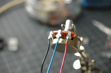
If your potentiometer does not have pins that will insert into a breadboard, then solder hook-up wires to the pot connections as shown in Figures 38 and 39.
Figure 38. A potentiometer with ring contacts, ready for soldering.
Figure 39. Potentiometer with wires successfully soldered.
Next, connect the pot to an LED and a 220-ohm resistor using the circuit shown in Figure 38:
Figure 40. Schematic view of a potentiometer controlling an LED. The two ends of a potentiometer are attached to the voltage output and ground of a 7805 voltage regulator. The middle contact of the potentiometer is connected to one end of a 220-ohm resistor. The other end of the resistor is connected to the anode of an LED. The cathode of the LED is connected to ground.
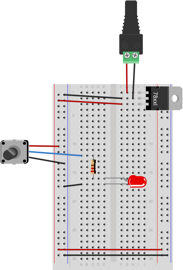
Figure 41. Breadboard view of a potentiometer controlling an LED. This circuit is wired as described in Figure 40.
As you turn the potentiometer from one end to the other, measure the voltage between the center position and ground. The pot is acting as a voltage divider, dividing the 5V into two parts. As the voltage feeding the LED goes up or down, the LED gets brighter or dimmer. The 220-ohm resistor in the circuit protects the LED from over-voltage when the resistance between the pot’s voltage lead and its center lead is 0 ohms.
Now you’ve got a basic understanding of how to use a meter to measure voltage, current, resistance, and electrical continuity. You’ll use these tests all the time.
In this lab you will learn about some of the components you’ll use frequently when making electronic circuits.
Introduction
In this lab you will learn about some of the components you’ll use frequently when making electronic circuits. For more on any given component, please check out its datasheet. There are no specific activities in this lab other than to examine the components and to familiarize yourself with them.
A datasheet or spec sheet is a document (printed or .pdf) that describes the technical characteristics of a sensor, electronic component, product, material or other. It includes details on how to use the component in a circuit and other useful design info on how to integrate it into a system together with specifications on performance and other characteristics that are important to know.
You’ll hear a few different terms for the parts you’re working with. A component is an electrical part that has a particular function, as described below. A component’s package refers to its physical form. The package is not dependent on what the actual part is. You’ll see a few components below that have the same package, like some of the voltage regulators and some of the transistors.
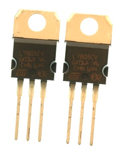
Different electronic circuits operate at different voltages. For example, the Arduino Uno operates at 5 volts, while the Arduino Nano 33 IoT and BLE, and the MKR series, operate at 3.3 volts. A voltage regulator takes a range of DC voltage as input and convert it to a constant voltage. For example, this regulator shown in Figure 1, a 7805 regulator, takes a range of 9 – 15 volts DC input and converts it to a constant 5-volt output. Using this regulator, you could power a 5-volt motor or a string of addressable LEDs from a 12-volt power source.
Note the label on the regulator that reads “7805”. This is the part number. Other parts have the same physical package, however. This is a TO-220 package. Many different parts use this same package, for example, and not all of them are voltage regulators. Also, sometimes the same part will come in different packages, so you can use it in different size devices.
The 7800 series regulators come in many different voltages. 7805 is a 5-volt regulator. 7809 is a 9-volt regulator. 7812 is a 12-volt regulator. All the regulators of this family have the same pin connections. In the image above, the left leg is connected to the input voltage. The middle leg is connected to ground. The right leg is the output voltage.
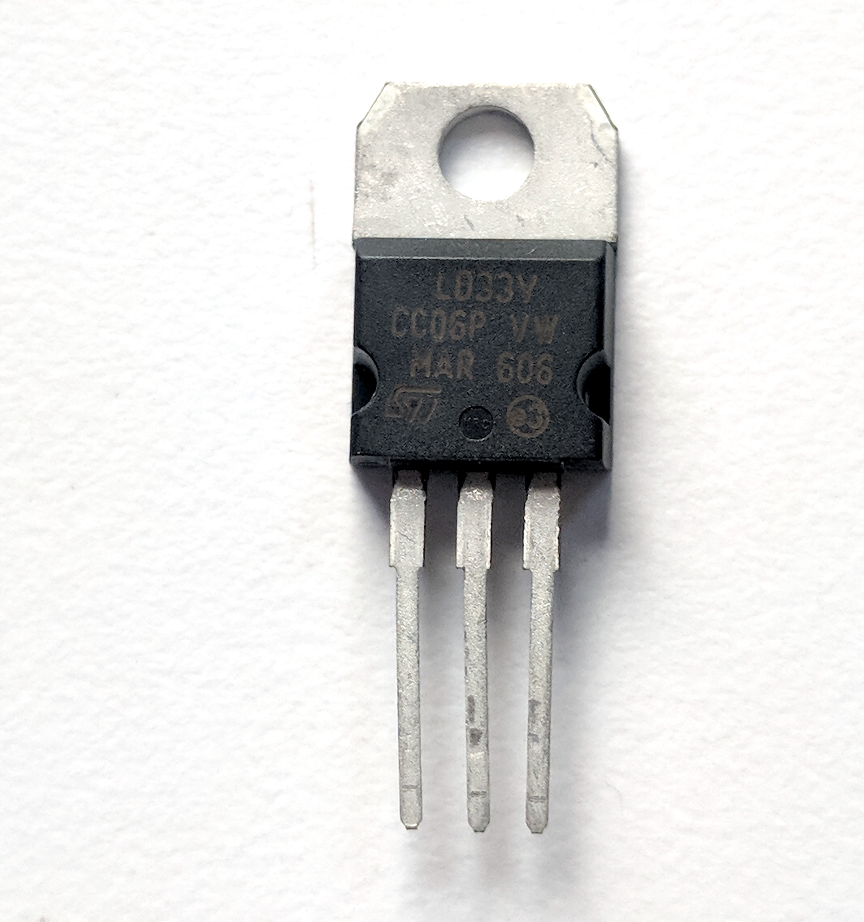
3.3V regulators are also common. Note that not all regulators which share the same package have the same pin configuration. For example, the LD1117V33, a 3.3V regulator shown in Figure 2, comes in the same physical package as a 7805, but its pins are in a different order. The LD1117V33’s pins, from left to right, are ground, output voltage, input voltage.
LED
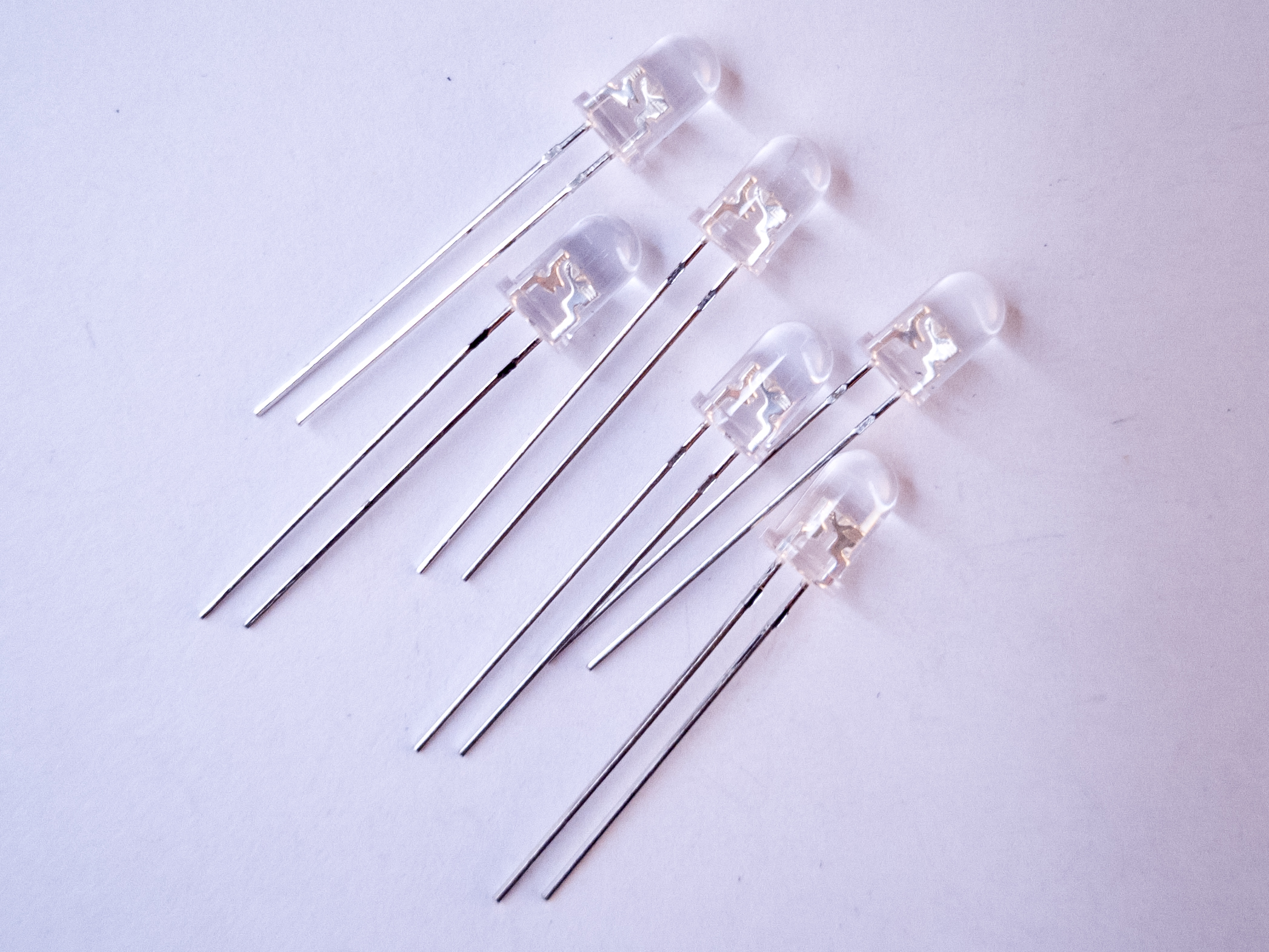
Figure 3. LEDs. Shown here are four LEDs. The one on the right is an RGB LED. You can tell this because it has four legs, while the others have only two legs.
LEDs, or Light Emitting Diodes (see Figure 3), are diodes that emit light when given the correct voltage and current. Like all diodes, they are polarized, meaning that they only operate when oriented correctly in the circuit. The anode of the LED connects to voltage, and the cathode connects to ground. The anode in the LEDs in this photo is the longer leg on each LED. LEDs come in many different packages. The packages above have built-in lenses.
These LEDs are the cheapest you can buy, and they’re not very bright. You can get super-bright LEDs as well, which are much brighter. If you’re working on applications that need very small light sources, you can also get LEDs in a surface mount package.
LEDs can only handle a limited amount of current and voltage. The details should be covered in each LED’s datasheet. Here is the datasheet of a typical white LED. You’ll see that the forward current is 30 mA max, and the forward voltage is between 2.9 and 3.6V. That means if you give it 30mA at 3.6V, you should get maximum brightness out of it. If you don’t have the datasheet for your LED, here’s a link to a handy LED current calculator. Try putting in the supply voltage (3.3V or 5V), the voltage drop across the LED (the forward voltage), and the current (30 mA) and see what value of resistance you get. For most common LEDs running at 3.3 or 5 volts, a resistor about 220 will limit the current safely while still providing enough to light the LED.
Solderless breadboards are reusable prototyping tools for electronics that allow you to build and experiment with circuits simply by plugging components in and out of its rows and columns. They come in different shape and sizes. Figure 4 shows a typical short solderless breadboard. It has two rows of holes on either side of the board, usually used as voltage and ground buses. The board is turned in this photo so that the bus rows are on top and bottom. In the center of the board, there are thirty rows of holes. There is a divider down the center of the board that breaks up the rows of holes into separate rows. There are five holes per row on the center left and on the center right of each row.
Resistors
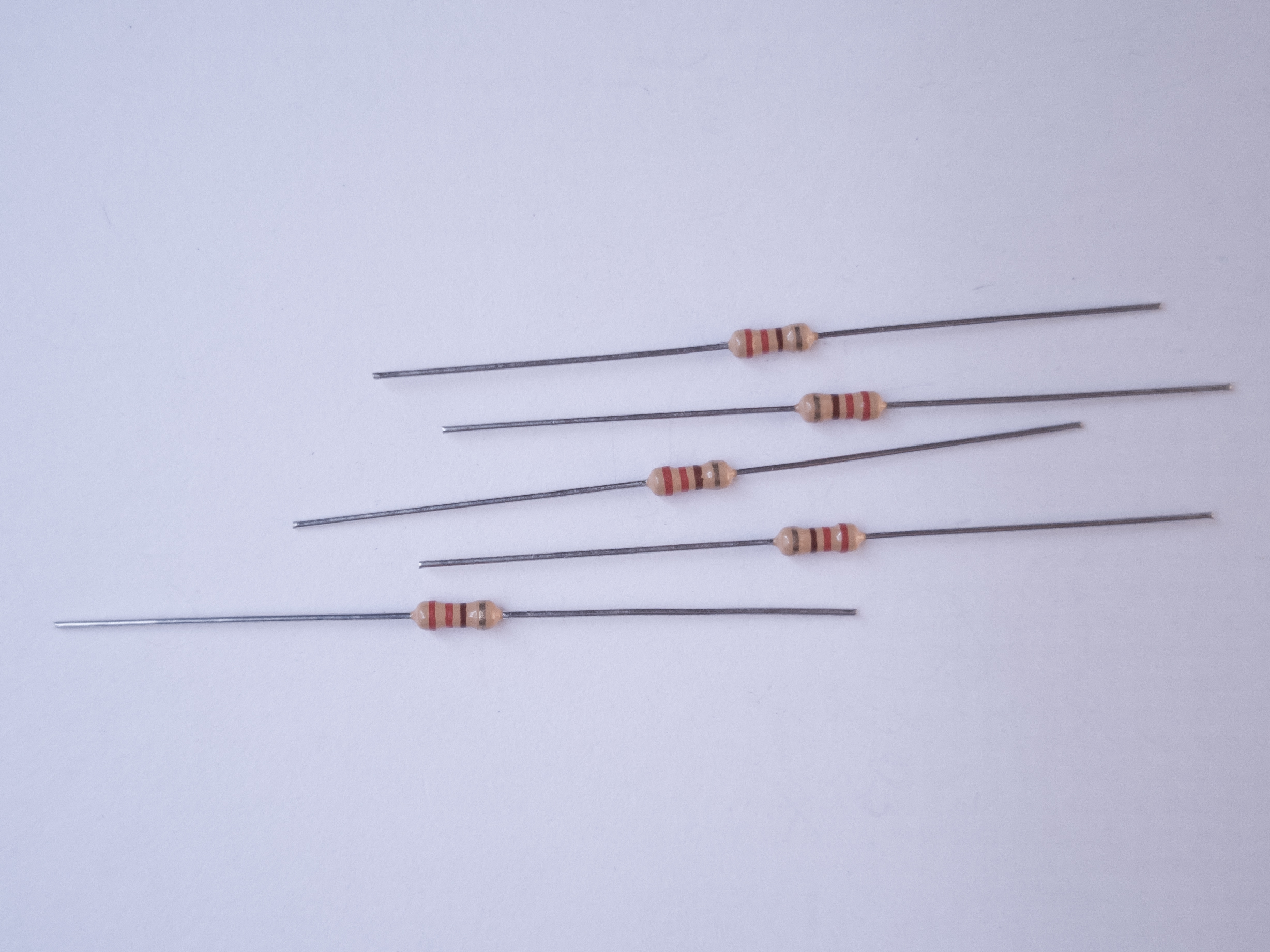
Figure 5. Resistors. Shown here are 220-ohm resistors. You can tell this because they have two red and one brown band, followed by a gold band.
Resistors resist the flow of electrical current. When placed in series, they reduce the voltage, and limit the current. The bands on a resistor indicate the resistor’s value. Here’s a handy resistor color code calculator. Resistors come in 4-band, 5-band, and 6-band models. In a 4-band resistor, the bands represent the first digit, second digit, multiplier, and tolerance. The resistors shown in Figure 5 are 4-band resistors marked red, red, brown, and gold, for 2, 2, times 101, 5%. In other words, these are 220 ohm resistors, +/-5%. The resistor color code calculator explains the bands for 5-and 6-band resistors as well.
Potentiometers
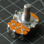
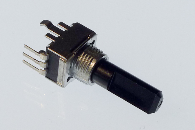
Figure 6. Potentiometer. The one shown here has three legs spaced 0.1 inches apart and can be therefore mounted on a solderless breadboard.
Potentiometers are variable resistors. The two outside terminals act as a fixed resistor. A movable contact called the wiper moves across the resistor, producing a variable resistance between the center terminal and either of the two sides. The potentiometer in Figure 6 has pins so you can mount it on a breadboard.
Trimmer potentiometers like those shown in Figure 7 are designed to be mounted on a circuit board, and are difficult to turn, so you can use them to adjust a circuit. They’re very small. They’re handy to use as physical variables, to tune your project.
Force Sensing Resistors
Force sensing resistors are sensors that change their resistance in response to force. They’re usually used to make analog alternatives alternatives to buttons. They’re made of a substrate of resistive rubber between two layers of conductive ink on a plastic film. They come in a variety of form factors. Figure 8 shows a pair of force sensors about 2.5cm across, sized for finger presses. There are a few companies who make them, including Interlink, Ohmite, and Tekscan.
Figure 8. Force sensing resistors
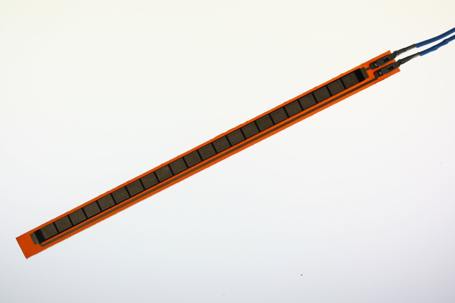
Flex Sensors (Flex Resistors)
Flex sensors are similar to force sensing resistors in construction, but they change their resistance as they bend. They are typically about the length of a finger, and they work well for measuring the bend of a finger. Spectrasymbol make these.
Figure 9. Flex sensor
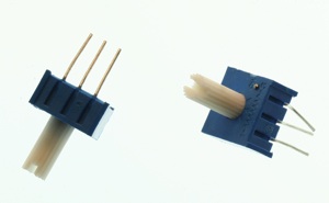
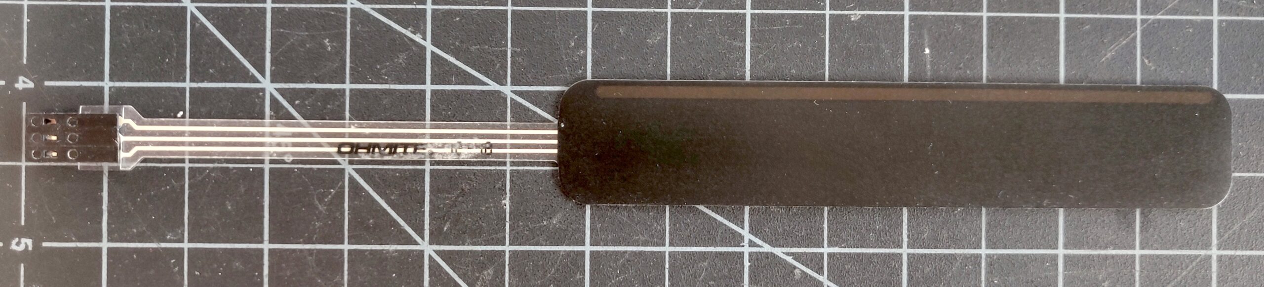
Force Sensing Potentiometers
Force Sensing Potentiometers, sometimes called SoftPots, are also similar to force sensing resistors. The difference is that a force sensing resistor gives one value wherever you press on it, while a force sensing potentiometer acts like a normal potentiometer: the value changes depending on where along its length you press. They come in linear and round form factors. Ohmite, Interlink, and Spectrasymbol make FSPs.
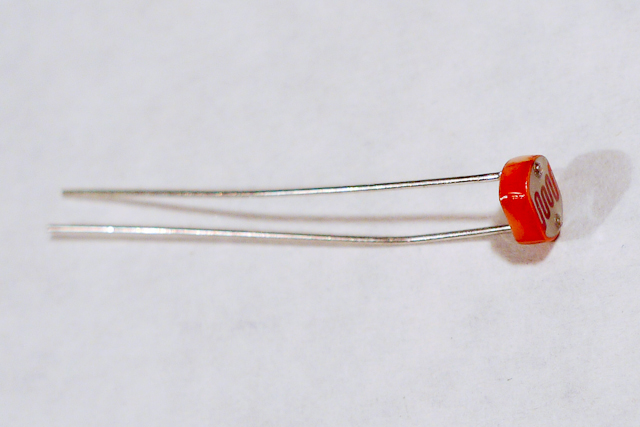
Light-dependent resistors, or photocells, are variable resistors whose resistance changes with the intensity of the light falling on the resistor. Photocells, as seen in Figure 11, are made with cadmium sulfide, which is a toxic chemical. Increasingly, they are being replaced in hobbyist kits by phototransistors, which are somewhat less toxic (see below).
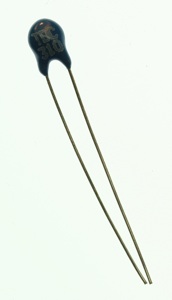
Thermistors
Figure 12. Themistor, or temperature-sensitive resistor
Thermistors, seen in Figure 12, are variable resistors whose resistance changes as the temperature changes. You measure the resistance between the two legs of the thermistor and expose the top to a varying temperature in order to vary the resistance between the two legs.
Switches
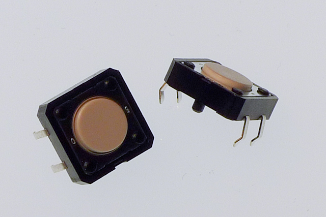
Figure 13. Pushbuttons, also called momentary switches
Switches are one form of digital input. There are many kinds of switches. The two most useful categories are momentary switches, which remain closed only when you press them, and toggle switches, which stay in place after you switch them.
Pushbuttons are a common type of momentary switch. The pushbuttons in the photo in Figure 13 above are designed to be mounted on a circuit board. They are very small, less than 1 centimeter on a side. They have four pins. When the button is facing you, top two are connected to each other, and the bottom two are connected to each other. Pushing the button connects the top pins to the bottom pins.
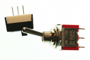
Toggle switches (Figure 14) stay in one position when you flip them. Wall light switches are common examples of toggle switches. Unlike a momentary switch, a toggle switch can be used to turn a device on or off, because they stay in one state when you remove your hand. The toggle switches below each have three connectors, also called pins or legs. They’re usually labeled C for common, NO for Normally Open, and NC for Normally Closed. When you switch the switch, it will open the connection between the common pin and the normally closed pin, and close the connection between the common pin and the normally open pin. Switch it the other way, and you will reverse the connection.
Figure 14. Toggle switches
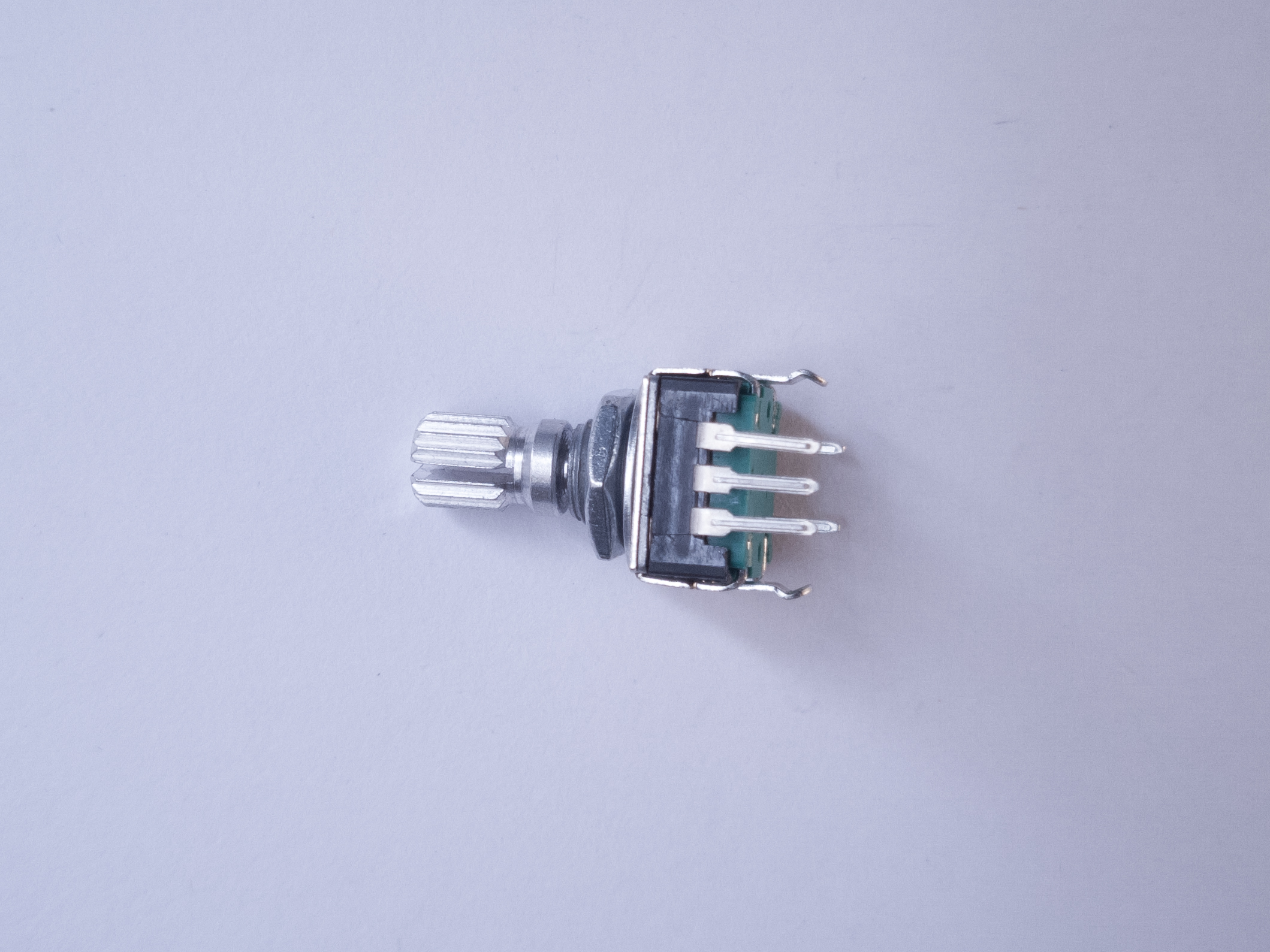
Rotary Encoder
Figure 15. Rotary encoder
A rotary encoder is a sensor that usually looks a bit like a potentiometer. It has a central shaft that you can turn with your fingers, or with an axle. It produces a pair of electrical pulses as you turn the shaft of the encoder, one slightly before or after the other, depending on the direction you are turning the shaft. Unlike a potentiometer, they can turn endlessly. They are used both as tangible controls, when you want a knob that turns endlessly, and as rotary sensors for motors and axles. The encoder in Figure 15 has three pins. The center is connected to ground, and the two side pins produce the pulses. The Encoder library for Arduino is useful for reading these.
Capacitors store electrical energy while there’s energy coming in, and release it when the incoming energy stops. They have a variety of uses. One common use is to smooth out the dips and spikes in an electrical supply. This use is called decoupling.
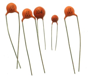
Ceramic capacitors are unpolarized. They generally have very small capacitance values. They’re useful decoupling caps in a low-current circuit. You often see them used to decouple the power going into a microcontroller or other integrated circuit.
The number on a ceramic cap gives you its value and order of magnitude. For example, 104 on the capactors in Figure 16 indicates a 0.1 microfarad (uF) cap. 103 indicates a 0.01 microfarad cap.
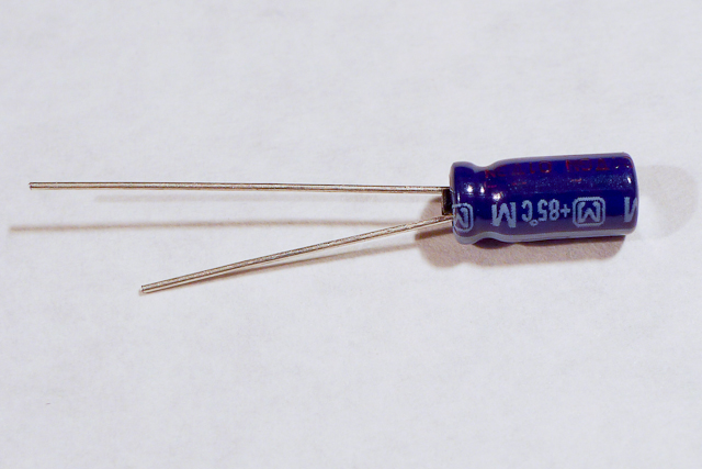
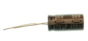
Figure 17. Electrolytic capacitor
Electrolytic capacitors (Figure 17) can generally store more charge than ceramic caps, and are longer lasting. They’re usually polarized, meaning that they have a positive leg and a negative leg. This is because current flows more efficiently through them one way than the other.
Figure 18. Electrolytic capacitor, showing the minus sign on the negative side.
An electrolytic cap will have a + or – on one side, as shown in Figure 18.
Diodes
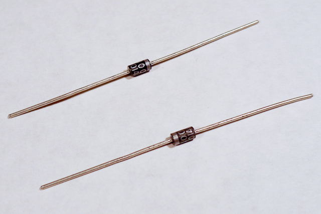
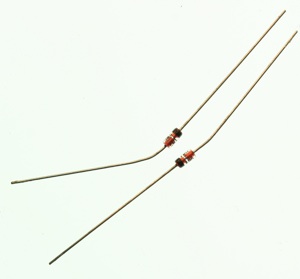
Figure 19. Diodes. Shown here are 1N400x power diodes. The body of the component is black, and the end is silver. The silver end indicates the cathode end of the diode.
Diodes permit voltage to flow in one direction and block it in the other direction. LEDs are a type of diode, as are the 1N4001 diodes shown in Figure 19. They’re useful for stopping voltage from going somewhere you don’t want it to go. The 1N4001 diodes are power diodes, capable of carrying a higher amount of current than other diodes.
Figure 20. Zener Diodes
Zener diodes (Figure 20) have a breakdown voltage past which they allow current to flow in both directions. They’re used to chop off excess voltage from a part of a circuit. They are usually smaller than power diodes.
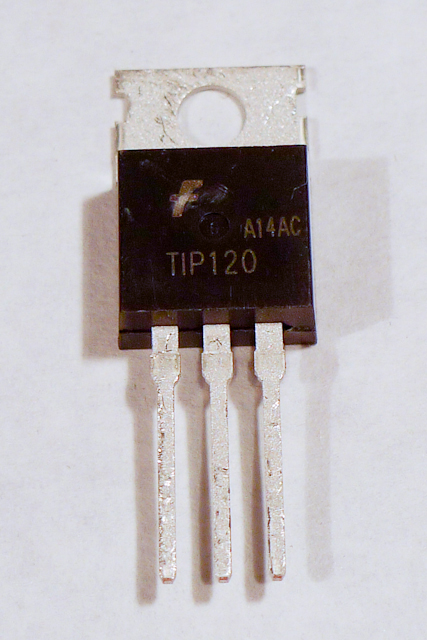
Transistors act as electronic switches. When you put a small voltage across the base and emitter, the transistor allows a larger current and voltage to flow from the collector to the emitter. The transistor shown above in Figure 21, a TIP120, is a type of transistor known as a Darlington transistor. It is usually used to control high-current loads like motors. Note that it uses the same physical form factor, or package, as the voltage regulator above (the TO-220 package).
The TIP120 shown here is jus one option for controlling high current loads. Metal Oxide Semiconductor Field Effect Transistors, or MOSFETS, are also good for controlling motors, lights, and other high current loads. These two models also come in the same physical package as the TIP120. The IRF510 and IRF520 MOSFETs have the same pin configuration as the TIP120, and perform similarly with a 5V gate voltage. The FQP30N06L MOSFET has the same pin configuration, and operates on as low as 1.0V, and works well for 3.3V applications. MOSFETs can generally handle more amperage and voltage, but are more sensitive to static electricity damage.
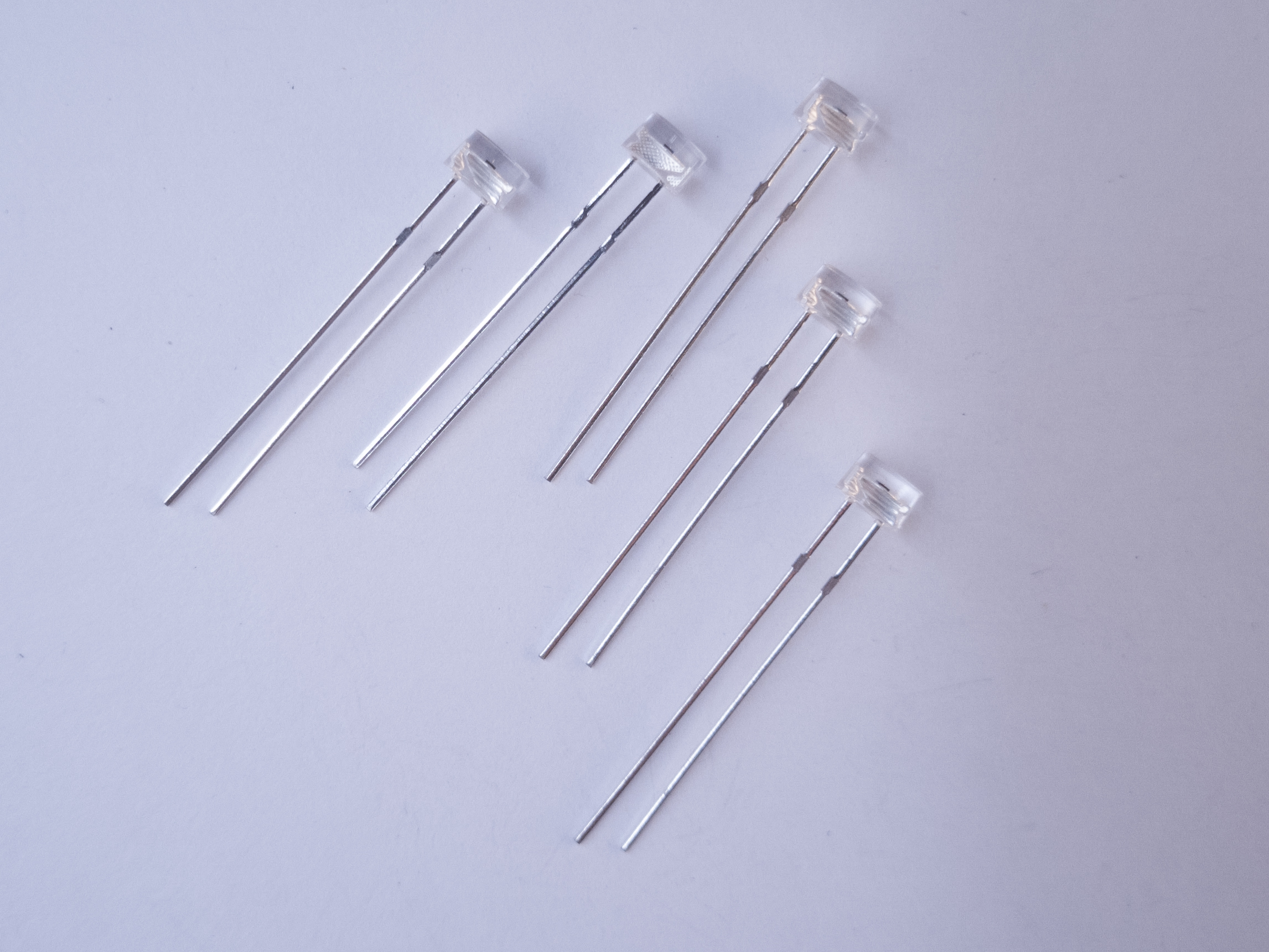
Figure 15. Phototransistors. The short leg goes to voltage, and the long leg goes to the input pin of a microcontroller.
Phototransistors are transistors, but instead of being controlled by electricity, they are controlled by light. The base of a phototransistor is photosensitive. They often look like LEDs. The ones in Figure 15, Everlight model ALS-PT243-3C/L177, have flat tops to differentiate them from LEDs. The short leg of a phototransistor is the emitter, and the long leg is the collector. The lens is the base. To use them in an analog input circuit. emitter goes to voltage and the collector goes to your input pin. A 10-kilohm pulldown resistor connects the input pin to ground, just as it would if you were using a photocell..
Power Jacks
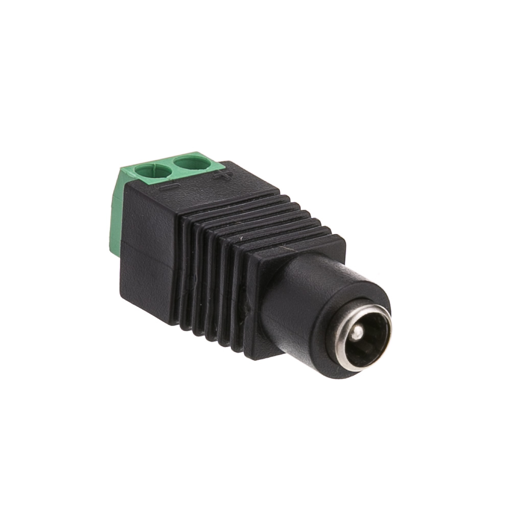
Figure 22. A DC Power Jack
DC Power jacks are used to connect your breadboard to a DC power supply that you can plug into a wall. They’re less common in microcontroller circuits now that USB power connectors and USB wall plugs are common, but they are still very handy when you have only a DC power supply to work with. The one in Figure 22 has screw terminals on the back to which you can connect wires to connect to your breadboard. It is a 2.1mm inside diameter, 5.5mm outside diameter jack, which is a very common size.
Battery Holders
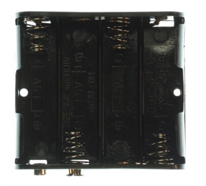
Figure 23. AA battery holder
Figure 24. 9V battery snap with DC power plug on it.
Battery connectors like the ones shown in Figures 23 and 24 are good for connecting batteries to your project. The one in Figure 20 can hold 4 AA batteries, and has a 9V battery snap on the outside. The one in Figure 21 has a DC power jack on one end, and a 9V battery snap on the other end.
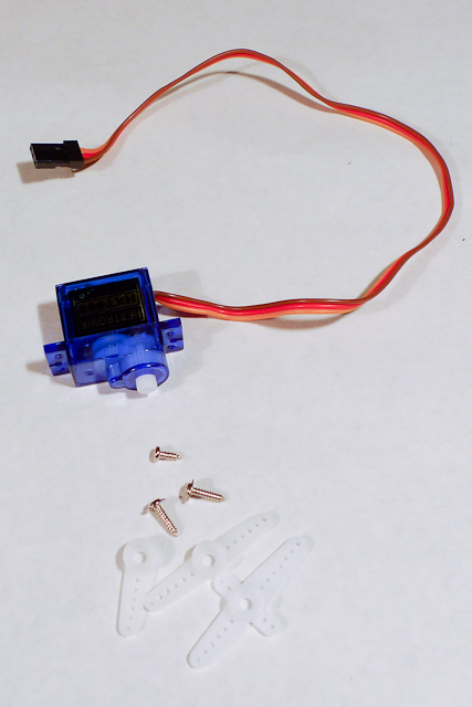
A servo motor is a motor paired with an encoder (e.g. a potentiometer) to provide position/speed readings and control messages in a feedback loop. This loop is used to precisely control of the servo’s degree of rotation. RC servomotors like the one shown in Figure 25 can only turn 180 degrees. They are often used for the rudder control on remote control planes and cars. The plastic bits shown in the photo are called horns, and they attach to the shaft to let you attach the motor to the mechanism that you want to control.
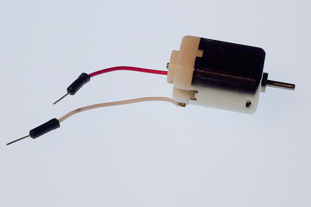
DC motors, as seen in Figure 26, utilize induction (an electromagnetic field generated by current flowing through a wire coil) to rotate a central shaft. You can reverse the direction that the shaft rotates by reversing the leads powering it.
Motor Driver
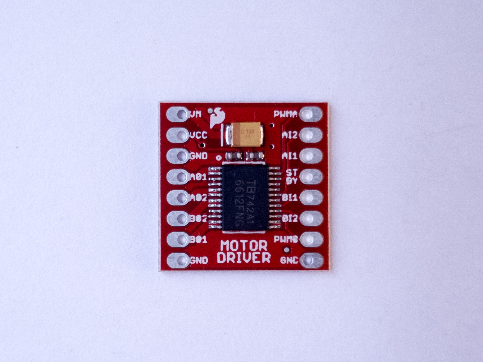
Figure 27. Motor Driver (H-bridge), model TB6612FNG
A motor driver, sometimes called an H bridge, is an electronic circuit that enables a voltage to be applied across a load in either direction. They are often used to control the direction of DC motors. The motor driver in Figure 27 is a Toshiba model TB6612FNG. It is a good option for both 5V (from an Arduino Uno) and 3.3V (from a Nano 33 IoT) control of DC motors and stepper motors.
Electromechanical Relay
Figure 28. Electromechanical relays: top and left views as well as inside.
Like transistors, relays are electronic switches. Electromechanical relays contain a small coil that, when energized, creates a magnetic field that moves a small metal armature to open or close an electrical contact. Relays can handle higher current than transistors and can be used for AC or DC loads. However, because they rely on a physical mechanism, they are slower and more prone to wearing out. If you want to control a relay with the Arduino, you will need to use a transistor as an intermediary because most relays draw more current than the Arduino’s output pins can supply.
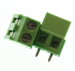
Screw terminals, as seen in Figure 29, are electrical connectors that hold wires in place with a clamping screw. They allow for a more secure connection than female headers and more flexibility than soldering a wire in place. There is one screw, socket, and pin per connection.
Sensor Modules
Increasingly, sensors are no longer just simple components that output a changing resistance or capacitance. Sensor modules are application-specific integrated circuits (ASICs) which read a particular physical property and give you a measurement via a synchronous serial communications channel like I2C.
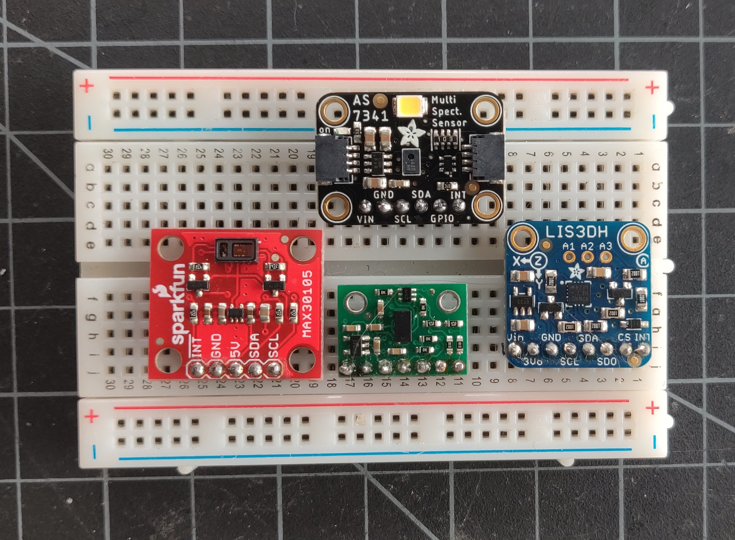
Figure 30 shows four different I2C sensors: a ten-channel spectrometer, at the top, which measures the intensity of light in ten different frequencies; An accelerometer, on the right (read below for more); a time-of-flight distance ranging sensor, that measures distance using an infrared low-power laser, on the bottom; and a light sensor that functions as both a particle sensor and a pulse oximeter, on the left, by measuring the change in color of your blood through the skin of your finger.
These are only a few of the many sensor modules available that can be connected to a microcontroller via I2C. You’ll see color and gesture sensors, temperature and humidity sensors, and many more. They are often available as breadboard-friendly breakout board modules, like the ones shown here, that are typically a circuit board that’s a few centimeters square, with holes on one side spaced 0.1″ apart so you can attach pins to plug it into a breadboard.
Figure 30. Various I2C sensors
Accelerometer
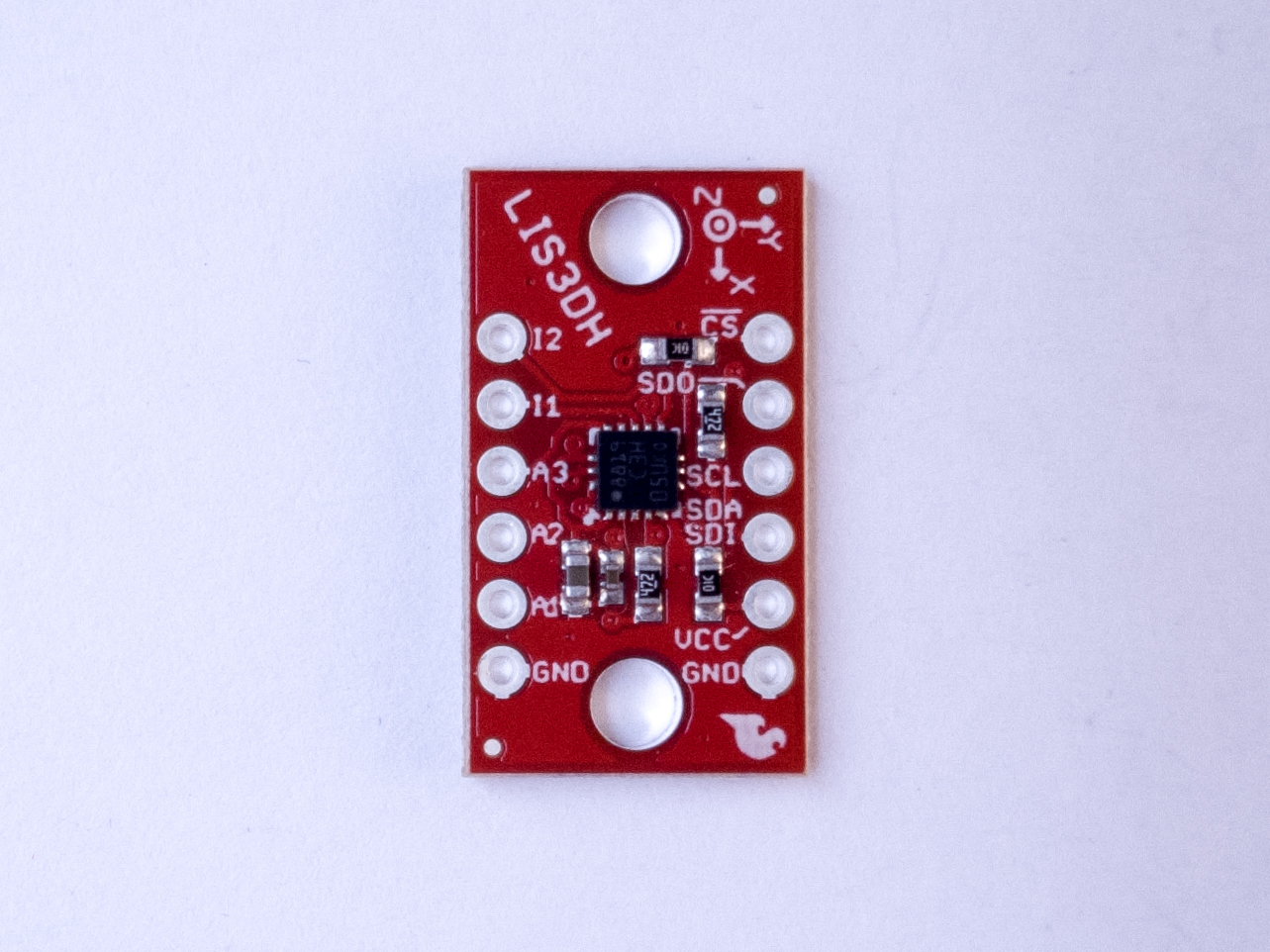
Figure 31. Accelerometer, LIS3DH
Accelerometers are sensors which measure a changing acceleration (Figure 31). They are typically part of sensors called Inertial Measurement Units, or IMUs. They are useful for measuring the tilt of a body, or for measuring the force of an impact. They come in both digital and analog forms. A typical accelerometer measures acceleration along three axes, all perpendicular to each other. Accelerometers are increasingly built into microcontroller modules and other electronic devices. There is accelerometer and a gyrometer built into the Nano 33 IoT.
Infrared Distance Ranger
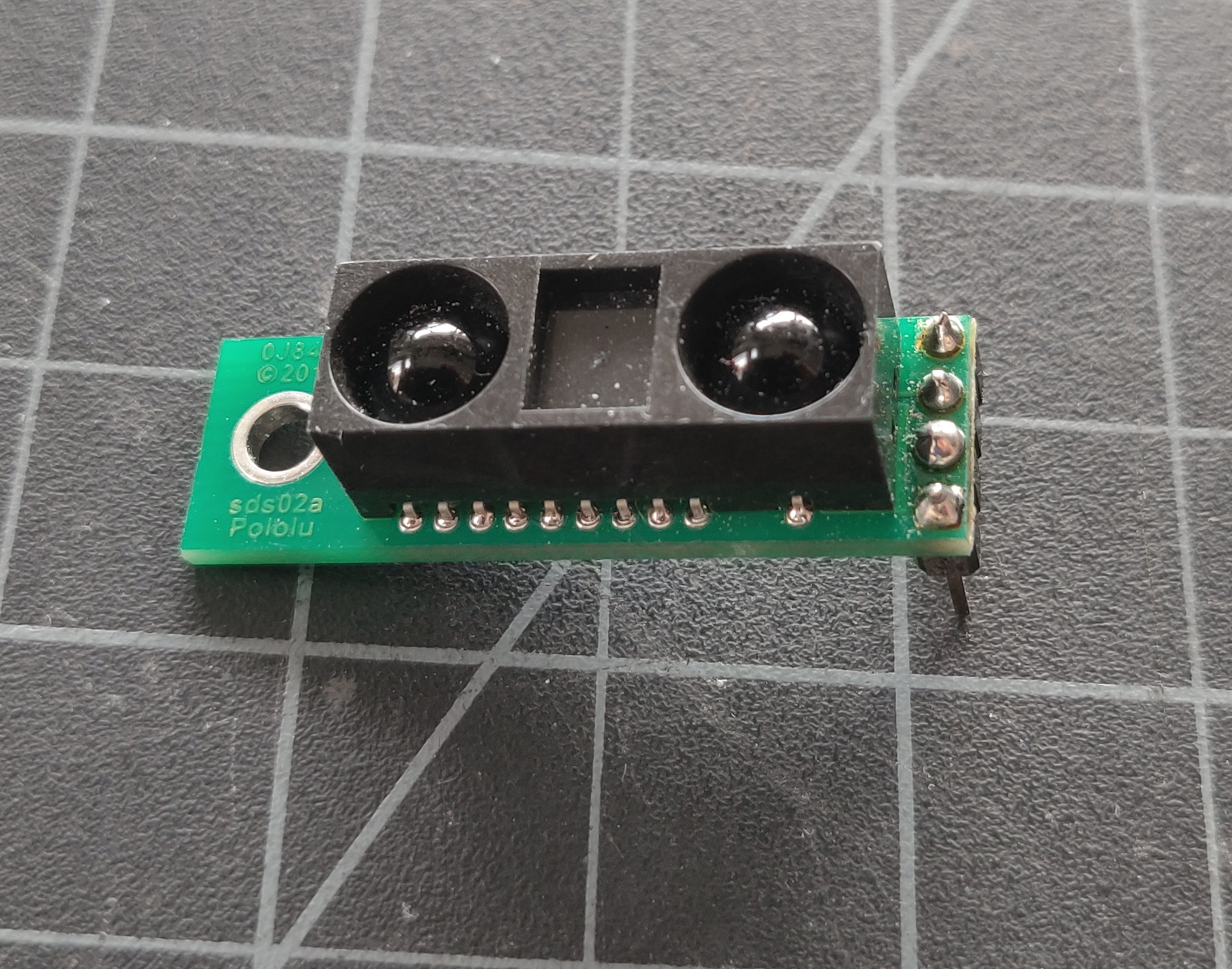
Sharp makes a line of infrared distance ranging sensors that measure distance in about a 1-meter range using infrared light. The one shown in Figure 32 has an analog voltage output.
Figure 32. IR distance ranger
Ultrasonic Distance Ranger
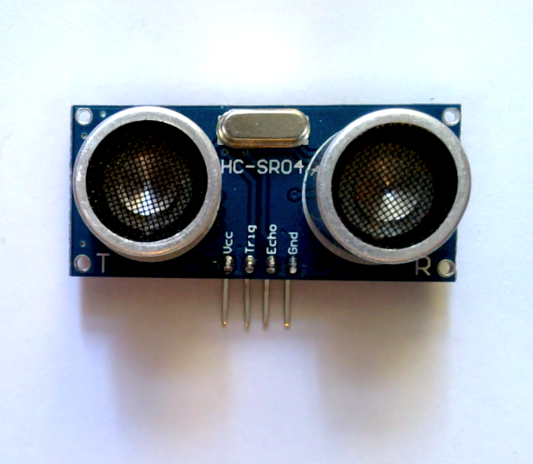
Ultrasonic distance rangers measure distance by emitting pulsed ultrasonic waves and listening for the echo from a distant object. These are sometimes used in cars to aid in detecting the distance of objects behind the rear bumper. The one shown in Figure 33 outputs a digital pulse whose pulse width varies with the distance from the target object.
Figure 33. An Ultrasonic sensor, model HC-SR04. The sensor has two cylindrical transducers, and four pins at the bottom of the board, labeled from left to right: Vcc, Trig., Echo, Ground.
Temperature and Humidity Sensors
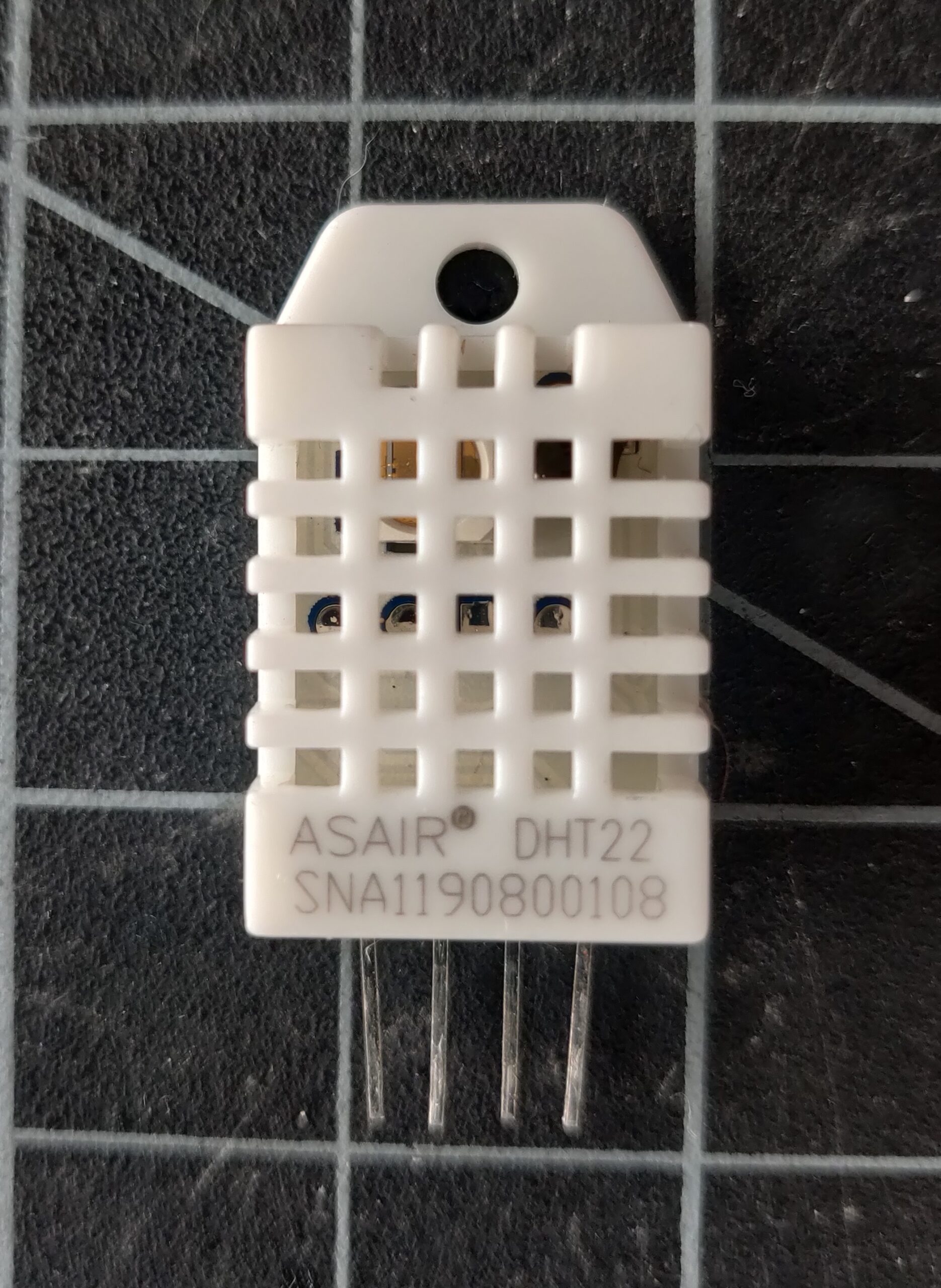
There are dozens of temperature and humidity sensors on the market, with many different interfaces. The one shown in Figure 34, the DHT22, is very popular because it’s simple to use, reliable with a long track record, and inexpensive. It uses a one-wire interface.
Figure 34. a DHT-22 temperature and humidity sensor
Speaker
Figure 35. Photo of an 8 ohm speaker
A speaker is a paper or plastic cone mounted to a coil of wire. The coil is mounted next to a magnet. When a current is passed through the wire, it induces a magnetic field, which attracts or repulses the magnet. This makes the cone vibrate, and produce sound. The speaker shown in Figure 35 is an 8-ohm speaker.