In this lab you’ll learn about converting voltage levels to make components communicate better.
In this lab you’ll learn about converting voltage levels to make components communicate better.
Introduction
Different microcontrollers and other digital devices operate on a range of different voltages. For many microcontrollers, 5V has been a common standard operating voltage for many years. Recently, however, new controllers are coming on the market that operate only at lower voltages. 3.3V has become common, and some controllers even operate as low as 1.7V. Just as microcontrollers are changing, the sensors and actuators that attach to them are changing as well. For example, many accelerometers on the market now operate at 3.3V instead of 5V. Because of this, you sometimes need to convert the output voltage of one device to match the input voltage of another. This is called level shifting. There are a number of ways to do it.
Most of the time that you need to shift voltage levels, you’re working with a voltage source that’s very low amperage, like a microcontroller’s I/O pins or the signal output from a sensor. Another common application is when you’re connecting a 5V microcontroller Like the Uno to a 3.3V board like the Raspberry Pi. You need to shift the Uno’s 5V signals to 3.3V for the Pi.
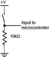
You know from the introductory electronics notes that two resistors in series can form a voltage divider (Figure 1). This is one way to reduce the voltage of a circuit. You need to calculate the ratio of the resistors based on the ratio of the input voltage to the output voltage. Here’s a handy calculator for working those values out. The tricky part about this is having the exact right resistors for the job. Also, resistors can slow down a high-speed signal because they have a built-in impedance, meaning that the voltage across them doesn’t change instantaneously. This can be a problem if you’re sending a high-speed serial signal, for example.
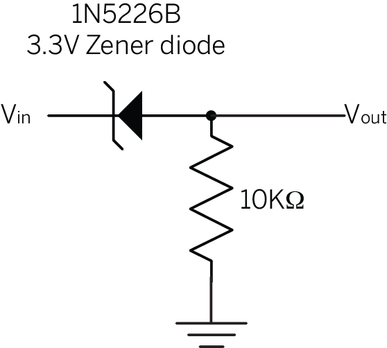
You can also use a zener diode to reduce the voltage. Zener diodes are diodes that allow current to flow from anode to cathode just like a regular diode, but also allows current to flow from cathode to anode up to a particular voltage, called the breakdown voltage. Zener diodes come in various breakdown voltages, so you can choose the one that works for your application. For example, the 1N5226 is a common 3.3V Zener diode, and the the 1N4733 is a common 5.1V Zener diode. When you’re using a Zener diode as a voltage shifter, you connect the cathode to the source, and the anode to the output, usually with a pulldown resistor as shown below in Figure 2.
Figure 2. This is a typical circuit for 5V-to-3.3V level shifting. If Vin is 5V, then V out will be 3.3V with this circuit.
Level Shifting With a Level Shifter IC
If you’ve got several of I/O pins to shift, then you can use a level shifter IC. These chips contain all the circuitry to shift from one level to another for you automatically. They are generally the most expensive solution, but the most reliable and convenient. Texas Instruments makes a series, the TXB010X family, that are popular in physical computing applications. The TXB chips can automatically detect the input and output levels and do the shifting for you. They come in 4-channel and 8-channel models, (TXB0104 and TXB0108) and both Sparkfun and Adafruit stock breakout boards for them. Texas Instruments has a detailed introduction to logic guide, and an application note for these chips as well. Many other manufacturers make level shifters; this family is just one convenient model. Figure 3 shows how you’d use a TXB0104 to connect an Uno to a Raspberry Pi.
Figure 3. Level shifting between an Arduino Uno and a Raspberry Pi using a TXB0108. Image made with Fritzing
The TXB101X level shifters have two voltage input pins, VccA and VccB VccB is the higher voltage input and VccA is the lower. You can see in the diagram above, VccA is connected to the Pi’s 3.3V out pin. Both devices are connected to the level shifter’s ground, so there is a common ground. Wired this way. the level shifter knows that all the A pins will be 3.3V and the B pins will be 5V, and it will convert between them. For more information, Sparkfun has a nice hookup guide for this chip. Note that their breakout board has a different pin arrangement than Adafruit’s, but operates in the same way.
In order to make two devices communicate, whether they are desktop computers, microcontrollers, or any other form of computer, you need a method of communication and an agreed-upon language. Serial communication is one of the most common forms of communication between computers. These notes explain the basics of getting two computers talking to each other using Asynchronous Serial communication.
Communicating serially involves sending a series of digital pulses back and forth between devices at a mutually agreed-upon rate. The sender sends pulses representing the data to be sent at the agreed-upon data rate, and the receiver listens for pulses at that same rate. This is what’s known as asynchronous serial communication. There isn’t a common clock in asynchronous serial communication; instead, both devices keep time independently, and either send or listen for new bits of data at an agreed-upon rate.
In order to communicate, the two devices need to agree on a few things:
the rate at which data is sent and read
the voltage levels representing a 1 or a 0 bit
the meaning of those voltage levels; is a high voltage 1 and a low voltage 0, or is the signal inverted so that a low voltage is a 1 and high voltage is 0?
For example, let’s say two devices are to exchange data at a rate of 9600 bits per second. First, you would make sure there’s an agreed upon high and low voltage supplying each device, then you’d make three connections between the two devices:
a common ground connection, so both devices have a common reference by which to measure voltage;
one wire for the sender to send data to the receiver on (transmit line for the sender);
one wire for the receiver to send date to the sender on (receive line for the sender).
Since the data rate is 9600 bits per second (sometimes called 9600 baud), the receiver will read the voltage on its receive wire every 1/9600th of a second. It will interpret that voltage reading as a new bit of data. If the voltage is high (typically +5V or +3.3V in the case of most microcontrollers), it will interpret that bit of data as a 1. If it is low (typically 0V), it will interpret that bit of data as a 0. By interpreting the bits of data over time, the receiver can get a detailed message from the sender. at 9600 baud, for example, 1200 bytes of data can be exchanged in one second.
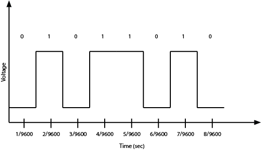
Let’s look at a byte of data being exchanged. Imagine you want to send the number ninety (90) from one device to another. First, you have to convert the number from the decimal representation, “90,” to a binary representation. In binary, ninety is 01011010. So your sending device will pulse its transmit line as shown in Figure 1:
Figure 1. Serial data transmission of 8 bits. The vertical axis shows the voltage of each bit, and the horizontal shows the time at which they bit is read. bits with the value 1 have a high voltage, and bits with the value 0 have a low voltage. [Tactile graphic available to download here.]
As you might guess from this diagram, both devices also have to agree on the order of the bits. Usually the sender sends the highest bit (or most significant bit) first in time, and the lowest (or least significant bit) last in time. As long as you have an agreed upon voltage, data rate, order of interpretation of bits, and agreement on what the voltage levels mean, you can exchange any data you want serially.
For the data transmission above, a high voltage indicates a bit value of 1, and a low voltage indicates a voltage of 0. This is known as true logic. Some serial protocols use inverted logic, meaning that a high voltage indicates a logic 0, and a low voltage indicates a logic 1. It’s important to know whether your protocol is true or inverted. For example, RS-232, which was the standard serial protocol for most personal computers before USB came along, uses inverted logic.
UART? USB? CDC?
The asynchronous serial communication you’ll be using here is sometimes referred to as TTL serial (transistor-transistor logic), and it’s not an inverted serial protocol. In TTL serial communications, high voltage means logic 1, and low voltage means logic 0. Most processors on the market today are equipped with one or more Universal Asynchronous Receiver-Transmitters, or UARTs, for communicating this way.
Most personal computers do not have an asynchronous serial port anymore. Instead, they have USB ports. USB stands for Universal Serial Bus, and it’s a slightly different serial protocol that allows multiple devices to communicate over the same wires. This configuration is known as a bus configuration. USB is a complex protocol that can support many different classes of devices, from human interface devices (HID) like mice and keyboards to mass storage devices to cameras, and more. Because so many devices still use asynchronous serial communication, USB includes a Communications Device Class (CDC) that supports asynchronous serial communication. Devices that include a USB-to-serial converter will show up as serial ports to your computer when you plug them in. Many microcontroller boards, including the Arduino boards, include a USB-to-serial converter to communicate with your computer in this way. When you plug them in, any program that can read serial ports will list the connected Arduino in the list of serial ports.
Some microcontroller boards, like the Arduino Uno, have a separate USB-to-serial chip on board, which allow them to appear as a USB serial device to your personal computers. Others, like the Arduino Nano 33 IoT, are USB-native, meaning that they can act as a USB device without a separate chip on board. These types of boards will appear to your personal computer as a USB serial device when their sketch is running, and will temporarily disappear when they reset. The advantage of a USB-native microcontroller is that they can also be programmed to behave as other USB devices, like MIDI, Mouse or Keyboard.
Serial Buffers and Control of the Port
Once you’ve got the computer and the microcontroller connected, you’ll need to write a program to address the serial ports. The process is slightly different on the different microcontrollers, but there are some elements common to all of them.
All processors that have a UART (this includes personal computers and microcontrollers, and most embedded boards like the Beaglebone Black and Raspberry Pi as well) have an area in memory where they store incoming data from the serial ports called a serial buffer. Because of this, they can do other tasks while waiting for data to come in, and act on the data from the buffer after it comes in.
Serial ports can only be controlled by one program at a time. For microcontrollers that aren’t running an operating system, this is simple; whatever program is running on the controller gets the serial port. On computers with an operating system, you might have multiple programs running, but only one can control a given serial port at any one time. For example, if you have a laptop connected serially to an Arduino, and the Arduino IDE’s Serial Monitor is open, then no other program can read from that serial port. You’d need to close the serial monitor to open the port from Processing or any other application. Related video: Only one program can control the port
Once you’ve got the serial port open, any bytes sent by the connected device will be available to your program in the order that they were sent. As you read each byte, the byte is removed from the serial buffer. This is why serial buffers are also called First-In, First-Out or FIFO buffers.
For more on sending serial from Arduino to another computer, see one of these labs, depending on the programming language you plan to communicate with:
When two devices are communicating serially, they can’t read each other’s program logic. They can only read what the other device has said. Because of this, you need to make sure that the programs on both sides are using the same communications protocol. This is the highest level of agreement in serial communications: both sides need to agree on what the bytes being sent mean, and in what order they are being sent. For more on this, see the serial data interpretation notes.
When you’re using microcontrollers, you frequently need to control devices that need more electrical current than a microcontroller can supply. Common examples include:
Controlling a DC motor
Controlling low-voltage (12-24V) lights
Controlling addressable LEDs
For all of these applications, you’ll need a high-current power supply. For some applications where the load operates at a voltage higher than your microcontroller but less than your power supply, you’ll need a voltage regulator and to set up your circuit to power the microcontroller and the load through it. For many of these applications, you’ll also need an electrical relay or transistor to control the load. These notes explain relays and transistors as they’re used for this purpose. In order to get the most out of these notes, you should know something about how electricity works, and you should know the basics of how a microcontroller works as well.
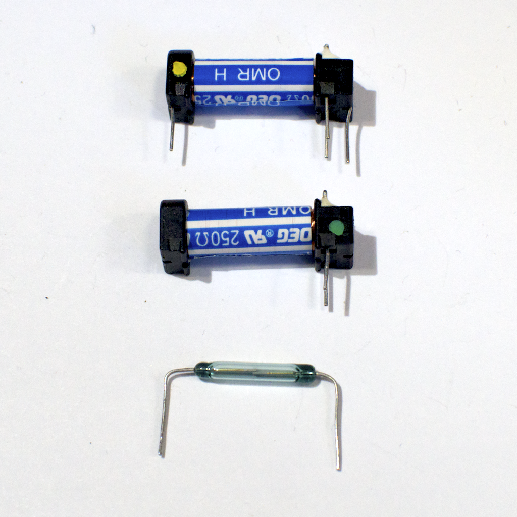
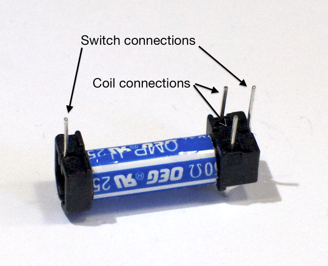
Digital output from a microcontroller is typically a low-amperage signal. For example, when you set a pin HIGH, the voltage coming on that pin is typically +3.3V or +5V, and the amperage that it can source is around 10 milliamps. This is fine if you’re controlling an LED, whose required amperage is tiny. However, most devices you’d want to control need more current than that to operate. You need a component in between your microcontroller and the device that can be controlled with this small voltage and amperage. Relays and transistors are most often used for this purpose. A relay is a switch that’s controlled by a small electric current. Relays take advantage of the fact that when you pass an electric current through a wire, a magnetic field is generated surrounding the wire as well. This is called induction. When you place two pieces of ferrous metal near a coil of wire and pass current through the wire, the magnetic field can move the two pieces of metal towards each other. Those pieces of metal can form a switch, which can be turned on and off by putting current through the coil, as shown in Figure 1, 2 and 3.
Figure 1. Two relays, one whole and the other with the switch removed. The blue and white tube in each relay is the coil, and the glass vial, which is normally inside the tube, contains the switch
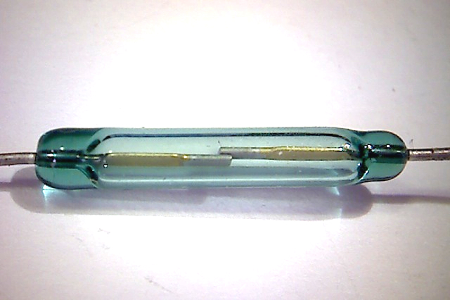
Figure 2. Detail of the switch inside the relay, magnified 20x
Figure 3. Relay connection pins In this image the four pins are visible. The two on the long end of the relay tube are the switch connections. The two pins on one end of the tube, on an axis perpendicular to the tube, are the coil connections.
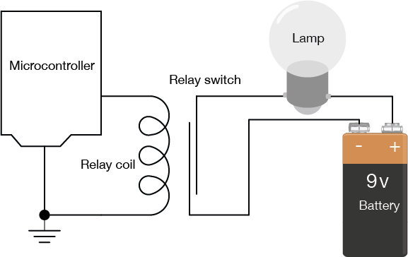
Figure 4. Diagram of Relay wired to a microcontroller and a lamp with a + 9 volt battery/ The switch terminals are connected to one terminal of a lamp and to the negative terminal of a 9V battery, respectively. The other terminal of the lamp is connected to the positive terminal of the battery. One of the coil terminals is connected to the output pin of a microcontroller, and the other is connected to the microcontroller’s ground. There is no electrical connection between the microcontroller circuit and the lamp circuit.
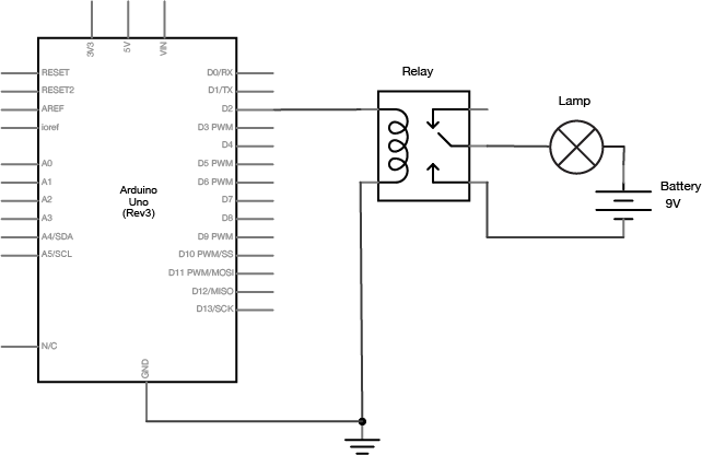
In Figure 4, you can see that there’s no electrical connection between the microcontroller circuit that’s controlling the coil of the relay and the lamp circuit. This is one advantage that relays offer. Figure 5, a schematic of the relay circuit is the same as Figure 4, but shown with traditional schematic symbols for the relay, the battery, and the lamp:
Figure 5. Schematic of a relay wired to an arduino and a lamp with a + 9 volt battery
The current needed to move the shaft in the coil is very low (less than 10 milliamps) so the coil can be energized by an output pin of your microcontroller. The current that can flow through the switch, however, is much higher. The lamp circuit is separate from the microcontroller. It uses a separate power source, with the amperage and voltage needed to turn on the lamp. The power source, the lamp, and the switch side of the relay are all placed in series. When the coil is energized, the leaves of the switch are physically moved by the magnetic force created, the lamp circuit is completed, and the lamp turns on.
Because there is no electrical connection between the switch and the coil, relays can also control AC loads as well as DC loads. You can’t use a relay to dim a lamp or control the speed of a motor, however. The switching speed of relays is too slow to pulsewidth modulate them.
Because a relay is a mechanical switch, it can be somewhat slow. Relays take a few milliseconds to close, so they aren’t very effective when you want to turn them on and off rapidly. Sometimes you need to switch a high current circuit rapidly. In this case you would use a switching transistor. A transistor is an electronic device that can work as a switch. It allows control of a large current by a smaller current as does a relay. Unlike a relay, however, a transistor is not mechanical, and can operate much faster than a relay. There are several types of transistors and they come in two major classes: bipolar transistors, and field-effect transistors, or FETs. All transistors have some similar properties though. They all have three connections, referred to as the base, the collector, and the emitter (on FET transistors, the three connections are the gate, the drain and the source).When you apply a small voltage and current between the base of a transistor and the emitter (or the gate and the drain on a FET), you allow a larger current to flow from the collector to the emitter (or the drain and the source).
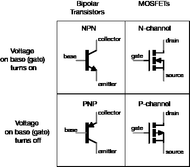
Among bipolar transistors, which are the older class of transistors, there are two types: NPN transistors, and PNP transistors. When you apply positive voltage to the base of an NPN transistor, it turns on the collector-emitter connection and allows current to flow from collector to emitter (Figure 6). The equivalent MOSFET is called an N-channel MOSFET. When you apply voltage to the base of a PNP transistor, by contrast, the collector-emitter connection turns off, and no current can flow from collector to emitter. The MOSFET equivalent is a P-channel MOSFET. One of the main differences between MOSFETS and bipolar transistors is that MOSFETS require negligible current on the base in order to activate. For the purposes of switching a load on and off, they are an excellent choice.
Figure 6. Chart comparing Bi-polar transistors and MOSFETS. NPN Transistors behave similarly to N-Channel MOSFETS. PNP Transistors are comparable to P-Channel MOSFETS
Among the bipolar transistors, there’s one type commonly used to switch high-current loads, the Darlington transistor. Darlington transistors are actually two transistors in one, combined with a diode that protects the transistors from damage in case the load’s current runs in reverse. In many of the labs on this site, you’ll see reference to one the TIP120 Darlington transistor.
Darlington transistors aren’t the only good transistors for high-current loads, though. You could use an N-Channel MOSFET with a protection diode in place of the darlington transistor. The IRF520 MOSFET is a good equivalent if you’re using a 5-volt microcontroller like the Uno. The FQP30N06L MOSFET works well for both 5V microcontrollers and 3.3V microcontrollers like the Nano 33 IoT.
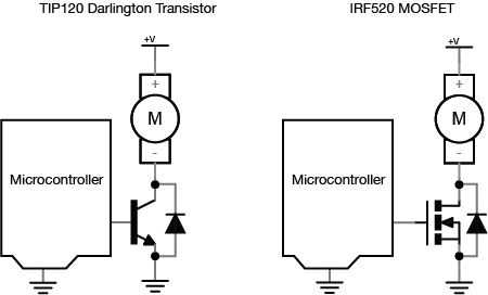
Figure 7 shows the basic circuit for using a transistor to control a high-current load. You connect a DC power source to one terminal of the load, then connect the second terminal of the load to the collector of the transistor (or drain, for a MOSFET) of the transistor. The emitter (or source) is then connected to ground, and the base (or gate) is connected to the output of your microcontroller. When you take the output pin of the microcontroller high, the voltage difference between the base (or gate) and the emitter (or source) allows current to flow through the load, through the collector (or drain) to the emitter (or source) and to ground.
Figure 7. Two similar microcontroller and motor schematics. The first schematic uses a Darlington Transistor. The second uses an N-Channel MOSFET.
Note how similar this schematic is to the relay schematic. The transistor here is serving the same function as the relay. However, it can switch much faster than the relay. In addition, because there are no mechanical parts, it will reliably function for more switching operations than the relay. However, current can only flow in one direction through a transistor. If the voltage on the collector (or drain) is lower than that on the emitter (or source), you can damage the transistor. The same is not true with a relay.
There are three differences between this transistor circuit and the relay circuit above. The first is that you’re using a motor as the load, rather than an incandescent light bulb. Because motors are inductive loads (they work because of induction; for more, see the DC motor notes), they can create a reverse voltage when spinning down after you turn them off. Because of this, the second difference is the protection diode in parallel with the transistor. The protection diode routes any reverse voltage around the transistor, thereby protecting it. Most transistors designed for controlling motors have a protection diode built-in. The TIP120, the IRF520, and the FQP30N06L all have built-in protection diodes. The third difference is that the microcontroller attached to the base (or gate) and the transistor’s emitter (or source) must have a common ground. If not, then the circuit will not work.
If you are switching DC motors, solenoids, or other high-current DC devices which create motion, it’s better to use a switching transistor than a relay. The ideal way to control a motor is with an H-bridge, which is an array of transistors that lets you control not only speed but also direction. There’s more on that in the motor control notes.
Sensors convert various forms of physical energy into electrical energy, allowing microcontrollers to read changes in the physical world.
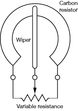
The simplest sensors read changes in mechanical energy, usually by moving electrical contacts. For example the pushbutton or switch (related video) converts mechanical energy (e.g, your finger’s press) into electrical energy by closing a connection between two metal contacts. The potentiometer (related video) shown in Figure 1 and Figure 2 is another sensor that reads mechanical energy changes: a metal contact called a wiper slides along a resistor, effectively short circuiting the resistor (related video) into two halves and creating a voltage divider circuit.
Figure 1. A potentiometer broken open, showing the carbon substrate and wiper.
Figure 2. Inside a potentiometer, the wiper, attached to the center contact, slides along the carbon resistor, forming effectively two resistors in series.
Although switches and pushbuttons typically only read an on state or an off state, most other sensors can read a wide range of possible states. In other words, they’re analog sensors, because they read a variable change. Whenever you use a new sensor, the first thing you need to understand is what the range is that it can read and deliver. When you’re using your sensor in an application, you need to know the range of possible values your application requires. Do you just need high, medium, and low (3 possible values), or a range from 0 to 10? Do you need a 100-point range? The range that you need depends on what your user can perceive. For example, if you’re making a lighting dimmer, and your user can only perceive about a dozen different light levels, then you don’t need to give her a sensor that can give her a 1000-point range of control.
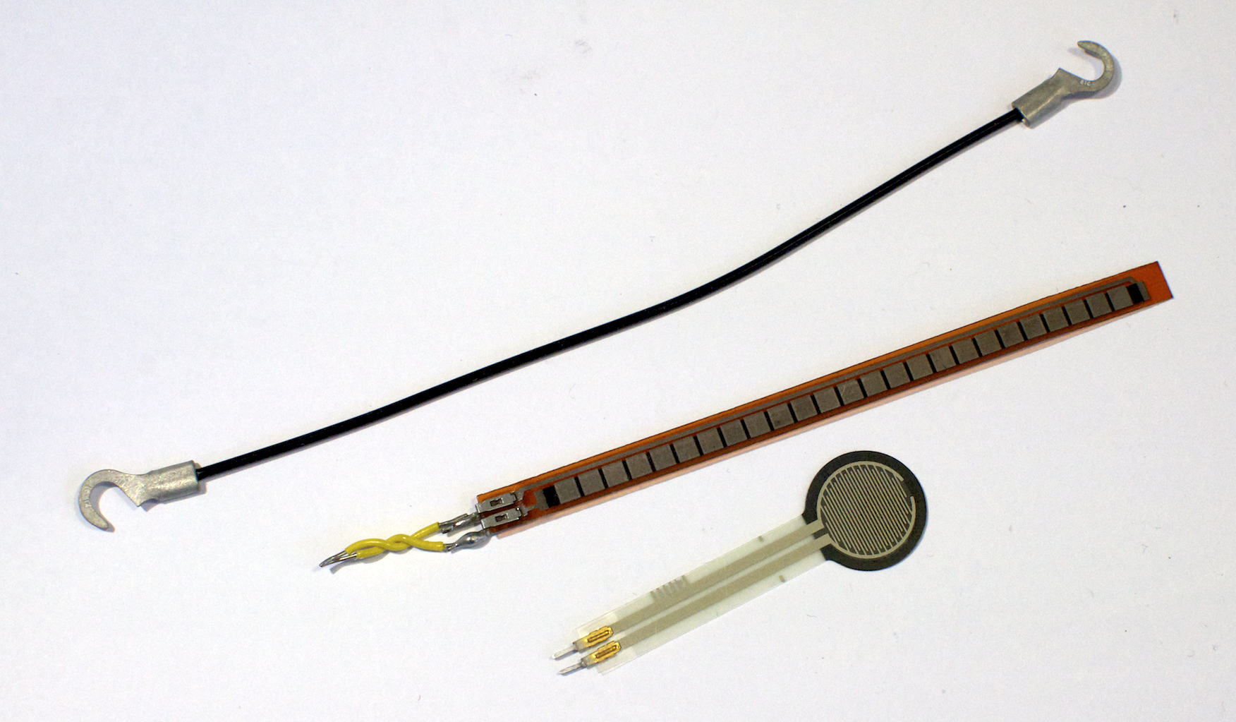
Many sensors work by converting the energy they read into a changing electrical resistance by using a variably resistive material at their heart. Examples of resistive sensors are shown in Figure 3. For example, force sensors and stretch sensors are made of a partially conductive rubber. When the rubber is stretched or compressed, the resistance change. Photoresistors or light dependent resistors change their resistance when exposed to a change in light energy. In order to read changes in resistance, you typically place these sensors in a voltage divider circuit , which converts the resistance change into a changing voltage.
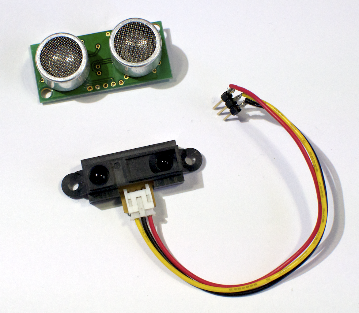
Light is used in many sensors in a variety of ways. Light-emitting diodes, light-dependent resistors, and phototransistors can be combined to sense dust, measure distance, or determine reflected color. Light is also used in some ranging sensors to determine distance from a sensor to a target.
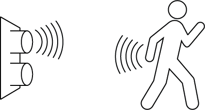
Many sensors measure movement or distance indirectly, by sending out a pulse of light or sound and reading the reflected signal when it bounces off a target as illustrated in Figure 5. These are called ranging sensors (Figure 4) because they read a range of distance.
Figure 5. Ranging sensors work by bouncing energy off the target and reading the reflection.
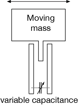
Still other sensors work by converting the energy they read into a change in capacitance. For example, accelerometers and other miniaturized electromechanical (MEMS) sensors typically have a tiny moving conductive mass at their core, suspended on tiny springs and surrounded on both sides by electrical contacts. Because the conductive mass is parallel to the outer contacts, a capacitance builds up between the contact. When the mass is moved, the capacitance changes between the two sides, effectively creating two variable capacitors as illustrated in Figure 6. That variable capacitor is then placed in a resistor-capacitor circuit to convert the change in capacitance into a changing voltage.
Figure 6. MEMS sensors often form a variable capacitor by moving a capacitive plate in between two other capacitive surfaces.
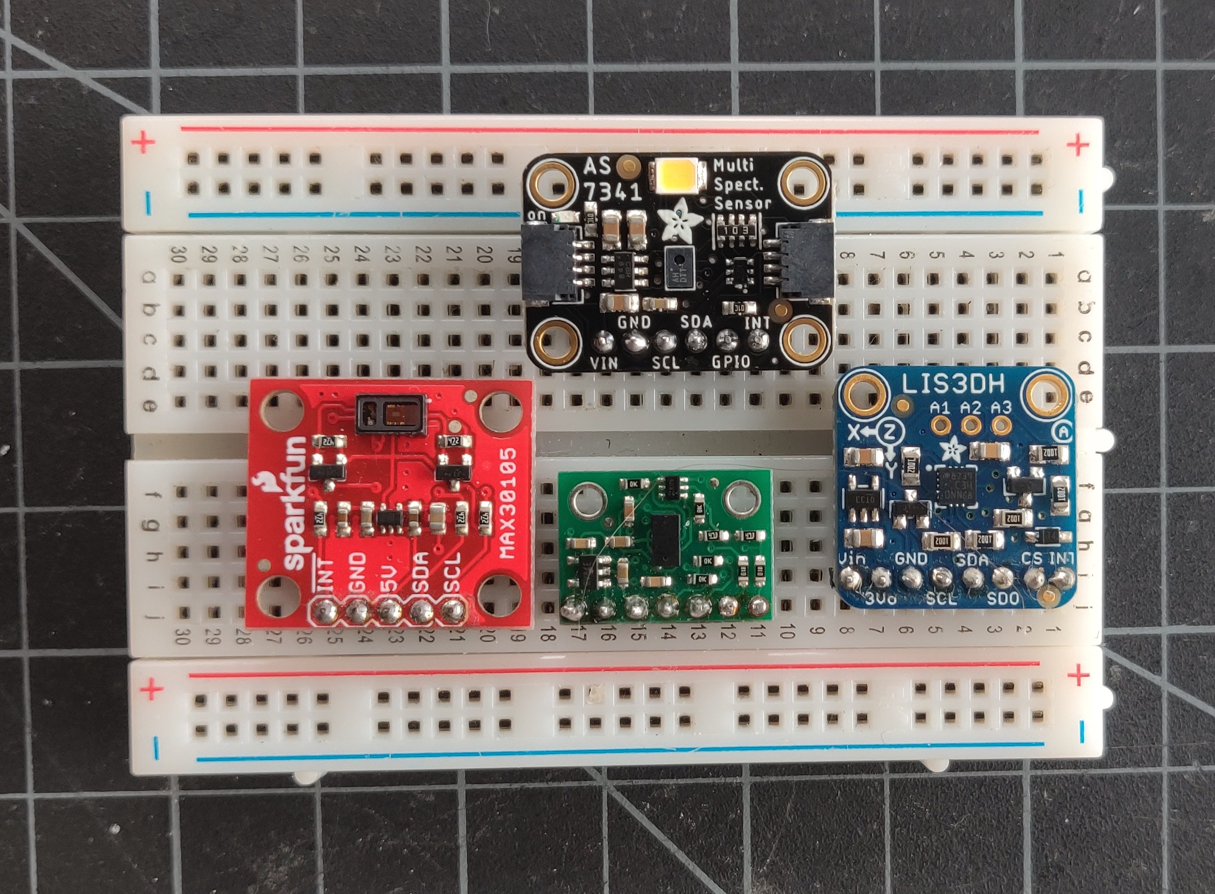
Other than switches and variable resistors, most sensors you buy are integrated circuits that include the resistance-to-voltage or capacitance-to-voltage circuit and provide you with an analog voltage output. Some will even include an analog-to-digital converter and provide you with a serial data interface, either I2C, SPI, or asynchronous serial, so that you can connect the sensor to the serial ports of your microcontroller. Still others will provide a changing pulse output, or pulse width modulation (PWM) output, where the width of the pulse represents the sensor value.
Figure 7. A collection of sensors with digital interfaces. Clockwise, from top: AS7341 spectrometer; LIS3DH accelerometer; VL53L0X Time-of-flight distance sensor; Max3010x particle detector. These sensors are on small breakout boards which can connect to a solderless breadboard. They all connect to a microcontroller using SPI or I2C.
When you shop for sensors, you need to look at the data sheet to learn how they operate. The data sheet will usually include the following essential facts:
a text description of the sensor and its operation;
a pin diagram to tell you what pins perform what functions;
a table of electrical characteristics that tells you what the supply voltage is, what the operating current is, and what the output is, along with other electrical and physical properties;
a graph or conversion formula that relates the input energy to the output energy;
a mechanical description of the sensor itself.
Some datasheets will include other information as well, such as application circuits, reliability data, and so forth.
You should follow the datasheet’s guideline for sensor operation. Don’t exceed the maximum or minimum operating voltage, and make sure to supply adequate current to operate the sensor. Avoid supplying too much current, because the excess current will get turned into heat, which often changes the sensor’s operating characteristics. Make sure you understand the sensor’s interface. Be clear on whether it’s an analog electrical property like resistance, capacitance or voltage, or a digital serial data interface. Look for typical application circuits and microcontroller code samples online if you can find them.
Once you understand how a sensor works and what its output will be, you should connect it to your microcontroller and write a simple program to read the output. Don’t jump right into writing a complex program. Write the smallest program necessary to read the sensor’s changing values and output them for debugging purposes. Then put the sensor in the physical context in which you plan to use it and read the output values in action. The range that a sensor can read will change depending on the specific conditions or actions that you plan to read. So make sure the physical setting of the sensor is as close to reality as possible in order to test it. Once you know the range of values that it’s going to output in those conditions, then you can write a function to convert the sensor’s raw output range into a range you can use. Depending on the context, you probably won’t get the full output range that the sensor is capable of delivering. So your conversion function should be based on the range you’re actually seeing, not the total range.
You probably don’t need to convert the sensor’s readings into its output voltage or its physical property. For example, if you’re using a force sensing resistor, you probably don’t need to know how many Newtons of force are being exerted on the sensor, or what the output voltage is. Instead, you probably just need to know whether someone is pressing gently, firmly, or really firmly against the sensor. Perhaps you just need a range from 0 to 10. When you write your conversion function, consider what the relevant result is for you, and write a function that delivers that result.
In this lab, you’ll connect a digital input circuit and a digital output circuit to a microcontroller. Though this is written for the Arduino microcontroller module, the principles apply to any microcontroller.
Introduction
In this lab, you’ll connect a digital input circuit and a digital output circuit to a microcontroller. Though this is written for the Arduino microcontroller module, the principles apply to any microcontroller.
Digital input and output are the most fundamental physical connections for any microcontroller. The pins to which you connect the circuits shown here are called General Purpose Input-Output, or GPIO, pins. Even if a given project doesn’t use digital in and out, you’ll often use LEDs and pushbuttons or switches during the development for testing whether everything’s working.
What You’ll Need to Know
To get the most out of this lab, you should be familiar with the following concepts and you should install the Arduino IDE on your computer. You can check how to do so in the links below:
Figures 1-8 show the parts you’ll need for this exercise. Click on any image for a larger view.
Figure 1. Arduino Nano 33 IoT
Figure 2. Jumper wires. You can also use pre-cut solid-core jumper wires.
Figure 3. A solderless breadboard
Figure 4. An 8 ohm speaker (optional).This is a good alternate to the LED if you prefer audible output.
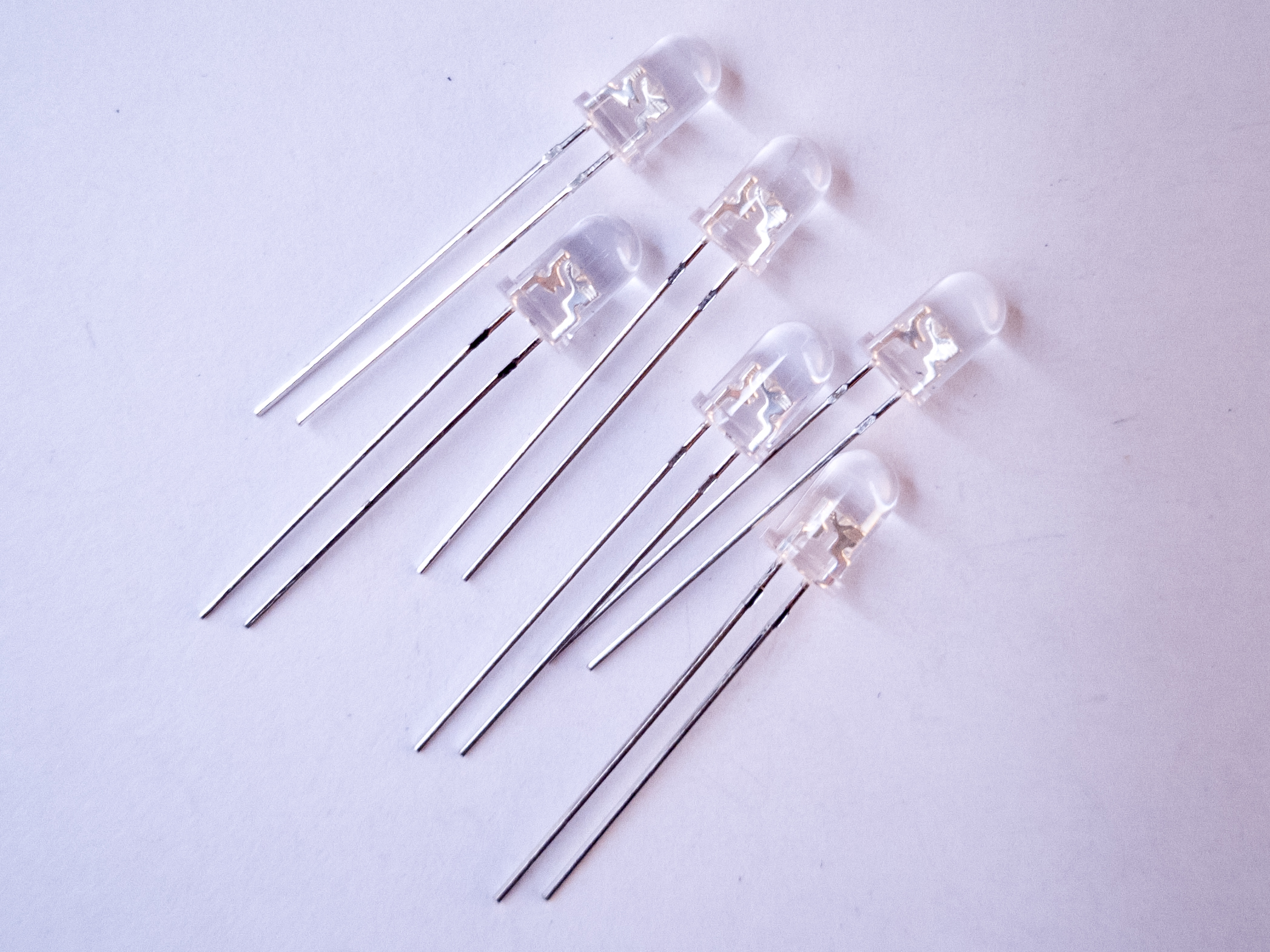
Figure 5. LEDs. The long leg goes to voltage and the short leg goes to ground
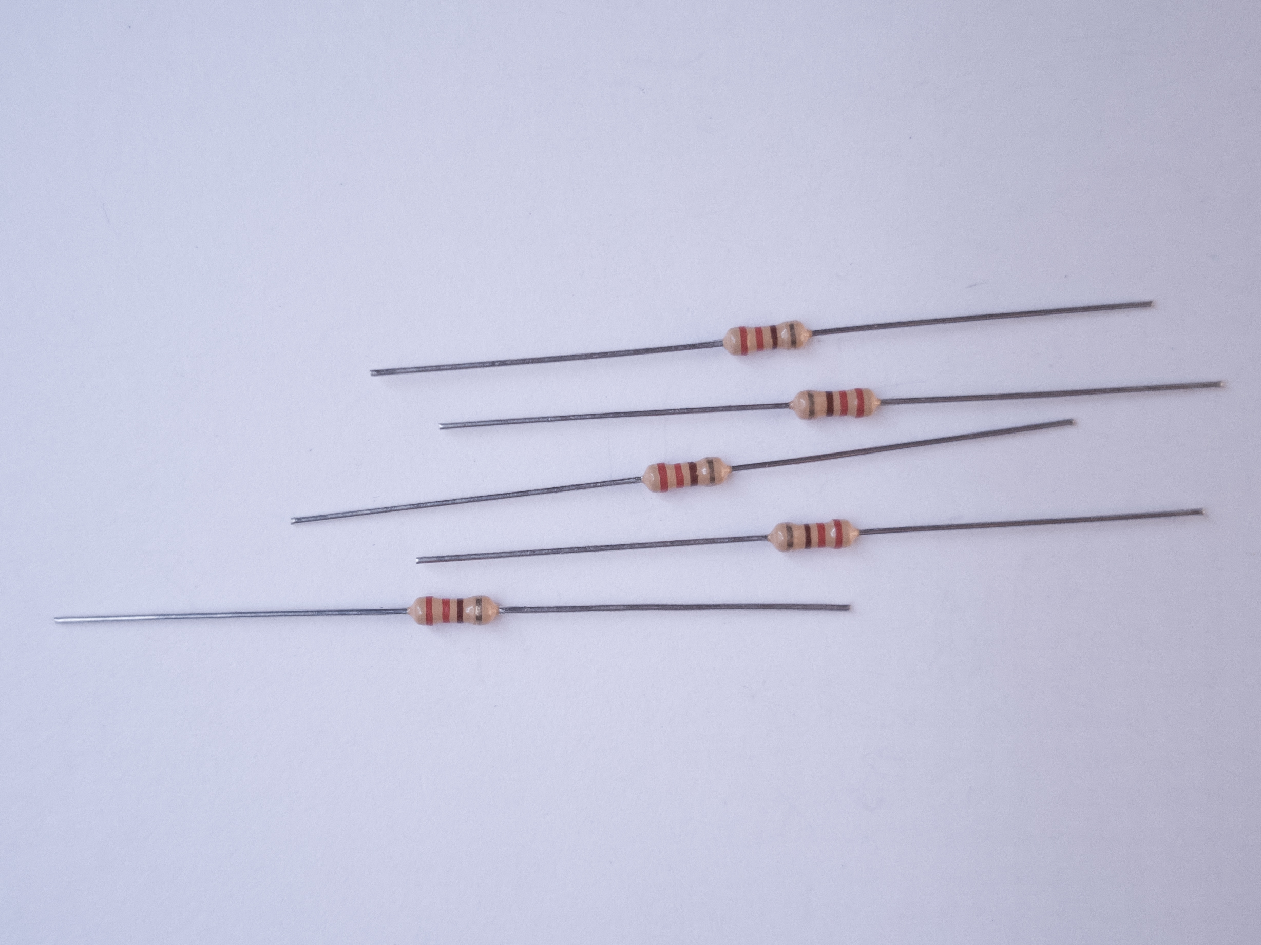
Figure 6. 220-ohm resistors. These ones are 4-band resistors. They are colored red, red, brown and gold, which signifies 2, 2 (red, red), times 10 (brown), with a 5% tolerance (gold).
Figure 7. 10-kilohm resistors. These ones are 5-band resistors. They are colored brown, black, black, red, brown, which signifies 1 (brown), 0, 0 (black, black), times 100 (red), with a 1% tolerance (brown). Four-band 10-kilohm resistors are colored brown, black, orange (1, 0, times 1000), gold (5% tolerance).
Figure 8. A pushbutton. Any switch will do the job as well.
If you’re using a brand new breadboard, you might want to check out these videos before you get started, to prep your board and care for your microcontroller.
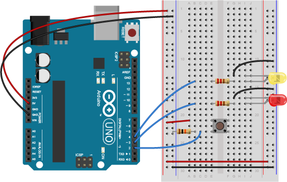
Connect power and ground on the breadboard to power and ground from the microcontroller. On the Arduino Uno, use the 5V or 3.3V (depending on your model) and any of the ground connections. Figures 9 and 10 show how to do this for an Arduino Uno and for an Arduino Nano 33 IoT.
Figure 9. Breadboard view of an Arduino Uno on the left connected to a solderless breadboard, right.
As shown in Figure 9, the Uno’s 5V output hole is connected to the red column of holes on the far left side of the breadboard. The Uno’s ground hole is connected to the blue column on the left of the board. The red and blue columns on the left of the breadboard are connected to the red and blue columns on the right side of the breadboard with red and black wires, respectively. These columns on the side of a breadboard are commonly called the buses. The red line is the voltage bus, and the black or blue line is the ground bus.
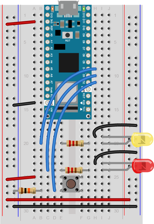
Figure 10 Breadboard view of an Arduino Nano mounted on a solderless breadboard.
As shown in Figure 10, the Nano is mounted at the top of the breadboard, straddling the center divide, with its USB connector facing up. The top pins of the Nano are in row 1 of the breadboard.
The Nano, like all Dual-Inline Package (DIP) modules, has its physical pins numbered in a U shape, from top left to bottom left, to bottom right to top right. The Nano’s 3.3V pin (physical pin 2) is connected to the left side red column of the breadboard. The Nano’s GND pin (physical pin 14) is connected to the left side black column. These columns on the side of a breadboard are commonly called the buses. The red line is the voltage bus, and the black or blue line is the ground bus. The blue columns (ground buses) are connected together at the bottom of the breadboard with a black wire. The red columns (voltage buses) are connected together at the bottom of the breadboard with a red wire.
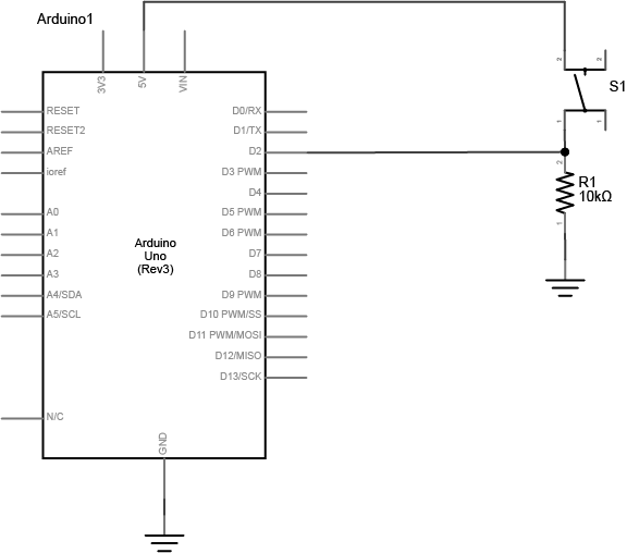
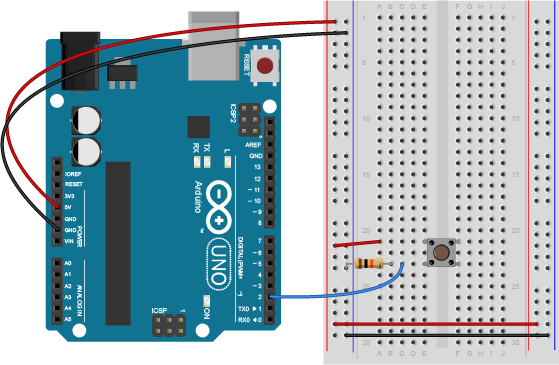
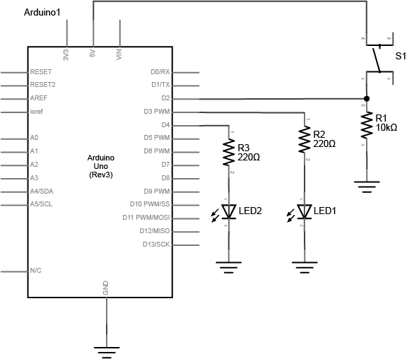
Connect a pushbutton to digital input 2 on the Arduino. Figures 11 and 12 show the schematic and breadboard views of this for an Arduino Uno, and Figure 13 shows the breadboard view for an Arduino 33 IoT. The pushbutton shown below is a store-bought momentary pushbutton, but you can use any pushbutton. Try making your own with a couple of pieces of metal as shown in the Switches lab.
If you’re not sure what pins are the inputs and outputs of your board, check the Microcontroller Pin Functions page for more information. The reference page on the standard breadboard layouts for the Uno, Nano series, and MKR series might be useful as well.
Figure 11. Schematic view of an Arduino connected to a pushbutton.
Figure 12. Breadboard view of an Arduino connected to a pushbutton.
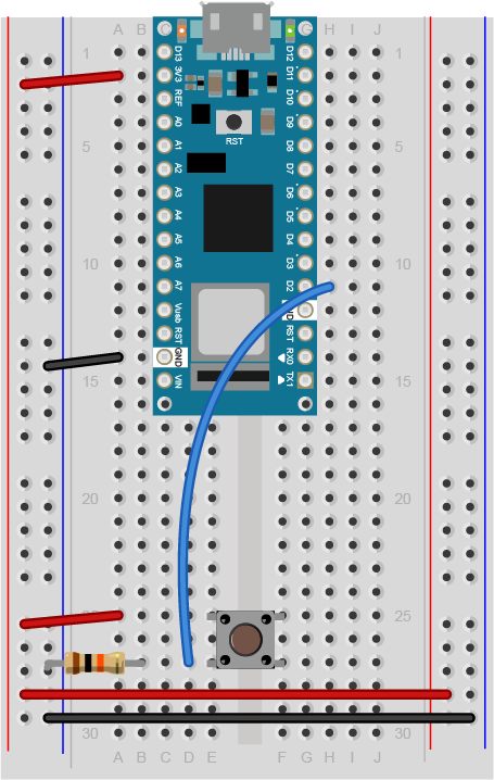
Figure 13. Breadboard view of an Arduino Nano connected to a pushbutton.
Figure 13 shows the breadboard view of an Arduino Nano connected to a pushbutton. The +3.3 volts and ground pins of the Arduino are connected by red and black wires, respectively, to the left side rows of the breadboard. +3.3 volts is connected to the left outer side row (the voltage bus) and ground is connected to the left inner side row (the ground bus). The side rows on the left are connected to the side rows on the right using red and black wires, respectively, creating a voltage bus and a ground bus on both sides of the board. The pushbutton is mounted across the middle divide of the solderless breadboard. A 10-kilohm resistor connects from the same row as pushbutton’s bottom left pin to the ground bus on the breadboard. There is a wire connecting to digital pin 2 from the same row that connects the resistor and the pushbutton. The top left pin of the pushbutton is connected to +3.3V.
Note on The Pulldown Resistor
What happens if you don’t include the resistor connecting the pushbutton to ground? The resistor connecting the pushbutton is a pulldown resistor. It provides the digital input pin with a connection to ground. Without it, the input will behave unreliably.
If you don’t have a 10-kilohm resistor for the pushbutton, you can use any reasonably high value. 4.7K, 22K, and even 1 Megohm resistors have all been tested with this circuit and they work fine. See the digital input and output notes for more about the digital input circuit.
If you’re not sure about the resistor color codes, use a multimeter to measure the resistance of your resistors in ohms, and check this resistor color code calculator.
Add Digital Outputs (LEDs)
Connect a 220-ohm resistor and an LED in series to digital pin 3 and another to digital pin 4 of the Arduino. Figures 14, 15, and 16 below show the schematic view as well as the breadboard view for both the Uno and the Nano. If you prefer an audible tone over a blinking LED, you can replace the LEDs with speakers or buzzers. The 220-ohm resistor will work with LED, speaker, or buzzer.
Figure 14. Arduino connected to pushbutton and two LEDs, Schematic view.
Figure 15. Arduino Uno connected to pushbutton and two LEDs, Breadboard view.
Figure 16. Arduino Nano connected to pushbutton and two LEDs, Breadboard view.
Note on LED Resistor Values
For the resistor on the LED, the higher the resistor value, the dimmer your LED will be. So 220-ohm resistors give you a nice bright LED, 1-kilohm will make it dimmer, and 10K or higher will likely make it too dim to see. Similarly, higher resistor values attenuate the sound on a speaker, so a resistor value above 220-ohm will make the sound from your speaker or buzzer quieter.
Make sure you’re using the Arduino IDE version 1.8.19 or later. If you’ve never used the type of Arduino module that you’re using here (for example, a Nano 33 IoT), you may need to install the board definitions. Go to the Tools Menu –> Board submenu –> Board Manager. A new window will pop up. Search for your board’s name (for example, Nano 33 IoT), and the Boards manager will filter for the correct board. Click install and it will install the board definition.
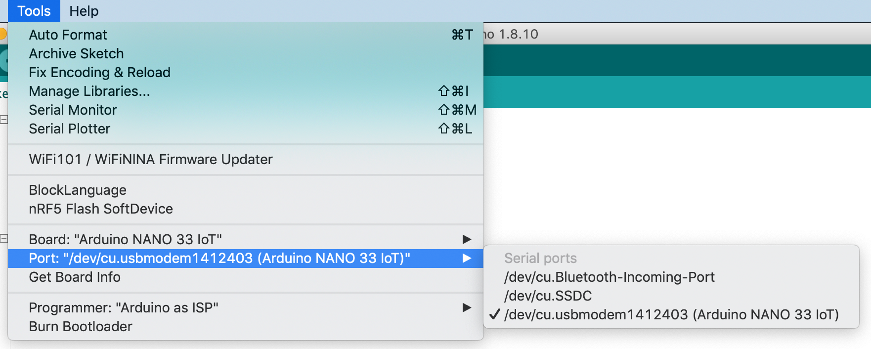
Connect the microcontroller to your computer via USB. When you plug the Arduino into your computer, you’ll find a new serial port in the Tools–>Port menu (for details on installing the software, and USB-to-serial drivers for older Arduino models on Windows, see the Arduino Getting Started Guide). In the MacOS, the name look like this: /dev/tty.usbmodem-XXXX (Board Type) where XXXX are part of the board’s unique serial number and Board Type is the board type (for example, Arduino Uno, Nano 33 IoT, MKRZero, etc.) In Windows it will be called COM and a number. Figure 17 shows the tools men and its Port submenu.
Figure 17. The Arduino Tools menu showing the Ports submenu
Now it’s time to write a program that reads the digital input on pin 2. When the pushbutton is pressed, turn the yellow LED on and the red one off. When the pushbutton is released, turn the red LED on and the yellow LED off.
In your setup() method, you need to set the three pins you’re using as inputs or outputs, appropriately.
 void setup() {
   pinMode(2, INPUT);    // set the pushbutton pin to be an input
   pinMode(3, OUTPUT);   // set the yellow LED pin to be an output
   pinMode(4, OUTPUT);   // set the red LED pin to be an output
 }
In the main loop, first you need an if-then-else statement to read the pushbutton. If you’re replacing the LED with a buzzer, the code below will work as is. If you’re using a speaker, there’s an alternative main loop just below the first one:
void loop() {
   // read the pushbutton input:
   if (digitalRead(2) == HIGH) {
     // if the pushbutton is closed:
     digitalWrite(3, HIGH);    // turn on the yellow LED
     digitalWrite(4, LOW);     // turn off the red LED
   }
   else {
     // if the switch is open:
     digitalWrite(3, LOW);     // turn off the yellow LED
     digitalWrite(4, HIGH);    // turn on the red LED
   }
 }
Here’s an alternate loop function for an audible output on two speakers. If you want to use only one speaker, try alternating the tone frequency from 440Hz (middle A) to 392Hz (middle G):
void loop() {
   // read the pushbutton input:
   if (digitalRead(2) == HIGH) {
     // if the pushbutton is closed:
     tone(3, 440);    // turn on the first speaker to 440 Hz
     noTone(4);     // turn off the second speaker
   }
   else {
     // if the switch is open:
     noTone(3);     // turn off the first speaker
     tone(4, 440);    // turn on the second speaker to 440 Hz
   }
 }
Once you’re done with that, you’re ready to compile your sketch and upload it. Click the Verify button to compile your code. Then click the Upload button to upload the program to the module. After a few seconds, the following message will appear in the message pane to tell you the program was uploaded successfully. Related video: Upload the code to the Arduino
Binary sketch size: 5522 bytes (of a 7168 byte maximum)
Press the pushbutton and watch the LEDs change until you get bored. That’s all there is to basic digital input and output!
The Uno vs Newer Boards
If you’ve used an Uno r3 board before (the “classic Uno”), and are migrating to the Nano or a newer board, you may notice that the serial connection behaves differently. When you reset the MKR, Nano, Uno R4, or Leonardo boards, or upload code to them, the serial port seems to disappear and re-appear. Here’s why:
There is a difference between the Uno R3 and most of the newer boards like the MKR boards, the Nano 33 IoT and BLE, the Leonardo and the Uno R4: the Uno R3 has a USB-to-serial chip on the board which is separate from the microcontroller that you’re programming. The Uno R3’s processor, an ATMega328, cannot communicate natively via USB, so it needs the separate processor. That USB-to-serial chip is not reset when you upload a new sketch, so the port appears to be there all the time, even when your Uno R3 is being reset.
The newer boards can communicate natively using USB. They don’t need a separate USB-to-serial chip. Because of this, they can be programmed to operate as a mouse, as a keyboard, or as a USB MIDI device. Since they are USB-native, their USB connection gets reset when you upload new code or reset the processor. That’s normal behavior for them; it’s as if you turned off the device, then turned it back on. Once it’s reset, it will let your computer’s operating system know that it’s ready for action, and your serial port will reappear. This takes a few seconds. It means you can’t reset the board, and then open the serial port in the next second. You have to wait those few seconds until the Arduino board has made itself visible to the computer’s operating system again.
If you have problems with the UBS-native boards’ serial connection, tap the reset button once, then wait a few seconds, then see if the port shows up again once the board has reset itself. You can also double-tap the reset on the MKR and Nano boards to cause the processor to reset and go into a sleep mode. In this mode, the USB connection will reset itself, but your sketch won’t start running. The built-in LED will glow softly. Then upload a blank sketch. From there, you can start as if your board was brand new.
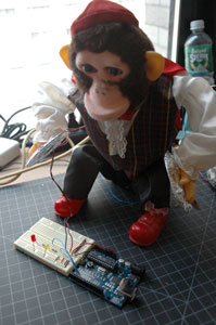
Many projects can be made with just digital input and output. For example, a combination lock is just a series of pushbuttons that have been pushed in a particular sequence. Consider the cymbal-playing monkey in Figures 18-20:
Figure 18. A mechanical toy monkey that plays cymbals. The cymbals are covered with aluminum foil. The foil is connected to wires, and the wires are connected to an Arduino and breadboard. The two wires from the cymbals act as a switch when they are hit together.
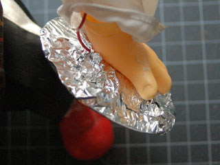
The monkey’s cymbals can be turned into a switch by lining them with tin foil and screwing wires to them:
Figure 19. Detail of the cymbal monkey’s cymbal. It is covered with aluminum foil, as described above.
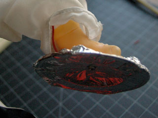
Figure 20. Detail of the other cymbal. This one is also covered with aluminum foil.
Those wires can be run to a breadboard and used as a switch. Then the microcontroller could be programmed to listen for pattern of cymbal crashes, and if it sees that pattern, to open a lock by turning on a digital output.
Consider the project ideas from Project 1 for more applications you can do with simple input and output.
Different kinds of computers are designed for different purposes. The computer at the heart of your laptop is optimized for different purposes than the one in your phone or the one in your mouse. The simplest computers are those that are designed to take inout from the physical world and control output devices in the physical world. These are called microcontrollers.
Most electronic devices you use today have a microcontroller at their core. Microcontrollers are optimized for control of physical input and output. They’re generally less computationally capable than the processors used in multimedia computers or servers, for example. They require less power than a those other processors, and they’re easier to interface with the physical world through input circuits called sensors and output circuits called actuators. They can communicate with other processors through various communication interfaces.
Computer, microcontroller, processor? Which is which?
You’ll hear these terms thrown around interchangeably here and in other writing about computers. Computer and processor are generic terms for the anything that can run a program, basically. Controller or microcontroller is usually reserved for a simple processor that does only one task, like listening to sensors. In explaining microcontrollers, we’ll distinguish them from personal computers or servers, which contain more powerful processors that can run an operating system.
Microcontrollers: Computers for the Physical World
When you’re building something that controls digital media from the physical world, it’s common to use microcontrollers to sense the user’s actions, then pass information about those actions to a multimedia processor like the one in your laptop. Keyboards and computer mice have microcontrollers inside that communicate with personal computers using the USB communications protocol.
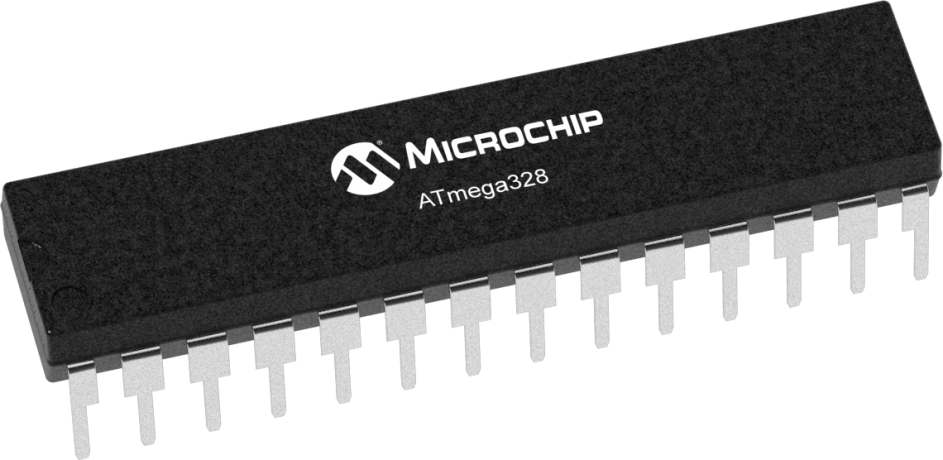
Figure 1. Atmel Atmega328P chipFigure 2. Atmel Atmega328P chipFigure 3. SMD package of a microcontroller
Microcontrollers come in many different size packages as shown in Figure 1, Figure 2 and Figure 3.
Like any other computer, a microcontroller has to have input ports to detect action by a user, and output ports through which it expresses the results of its programs. The metal pins or contact points on a microcontroller are the inputs and outputs. Other devices, like light, heat, or motion sensors, motors, lights, our sound devices, are attached to these pins to allow the microcontroller to be sensitive to the world and to express itself. A microcontroller also requires power connections and communications connections, just like any other computer.
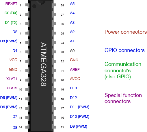
Figure 4 shows an Atmel (now owned by Microchip) microcontroller with its pins labelled. You can see which ones are general purpose input and output (GPIO), which ones are for power and communications, and which ones have specialty functions as well, the most common of which is analog input. For more on the typical functions of a microcontroller, see the Microcontroller Pin Functions page.
Figure 4. ATMEGA328 pin diagram
There are several different types of microcontrollers. The simplest have very little program memory, only one or two GPIO pins and no specialty functions. These might only cost a fraction of a dollar apiece in large quantities. Slightly more capable ones will have more memory, more GPIO pins and will include specialty functions as well, such as dedicated pins for particular communications protocols. The Atmega328 processor that’s at the heart of the Arduino Uno is one of these processors. The SAMD21 at the heart of the Nano 33 IoT is its more modern cousin. You can buy these processors for a few dollars apiece in quantity. More powerful than those are the controllers that have connections to interface to a display screen, like those in your mobile phone. These might cost several dollars, or tens of dollars. The more memory, processing power and input/output ports that a microcontroller has, the more expensive it tends to be.
When your device is complex enough to need an operating system, it might contain several controllers and processors. The controls for displays, power, and physical I/O are usually farmed out to microcontrollers, while the central processor runs the operating system, communicating with each lesser processor as needed.
The line between microcontrollers and operating system processors is getting blurry these days, so it helps to understand types of programs that different devices might run in order to understand the difference.
Programs for Microcontrollers and Other Processors
Programs for any processors fall into a few different classes: firmware, bootloaders, basic input-output systems, and operating systems. When you understand how they’re all related, you gain a better picture of how different classes of processors are related as well.
Microcontrollers generally run just one program as long as they are powered. That program is programmed onto the controller from a personal computer using a dedicated hardware programming device. The hardware programmer puts the program on the controller by shifting the instructions onto it one bit at a time, through a set of connections dedicated for this purpose. If you want to change the program, you have to use the programmer again. This is true of any processor, by the way: even the most powerful server or multimedia processor has to have a piece of firmware put on it with a hardware programmer at first.
Microcontrollers generally don’t run operating systems, but they often run bootloaders. A bootloader is a firmware program that lives in a part of the controller’s memory, and can re-program the rest of that memory. If you want to program a microcontroller directly from a personal computer without a separate hardware programmer, or from the internet, then you need a bootloader. Whenever your phone is upgrading its firmware, it’s doing it through a bootloader. Bootloaders allow a processor to accept new programs through more than just the dedicated programming port.
Any processor that runs an operating system will run a Basic Input-Output System, or BIOS as well. A BIOS may be loaded onto a processor using a bootloader. A BIOS runs before, or instead of, the operating system. It can control any display device attached to the processor, and any storage attached (such as a disk drive), and any input device attached as well.
Bootloaders and BIOSes are often called firmware because they’re loaded into the flash memory of the processor itself. See Table 1 for types of firmware. Other programs live on external storage devices like disk drives, and are loaded by the BIOS. These are what we usually think of software. Table 2 shows different kinds of software. When you change a processor’s firmware, you need to stop the firmware from running, upload the new firmware, and reset the processor for the changes to take effect. Similarly, when you change a microcontroller’s program, you stop the program, upload the new one, and reset the microcontroller.
An operating system is a program that manages other programs. The operating system schedules access to the processor to do the tasks that other programs need done, manages network and other forms of communications, communicates with a display processor, and much more.
Programs are compiled into the binary instructions that a processor can read using programs called compilers. A compiler is just one of the many applications that an operating system might run, however. The applications that an operating system runs also live on external storage devices like disk drives.
Firmware
Stored On
Detail
Single Program
Processor’s program memory
Is the only program running; must be loaded by hardware programmer
Bootloader
Processor’s program memory
Must be loaded by hardware programmer; Takes small amount of program memory; can load another program into the rest of program memory
BIOS
Processor’s program memory
Usually loaded by bootloader; can load operating system into RAM memory
Table 1. Types of firmware that are stored directly on a microprocessor
Software
Stored on
Details
Operating System
External mass storage
Runs other programs; loaded into RAM by BIOS; unloaded from RAM on reset
Drivers
External mass storage
Controls access to other processors, like disk drivers, keyboards, mice, screens, speakers, printers, etc. These are usually loaded into RAM on startup of the OS, and controlled by the OS, not the user.
Applications
External mass storage
Loaded into RAM by operating system and unloaded as needed
Table 2. Types of software on an operating system processor, and where they are stored.
Generally, the term microcontroller refers to firmware-only processor, and a processor that runs an operating system from external storage is called an embedded processor, or a central processor if it’s in a device with lots of other processors. For example, the Arduino is a microcontroller. The Raspberry Pi and BeagleBone Black are embedded processors. Your laptop are multi-processor devices running a central processor, a graphics processor, sound processor, and perhaps others.
Microcontroller Development Boards and Activity Boards
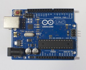
A processor, whether microcontroller or multimedia processor, can’t operate alone. It needs support components. For a microcontoller, you need at least a voltage regulator and usually an external clock called a crystal. You might also add circuitry to protect it in case it’s powered wrong, or in case the wrong voltage and current are plugged into the IO pins. You might include communications interfaces as well. This extra circuitry determines the base cost of a development board like the Arduino (Figure 5) or the Raspberry Pi (Figure 6).
Development boards usually include:
The processor itself
Power regulation circuitry
Hardware programmer connector
Communications interface circuitry
Basic indicator LEDs
Figure 5. An Arduino Uno.Figure 6. A Raspberry Pi
More advanced development boards might also include multiple communications interface circuits, including wireless interfaces; sensors already attached to some of the GPIO pins; a mass storage connector like an SD card; and video or audio circuitry, if the processor supports that. The more features a board offers, the more it costs.
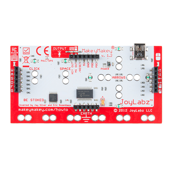
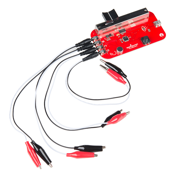
A development board allows you to program the controller’s firmware and software, but an activity board may not. Activity boards contain a pre-programmed microcontroller and some sensors and actuators along with a communications interface and a communications protocol so that you can interface the board and its sensors and actuators with software running on your personal computer. Boards like the MaKey MaKey (Figure 7) or the PicoBoard (Figure 8, now retired) are activity boards. Activity boards generally can’t operate on their own without being connected to a personal computer, while development boards can.
Figure 7. A Makey Makey BoardFigure 8. A Sparkfun Picoboard
Do I Really Need A Development Board?
You can buy and program microcontrollers without a development board or activity board, but you’ll need some extras to do so. First, you’ll need to design your own support circuitry, at least a programmer interface and a power supply. You’ll need a hardware programmer as well, in most cases. And you’ll need to buy breakout boards or learn to make very small surface-mount circuits, since fewer and fewer microcontrollers come in the large dual inline package (DIP) that can plug into a solderless breadboard anymore. Generally, until you are very comfortable with electronics and circuit fabrication, it’s best to start with an activity board or a development board.
Toolchains and Development Environments
The two most common languages for microcontrollers are the assembly language of each particular processor, or the C programming language. More modern processors are starting to be developed in Python as well. A toolchain is the combination of compilers and linkers needed to convert the instructions you write into a binary file that the microcontroller can interpret as its instructions and the programmer software needed to upload that into the processor. Every manufacturer and processor family has its own assembly language (the beginning of the toolchain), but there’s a C compiler for almost every microcontroller on the market. Beyond that, a toolchain might include a compiler or firmware to convert a higher level language into the controller’s assembly language. If it’s a scripted language like Python, then the microcontroller’s firmware might include a Python interpreter that remains on the controller as your various scripts are swapped for one another in development.
A toolchain does the work of converting your code, but an integrated development environment (IDE) is needed to connect you, the programmer, to the toolchain. An IDE usually contains a text editor with user interface elements to send your text to the toolchain and upload the result to the processor. IDEs will also include a display to give you error messages about your code, and a monitor of some sort so that you can see what your code does when it’s running on the processor.
Things to consider when picking a microcontroller:
Here’s a guide to picking a microcontroller for this class. What follows are the economic considerations for picking a microcontroller more generally.
Costs
How much do I want to spend? The more features and flexibility, the higher the cost. But if it reduces the time taken between setting up and expressing yourself, it may be worth spending the extra money.
Time
How much work do I want to do?
An activity board or higher level development board will generally minimize the amount of work you do to build your interface to the world. Lower level dev boards or building your own boards will take more work before you have things working. Don’t go build your own boards unless you have to. Many good projects never get completed on time because the maker wanted to use their project as a way to learn how to make a circuit.
What programming languages/communications protocols/electronics do I already know?
All other things being equal, pick a system whose components you know something about.
What’s the knowledge base like?
Most microcontrollers have several websites and listserves dedicated to their use and programming. Quite often, the best ones are linked right off the manufacturer’s or distributor’s website. Check them out, look at the code samples and application notes. Read a few of the discussion threads. Do a few web searches for the microcontroller environment you’re considering. Is there a lot of collected knowledge available in a form you understand? This is a big factor to consider. Sometimes a particular processor may seem like the greatest thing in the world, but if nobody besides you is using it, you’ll find it much harder to learn.
Expandability/Compatibility
What other components is the microcontroller compatible with?
Can you add on modules to your microcontroller? For example, are their motor controllers compatible with it? Display controllers? Sensors or sensor modules? Often these modules are expensive but they just snap into place without you making any special circuitry. If your time is worth a great deal, then these modules are a good buy. Sometimes even if you know how to build it with a lower level controller, a higher level system is worth the cost because it saves building and maintenance time.
What do I have to connect to?
Are you connecting to a MIDI synthesizer? A DMX-512 lighting board? A desktop computer? The phone system? The Internet? Different microcontrollers will have different interface capabilities. Make sure you can connect everything together. Sometimes this requires some creative combinations of controllers if no one controller can speak to all the devices you want it to speak to.
Physical and Electrical Characteristics
How many inputs/outputs do I need? Every system has a certain number of ins and outs. If you can, decide how many things you want to sense or control before you pick your controller.
What kinds of inputs and outputs do I need? Do you need analog inputs and outputs, for sensing changing values, or do you only need digital ins and outs, for sensing whether something is on or off? Most of the embedded Linux boards (for example, the Raspberry Pi) do not have analog inputs, so be careful of that.
What kind of power is available to me? Does it need to be battery powered? Does it need to match the voltage of another device? Does it need to draw very little amperage?
How fast do I need to process data? Lower level processors will generally give you more speed.
How much memory do I need? If you’re planning some complex data processing or logging, you may need a microprocessor with lots memory, or the ability to interface with external memory.
How small does it need to be? A lower level controller generally lets you build your own circuitry, allowing you to reduce the size of the hardware you need.
The Economics of Microcontroller Development
So where does this leave you, the hobbyist or beginner with microcontrollers? What should you choose?
Using mid-level microcontrollers will cost you relatively little up front, in terms of peripherals. The various components you’ll need to make a typical project will run you about $75 – $100, including the controller. Starter kits are a good investment if you’ve never done it before, as they get you familiar with the basics. If you know your way around a circuit, you can start with just a development board. You can always keep the project intact and re-use the microcontroller for other projects. You’ll save yourself time not having to learn how a hardware programmer works, or which compiler to choose, or how to configure it. For the beginner seeking immediate gratification, mid-level is the way to go. The only downside is that if you want to build many more projects, you’ve got to buy another development board.
Using the controllers by themselves, on the other hand, is more of a hassle up front. You’ve got to know how to build the basic support and communications circuits, how to use a hardware programmer, and how to set up a toolchain. You’ll spend a lot of time early on cursing and wishing you’d bought a development board. The advantage comes a bit later on, once everything’s set up. You’ll eventually save money on development boards, and can make them in any shape you want. It gets better the longer you continue making microcontroller projects. So start with development or activity boards, and move up as your needs demand and knowledge can accommodate.
This is an introduction to basic digital input and output on a microcontroller. In order to get the most out of it, you should know something about the following concepts. You can check how to do so in the links below:
When you’re trying to sense activity in the physical world using a microcontroller, the simplest activities you can sense are those in which you only need to know one thing about the physical world: Whether something is true or false. Is the viewer in the room or out? Are they touching the table or not? Is the door open or closed? In these cases, you can determine what you need to know using a digital input, or switch.
Digital or binary inputs to microcontrollers have two states: off and on. If voltage is flowing, the circuit is on. If it’s not flowing, the circuit is off. To make a digital circuit, you need a circuit, and a movable conductor which can either complete the circuit, or not.
Figure 1. Schematic of a Digital Input to a microcontroller
Figure 1 shows the electrical schematic for a digital input to a microcontroller. The current has two directions it can go to ground: through the resistor or through the microcontroller. When the switch is closed, the current will follow the path of least resistance, to the microcontroller pin, and the microcontroller can then read the voltage. The microcontroller pin will then read as high voltage or HIGH. When the switch is open, the resistor connects the digital input to ground, so that it reads as zero voltage, or LOW.
On an Arduino module, you declare the pin to be an input at the top of your program. Then you read it for the values 1 (HIGH) or 0 (LOW), like so:
void setup() {
 // declare pin 2 to be an input:
 pinMode(2, INPUT);
 declare pin 3 to be an output:
 pinMode(3, OUTPUT);
}

void loop() {
 // read pin 2:
 if (digitalRead(2) == 1) {
   // if pin 2 is HIGH, set pin 3 HIGH:
   digitalWrite(3, HIGH);
 } else {
   // if pin 2 is LOW, set pin 3 LOW:
   digitalWrite(3, LOW);
}
Digital output
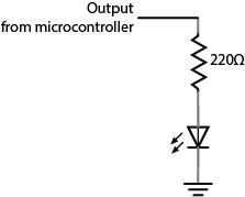
Just as digital inputs allow you to sense activities which have two states, digital or binary outputs allow you to control activities which can have two states. With a digital output you can either turn something off or on. Figure 2 is the schematic diagram for digital output controlling an LED:
Figure 2. Schematic of and led as a digital output from a microcontroller
On an Arduino module, you declare the pin an output at the top of the program just like you did with inputs. Then in the body of the program you use the digitalWrite() command with the values HIGH and LOW to set the pin high or low, as you’ve seen above. Here’s a simple blinking LED program in Arduino:
As inputs, the pins of a microcontroller can accept very little current. Likewise, as outputs, they produce very little current. The electrical signals that they read and write are mainly changes in voltage, not current. When you want to read an electrical change that’s high-current, you limit the current input using a resistor. Similarly, when you want to control a high-current circuit, you use a transistor or relay, both of which allow you to control a circuit with only small voltage changes and minimal current. Related video: Transistor