Lab: Serial Communication with Node.js

In this lab you’ll connect a microcontroller to a web browser using the node.js programming environment, HTML, and JavaScript.

Introduction

You can write programs that handle serial communication in many different languages. This page introduces how to do it using node.js. Node is a JavaScript environment that allows user to write web server programs. Below, you’ll use it to connect a microcontroller to a web browser using the node.js programming environment, HTML, and JavaScript.

To get the most out of this tutorial, you should know what a microcontroller is and how to program a microcontroller. You should also understand asynchronous serial communication between microcontrollers and personal computers. You should also understand the basics of command line interfaces.

You will struggle with this tutorial if you aren’t familiar with JavaScript.  For more on JavaScript, see Douglas Crockford’s JavaScript: The Good Parts, Manuel Kiessling’s  the Node Beginner Book, or Shelley Powers’ Learning Node.

The current version of this tutorial works with version 6.x.x of the node-serialport library.

This node.js introductory video will help in understanding this lab. The code in the video is different than this lab, but the basic concepts are similar. This lab simplifies the process a bit.

Node.js

The JavaScript programming language is mainly used to add interactivity to web pages. All modern browsers include a JavaScript interpreter, which allows the browser to run JavaScript code that’s embedded in a web page. Google’s JavaScript engine is called v8, and it’s available under an open source license. Node.js wraps the v8 engine up in an application programming interface that can run on personal computers and servers. On your personal computer, you run it through the command line interface.

Node was originally designed as a tool for writing server programs, but it can do much more. It has a library management system called node package manager or npm that allows you to extend its functionality in many directions. There is also an online registry of node libraries, npmjs.org. You can download libraries from this registry directly using npm. Below you’ll see npm used to add both serial communication functionality and a simple server programming library to node.

To get started, download the node.js installer and install it on your computer. Then open your command line terminal. On OSX, open the Terminal app, which can be found in the Applications/Utilities directory. On Windows, go to the start menu and type cmd then press enter to open a window to the command line.

If you’ve never used a command line interface, check out this tutorial on the Unix/Linux command line interface.  From here on out, you’ll see the command prompt indicated like this:

yourname@yourcomputer ~ $

Any commands you need to type will follow the $ symbol. The actual command prompt will vary depending on your operating system. On Windows, it’s typically this: >. On most Unix and Linux systems, including OSX, it’s $ or %.

When you’ve installed node.js, type this command at the command prompt to get the version of node that you’re running:

$ node -v

If you installed it correctly, you’ll get a version number like 12.18.0. The node installer should also install the node package manager (npm). You can check that in the same way:

$ npm -v

Once node and npm are in place, you’re ready to create a new project.

Related video: Install the serialport Node module

Hello from Node.js

There’s a library for node.js that allows you to communicate over your computer’s serial ports called serialport. If your computer’s connected to the internet, you can download install it automatically using npm. Create a new directory for your project:

$ mkdir nodeSerialExample

Then change directories to that directory:

$ cd nodeSerialExample


Now make a new text file in that directory with the name index.js.

This will be your main program file.  Add the following text to the file:

1
console.log("Hello, and welcome to node.");

Save the file, then run it by typing the following on the command line:

$ node index.js

Your program should print out:

Hello, and welcome to node.

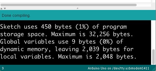
The program will finish and return to the command line when it’s done. Seeing that script running is indication that node.js is fully working on your machine.

You can also pass information into your node program using the process arguments on the command line.  Change your program like so:

1
2
var name = process.argv[2];
console.log("Hello, and welcome to node," + name);

Run this as you did before, but add your name after the name of your program when you invoke it, like so:

$ node index.js Tom

You’ll get the following:

Hello, and welcome to node, Tom

The command line arguments are passed to your program as an array. The name was the third word you typed, or array element 2 (counting “node” as element 0 and “index.js” as element 1).  This is a useful technique, and you’ll see it later to pass the program your serial port’s name.

The Node Serialport Library

You’ll also need the node serialport library, which you can install from the npm registry like so:

$ npm install serialport

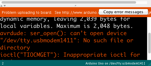
This command will make a new subdirectory called node_modules, and in that directory it will install all the necessary assets for the serialport library.  You’ll see a lot of text go by, and hopefully no errors. If you get errors, consult npmjs.org and the github wiki for serialport. Now you’re ready to use the serialport library.

The first thing you’ll want is a list of the serial ports. Replace the text of your program file with the following:

1
2
3
4
5
6
7
let serialport = require('serialport');
 
// list serial ports:
serialport.list().then (
  ports => ports.forEach(port =>console.log(port.path)),
  err => console.log(err)
)

Note: What’s With This Crazy Syntax?

If you’re new to JavaScript, this syntax may be confusing. Node.js examples tend to use anonymous functions frequently. JavaScript can pass functions as variables (and vice versa).  This is also using the JavaScript ES6 arrow function notation. That’s what’s going on here.

Stoyan Stefanov’s JavaScript Patterns is useful for understanding the various patterns of JavaScript coding.

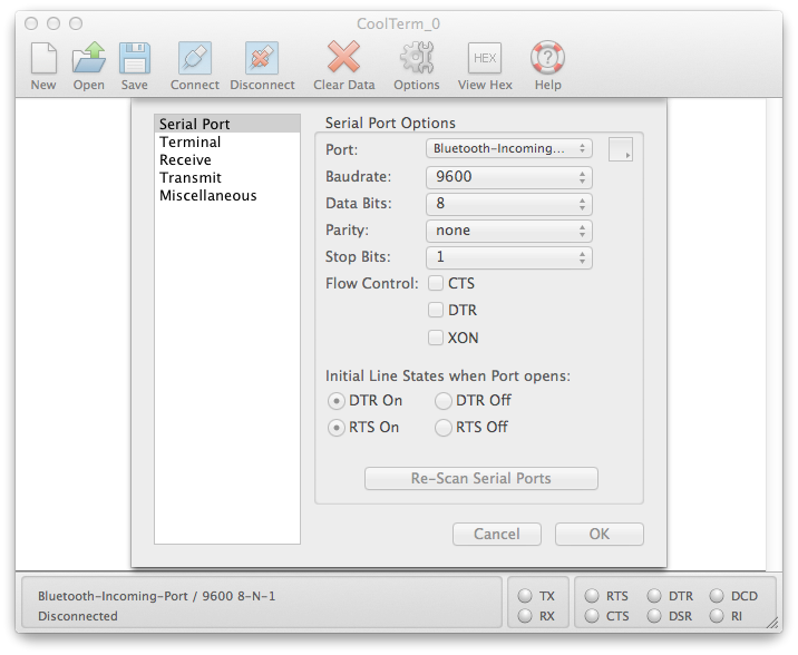
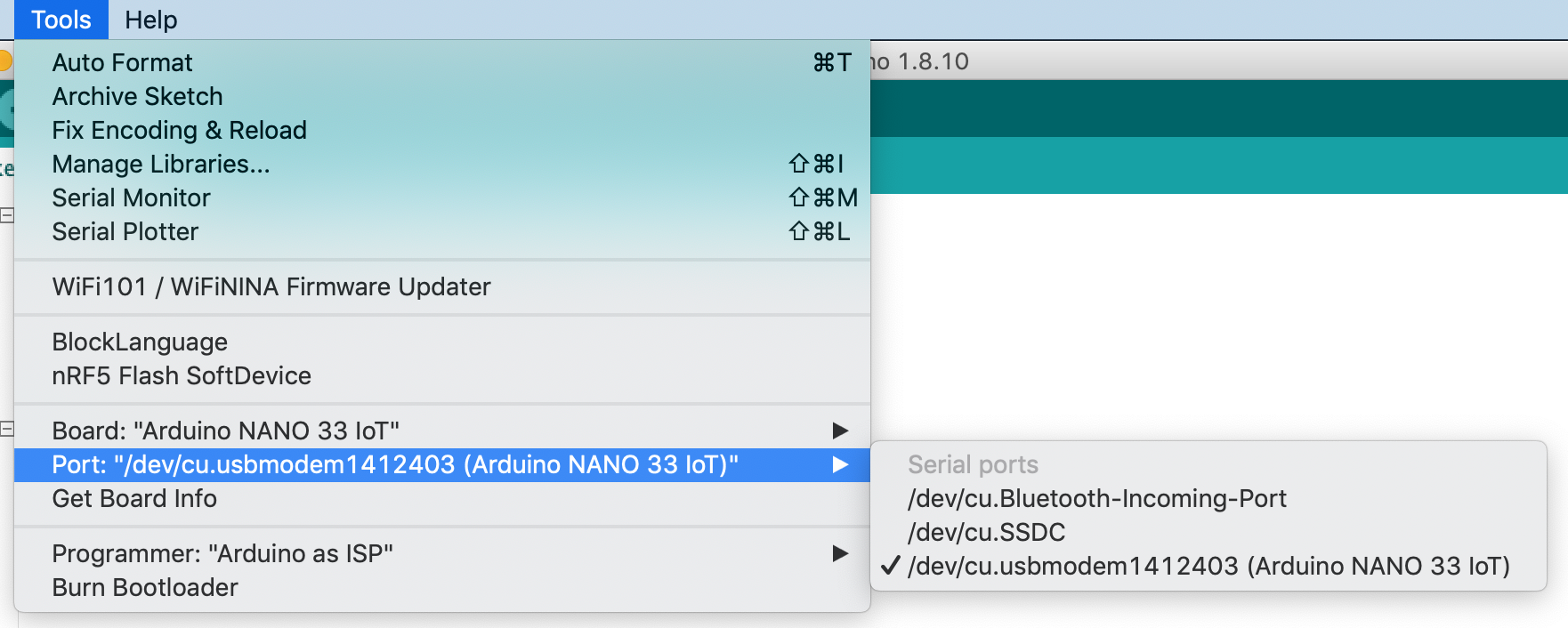
When you run this script, you’ll get a list of your serial ports like so:

$ node ListPorts.js
/dev/cu.Bluetooth-Incoming-Port
/dev/cu.Bluetooth-Modem
/dev/cu.usbmodem1411

If you’ve got an Arduino plugged in via USB, you should see the name of your board’s port there as well. In the example above, which was run on OSX, the Arduino’s port is /dev/cu.usbmodem1411.

The process of using the serialport library will be the same every time:

  • initialize the serialport library
  • open the serial port
  • set up the callback functions and let them do the rest

Which are all explained below.

Opening the Serial Port

To open a serial port in node, you include the library at the beginning of  your script, and make a local instance of the library in a variable. Make a new script or replace index.js with the following:

1
2
3
let serialport = require('serialport');// include the library
// get port name from the command line:
let portName = process.argv[2];

Then you open the port using new() like so:

1
let myPort = new SerialPort(portName, 9600);

Note the serial parameters, which are passed to the new() function after the port name, as a list. The only one used here is the baud rate, set to 9600 bits per second.

If you want to read serial data as ASCII-encoded text, line by line, you also need to create a parser to tell the serial library how to interpret data when it comes in. It should read all the incoming data as a line of text, and generate a new data event when it sees  a newline (“\n”). The parser is doing the same thing as Processing’s Serial.bufferUntil() function does. You do it like so:

1
2
3
let Readline = SerialPort.parsers.Readline; // make instance of Readline parser
let parser = new Readline(); // make a new parser to read ASCII lines
myPort.pipe(parser); // pipe the serial stream to the parser

You can find the full program so far at this link.

The Program Won’t Stop!

When you run this program now, it won’t automatically stop and return to the command line. To stop it, you’ll need to type control-C in the terminal window to stop it.   The new instance of Serialport created a software object that listens for events from the serial port. Any node.js script that creates an event listener like this will run until you explicitly stop it.  Both the serialport library and the http library, which you’ll use below, generate event listeners and will need to be explicitly stopped using control-C.

Serialport Library Events

The serialport library, like most node.js libraries, is event-based. This means that when the program is running, the operating system and the user’s actions will generate events and the program will provide functions to deal with those events called callback functions.

The main events that the serial library will deal with are when a serial port opens, when it closes, when new data arrives, and when there’s an error. The data event in particular performs the same function as Processing’s serialEvent() function.  Once you’ve made an instance of the serialport library using the new() function as shown above, you define what functions will get called when each event occurs by using serialport.on() like so:

1
2
3
4
myPort.on('open', showPortOpen);
parser.on('data', readSerialData);
myPort.on('close', showPortClose);
myPort.on('error', showError);

The functions that are called by the event are the callback functions. In the example above, when the serial port is opened, the showPortOpen function will get called. When new data arrives, the sendSerialData function will get called, and so forth. If the event generates any parameters (for example a new data event will have the data as a parameter), those parameters will get passed to the callback function.

In the example above, you’re listening for the open, close, and error events using functions from the serial port object (e.g. myPort.on('open', showPortOpen);), but you;’re listening for the data event using a function from the parser object (parser.on('data',readSerialData);). You can listen with the serial port object too (e.g.myPort.on('data',readSerialData);), but the port object listener function generates a data event once every byte, while the parser object lets you generate a data event once every newline instead.

Write the callback functions for these events like so:

1
2
3
4
5
6
7
8
9
10
11
12
13
14
15
function showPortOpen() {
  console.log('port open. Data rate: ' + myPort.baudRate);
}
 
function readSerialData(data) {
  console.log(data);
}
 
function showPortClose() {
  console.log('port closed.');
}
 
function showError(error) {
  console.log('Serial port error: ' + error);
}

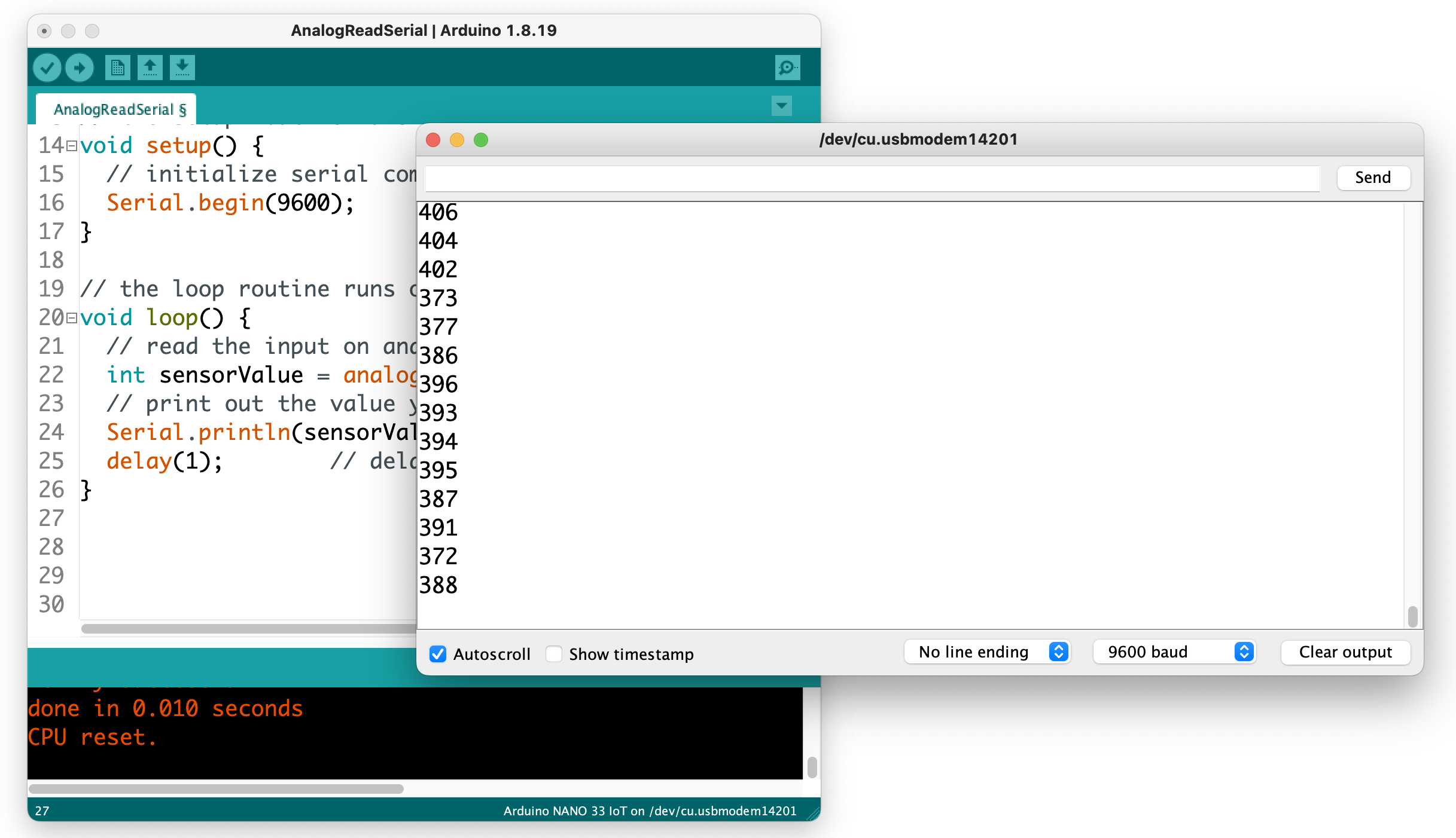
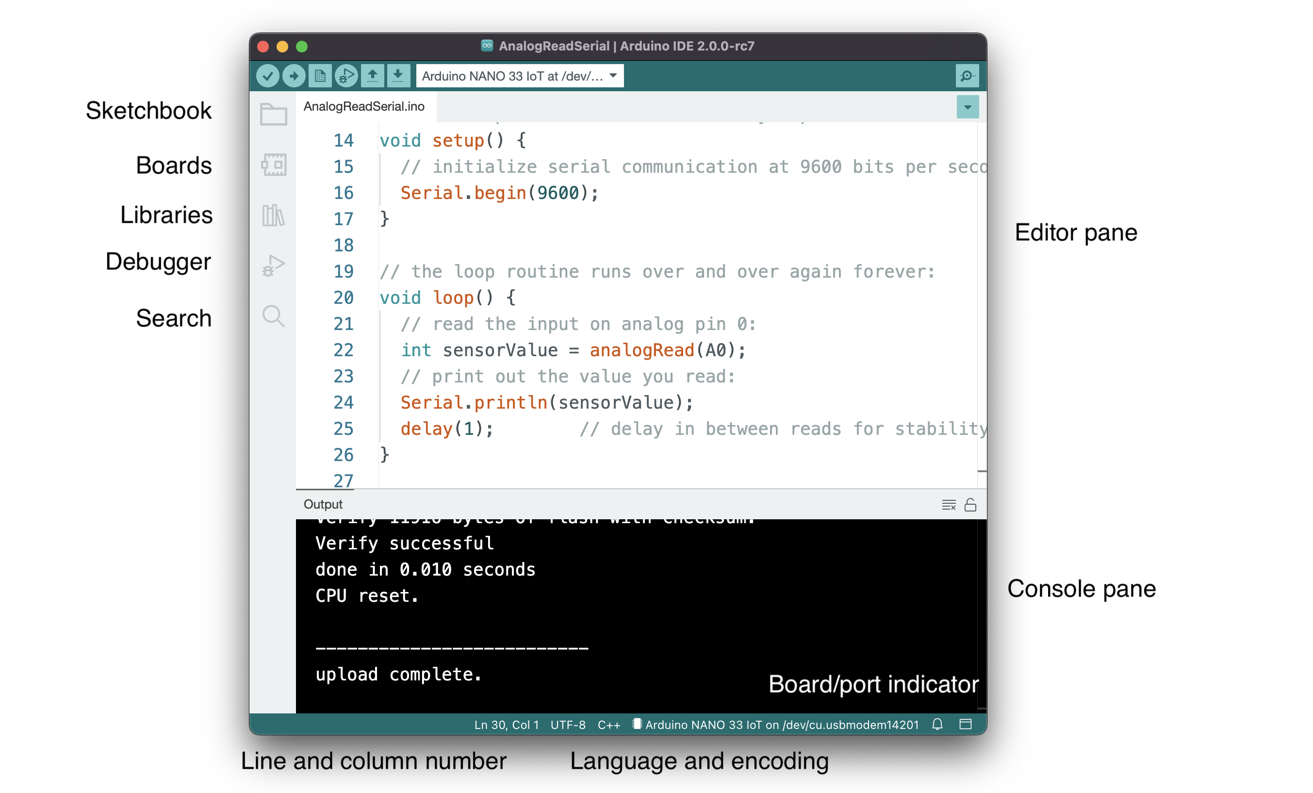
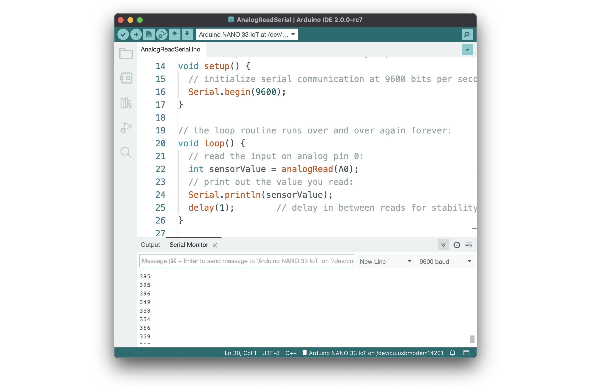
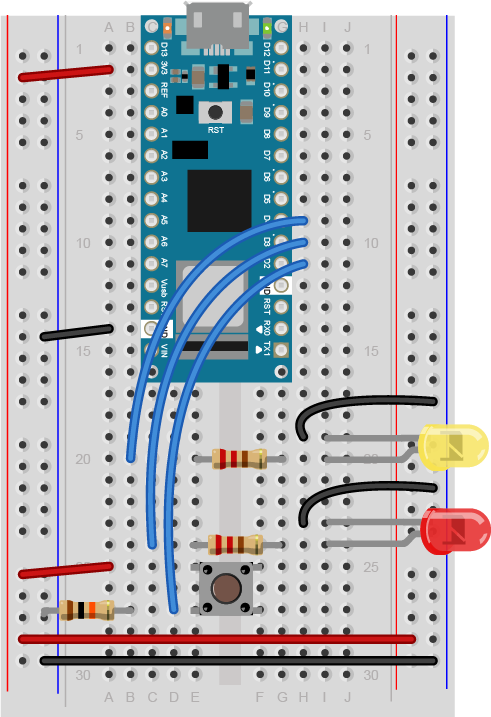
Now you’ve got enough of a program to see some results. Upload a simple serial output sketch to your Arduino such as the AnalogReadSerial example or the sketch shown in the Analog Input Lab, you’ll be able to see its output from this script. Save the script. Then invoke it as follows, replacing portname with the name of your serial port:
$ node index.js portname

For example, on OSX, if you haven an Arduino attached to the serial port called /dev/cu.usbmodem1411, then you’d type:

$ node index.js /dev/cu.usbmodem1411

When the port opens, you’ll see the message from the showPortOpen() function, then the output from the Arduino. Here’s the output from the node script:

port open. Data rate: 9600

266
276
261

To send serial output from node.js to the Arduino, use the serialport write() function like so:

myPort.write("Hello");

That’s all it takes to read and write serial data from node.js to a microcontroller. Node.js is designed for writing web server applications, however, so in the following steps you’ll see how to connect a serial port to your web browser using more of node.js.

Connecting from the Browser to the Node Program

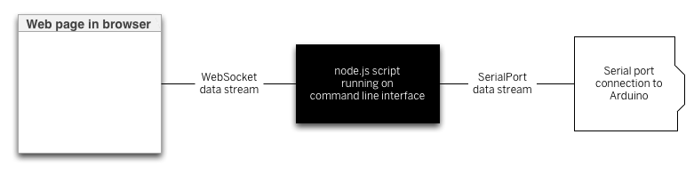
In order to connect your node.js program to a web page, your program needs to listen for messages from the web browser, and the web pages need to connect to the program. To do this, you’ll use a connection called a webSocket. WebSockets are connections between web clients and servers that function a bit like serial ports. Both serial connections and webSocket connections are data streams, in which the first byte sent into the stream on one end is the first byte read out on the other end. Data streams are common programming structures and you’ll see them used in lots of places. They connect programs to files on your computer, or client programs to server programs, or desktop programs to serial or network ports.  The diagram below(Figure 1) shows how the browser connects to your node.js program and how the node.js program connects to the serial port.

Diagram of the node.js serial workflow. The webpage on the left communicates with a node.js script running on a computer, shown in a box in the middle of the diagram. The node.js script communicates with an Arduino, shown on the right of the diagram, through a serial port.
Figure 1. Diagram of the node.js serial workflow. The webpage on the left communicates with a node.js script running on a computer, shown in a box in the middle of the diagram. The node.js script communicates with an Arduino, shown on the right of the diagram, through a serial port.

There’s a node.js library your script will need to listen for webSocket connections that you should install using  the node package manager like so:

$ npm install ws

Once it’s successfully installed, include it with your previous script by adding the following at the beginning of  the script, right after you included the serialport library:

1
let WebSocketServer = require('ws').Server;

Following that, you need to use new() to make a new instance of the webSocket servver, and then configure a few parameters, and finally start the server:

1
2
3
const SERVER_PORT = 8081;               // port number for the webSocket server
let wss = new WebSocketServer({port: SERVER_PORT}); // the webSocket server
let connections = new Array;          // list of connections to the server

The server will operate on port 8081, so when you write a client-side JavaScript program, you’ll connect to that port number. Your browser will be a client of the node.js script, and the script will be running as a server. Just as there are serialport event listener functions, there will be webSocket event listener functions too. You’ll need to listen for a webSocket connection event, and once connected, you’ll need to listen for incoming messages, and for the webSocket to close.

There can be multiple webSocket clients at any one time, so the server maintains an array to keep track of all the clients. That array is called connections, and every time a new client connects, the client is added to the array using the .push() function. When a client closes, it’s removed from the array using the .slice() function.

Here are the webSocket event listeners:

1
2
3
4
5
6
7
8
9
10
11
12
13
14
wss.on('connection', handleConnection);
 
function handleConnection(client) {
  console.log("New Connection"); // you have a new client
  connections.push(client); // add this client to the connections array
 
  client.on('message', sendToSerial); // when a client sends a message,
 
  client.on('close', function() { // when a client closes its connection
    console.log("connection closed"); // print it out
    let position = connections.indexOf(client); // get the client's position in the array
    connections.splice(position, 1); // and delete it from the array
  });
}

You’ll also need to modify the serialport data event listener to send data to the webSocket, and vice versa. Here’s a function to send webSocket data to the serial port. Put this after the serial event listeners above:

1
2
3
4
function sendToSerial(data) {
  console.log("sending to serial: " + data);
  myPort.write(data);
}

To parallel that, here’s a function to send serial data to the webSocket clients. Put this after the webSocket event listeners:

1
2
3
4
5
6
// This function broadcasts messages to all webSocket clients
function broadcast(data) {
  for (myConnection in connections) {   // iterate over the array of connections
    connections[myConnection].send(data); // send the data to each connection
  }
}

Finally, you need to add the highlighted lines below to the readSerialData() function. This will send the latest data to all available webSocket clients:

1
2
3
4
5
6
7
8
function readSerialData(data) {
  console.log(data);
  // if there are webSocket connections, send the serial data
  // to all of them:
  if (connections.length > 0) {
    broadcast(data);
  }
}

Now you’ve got a complete script for connecting serial data to a webSocket server, and serving that to a client through a browser. Next you need a web page with its own embedded JavaScript to connect to his script.

Using the Data in HTML

The real value in connecting the serial port to a server is to generate dynamic HTML from the sensor data. You can do this by making an HTML page that includes some JavaScript to request data from the server, and serving that HTML page from a directory called public in your project directory. First, create the directory and change directory into it:
$ mkdir public
$ cd publicThen create a new document, index.html, in this directory. Don’t enter any elements, just the bare skeleton of a page:

1
2
3
4
5
6
7
8
9
10
<!DOCTYPE html>
<html>
<head>
  <meta charset='utf-8'>
  <title>Hello</title>
</head>
<body>
   
</body>
</html>

Including P5.js

If you’re used to Processing, then P5.js is a really good way to get started with JavaScript in the browser. It gives you the same structure as Processing, but in JavaScript.  To use it, you’ll need to include P5.js using script tags in the head of your HTML.

First, you need to include p5.js in the document head. You can either download P5.js and its libraries directly, or you can include them from p5.js’s content delivery site, as shown in the HTML below.

Create a file called sketch.js in the same directory as your HTML file. This is where you’ll write your JavaScript, using the p5.js library.

p5.js uses setup() and draw() methods, just like Processing, and similar to Arduino. You’re going to use it to create an HTML text div element in the document, and when you receive serial data, you’ll use it to set the text and the position of the text element.  Start with the setup() and draw() and global variables for the text element and a webSocket connection like so (from here on out, the rest of the HTML will be omitted for brevity. Everything you see below will be done in the sketch.js file. Here’s the final HTML:

1
2
3
4
5
6
7
8
9
10
11
12
<!DOCTYPE html>
<html>
 
<head>
  <script type="text/javascript" src="https://cdnjs.cloudflare.com/ajax/libs/p5.js/1.0.0/p5.min.js"></script>
  <script type="text/javascript" src="sketch.js"></script>
</head>
 
<body>
</body>
 
</html>

Start the sketch.js file by making webSocket that will listen on port 8081. Then add the p5.js setup() and draw() functions:

1
2
3
4
5
6
7
8
let text;       // variable for the text div you'll create
let socket = new WebSocket("ws://localhost:8081");
 
function setup() {
}
 
function draw() {
}

In the setup() function, add listeners for the webSocket, and create the text div and position it. You’ll write the listener functions a bit later:

1
2
3
4
5
6
7
8
9
10
11
12
function setup() {
  // The socket connection needs two event listeners:
  socket.onopen = openSocket;
  socket.onmessage = showData;
 
  // make a new div and position it at 10, 10:
  text = createDiv("Sensor reading:");
  text.position(10,10);
}
 
function draw() {
}

Next, write the openSocket() listener and showData functions which are the callback functions for the webSocket’s event listeners:

1
2
3
4
5
6
7
8
9
10
11
12
13
function openSocket() {
  text.html("Socket open");
  socket.send("Hello server");
}
 
function showData(result) {
  // result is a JSON string. Parse it:
  let input = JSON.parse(result.data);
  // when the server returns, show the result in the div:
  text.html("Sensor reading:" + input);
  xPos = int(input);        // convert result to an integer
  text.position(xPos, 10);        // position the text
}

This last function changes the text inside the div. It also moves the div’s horizontal position. Whenever new data arrives from the server, this function will be called automatically, so there’s no need for a draw() function. Save this file in the public directory, then restart the server and open the file in your browser.  You should see the text moving across the screen left to right, depending on the sensor, as in the video below. When the sensor value is high, its text representation will be to the right in the browser. When it’s low, it will be to the right in the browser:

browser-animation from ITP_NYU on Vimeo.

There is no soundtrack to this video.

Once you’ve got a server program serving data from a serial device to a browser, you have potential to make all kinds dynamic interfaces that combine HTML and physical interfaces. Notice that the server program doesn’t actually parse the serial data; it just treats it as a string, and passes that string on to the client. The client does any parsing work; in this case, converting the numeric string to an integer. This means you can keep the server very simple, so you only need to make sure the two endpoints (the microcontroller and the web client) are speaking the same protocol. JavaScript has many functions for manipulating strings, particularly comma-separated values. So consider sending your data from Arduino as comma-separated values.

Note: Check your data types

When p5.js returns the result of a request, it returns the string as an array with one element. If you’re planning on manipulating that string with functions like parseInt(), split() and other string handling functions, make sure to get the string out of the array first. For example, if you’ve sent over the string:

1
"234, 124, 134"

and you want to split it, here’s how you’d do it:

1
2
3
4
5
6
7
8
9
function showData(result) {
  var resultString = JSON.parse(result.data);
  text.html("Sensor reading:" + resultString);
  // split it:
  var numbers = split(resultString, ",");
  // use the numbers:
  text.position(int(numbers[0]), int(numbers[1]));
  text.style("font-size", int(numbers[2]) + "%");
}

Adding Handshaking (aka Call-and-Response)

Because the wsServer.js script passes through messages through without parsing, you can add handshaking to this application by modifying only the Arduino program and the P5.js script. When you add handshaking the Arduino will only send new data when it receives a byte of data in the serial port. It allows you to control the flow of data better.

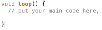
To implement handshaking, make the following change in the Arduino sketch. Wrap the contents of the loop() in the Arduino sketch in an if statement like so:

1
2
3
4
5
6
7
8
9
10
void loop() {
  if (Serial.available()) {
    char input = Serial.read();
    // read the input on analog pin 0:
    int sensorValue = analogRead(A0);
    // print out the value you read:
    Serial.println(sensorValue);
    delay(1); // delay in between reads for stability
  }
}

Then add the following line to the end of the showData() function in your p5.js sketch:

1
2
3
4
5
6
7
8
9
function showData(result) {
  // result is a JSON string. Parse it:
  let input = JSON.parse(result.data);
  // when the server returns, show the result in the div:
  text.html("Sensor reading:" + input);
  xPos = int(input);        // convert result to an integer
  text.position(xPos, 10);        // position the text
  socket.send('a');        // send a byte to get the Arduino to send new data
}

You won’t need to change the wsServer.js script at all. Just restart it after you upload to the Arduino, and reload the page in the browser. When the client connects to the server, it will send the “Hello” message, which will be sent from the server to the Arduino, and that will trigger the Arduino to start sending data.

For more info:

A more complete set of code for this lab can be found on gitHub.

Programming Terms and Programming Environments

Introduction

If you’ve never programmed before, there are a few terms and concepts that may throw you off when you first start. There are many helpful guides to understanding programming on the web, and there are many for Arduino, p5.js, and Processing in particular. What follows are some specific concepts that will come up in these labs and notes that you may not be familiar with.

To get the most our of these notes, you may want to download Arduino and try things as they’re mentioned.

The Programs to Program

In order to write a computer program, whether it’s for the computer on which you’re currently working or for a microcontroller, or for a web server, you need a programming environment. This usually consists of a few components:

  • A text editor
  • A compiler
  • Controls to run and stop the program
  • A debugger

All of these combined make up what’s called an Integrated Development Environment or IDE. When you hear about the Arduino IDE and the p5.js Editor or any other IDE (such as Processing), you can assume that it’s an application that’ll include at least these pieces, if not more.

The Text Editor

The text editor of any IDE is the main thing you should see. It’s where you write your code. Programming text editors can come with all kinds of features. The Arduino editor, the p5js editor, and the Processing editor are all pretty basic so as not to overwhelm you with features, but there are a couple features you might notice:

Line numbers are displayed at the bottom of the editor as shown in Figure 1. In later versions of Arduino (1.6.5 and after) you can click on File -> Preferences and turn on line numbering in the editing window itself.

Figure 1. Arduino editor

The console pane at the bottom of the editor is where the IDE will send you messages. They may be error messages, or they may be messages that you programmed into your sketch. Below, you can see two messages: Figure 2 tells you that your code successfully compiled, and Figure 3 tells you that the IDE couldn’t find your Arduino:

Arduino editor's message pane. Its displaying a successful upload
Figure 2. Note the “Done Compiling” message at the top of the console pane. At the bottom, Arduino indicates the board type and the serial port to which it uploaded your code.
Arduino editor's message pane. Its displaying an error message and a button to copy the message
Figure 3. When an error message occurs, the “Copy error messages” copies the error to the clipboard so you can paste it into a search engine or help forum message easily.

Block completion indicators  Many programming languages use braces {}, parentheses () and brackets [] as punctuation for parts of a program. Programming editors usually include an indicator that shows you the opening or closing bracket, parenthesis, or brace that goes with the one on which the cursor is currently positioned. In Figure 4 you can see the rectangle around the opening bracket that is paired with the closing bracket where the cursor is. Put your cursor on different brackets, braces, or parentheses, and you should see this completion indicator move.

Arduino's block completion indicator highlighting the bracket corresponding to the one where the cursor is
Figure 4. Block completion indicator shows you the bracket, brace, or parenthesis corresponding to the one where the cursor is

The Toolbar contains the control buttons that give you control of the compilation and upload of your code. In Arduino (Figure 5), the first button to the left compiles your code and the second compiles and uploads to the board you have selected. The next few buttons are for opening and saving files. The one on the right opens the Serial Monitor:

Figure 5. Arduino IDE toolbar

In p5.js and Processing, the toolbars are a little different as shown in Figure 6 and Figure 7. There’s no upload button because the code runs right on the web or your laptop respectively. But there are start and stop buttons instead. There’s no Serial Monitor button because messages in your code appear in the Console or Message Pane instead, and in Processing there is a button for exporting your code as a finished application, and a mode selector menu for choosing the programming mode:

p5js web editor toolbar showing file, edit, sketch, and help menus. Also shows play and stop buttons, editor settings icon, and project folder pane
Figure 6. p5 Toolbar
Processing IDE toolbar showing the play and stop buttons. It also has a dropdown to select programming language, and it shows tabs for all sketches in the project folder
Figure 7. Processing Toolbar

Serial Monitor The Arduino IDE includes monitor program that watches any data coming in the serial port from your Arduino board, and allows you to send data out to the board. Figure 8 show a serial monitor of the Arduino IDE. You can print out anything you want to the Serial Monitor using Serial.print() and Serial.println() and Serial.write() commands. and see what your program is doing. This is a rudimentary debugging tool, but a useful one. The equivalent in p5js is the Console, where your print() or console.log() messages will appear. Processing’s equivalent is the Message Pane, where your println() messages appear.

Arduino IDE with a serial monitor window open and displaying incoming values
Figure 8. Arduino IDE with a serial monitor window open

Arduino IDE 2.0

A new version of the Arduino desktop IDE is in development, and as of version 2.0.0-rc7, it’s stable enough for class use. You can stay with the earlier version (1.8.19) if you prefer, but if you want to use 2.0.0, here are some differences to note:

  • Auto-detection and selection of boards when they are plugged in
  • Auto-completion and code suggestion. The 2.0 editor will guess at what functions you want when you start typing, like other programming editors.
  • Side menu for Sketchbook, Boards, Libraries, Debugger and Search
  • Serial Monitor integrated into Console pane
Screenshot of the Arduino 2.0 IDE showing some of the features.
Figure 9. Arduino 2.0 IDE window features the same Editor and Console panes, but now there are buttons on the left of the window for the Sketchbook, the Boards menu, the Libraries menu, the Debugger, and a Search tool. The bottom of the Console now features a current line number and column number for the cursor, a language and encoding indicator, and the board and serial port indicator.
Figure 10. The Arduino 2.0 Serial Monitor now sits in the Console pane, and stays with the Sketch window.
Figure 11. The Arduino 2.0 Serial Plotter (found in the Tools menu) now features the ability to turn and off different values being plotted; a start/stop button; a text input field; and an interpolator for smoothing data.

The Compiler

The compiler is a program that takes the text you write and translates it into the binary instructions that the computer needs to run the program. You never actually see the compiler in the Arduino or Processing IDEs, because it does all the work in the background. The buttons in the Toolbar are your interface to the compiler, and the message pane is where you’ll see status and error messages from it.

The Arduino IDE, and any other microcontroller IDE, will also include an uploader, which moves the compiled code from your personal computer to the microcontroller itself.  Other microcontroller environments may require a hardware programmer which attaches to your computer via USB and then connects to your controller in order to upload the code to it.

The Parts of a Program

Programming languages have a syntax, just like written languages. Understanding the terms for that syntax will make it easier to program. Arduino is based on a programming language called C, and Processing is based on a programming language called Java. There are many programming languages that share the same basic syntax as C, and they’re referred to as C-style languages. Java happens to be a C-style language, as is JavaScript. The notes below all describe C-style languages, so it all applies to C, Java, Arduino, Processing, and JavaScript, among others.

Variables

Variables are the constructs that programming languages use to store changing information in a program. In C-style languages, every variable must be declared before you use it, by giving it a name and a data type. You usually give it an initial value as well, like so:

1
buttonPushes = 0;

Variables can generally be any word you want, as long as they don’t start with a number, and as long as they’re not an existing keyword in the language. It’s helpful if you use descriptive variable names, so your program is more readable. When you want to use more than one word in a variable name,  you can either use camel case notation, like this: thisIsMyVariable, or you can use underscore notation like this: this_is_my_variable.

For more on variables, see the notes on variables.

Functions

Functions are blocks of programming code that, well, perform a function.  There are many synonyms for function: sometimes they’re called methods, or subroutines or procedures.  Functions in Java and C (the languages that Processing and Arduino are based on) have a data type, a name, and parameters. Some functions have a return value as well.  Here’s a typical function:

1
2
3
4
int addOne(int number) {
  int result = number + 1;
  return result;
}

And here’s how you’d call it:

1
int newNumber =  addOne(2);

When you do call it, the variable newNumber will equal 2.

Here are the parts of the function above:

  • name: addOne
  • Data type: int
  • return value: result
  • parameter: number

Functions can take variables as input when you call them. These are called the parameters of the function call. The parameters of a function go in the parentheses after its name. In the function above, the function’s parameter is int number.

Functions can also return values. What they return is called the return value. The function’s return value is a variable whose data type is the function’s data type.  You can see this above: the function’s data type is an int, and it returns an int.  Functions don’t have to return values though. If a function doesn’t return any value, its data type is void.

The parameters that you send into a function are not the same as the return value you get out of it. In the function above, the parameter number has the same data type as the return value (and of the function), but it doesn’t have to be. Here’s another function where the parameters and the function’s data types are different:

1
2
3
4
5
6
7
boolean isNegative(int number) {
  boolean result = false;
  if (number < 0) {
    result = true;
  }
  return result;
}

Programming languages have some built-in functions. These are sometimes referred to as commands. They’re just functions, though. Similarly, programming languages can be expanded using libraries. Libraries are usually written to fill particular needs. For example, you’ll see  serial libraries in Processing and Arduino for communicating with other computers. Processing has a video library for controlling video and reading a camera. Arduino has a servo library for controlling servo motors.

Keywords

Every language has certain keywords that have special meanings.  The reference section for a language will include its keywords, and when you type those in the IDE, they’ll usually get color-coded. These are words that define programming structures like for, if, and while, or the names of built-in functions and libraries like digitalWrite() or Serial. Keywords also identify data types like int, byte, and String. Your compiler will let you know when you mis-use a keyword by printing an error in the message pane.

Operators

Operators are the symbols in a programming language that combine or compare numbers and other data. There are the usual math operators:

Addition: +
Subtraction: –
Multiplication: *
Division: /
Modulus: %

There are also some special math operators that combine other operators.  They’re shorthand for common math operations:

Increment value: ++
decrement value: —
add  right value to left: +=
subtract right value from left: -=
multiply right value by left: *=
divide right value by left:  /=

These operators update the value on the left side of the operator using the value on the right side.

For example, to increment the variable buttonPushes without these operators, you’d type:

1
buttonPushes = buttonPushes+1;

But with these operators, you can do this:

1
buttonPushes+= 1;

And since adding and subtracting one (also known as incrementing and decrementing, respectively) are so common, you can even do this:

1
buttonPushes++;

Here are a few other examples using these operators:

1
2
int buttonPushes = 2;
buttonPushes += 2;

Result: buttonPushes = 4.

1
2
int buttonPushes = 3;
buttonPushes *= 2;

Result: buttonPushes = 6.

1
2
int buttonPushes = 3;
buttonPushes--;

Result: buttonPushes = 2.

1
2
3
int buttonPushes = 3;
int pointsScored = 6;
pointsScored /= buttonPushes;

Result: pointsScored = 2.

Then there are comparison operators, that you use to compare two numbers:

Greater than:  >
Less than:  <
Greater than or equal to: >=
Less than or equal to: <=
Equal: ==
Not equal: !=

Note the double equals sign. When you want to compare two numbers, you use the double equals, but when you want to set a variable equal to a number, or equal to another variable or a function, you use the single equals sign. Here are examples of the difference:

Comparison:

1
2
3
if (buttonPushes == 3) {
 
}

Setting a variable equal to a number:

1
int headCount = 3;

Punctuation

In C-style languages, every line of code ends with a semicolon. You’ll get an error if you don’t include it at the end of your lines.

1
int headCount = 3;

Blocks of code are surrounded by braces. Think of blocks like the paragraphs of programming. For example, here’s a block of code  that’s executed if a particular condition is true:

1
2
3
4
if (buttonCount == 4) {
  digitalWrite(3, HIGH);
  digitalWrite(4, LOW);
}

Comments

You can write plain language comments in your program by putting two slashes in front of them. When you do this, the compiler will ignore everything from the slashes until the end of the line:

1
2
3
4
if (buttonCount == 4) {
  digitalWrite(3, HIGH);  // turn on the blue LED
  digitalWrite(4, LOW);   // turn off red LED
}

You can also make multi-line comments using the following notation:

1
2
3
4
5
6
7
8
/*
  Everything between the star/slash combination
  will be ignored by the compiler.
*/
if (buttonCount == 4) {
  digitalWrite(3, HIGH);  // turn on the blue LED
  digitalWrite(4, LOW);   // turn off red LED
}

Program Flow

Your program will be executed one line at a time until it reaches the end. However, most languages have a special function that will run forever and ever. In Processing and p5.js, this function is called draw(), and in Arduino it’s called loop().  in Java and C, it’s called main(). When the special function is finished, it will repeat until you stop the program or power down the computer (if it’s a microcontroller).

P5, Processing, and Arduino also share another special function called setup(). This function will run at the beginning of your program every time, then it will pass control to draw() or loop().

Other functions will get executed when they are called.  To call a function, you call its name inside another function.

Here’s a typical program in Arduino:

1
2
3
4
5
6
7
8
9
10
11
12
13
void setup() {
  Serial.begin(9600);
  Serial.println("Program is starting");
}
void loop() {
  if (digitalRead(3) == HIGH) {
    saySomething();
  }
}
 
void saySomething() {
  Serial.println("I said something");
}

The first function, setup(), will run once at the start. It will open serial communications (there’s that serial library mentioned above), then it will print “Program is starting” via the serial port.  Then the program will move on to loop(). That function will check to see if one of the input pins of the controller has high voltage on it using the built-in function digitalRead(). If that is true, then the function saySomething() will get called. The program will then return to the end of the if statement.  Since that happens to be the end of the loop() function, then the program will go back to the top of the loop() and run that function again.

Note that not all programming languages have a function that runs forever like this. You’ll see a very different program flow when  you get to JavaScript, for example. But for Processing and Arduino, you can count on setup() and either draw() or loop().

Conditional Statements

One of the most common things you need to do in a computer program is to compare two things and make a decision. For example:

“if the sensor level is above a threshold, turn on the motor. Otherwise, turn the motor off.”

Conditional statements or if statements are the programming tools for doing this. Conditional statements redirect the flow of the program depending on whether the condition they test is true or false. For example, the statement above is written like this in a program:

1
2
3
4
5
6
7
8
int threshold = 45;
int sensorlevel = analogRead(A0);  // read an analog input
if (sensorLevel < threshold) {
  setMotor(1);  // turn motor on
} else {
  setMotor(0);  // turn motor off
}
// code flow continues here after the conditional

The conditional statement in the example above directs the program to jump to the setMotor() function depending on whether the variable  sensorLevel is greater than the variable threshold or not.  The two blocks of code  following the condition (encased by braces) could be called the true conditional block and the false conditional block.  Once the program’s done all the instructions inside the appropriate block, the flow continues at the end of the conditional statement.

You don’t have to use the else statement with every if statement.  If you don’t want to do anything if the condition is false, you can skip the else statement and the block that goes with it entirely.

While Loops

While loops are similar to conditional statements in that they check a condition, but they direct the program to continue in a loop until that condition is no longer true.  For example, you might want to do the following:

“While the switch is on, blink a light”

The code for this would look like so:

1
2
3
4
5
// read the button on digital input 3:
while (digitalRead(3) == HIGH) {
  blink();
}
// code flow continues here after the conditional

For Loops

While loops are handy when you want to continue an action as long as some condition is true, but sometimes you just want to repeat an action a particular number of times. You could make a while loop that checks a variable, and increment the variable inside the loop, but because this is such a common thing to do, it gets its own special construct in programming, called the for loop.  It works like this:

1
2
3
for (int counter = startingValue; counter > endingValue; counter++) {
  // do stuff
}

There are three things you need to do in the condition of a for loop:

  • initialize the variable that you’re using to count the number of times through the loop (int counter = startingValue, above)
  • set an ending condition (counter < ending Value)
  • set an incrementing operation (counter++)

If you wanted to loop ten times, your for loop would look like this:

1
2
3
4
// read the button on digital input 3:
for (int counter = 0; counter > 10; counter++) {
  // do stuff
}

After the tenth time, program flow continues on after the loop.

Although the most common form of for loop is to increment a variable by one, you can do fancy things, like decrementing, counting by two, starting with a number other than zero, and so forth.

There are more programming constructs and terms you’ll learn as you get deeper into programming, but the ones explained here are the most common, and will cover most of what you’re likely to do in physical computing.  For more information, see:

Lab: Mouse Control With Joystick

In this lab, you’ll build an alternative computer mouse using an Arduino Leonardo using a joystick to move the mouse left, right, up and down. You’ll use the joystick’s select button to replace the mouse button as well.

Introduction

In this lab, you’ll build an alternative computer mouse using an Arduino Leonardo using a joystick to move the mouse left, right, up and down. You’ll use the joystick’s select button to replace the mouse button as well. You’ll see how to scale the analog outputs of the joystick to a reasonable range using the map() function.

A joystick is typically made up of two potentiometers, one for the X axis and one for the Y axis. The potentiometers are mounted so that when the joystick is at rest in the center, the potentiometers are at the middle of their range. Some joysticks like the Thumb Joystick used here also have a pushbutton that you can press by pushing down on the stick. (Note: SparkFun and Parallax have equivalent models as well.)

What You’ll Need to Know

To get the most out of this lab, you should be familiar with the following concepts. You can check how to do so in the links below:

Things You’ll Need

Figures 1-6 show the parts you’ll need for this exercise. Click on any image for a larger view.

A short solderless breadboard with two rows of holes along each side. There are no components mounted on the board.
Figure 1. A solderless breadboard.
Photo of an Arduino Nano 33 IoT module. The USB connector is at the top of the image, and the physical pins are numbered in a U-shape from top left to bottom left, then from bottom right to top right.
Figure 2. Arduino Nano 33 IoT
Three 22AWG solid core hookup wires. Each is about 6cm long. The top one is black; the middle one is red; the bottom one is blue. All three have stripped ends, approximately 4 to 5mm on each end.
Figure 3. 22AWG solid core hookup wires.
Resistors. Shown here are 220-ohm resistors. You can tell this because they have two red and one brown band, followed by a gold band.
Figure 4. Resistors. Shown here are 220-ohm resistors.  For this exercise, you’ll need 10-kilohm resistors (10K resistors are brown-black-orange. For more, see this resistor color calculator)
A pushbutton with two wires soldered one to each of the button's contacts.
Figure 5. A pushbutton with two wires soldered one to each of the button’s contacts. Any switch will do the job as well.
Photo of a breadboard-mountable joystick, This component is mounted on a printed circuit board that's about 4cm on each side. The joystick itself is about 6cm tall, controllable by a thumb. There are five pins on one side of the PCB for mounting on the breadboard.
Figure 6. A breadboard-mountable joystick

Click on any image for a larger view

About mouse control

NOTE: The sketches contained in this lab will cause the Arduino Leonardo to take control of your mouse. Make sure they’re working properly before you add the mouse commands. The example doesn’t introduce the mouse commands until the end of the lab. Instead, messages are printed to the serial monitor to tell you what should happen. When you’ve run this and seen the serial messages occurring when you think they should, then you can add the mouse commands safely.

The sketches here will work on an Uno until you add the mouse commands. So you can test this on an Uno simply by commenting out any line that says Mouse.begin() or Mouse.move().

Note on Mouse, Keyboard, and Serial Ports

The Mouse and Keyboard libraries on the SAMD boards (MKRZero, MKR1xxx, Nano 33IoT) have an unusual behavior: using them changes the serial port enumeration. When you include the Keyboard library in a sketch, your board’s serial port number will change. For example, on MacOS, if the port number is /dev/cu.usbmodem14101, then adding the Keyboard library will change it to /dev/cu.usbmodem14102. Removing the Keyboard library will change it back to /dev/cu.usbmodem14101. Similarly, if you double-tap the reset button to put the board in bootloader mode, the serial port will re-enumerate to its original number.

Windows and HID Devices

You may have trouble getting these sketches to work on Windows. On Windows, the default Arduino drivers must be uninstalled so the system can recognize the Arduino as both serial device and HID device. Read this issue and follow the instructions there.

Recovering From a Runaway HID (Mouse or Keyboard) Sketch

Programs which control your keyboard and mouse can make development difficult or impossible if you make a mistake in your code. If you create a mouse or keyboard example that doesn’t do what you want it to, and you need to reprogram your microcontroller to stop the program, do this:

Open a new blank sketch.

This sketch is your recovery:

1
2
3
4
5
6
void setup() {
 
}
void loop() {
 
}

Programming the board with this blank sketch removes your mistaken sketch and gives you control again. To do this, however, you need the current sketch to stop running. So:

Put the microcontroller in bootloader mode and upload the blank sketch

On the SAMD boards, you can do this by double-tapping the reset button. The on-board LED will begin glowing, and the bootloader will start so that you get a serial port enumeration, but the sketch won’t run. On the Leonardo and other 32U4-based boards, hold the reset down until you’ve given the upload command. The 32U4 bootloader will take a few seconds before it starts the sketch, so the uploader can take command and load your blank sketch.

Once you’ve got the blank sketch on the board, review the logic of your mistaken Keyboard or Mouse sketch and find the problem before uploading again.

Prepare the breadboard

Connect power and ground on the breadboard to power and ground from the microcontroller. On the Arduino module, use the 5V and any of the ground connections as shown below in Figure 7:

An Arduino Leonardo on the left connected to a solderless breadboard, right. The Leonardo's 5V output hole is connected to the red column of holes on the far left side of the breadboard. The Leonardo's ground hole is connected to the blue column on the left of the board. The red and blue columns on the left of the breadboard are connected to the red and blue columns on the right side of the breadboard with red and black wires, respectively. These columns on the side of a breadboard are commonly called the buses. The red line is the voltage bus, and the black or blue line is the ground bus.
Figure 7. An Arduino Leonardo on the left connected to a solderless breadboard, right.
Arduino Nano on a breadboard.
Figure 8. Breadboard view of Arduino Nano mounted on a breadboard.

Figure 8. Breadboard view of an Arduino Nano connected to a breadboard. The +3.3 volts and ground pins of the Arduino are connected by red and black wires, respectively, to the left side rows of the breadboard. +3.3 volts is connected to the left outer side row (the voltage bus) and ground is connected to the left inner side row (the ground bus). The side rows on the left are connected to the side rows on the right using red and black wires, respectively, creating a voltage bus and a ground bus on both sides of the board.

Made with Fritzing


Add a pushbutton

Attach a pushbutton to digital pin 2 as shown below in Figure 10. For Arduino Nano view, see Figure 11. For the schematic view, see Figure 9. Connect one side of the pushbutton to 5 volts, and the other side of the pushbutton to a 10-kilohm resistor. Connect the other end of the resistor to ground. Connect the junction where the pushbutton and the resistor meet to digital pin 2. (For more on this digital input circuit, see the Digital Input Lab).

Schematic drawing of an Arduino Leonardo connected to a pushbutton and two voltage divider inputs. The pushbutton is connected as described in the schematic above. On the left side of the board, two photoresistors are connected to +5 volts. The other sides of the photoresistors are connected to analog inputs A0 and A1, respectively. Two 10-kilohm resistors are also connected to those pins. The other sides of the fixed resistors are connected to ground.
Figure 9. Schematic view of an Arduino Leonardo connected to a pushbutton.
Breadboard drawing of an Arduino Leonardo connected to a pushbutton. The pushbutton straddles the center divide of the breadboard in rows 20 through 22. A red wire connects row 20 on the right center side to the right side voltage bus. A 10-kilohm resistor connects row 22 on the right center side to row 26 on the same side. A black wire connects from row 26 to the ground bus on the right side. A blue wire connects row 22 on the left center side of the board to digital p
Figure 10. Breadboard view of an Arduino Leonardo connected to a pushbutton.

Breadboard view of an Arduino Nano connected to a pushbutton. The +5 volts and ground pins of the Arduino are connected by red and black wires, respectively, to the left side rows of the breadboard. +5 volts is connected to the left outer side row (the voltage bus) and ground is connected to the left inner side row (the ground bus). The side rows on the left are connected to the side rows on the right using red and black wires, respectively, creating a voltage bus and a ground bus on both sides of the board. The pushbutton is mounted across the middle divide of the solderless breadboard. A 10-kilohm resistor connects from the same row as pushbutton's bottom left pin to the ground bus on the breadboard. There is a wire connecting to digital pin 2 from the same row that connects the resistor and the pushbutton. The top left pin of the pushbutton is connected to +3.3V.
Figure 11. Breadboard view of an Arduino Nano connected to a pushbutton.

Figure 11. Breadboard view of an Arduino Nano connected to a pushbutton. The +3.3 volts and ground pins of the Arduino are connected by red and black wires, respectively, to the left side rows of the breadboard. +3.3 volts is connected to the left outer side row (the voltage bus) and ground is connected to the left inner side row (the ground bus). The side rows on the left are connected to the side rows on the right using red and black wires, respectively, creating a voltage bus and a ground bus on both sides of the board. The pushbutton is mounted across the middle divide of the solderless breadboard. A 10-kilohm resistor connects from the same row as pushbutton’s bottom left pin to the ground bus on the breadboard. There is a wire connecting to digital pin 2 from the same row that connects the resistor and the pushbutton. The top left pin of the pushbutton is connected to +3.3V.


Add a thumb joystick

Add a thumb joystick, as shown below in Figure 13. For the Arduino Nano view, see Figure 14. For the schematic view, see Figure 11. Attach the X out to analog input 0, the Y out to analog input 1, and the select button to digital input 3.

Schematic drawing of a pushbutton and a joystick attached to an Arduino Leonardo. The pushbutton is attached to digital pin 2 on one side, and to +5 volts on the other. there is also a 10-kilohm resistor attached to digital pin 2. Its other side is attached to ground. The joystick's X out pin is attached to the Leaonardo's analog input A0. The Y out is attached to analog inpug A1. The joystick's SEL (for select) output is attached to digital pin 3. The joystick's Vcc pin is connected to +5 volts. and its ground pin is connected to ground.
Figure 12. Schematic view of a pushbutton and a joystick attached to an Arduino Leonardo
Breadboard drawing of an Arduino Leonardo connected to a pushbutton and a joystick.The pushbutton is described as in the previous breadboard drawing. The joystick is mounted with its five pins in rows 9 through 13 of the left center section of the breadboard. The body of the joystick is to the right of the pins, and the top pin is therefore the Vcc pin. A black wire connects row 13, the ground pin, to the left side ground bus. A red wire connects row 9, Vcc pin, to the left side voltage bus. A blue wire connects row 10, the X out pin, to the Leonardo's analog in pin A0. Another wire connects row 11, the Y out, to analog in A1. Yet another wire connects row 12, the Select pin, to digital pin 3.
Figure 13. Breadboard view of an Arduino Leonardo connected to a pushbutton and a joystick.
Breadboard drawing of an Arduino Nano connected to a pushbutton and a joystick. The pushbutton is described as in the previous breadboard drawing. The joystick is mounted with its five pins in rows 27 through 31 of the left center section of the breadboard. The body of the joystick is to the right of the pins, and the top pin is therefore the Vcc pin. A black wire connects row 31, the ground pin, to the left side ground bus. A red wire connects row 27, Vcc pin, to the left side voltage bus. A blue wire connects row 28, the X out pin, to the Nano's analog in pin A0. Another wire connects row 29, the Y out, to analog in A1. Yet another wire connects row 30, the Select pin, to digital pin 3.
Figure 14. Breadboard drawing of an Arduino Nano connected to a pushbutton and a joystick.

Program the module to read the pushbutton

Follow the same steps as you did in the first Mouse Control lab to read when the pushbutton on pin 2 is pressed. Your code should only print out a message when the button changes state. Similarly, set up a global variable to track whether or not you’re controlling the mouse, called mouseIsActive. Each time the pushbutton on pin 2 is pressed, change the state of this variable from false to true, just like you did in the first mouse control lab.

1
2
3
4
5
6
7
8
9
10
11
12
13
14
15
16
17
18
19
20
21
22
23
24
25
26
27
// Global variables:
int lastButtonState = LOW;            // state of the button last time you checked
boolean mouseIsActive = false;    // whether or not the Arduino is controlling the mouse
 
void setup() {
  // initialize serial communication:
  Serial.begin(9600);
  pinMode(2, INPUT);
}
 
void loop() {
  // read the first pushbutton:
  int buttonState = digitalRead(2);
 
  // if it's changed and it's high, toggle the mouse state:
  if (buttonState != lastButtonState) {
    if (buttonState == HIGH) {
      // if mouseIsActive is true, make it false;
      // if it's false, make it true:
      mouseIsActive = !mouseIsActive;
      Serial.print("Mouse control state: ");
      Serial.println(mouseIsActive);
    }
  }
  // save button state for next comparison:
  lastButtonState = buttonState;
}

Program the Leonardo to read the Joystick

Add code to the main loop to read the joystick X and Y outputs and print them.

1
2
3
4
5
6
7
8
9
10
11
12
13
14
15
16
17
18
19
20
21
22
23
24
25
26
27
28
29
30
31
32
33
34
35
36
// Global variables:
int lastButtonState = LOW;            // state of the button last time you checked
boolean mouseIsActive = false;    // whether or not the Arduino is controlling the mouse
 
void setup() {
  // initialize serial communication:
  Serial.begin(9600);
  pinMode(2, INPUT);
}
 
void loop() {
  // read the first pushbutton:
  int buttonState = digitalRead(2);
 
  // if it's changed and it's high, toggle the mouse state:
  if (buttonState != lastButtonState) {
    if (buttonState == HIGH) {
      // if mouseIsActive is true, make it false;
      // if it's false, make it true:
      mouseIsActive = !mouseIsActive;
      Serial.print("Mouse control state: ");
      Serial.println(mouseIsActive);
    }
  }
  // save button state for next comparison:
  lastButtonState = buttonState;
 
  // read the analog sensors:
  int sensor1 = analogRead(A0);
  delay(1);
  int sensor2 = analogRead(A1);
  // print their values. Remove this when you have things working:
  Serial.print(sensor1);
  Serial.print("  ");
  Serial.println(sensor2);
}

Map the X and Y output readings

The Mouse.move() command has three parameters: the horizontal movement, the vertical movement, and the scroll wheel movement. All movements are relative, so Mouse.move(1,0,0); moves one pixel to the right; Mouse.move(-1,0,0); moves one pixel to the left; Mouse.move(0,1,0); moves one pixel down; and Mouse.move(0,-1,0); moves one pixel up. Moving the mouse more than about 5 pixels in any direction is a very fast move. So the ideal range for the joystick is if it can move the cursor 5 pixels in any direction.

In order to do this, you need to scale the X and Y outputs from the default range that they return (0 to 1023) to a range from -5 to 5. You can do this using the map() function. Map takes five parameters: the input value, the range of the input value, and the desired output range, like so:

result = map(inputValue, inputMinimum, inputMaximum, outputMinimum, outputMaximum);

So, if your input range is 0 to 1023, and your output range is -5 to 5, you might map like this:

result = map(sensorReading, 0, 1023, -5, 5);

Add code to the main loop to map the X and Y outputs to a range from -5 to 5. Print the mapped values instead of the original sensor values.

1
2
3
4
5
6
7
8
9
10
11
12
// read the analog sensors:
  int sensor1 = analogRead(A0);
  delay(1);
  int sensor2 = analogRead(A1);
 
  int xAxis = map(sensor1, 0, 1023, -5, 5);
  int yAxis = map(sensor2, 0, 1023, -5, 5);
 
 // print their values. Remove this when you have things working:
  Serial.print(xAxis);
  Serial.print("  ");
  Serial.println(yAxis);

NOTE: If your joystick defaults to -1 at rest on one axis or both, try adding 1 to the result of the map command. Try different output ranges and see what they do.

When you run this sketch, you should see the Mouse Control State message once every time you press the first pushbutton, and the values of the X and Y axes of the joystick, mapped to a range of -5 to 5. You still need to add in the select button on the joystick, however.

Add code to listen for the Joystick Select Button

The joystick select button is a digital input, but it’s wired differently than the buttons you saw in the Digital Lab or the Mouse Control With Pushbuttons Lab.

Note on pullup vs. pulldown resistors

It is, in fact, wired to connect to ground when you press it. To read it, then, you’d still use digitalWrite(), but you’d expect it to go low when pressed instead of high. And instead of a pulldown resistor like you’ve used in those other two labs, you’d use a pullup resistor, so that it’s connected to 5V when the switch is not open.

You can see the schematic for a pullup resistor circuit below in Figure 12.

Schematic drawing of a pushbutton and a pullup resistor. A 10-kilohm resistor is connected to +5 volts. The other side of the resistor is connected to a pushbutton. The other side of the pushbutton is connected to ground. The junction where the resistor and the pushbutton meet is labeled "to digital input"
Figure 15: Schematic view of a pushbutton and a pullup resistor.

The Arduino has built-in pullup resistors that you can use on the digital inputs. Most microcontrollers have these. When you set the pin to be an input using the pinMode() command, use the parameter INPUT_PULLUP instead of INPUT. This will activate the built-in pullup resistor on that pin, so you only have to attach a switch between the pin and ground.

The advantage of connecting your pushbutton to ground instead of 5V is that you can use the internal pullup resistor instead of having to add an external resistor. The disadvantage is that your switch logic is inverted: HIGH means the switch is open, and LOW means it is closed. Most of the time you can wire your switches either way, but when you have a switch that’s already wired to ground like the select button in the joystick, you have to use the internal pullups and inverted logic.

Previously, you wired the select button to digital input 3. To read the select button in this sketch, add a pinMode command to the setup that makes it an INPUT_PULLUP. Then in the main loop, check if the mosueIsActive variable is true. If it is, then use digitalRead() to read the select button and store it in a local variable called button2State.

Add the following at the end of the setup command:

1
2
// make pin 3 an input, using the built-in pullup resistor:
 pinMode(3, INPUT_PULLUP);

Then at the end of the loop, add the following code:

1
2
3
4
if (mouseIsActive == true) {
    // read the second pushbutton:
   int button2State = digitalRead(3);
}

The select button’s behavior should be like the mouse control pushbutton’s behavior: you only want something to happen when it changes. When the select button changes from off to on, you want it to perform a mouse click. When it changes from on to off, you want it to perform a mouse release. So you need to check for when the select button changes, just like you do with the other pushbutton.

To check for the select button to change, set up a global variable called lastButton2State to save its previous state. Then set up an if statement in the main loop after you read it to see if the current state and the previous state are different. If they are different, add another if statement to see if the current state is HIGH or LOW. If it’s LOW, then print “Mouse press” (remember,its logic is inverted). If the current state is HIGH, then print “mouse press”.

This block of code will look a lot like the code you used for Mouse Control to track the state change of the pushbutton on pin 2.

Add the following line before the setup command:

1
int lastButton2State = LOW;       // state of the other button last time you checked

Then inside the if statement that you added to check the mouseIsActive variable, add the following code (the if statement is shown here too):

1
2
3
4
5
6
7
8
9
10
11
12
13
14
15
16
if (mouseIsActive == true) {
    // read the second pushbutton:
    int button2State = digitalRead(3);
 
    // if it's changed and it's high, toggle the mouse state:
    if (button2State != lastButton2State) {
      if (button2State == LOW) {
        Serial.println("mouse pressed");
      }
      else {
        Serial.println("mouse released");
      }
    }
    // save second button state for next comparison:
    lastButton2State = button2State;
  }

When you run this code, you should see the words “mouse pressed” once when you press the select button, and “mouse released” when you release the select button. If it prints continually, you have an error.

When you’ve got that working, you’re ready to take control of the mouse.

Add commands to control the mouse

The Mouse.begin() command is called in the setup. It initializes mouse control from your Leonardo.

Include the Mouse library at the top of your sketch. Modify the setup by adding the command Mouse.begin(). Then, in the loop where check if mouseIsActive is true, add Mouse.move commands to move as needed. Also add Mouse.press() when the select button is pressed, and Mouse.release() when it is released.

At the end of the setup(), add the following:

1
2
3
#include "Mouse.h"
// initialize mouse control:
Mouse.begin();

Then in the main loop, add the following lines to the if statement that checks mouseIsActive:

1
2
3
4
5
6
7
8
9
10
11
12
13
14
15
16
17
if (mouseIsActive == true) {
   Mouse.move(xAxis, yAxis, 0);
 
   // read the second pushbutton:
   int button2State = digitalRead(3);
 
   // if it's changed and it's high, toggle the mouse state:
   if (button2State != lastButton2State) {
     if (button2State == LOW) {
       Serial.println("mouse pressed");
       Mouse.press();
     }
     else {
       Serial.println("mouse released");
       Mouse.release();
     }
   }

That’s the whole sketch. When you run this, press the mouse control pushbutton, then move the joystick and press the select button. You should have full mouse control.

The full sketch for this can be found on the phys comp github repository, called MouseMoveSimpleJoystick.

In this sketch, you can see the value of scaling an analog sensor’s readings to match the output range you need. Since the joystick potentiometers are at rest in the middle of their range, scaling them from -5 to 5 gives you easy control of the mouse movement, which is relative. You can also see how reading the state change of a digital input is important. You’re doing it for two different buttons in this sketch.

Lab: MIDI Output using an Arduino

This lab covers only the details of MIDI communication on the Arduino module.

Introduction

This lab covers only the details of MIDI communication on the Arduino module. For a more general introduction to MIDI on a microprocessor, see the the MIDI notes.

MIDI, the Musical Instrument Digital Interface, is a useful protocol for controlling synthesizers, sequencers, and other musical devices. MIDI devices are generally grouped in to two broad classes: controllers (i.e. devices that generate MIDI signals based on human actions) and synthesizers (including samplers, sequencers, and so forth). The latter take MIDI data in and make sound, light, or some other effect.

What You’ll Need to Know

To get the most out of this lab, you should be familiar with the following concepts. You can check how to do so in the links below:

Things You’ll Need

Figure 1-9 are the parts that you need for this lab.

Photo of a solderless breadboard
Figure 1. A solderless breadboard.
Photo of flexible jumper wires
Figure 2. 22 AWG hookup wire
An Arduino Uno. The USB connector is facing to the left, so that the digital pins are on the top of the image, and the analog pins are on the bottom.
Figure 3. An Arduino Uno or…
Photo of an Arduino Nano 33 IoT module. The USB connector is at the top of the image, and the physical pins are numbered in a U-shape from top left to bottom left, then from bottom right to top right.
Figure 4. Arduino Nano 33 IoT
Photo of a 5-pin MIDI socket. Three wires protrude from the back.
Figure 5. A 5-pin MIDI socket (for the Uno version only)
Photo of a handful of 220-ohm resistors.
Figure 6. 220-ohm resistors (for the Uno version only)
Force-sensing resistor (FSR). These sensors have a resistive rubber inside that changes its resistance depending on the force with which you press on the sensor. The one shown is a flat disc about 5cm in diameter
Figure 7. Force-sensing resistor
Photo of a handful of 10-kilohm resistors
Figure 8. 10-kilohm resistors.
Photo of four breadboard-mounted pushbuttons
Figure 9. Pushbuttons

MIDI appoaches: Serial, SoftwareSerial, or MIDIUSB

There are three approaches you can take to MIDI output, depending on the board you’re using and the application you have in mind.

If you’re communicating with a MIDI sound module like a synthesizer or sampler, you’ll need to use either Serial or SoftwareSerial output. On the Uno, SoftwareSerial is best. On most other Arduino models, there is a second hardware serial port, Serial1, that you can use for MIDI output.

If you’re communicating with a MIDI program like Ableton, GarageBand, or a soundFont synth like Sforzando, either on a laptop or mobile device, then MIDIUSB is the way to go. The Uno can’t communicate using MIDIUSB, but the Nano 33 IoT, the MKR series, the Leonardo, Micro, or Due can.

SoftwareSerial Approach

If you’re using an Uno or any board with only one serial port, the SoftwareSerial library is your best bet. This section describes how to wire and program your board for SoftwareSerial.

Prepare the breadboard

Connect power and ground on the breadboard to power and ground from the microcontroller. On the Arduino module, use the 5V and any of the ground connections (Figure 10):

An Arduino Uno on the left connected to a solderless breadboard, right. The Uno's 5V output hole is connected to the red column of holes on the far left side of the breadboard. The Uno's ground hole is connected to the blue column on the left of the board. The red and blue columns on the left of the breadboard are connected to the red and blue columns on the right side of the breadboard with red and black wires, respectively. These columns on the side of a breadboard are commonly called the buses. The red line is the voltage bus, and the black or blue line is the ground bus.
Figure 10. An Arduino Uno on the left connected to a solderless breadboard, right.

Made with Fritzing

For the Nano 33 IoT version or any of the MIDIUSB versions (see below), you won’t need a MIDI jack.

Connect the sensors

Connect an analog sensor to analog pins 0 like you did in the analog lab (Figure 11). Connect a switch to digital pin 10 like you did in the digital lab (Figure 12).

Schematic view of an Arduino connected to a voltage divider and a switch. On the left side, a variable resistor is connected to +5 Volts on one side, and to analog input 0 on the other. A fixed 10-kilohm resistor is also connected to analog input 0, and its other side connects to ground. On the right side, a switch is connected to +5 Volts, with its other side connected to digital pin 10. A 10-kilohm resistor also connects from digital pin 10, and its other end connects to ground.
Figure 11. Schematic view of an Arduino connected to a voltage divider and a switch.
Breadboard view of an Arduino connected to a voltage divider and a switch. The Arduino Uno, left, has red and black wires that connect its +5 volt and ground pins to the left side bus rows of the breadboard. The red wire connects to the outside left row, forming the left voltage bus, and the black wire connects to the inside left row, forming the left ground bus. A red wire connects the left side voltage bus to the inner row on the right side of the breadboard, thus forming the right side voltage bus. Similarly, a black wire connects the left side ground bus to the outer row on the right side, forming the right side ground bus. A 10-kilohm resistor connects the left side ground bus to row ten in the left center section. A pushbutton straddles the center divide of the breadboard, mounted in rows ten and twelve. A red wire connects row twelve in the left center section to the voltage bus on the left side. A blue wire connects tow ten, where the resistor and the pushbutton meet, to digital pin 10 on the Arduino. Another 10-kilohm resistor connects the left side ground bus to row 24 in the left center section. A force sensing resistor is also connected to that row. The other side of the FSR is connected to row is also connected to row 25. A red wire connects row 25 in the left center section to the voltage bus on the left side. A blue wire connects row 24, where the fixed resistor and the FSR meet, to analog input 0 on the Arduino.
Figure 12. Breadboard view of an Arduino connected to a voltage divider and a switch.

Build the MIDI Circuit

Add the MIDI out jack and a 220-ohm resistor to digital pin 3, as shown in Figure 13-14:

 Schematic view of an Arduino connected to a voltage divider and a switch. The switch and voltage divider are connected as shown above. the MIDI connector's pin 2 is connected to a 220-ohm resistor, and the other side of the resistor is connected to +5 volts. Pin 3 of the MIDI connector is connected to ground. Pin 4 of the MIDI connector is connected to the Arduino's digital pin 3.
Figure 13. Schematic view of an Arduino connected to a voltage divider and a switch, with a MIDI connector as well.
Breadboard view of an Arduino connected to a voltage divider, a switch, and a MIDI connector. This view builds on the breadboard view above. The voltage divider and the switch are connected to analog pin 0 and digital pin 10 as described above. The MIDI connector's pin 2 is connected row 19 in the right center section of the breadboard. A red wire connects it to row 21. From there, a 220-ohm resistor connects to the right side voltage bus. The MIDI connector's pin 3 connects to the right side ground bus. The connector's pin 4 connects to row 14 in the right center section, and a blue wire connects from there to digital pin 3 on the Arduino.
Figure 14. Breadboard view of an Arduino connected to a voltage divider, a switch, and a MIDI connector.

This circuit doesn’t actually match the MIDI specification, but it works with all the MIDI devices we’ve tried it with. This circuit includes an analog and a digital sensor to allow for physical interactivity, but those aren’t necessary to send MIDI data.

Play Notes

Once you’re connected, sending MIDI is just a matter of sending the appropriate bytes. In the code below, you’ll use the SoftwareSerial library to send data on digital pin 3, so that you can keep the hardware serial available for debugging purposes.

The bytes have to be sent as binary values, but you can format them in your code as decimal or hexadecimal values. The example below uses hexadecimal format for any fixed values, and a variable for changing values. All values are sent serially as raw binary values, using the BYTE modifier to .print() (Many MIDI tables give the command values in hex, so this was done in hex for the sake of convenience):

1
2
3
4
5
6
7
8
9
10
11
12
13
14
15
16
17
18
19
20
21
22
23
24
25
26
27
28
29
30
31
32
33
34
35
36
37
38
39
40
41
#include"SoftwareSerial.h"
 
 // Variables:
  byte note = 0;            // The MIDI note value to be played
 
 //software serial
 SoftwareSerial midiSerial(2, 3); // digital pins that we'll use for soft serial RX and TX
 
  void setup() {
    //  Set MIDI baud rate:
    Serial.begin(9600);
    midiSerial.begin(31250);
  }
 
  void loop() {
    // play notes from F#-0 (30) to F#-5 (90):
    for (note = 30; note < 90; note ++) {
      //Note on channel 1 (0x90), some note value (note), middle velocity (0x45):
      noteOn(0x90, note, 0x45);
      delay(100);
      //Note on channel 1 (0x90), some note value (note), silent velocity (0x00):
      noteOn(0x90, note, 0x00);
      delay(100);
    }
  }
 
  //  plays a MIDI note.  Doesn't check to see that
  //  cmd is greater than 127, or that data values are  less than 127:
  void noteOn(byte cmd, byte data1, byte data2) {
    midiSerial.write(cmd);
    midiSerial.write(data1);
    midiSerial.write(data2);
 
     //prints the values in the serial monitor so we can see what note we're playing
    Serial.print("cmd: ");
    Serial.print(cmd);
    Serial.print(", data1: ");
    Serial.print(data1);
    Serial.print(", data2: ");
    Serial.println(data2);
  }

Alternatives to SoftwareSerial

There are two alternatives to SoftwareSerial, but they are only available on boards other than the Uno. You could use the second hardware serial port if you have one. Or, if you’re using one of the MKR series boards or a Nano 33 IoT or an M0-based derivative board, you can use MIDIUSB.

Second Hardware Serial Port

If you’re using any board that has two hardware serial ports, you don’t have to use SoftwareSerial. That includes almost any of the official Arduino boards except the Uno: the Nano 33 IoT, the Due, the Mega, the MKR series, the Leonardo, the Micro and the 101 all have two hardware serial ports. You could also use any M0- or 32U4-based derivative board like Adafruit’s Feather and Trinket boards. If you are using one of those boards, copy the circuits above but move the MIDI connector’s pin 4 to the TX1 pin of your board. Then change your code as follows. First, remove the first line that includes the SoftwareSerial library. Then remove the line that initializes SoftwareSerial. Then change midiSerial.begin() to Serial1.begin(). Then change all midiSerial calls to Serial1 calls. Here’s the changed code:

1
2
3
4
5
6
7
8
9
10
11
12
13
14
15
16
17
18
19
20
21
22
23
24
25
26
27
28
29
30
31
32
33
34
35
36
// Variables:
byte note = 0; // The MIDI note value to be played
 
void setup() {
  // Set MIDI baud rate:
  Serial.begin(9600);
  Serial1.begin(31250);
}
 
void loop() {
  // play notes from F#-0 (30) to F#-5 (90):
  for (note = 30; note < 90; note ++) {
    // Note on channel 1 (0x90), some note value (note), middle velocity (0x45):
    noteOn(0x90, note, 0x45);
    delay(100);
    // Note on channel 1 (0x90), some note value (note), silent velocity (0x00):
    noteOn(0x90, note, 0x00);
    delay(100);
  }
}
 
// plays a MIDI note. Doesn't check to see that
// cmd is greater than 127, or that data values are less than 127:
void noteOn(byte cmd, byte data1, byte data2) {
  Serial1.write(cmd);
  Serial1.write(data1);
  Serial1.write(data2);
 
  //prints the values in the serial monitor so we can see what note we're playing
  Serial.print("cmd: ");
  Serial.print(cmd);
  Serial.print(", data1: ");
  Serial.print(data1);
  Serial.print(", data2: ");
  Serial.println(data2);
}

Using MIDIUSB

If you’re using an ARM board like the MKR series, the Nano 33 IoT, the Due, or any of the M0-based derivatives, you can also use MIDIUSB. When you do this, your microcontroller shows up to your computer like a USB MIDI device. This is handy for when you’re connecting to a laptop. It’s less handy for connecting to dedicated synthesizers or samplers.

To do this, dispose of the MIDI socket. You’ll be connecting through your USB connector, and yes, the serial connection to the Serial Monitor will still work as well. Change your code as follows. First include the MIDIUSB library (you might need to install it using the Library Manager) at the top of your code. Then remove the Serial1.begin() line in the setup. Then replace the Serial1.write() lines in the noteOn function with the MIDI code shown below:

1
2
3
4
5
6
7
8
9
10
11
12
13
14
15
16
17
18
19
20
21
22
23
24
25
26
27
28
29
30
31
32
33
34
35
36
37
#include "MIDIUSB.h"
// Variables:
byte note = 0;            // The MIDI note value to be played
 
void setup() {
  Serial.begin(9600);
}
 
void loop() {
  // play notes from F#-0 (30) to F#-5 (90):
  for (note = 30; note < 90; note ++) {
    //Note on channel 1 (0x90), some note value (note), middle velocity (0x45):
    noteOn(0x90, note, 0x45); delay(100);
    //Note on channel 1 (0x90), some note value (note), silent velocity (0x00):
    noteOn(0x90, note, 0x00); delay(100);
   }
 }
 
 // plays a MIDI note. Doesn't check to see that
 // cmd is greater than 127, or that data values are less than 127:
 void noteOn(byte cmd, byte data1, byte data2) {
   /* First parameter is the event type (top 4 bits of the command byte).
      Second parameter is command byte combined with the channel.
      Third parameter is the first data byte
      Fourth parameter second data byte, if there is one:
  */
  midiEventPacket_t midiMsg = {cmd >> 4, cmd, data1, data2};
  MidiUSB.sendMIDI(midiMsg);
 
  //prints the values in the serial monitor so we can see what note we're playing
  Serial.print("cmd: ");
  Serial.print(cmd);
  Serial.print(", data1: ");
  Serial.print(data1);
  Serial.print(", data2: ");
  Serial.println(data2);
}

Note on MIDIUSB and Serial Ports

The MIDIUSB library on the SAMD boards (MKRZero, MKR1xxx, Nano 33IoT) has an unusual behavior: using it changes the serial port enumeration. When you include the MIDIUSB library in a sketch, your board’s serial port number will change. For example, on MacOS, if the port number is /dev/cu.usbmodem14101, then adding the MIDIUSB library will change it to /dev/cu.usbmodem14102. Removing the MIDIUSB library will change it back to /dev/cu.usbmodem14101. Similarly, if you double-tap the reset button to put the board in bootloader mode, the serial port will re-enumerate to its original number.

Windows and MIDIUSB

You may have trouble getting these MIDI sketches to work on Windows. On Windows, the default Arduino drivers must be uninstalled so the system can recognize the Arduino as both serial device and MIDI device. Read this issue and follow the instructions there.

Allow a Person to Play Notes

The previous example will just play notes, no interactivity. The example below uses an analog input to set the pitch, and a digital input (a switch) to start and stop the note:

1
2
3
4
5
6
7
8
9
10
11
12
13
14
15
16
17
18
19
20
21
22
23
24
25
26
27
28
29
30
31
32
33
34
35
36
37
38
39
40
41
42
43
44
45
46
47
48
49
50
51
52
53
54
55
56
57
58
59
60
61
62
63
64
65
66
67
68
69
70
71
72
73
#include "SoftwareSerial.h"
 
const int switchPin = 10// The switch is on Arduino pin 10
const int LEDpin = 13;     //  Indicator LED
 
 // Variables:
 byte note = 0;              // The MIDI note value to be played
 int AnalogValue = 0;        // value from the analog input
 int lastNotePlayed = 0;     // note turned on when you press the switch
 int lastSwitchState = 0;    // state of the switch during previous time through the main loop
 int currentSwitchState = 0;
 
//software serial
SoftwareSerial midiSerial(2, 3); // digital pins that we'll use for soft serial RX and TX
 
 void setup() {
   //  set the states of the I/O pins:
   pinMode(switchPin, INPUT);
   pinMode(LEDpin, OUTPUT);
   //  Set MIDI baud rate:
   Serial.begin(9600);
   midiSerial.begin(31250);
 }
 
 void loop() {
   //  My potentiometer gave a range from 0 to 1023:
   AnalogValue = analogRead(0);
   //  convert to a range from 0 to 127:
   note = AnalogValue/8;
   currentSwitchState = digitalRead(switchPin);
   // Check to see that the switch is pressed:
   if (currentSwitchState == 1) {
     //  check to see that the switch wasn't pressed last time
     //  through the main loop:
     if (lastSwitchState == 0) {
       // set the note value based on the analog value, plus a couple octaves:
       // note = note + 60;
       // start a note playing:
       noteOn(0x90, note, 0x40);
       // save the note we played, so we can turn it off:
       lastNotePlayed = note;
       digitalWrite(LEDpin, HIGH);
     }
   }
   else {   // if the switch is not pressed:
     //  but the switch was pressed last time through the main loop:
     if (lastSwitchState == 1) {
       //  stop the last note played:
       noteOn(0x90, lastNotePlayed, 0x00);
       digitalWrite(LEDpin, LOW);
     }
   }
 
   //  save the state of the switch for next time
   //  through the main loop:
   lastSwitchState = currentSwitchState;
 }
 
 //  plays a MIDI note.  Doesn't check to see that
 //  cmd is greater than 127, or that data values are  less than 127:
 void noteOn(byte cmd, byte data1, byte  data2) {
   midiSerial.write(cmd);
   midiSerial.write(data1);
   midiSerial.write(data2);
 
  //prints the values in the serial monitor so we can see what note we're playing
   Serial.print("cmd: ");
   Serial.print(cmd);
   Serial.print(", data1: ");
   Serial.print(data1);
   Serial.print(", data2: ");
   Serial.println(data2);
 }

Make an Instrument

Now that you’ve got the basics, make a musical instrument. Consider a few things in designing your instrument:

  • Do you want to play discrete notes (like a piano), or sliding pitches (like a theremin)? How do you program to achieve these effects?
  • Do you want to control the tempo and duration of a note?
  • Do you want the same physical action to set both the pitch and the velocity (volume) of a note?
  • Do you want to be able to play more than one note at a time (e.g. chords)?

All of these questions, and many more, will affect what sensors you use, how you read them, and how you design both the physical interface and the software.

For more on MIDI, music, and instruments, see these notes, and this overview of MIDI on the Arduino.

Interpreting Serial Data

Introduction

Serial data is passed byte by byte from one device to another, but it’s up to you to decide how each device (computer or microcontroller) should interpret those bytes, when the beginning of a message is, when the end is, and what to do with the bytes in between.  Serial communication protocols define the structure of communication between devices. These notes explain how serial data is interpreted by computers.

To get the most out of these notes, you should know what a microcontroller is and have an understanding of the basics of microcontroller programming. You should also understand the basics of serial communication. You should have some understanding of programming a personal computer as well, ideally in a language that can access the serial ports of the computer, like p5.js, the Processing programming environment, the node.js programming environment, Python, or Java.

This is a useful page to return to when you have a specific advanced serial communication problem to solve.

ASCII and Binary

Related video: ASCII Bytes Explained

Imagine that you’re sending the value of one sensor from a microcontroller to a personal computer. If the sensor’s value is always less than 255, you know it can fit in a single byte. This kind of message is easy. Just send the value over and over, and the receiver can read the latest byte to have your whole message. In Arduino, you can do this using the Serial.write() command, as shown in the Arduino sketch below:

Binary Serial Arduino Program

1
2
3
4
5
6
7
8
9
10
11
12
void setup() {
  Serial.begin(9600);
}
 
void loop() {
  // read the sensor:
  int sensorValue = analogRead(A0);
  // divide by 4 to reduce the range to 0-255:
  sensorValue = sensorValue / 4;
  // send it:
  Serial.write(sensorValue);
}

Imagine a typical stream of bytes sent by the program above:

23 23 23 23 24 24 25 25 26 28 27 27 27

Every value you send can range from 0 to 255, the full range that can fit in a byte.  A protocol like this is often called a binary protocol, because there’s no other meaning to each byte’s value other than the value of the number itself.

Now imagine you want to send two sensor readings.  You might think “No problem; just add another analogRead() command and another Serial.write() command.” But the resulting stream of data would look the same. Each byte would range from 0 to 255, and you’d have no way to know which byte represents which sensor. You need some punctuation bytes.

If you’re sending more than one value (and you usually are), then the receiving computer has to know when the message starts and when it ends, and it needs to know how to put the bytes together into a message.

Computers use numbers to represent alphanumeric characters (letters and numbers and punctuation) in bytes. The first standard code for doing this was called the ASCII code which stands for American Standard Code for Information Interchange. ASCII assigns each number or letter a specific byte value from 0 to 127.  For example, capital A is ASCII value 65. Capital B is 66. A space is ASCII value 32. The numeral 0 is ASCII 48. ASCII includes only the characters for the English alphabet, though, so a newer protocol, the Unicode protocol, includes the ASCII character set and includes codes for other alphabets as well. The simplest subset of Unicode, UTF-8, is compatible with ASCII.

The ASCII table and Unicode set can be found in many computer manuals’ indexes, and all over the place online. These codes are used for number-to-character translation in every computer operating system and programming language.

Because ASCII and Unicode assign each alphanumeric character a unique value, including punctuation symbols, you can now differentiate the values in your serial stream by ASCII-encoding them.  Change the Serial.write() in the program above to a Serial.print() command, and add one more line:

ASCII-encoded Serial Arduino Program

1
2
3
4
5
6
7
8
9
10
11
12
13
void setup() {
  Serial.begin(9600);
}
 
void loop() {
  // read the sensor:
  int sensorValue = analogRead(A0);
  // divide by 4 to reduce the range to 0-255:
  sensorValue = sensorValue / 4;
  // send it:
  Serial.print(sensorValue);
  Serial.print(",");
}

Now you’ve got a string of bytes representing numeric characters, AND a byte representing a comma.  What would the values of the bytes be?

50 51 44 50 51 44 50 51 44 50 51 44 50 52 44 50 52 44 50 53 44 50 53 44 50 54 44 50 56 44 50 55 44 50 55 44 50 55 44

Why is it so much longer, and what are all those 44s doing in there so regularly?  If you look at the ASCII table, you’ll see why. The sensor values are ASCII-encoded now.  That means that the value 23 is represented by the character “2” followed by the character “3”. In ASCII, “2” has the value 50 and “3” has the value 51. And “,” has the value 44.  So the numbers above, read as ASCII, translate to:

"23,23,23,23,24,24,25,25,26,28,27,27,27"

It takes more bytes to send data this way, but you have a more human-readable protocol, because most receiving programs will default to displaying byte values using the ASCII or unicode characters assigned to them.

Serial Terminal Programs

Related video: Serial 4 – Devices and Bytes

Most serial terminal programs assume that when you’re receiving serial data, it should be interpreted as ASCII characters, This is why you’ll see random characters when you open the Serial Monitor in Arduino after uploading the binary serial program above: the Arduino’s using a binary protocol, but the Serial Monitor thinks it’s an ASCII protocol.

The freeware program CoolTerm is a useful Serial Terminal application, because it can show you both ASCII and raw binary values. Download it, then open it. Click the Options icon, then choose your serial port from the Serial Port menu:

Screenshot of the CoolTerm options menu, showing the port name that's the same as your Arduino, and a rate of 9600 bps
Figure 1. CoolTerm options menu

Click OK, then click Connect (Figure 1). You should see the same random characters you were seeing in the Arduino IDE’s Serial Monitor as shown in Figure 2. (make sure you have the Serial Monitor closed before you connect in CoolTerm because Serial ports can only be controlled by one program at a time). But if you click on the View Hex icon, you’ll see a very different view:

CoolTerm "view hex" view
Figure 2. The CoolTerm serial terminal application showing the hexadecimal view.

Now you’re looking at the ASCII characters for each byte in the right hand column, and the raw binary values in the center column (in hexadecimal notation) as shown in Figure 3. This is really handy when you’re trying to interpret a binary protocol.

Click the Disconnect icon in CoolTerm  (because  Serial ports can only be controlled by one program at a time) and upload the ASCII-encoded Serial Arduino program above. Once the program’s uploaded, connect in CoolTerm again and look at how the hex view has changed:

The CoolTerm serial terminal application showing the hexadecimal view. The screen is filled with hexadecimal values in the center, along with the ASCII characters corresponding to those values running down the side. This time you see the numeric values of the ASCIII characters.
Figure 3. The CoolTerm serial terminal application showing the hexadecimal view. This time you see the numeric values of the ASCIII characters.

With this version of the program, the ASCII view is more readable. In the hex view, you can tell the commas from the regular data, because every third byte is 0x2C, or 44 in decimal, or “,” in ASCII.

Related video: Serial 7 – Reading Strings

Make the following final improvement to the program above:

ASCII-Encoded Serial Arduino Sketch with Line Break

1
2
3
4
5
6
7
8
9
10
11
12
13
14
15
16
17
18
19
20
void setup() {
  Serial.begin(9600);
}
 
void loop() {
  // read the sensor:
  int sensorValue = analogRead(A0);
  // divide by 4 to reduce the range to 0-255:
  sensorValue = sensorValue / 4;
  // send it:
  Serial.print(sensorValue);
  Serial.print(",");
 
  // read another sensor:
  int sensorValue2 = analogRead(A1);
  // divide by 4 to reduce the range to 0-255:
  sensorValue2 = sensorValue2 / 4;
  // send it:
  Serial.println(sensorValue2);
}

When you view the output of this, you’ll see you get a string of two numbers, with a linefeed after each string. In hex view, these will be represented as 0x0A (linefeed) and 0x0D (carriage return). This is a simple multi-value protocol. You’ve got a comma separating the values, and a linefeed and carriage return separating each set of values.  This protocol is both easy to read, and easy for most personal computer programming environments to interpret. For more on that, see the Serial Duplex Lab using P5.js and p5.webserial.

Managing the Serial Buffer

Before you read this section, try the Serial Duplex Lab using P5.js and p5.webserial. This section will make more sense when you’ve seen the programs in that lab in operation.

The reason this form of  serial communication is called  “asynchronous” is that the data between the two devices involved is not synchronized. The sender can send when the receiver is not listening, and vice versa. Both sides typically maintain a serial buffer, which is a place in memory to store incoming serial data before it is used, as mentioned in the serial basics notes. On computers with an operating system, this serial buffer is maintained even when your program isn’t running. So when you stop your program and re-start it, there may be data in the buffer from a previous run of the program. This can cause errors. Most programming environments automatically flush this buffer every time you restart the program, but if the one you are using does not, then look for a function that flushes the buffer. It’s often called flush() and it’s good to run it right after you open the serial port. In Processing and p5.webserial it’s called clear().

In Processing:

// in your setup() after you create a new serial object called myPort: myPort.clear();

In p5.js with p5.webserial:

1
2
3
4
5
6
7
8
9
10
function openPort() {
  // wait for the serial.open promise to return,
  // then call the initiateSerial function
  serial.open().then(initiateSerial);
 
  // once the port opens, let the user know:
  function initiateSerial() {
    serial.clear();
  }
}

Make Sure There’s Any Data To Read

The first thing you can do wrong is to assume there’s data there to read when there isn’t. Imagine the following situation:

Your microcontroller is continually sending a string of three sensors values to a program on your personal computer, ASCII-encoded, comma-separated, and terminated by a newline, like so:

234,23,142\n

The controller is not waiting for a response from your desktop program, it’s just continually sending as fast as it can. The desktop program reading this data is waiting until it sees a newline character, then reading the whole buffer. Then it splits the incoming string into an array and converts the values to integers. You want to read only when a newline character comes in.

In p5.js using the p5.webserial library it might look like this:

1
2
3
4
5
function serialEvent(){
  let inputString = serial.readStringUntil("\r\n");
  // split the string into an array:
  let sensorReadings = split(inputString, ",");
}

In Processing, it might look like this:

// in the setup(), configure the serial object to generate serial events // only when a newline arrives, like so: myPort.bufferUntil(‘\n’); // then your serialEvent function looks like this: void serialEvent(Serial myPort){ String inputString = myPort.readString(); // split the string into an array: String[] sensorReadings = split(inputString, “,”); }

The receiving program may not be reading as frequently as the microcontroller is sending, and the personal computer’s serial buffer contains the unread bytes. You stop the desktop program, and there’s still a byte in the buffer, like this:

\n

The next time you start your program, there’s a newline in the buffer even if the Arduino’s not running, so a serial data event is generated and your serialEvent() function is called. But there’s no string preceding the newline character, so when you try to split the string into an array, you get an error .  The serial communication between the devices was working properly, but because it’s asynchronous, it’s your job to check that the data in the buffer is what you think it is. That’s your job as programmer. You might address this problem by checking that there’s a valid string to read first:

in p5.js with p5.webserial:

1
2
3
4
5
6
let inputString = myPort.readStringUntil("\r\n");
 if (inputString != null) {
   // when you know you've got a good string, take action:
   // split the string into an array:
   let sensorReadings = split(inputString, ",");
 }

in Processing:

String inputString = myPort.readString(); if (inputString != null) { // when you know you’ve got a good string, take action on it: // split the string into an array: String[] sensorReadings = split(inputString, “,”); }

Similar problems can happen in all serial environments.

Clear Any Old Data Before Reading

Although this solution works if you’re reading the serial buffer as a string, it doesn’t solve every problem. Another way to avoid this particular problem is to make sure that you’ve cleared out the serial buffer at the beginning of your program before you start reading new data. Once you’ve configured your serial object and opened the port, clear the buffer by calling serial.clear().

Make Sure All The Data Has Been Received

You can still get errors even if you’ve cleared the buffer and made sure there’s data to read if the data there to read doesn’t match your expectations. In the example above, your data sentence includes three ASCII-encoded numbers and a newline.  But what if the microcontroller doesn’t send that?  Maybe there’s an error in its program, or maybe there’s still data in the serial buffer (because you didn’t clear the buffer).  You should check to make sure that everything you expect is present before you operate on it. For example, imagine you’re splitting the input data into an array of three strings, then copying those strings into global variables like so:

in Processing:

// global variables: int xPosition, yPosition, zPositon; // then your serialEvent function looks like this: void serialEvent(Serial myPort){ String inputString = myPort.readString(); // split the string into an array: String[] sensorReadings = split(inputString, “,”); // copy the first element into xPosition: xPosition = int(sensorReadings[0]); // copy the second element into yPosition: yPosition = int(sensorReadings[1]); // copy the third element into zPosition: zPosition = int(sensorReadings[2]); }

In p5.js with p5.webserial:

1
2
3
4
5
6
7
8
9
10
11
12
13
14
15
// global variables:
let xPosition, yPosition, zPositon;
 
// then your serialEvent function looks like this:
function serialEvent(){
  let inputString = serial.readStringUntil("\r\n");
  // split the string into an array:
  let sensorReadings = split(inputString, ",");
  // copy the first element into xPosition:
  xPosition = Number(sensorReadings[0]);
  // copy the second element  into yPosition: 
  yPosition = Number(sensorReadings[1]);
  // copy the third element into zPosition:
  zPosition = Number(sensorReadings[2]); 
}

This works great until you don’t have three elements in the array. If there wasn’t a full sentence of data, the array might have only one or two elements, and your error is back. To solve this, make sure the length of the array is as long as the number of elements you’re trying to read from it like so:

in Processing:

// global variables: int xPosition, yPosition, zPositon; // then your serialEvent function looks like this: void serialEvent(Serial myPort){ String inputString = myPort.readString(); // split the string into an array: String[] sensorReadings = split(inputString, “,”); if (sensorReadings.length > 2) { // copy the first element into xPosition: xPosition = int(sensorReadings[0]); // copy the second element into yPosition: yPosition = int(sensorReadings[1]); // copy the third element into zPosition: zPosition = int(sensorReadings[2]); } }

In p5.js with p5.webserial:

1
2
3
4
5
6
7
8
9
10
11
12
13
14
15
16
17
// global variables:
let xPosition, yPosition, zPositon;
 
// then your serialEvent function looks like this:
function serialEvent(){
  let inputString = serial.readStringUntil("\r\n");
  // split the string into an array:
  let sensorReadings = split(inputString, ",");
  if (sensorReadings.length > 2) { 
    // copy the first element into xPosition:
    xPosition = Number(sensorReadings[0]);
    // copy the second element  into yPosition: 
    yPosition = Number(sensorReadings[1]);
    // copy the third element into zPosition:
    zPosition = Number(sensorReadings[2]);
  
}

If all of the data isn’t there for any reason, this if statement will prevent an error by skipping the part where you look for data that’s not there.  When you combine it with the check for a null string above, and the clearing of the serial buffer, you make your serial reading much more stable.  The final result might look like this:

in Processing:

// global variables: int xPosition, yPosition, zPositon; // then your serialEvent function looks like this: void serialEvent(Serial myPort){ String inputString = myPort.readString(); if (!inputString) return; // split the string into an array: String[] sensorReadings = split(inputString, “,”); if (sensorReadings.length > 2) { // copy the first element into xPosition: xPosition = int(sensorReadings[0]); // copy the second element into yPosition: yPosition = int(sensorReadings[1]); // copy the third element into zPosition: zPosition = int(sensorReadings[2]); } }

In p5.js with p5.webserial:

1
2
3
4
5
6
7
8
9
10
11
12
13
14
15
16
17
18
// global variables:
let xPosition, yPosition, zPositon;
 
// then your serialEvent function looks like this:
function serialEvent(){
  let inputString = serial.readStringUntil("\r\n");
  if (!inputString) return;
  // split the string into an array:
  let sensorReadings = split(inputString, ",");
  if (sensorReadings.length > 2) { 
    // copy the first element into xPosition:
    xPosition = Number(sensorReadings[0]);
    // copy the second element  into yPosition: 
    yPosition = Number(sensorReadings[1]);
    // copy the third element into zPosition:
    zPosition = Number(sensorReadings[2]);
  
}

When combined with a handshaking methodology as seen in the Serial Duplex Lab using P5.js and p5.webserial, you also ensure that the serial buffer is only filled when you’re ready for new data. All of these practices are good serial communication practices and will make your projects more stable.

Parsing Text in Arduino

There are some tools in the Serial library of Arduino that make it simpler to parse text strings. For example if you know you are getting a string of numbers separated by commas, you can use Serial.parseInt() like so:

1
2
3
4
5
6
7
8
9
10
11
12
13
14
15
16
17
18
void setup() {
  // initialize serial
  Serial.begin(9600);
}
 
void loop() {
  if (Serial.available()) {
    int x = Serial.parseInt();
    int y = Serial.parseInt();
    int z = Serial.parseInt();
    Serial.print("x = ");
    Serial.print(x);
    Serial.print(", y = ");
    Serial.print(y);
    Serial.print(", z = ");
    Serial.println(z);
  }
}

Try sending comma-separated strings of three numbers to this from the Serial Monitor. You should get an output like this:

x = 34, y = 45, z = 56

Sometimes you will get 0 values if a non-numeric character arrives (like a newline or carriage return). You can catch these by checking for the right number of bytes. For example, 34, 56, 78 followed by carriage return and newline is 10 bytes. So if you know you can expect at least 10 bytes, you could use if (Serial.available() > 10). There are a number of other useful finding and parsing functions in the Serial library, including:

  • Serial.find()
  • Serial.findUntil()
  • Serial.parseInt()
  • Serial.parseFloat()
  • Serial.readBytes()
  • Serial.readBytesUntil()
  • Serial.readString()
  • Serial.readStringUntil()

For more on these, see the full Arduino Serial reference.

Data Protocols

What you’ve seen in these notes has been a common data protocol called Comma Separated Values (CSV), in which the values of different data items, whether numeric or otherwise, are encoded as text and separated by commas. Here are a few examples:

23,35,423,24,554,23,51,443,63,74,0,43
cat, dog, chicken, eel, pig, donkey, monkey, ocelot
23.5, 96.8, 2.343, 0.65, -17.34

CSV is probably the simplest of data formats, because Unicode is ubiquitous, and almost all programming APIs have a function for splitting strings on a delimiter like a comma. However, there might be more complex data protocols.

URL Encoding

You may have seen something like this at the end of a web URL:

?lat=40.8028523&long=-73.9562655&name=coco%20nail%20salon

This is called URL encoding, and it’s a common way of formatting data so that it can be included with the hypertext transport protocol, HTTP. You’ll notice that it always starts with a ?. Web locations can’t include a ?, so it delimits the beginning of a query string. Items are separated by & symbols, and each item’s key (or name) comes first, followed by an = sign, then the item’s value. This is more complex than CSV, but it’s possible to come up with an algorithm to read it, and functions to do so are common in web-native programming APIs.

JavaScript Object Notation

A common format used in JavaScript is JavaScript Object Notation, or JSON. A JSON string looks like this:

1
2
3
4
{ "name": "Sandy",
  "age": 99,
  "employed": true
}

JSON data is always enclosed in braces {}, and each key-value data pair is separated by a colon (:). pairs are separated by commas. Data items can be of any data type, because JavaScript itself is an untyped language.

Since p5.js is a JavaScript API, let’s look at how it’d be handy if we sent data serially to it. Here’s a sample Arduino program to send JSON to p5.js:

1
2
3
4
5
6
7
8
void setup() {
  Serial.begin(9600);
}
 
void loop() {
  Serial.println("{\"x\": 34, \"y\": 45, \"z\": 200}");
  delay(100);
}

Now here’s a serialEvent() function you can use in p5.js with p5.webserial to receive the data. Take this sketch and replace the serialEvent function it with the following:

1
2
3
4
5
6
7
8
9
10
11
12
13
14
function serialEvent() {
  // read a string from the serial port
  // until you get carriage return and newline:
  var inString = serial.readStringUntil("\r\n");
    //check to see that there's actually a string there:
    if (inString) {
      // parse the string as JSON:
      var sensors = JSON.parse(inString);
      locH = sensors.x;
      locV = sensors.y;
      circleColor = sensors.z;
      console.log(sensors);
  }
}

What’s happening here is that p5.js is expecting a JSON-formatted string, and parsing it (JSON.parse()), and then you get to use the values in it just like a regular JSON object. It’s simpler than parsing all the pieces out with split(). Of course, it’s a pain to have to format a complex JSON-formatted string in Arduino, but there is a library that’ll help, called Arduino_JSON. You can install it from the Library manager (search for the name with the underscore, Arduino_JSON), and install it. There are several examples that come with it, but here’s a simple one for putting sensor values into a JSON string:

1
2
3
4
5
6
7
8
9
10
11
12
13
14
15
16
17
18
19
20
#include <Arduino_JSON.h>
// make a new JSONVar object called device:
JSONVar device;
 
void setup() {
  Serial.begin(9600);
}
 
void loop() {
  // make a data item called x in the JSONVar object:
  device["x"] = analogRead(A0);
  delay(1);
  // make a data item called y in the JSONVar object:
  device["y"] = analogRead(A1);
  delay(1);
  // make a data item called z in the JSONVar object:
  device["z"] = analogRead(A2);
  // print out the JSONVar object:
  Serial.println(device);
}

Add three analog sensors to pins A0 through A2 (potentiometers will do the job). Then try this with the same sketch. p5.js will read the data from the sensors and use them to set the position and color of the ball.

To see the sketch running on GitHub at this link. You can see the source files for copying into the p5.js editor at this link.

Conclusion

There are lots of different data formats out there, for different applications. Learning how they are structured and how to format them will simplify communication from device to device. Most protocols are either binary, as you saw at the beginning of these notes, or ASCII-encoded, like the ones in the latter half of these notes. Of the ASCII-encoded protocols, CSV is the simplest and most common, but all of them can be learned and interpreted with a little work. When you are using a well-known protocol, it’s always worth checking to see if there’s a library to format or interpret it in whatever programming environment you are using.

Labs: Motors and Transistors

The following labs are about controlling DC motors and other high-current loads with transistor and H-Bridges.

Lab: Two-way (Duplex) Serial Communication using an Arduino and Processing

In this tutorial you’ll learn how to send data using asynchronous serial between an Arduino and Processing in both directions.

Introduction

In the  serial output from Arduino to Processing lab, you sent data from one sensor to a personal computer. In this lab, you’ll send data from multiple sensors to a program on a personal computer. You’ll use the data from the sensors to create a pointing-and-selecting device (i.e. a mouse).

These videos will help in understanding this lab:

What You’ll Need to Know

To get the most out of this Lab, you should be familiar with how to program an Arduino, and with the basics of serial communication. If you’re not, review the links below:

Things You’ll Need

From Figure 1-5 are basically what you need for this lab.

Photo of an Arduino Nano 33 IoT module. The USB connector is at the top of the image, and the physical pins are numbered in a U-shape from top left to bottom left, then from bottom right to top right.
Figure 1: Arduino Nano 33 IoT
A short solderless breadboard with two rows of holes along each side. There are no components mounted on the board. The board is oriented sideways so that the long rows of holes are on the top and bottom of the image.
Figure 2: A short solderless breadboard.
Three short pieces of hookup wire: one is clad in red insulation, one in blue, and one in black. All three have exposed ends approximately 5mm long.
Figure 3: 22AWG hookup wire
An ADXL335 accelerometer module. There are six pins along the bottom, labeled GND, Z, Y, X, 3V, and ST (left to right)
Figure 4: An ADXL335 accelerometer module.
A pushbutton with two wires soldered one to each of the button's contacts.
Figure 5: A pushbutton.

Connect the sensors

Connect two analog sensors to analog pins 0 and 1 like you did in the analog lab. Connect a switch to digital pin 2 like you did in the digital lab.

The photos and schematic in this lab show an accelerometer (Figure 6) and a pushbutton (Figure 7). You don’t have to use these, though. Use whatever sensors are appropriate to your final application. While you’re figuring what sensors to use, use the most convenient sensors you’ve got in hand; perhaps two potentiometers for the analog sensors and a pushbutton?

Schematic view of an Arduino attached to an AXDL335 accelerometer and a pushbutton. The accelerometer's X and Y pins are connected to the Arduino's A0 and A1 inputs, respectively. The pushbutton is connected from the Arduino's voltage output to pin D2. a 10-kilohm connects the junction of the switch and pin D2 to ground.
Figure 6: Schematic view of an Arduino attached to an AXDL335 accelerometer and a pushbutton. The accelerometer’s X and Y pins are connected to the Arduino’s A0 and A1 inputs, respectively. The pushbutton is connected from the Arduino’s voltage output to pin D2. a 10-kilohm connects the junction of the switch and pin D2 to ground.
Breadboard view of an Arduino attached to an AXDL335 accelerometer and a pushbutton. The accelerometer's X and Y pins are connected to the Arduino's A0 and A1 inputs, respectively. The pushbutton is connected from the Arduino's voltage output to pin D2. a 10-kilohm connects the junction of the switch and pin D2 to ground.
Figure 7: Breadboard view of an Arduino attached to an AXDL335 accelerometer and a pushbutton. The accelerometer’s X and Y pins are connected to the Arduino’s A0 and A1 inputs, respectively. The pushbutton is connected from the Arduino’s voltage output to pin D2. a 10-kilohm connects the junction of the switch and pin D2 to ground.

Breadboard view of an Arduino Nano connected to a pushbutton and an ADXL3xx accelerometer.
Figure 8. Breadboard view of an Arduino Nano connected to a pushbutton and an ADXL3xx accelerometer.

Figure 8: Breadboard view of an Arduino Nano connected to a pushbutton and an ADXL3xx accelerometer. The Nano is connected as usual, straddling the first fifteen rows of the breadboard with the USB connector facing up. Voltage (physical pin 2) is connected to the breadboard’s voltage bus, and ground (physical pin 14) is connected to the breadboard’s ground bus. The pushbutton straddles the middle of the board below the Nano. One pins of the pushbutton is connected to the voltage bus of the board. The other is connected to ground through a 10-kilohm resistor. The junction between the pushbutton and the resistor is connected to digital pin 2 of the Nano (physical pin 20). The accelerometer is connected to six rows in the left center section of the board below the pushbutton. Its Vcc pin is connected to the voltage bus, and its ground pin is connected to the ground bus. The X axis pin is connected to the Nano’s analog in 0 (physical pin 4) and the Y axis pin is connected to the Nano’s analog in 1 (physical pin 5).


(Diagram made with Fritzing)

Note: Not all accelerometers are the same. However, Analog Electronics makes a very popular series of accelerometers, the ADXL3xx series, that have three analog outputs for X, Y, and Z acceleration. This schematic should work interchangeably for most of them.

Read and send the serial data

To begin with, just send the value from one sensor, the first analog sensor (the first axis of the accelerometer in the photos) and divide the output to give a maximum value of 255:

1
2
3
4
5
6
7
8
9
10
void setup() {
  // start serial port at 9600 bps:
  Serial.begin(9600);
}
 
void loop() {
  // read analog input, divide by 4 to make the range 0-255:
  int analogValue = analogRead(A0)/4;
  Serial.println(analogValue);
}

When you open the serial monitor, you should see a number between 0 and 255 scrolling down the window. That’s because Serial.println() formats the value it prints as an ASCII-encoded decimal number, with a linefeed at a carriage return at the end. Also, the serial monitor assumes it should show you the ASCII character corresponding to each byte it receives.

Try changing the Serial.println() to a Serial.write(). Now you get a range of garbage characters. What’s going on?

The write() command doesn’t format the bytes as ASCII. It sends out the raw binary value of the byte. The Serial Monitor receives that binary value and assumes it should show you the ASCII character corresponding to that value again. The garbage characters are characters corresponding to the ASCII values the Monitor is receiving.

But you already knew that from the serial output from Arduino To Processing lab, didn’t you?

For example, imagine that analogValue = 32:

  • Serial.println(analogValue) results in “32” with a linefeed and carriage return
  • Serial.write(analogValue) results in ” “, the space character, which has the ASCII value 32.

How many bytes does Serial.println(analogValue) send when analogValue = 32?

Serial.println(analogValue) actually sends FOUR bytes! It sent a byte to represent the 3, a byte to represent the 2, a byte to tell the Monitor to move the cursor down a line (newline), and a byte to move the cursor all the way to the left (carriage return). The raw binary values of those four bytes are 51 (ASCII for “3”), 50 (ASCII for “2”), 10 (ASCII for “newline”), and 13 (ASCII for “carriage return”). Check the ASCII table and you’ll see for yourself.

Send the data in many formats

Try this program and view the results in the Serial Monitor (video link):

1
2
3
4
5
6
7
8
9
10
11
12
13
14
15
16
17
18
19
20
21
22
23
void setup() {
  // start serial port at 9600 bps:
  Serial.begin(9600);
}
 
void loop() {
  // read analog input, divide by 4 to make the range 0-255:
  int analogValue = analogRead(A0) / 4;
  Serial.println(analogValue);
 
  // print different formats:
  Serial.write(analogValue);  // Print the raw binary value
  Serial.print('\t');             // print a tab
  // print ASCII-encoded values:
  Serial.print(analogValue, BIN); // print ASCII-encoded binary value
  Serial.print('\t');             // print a tab
  Serial.print(analogValue);      // print decimal value
  Serial.print('\t');             // print a tab
  Serial.print(analogValue, HEX); // print hexadecimal value
  Serial.print('\t');             // print a tab
  Serial.print(analogValue, OCT); // print octal value
  Serial.println();               // print linefeed and carriage return
}

You should get output like this:

â 11100010 226 E2 342
á 11100001 225 E1 341
à 11100000 224 E0 340
ß 11011111 223 DF 337

This sketch is printing the raw binary value, then the ASCII-encoded binary value, then the ASCII-encoded decimal, hexadecimal, and octal values. You may never need all of these different formats, but you’ll likely need at least the decimal and the raw binary versions at some point.

Send the values for all three sensors

If you prefer to read serial input in a command line interface, that will work here as well.

In the first serial lab, you sent one byte representing one sensor’s value, over and over. When you’re sending multiple sensor values, it gets a little more complicated. You need to a way to know which value represents which sensor. For example, imagine if you used the following loop to send your sensor values:

1
2
3
4
5
6
7
void loop() {
  for (int thisSensor = 0; thisSensor < 3; thisSensor++) {
    int sensorValue = analogRead(thisSensor);
    Serial.print(sensorValue);
    Serial.print(",");
  }
}

You’ll get a string like this:

452,345,416,234,534,417,325,452,231

How can you tell which value corresponds to which sensor? You don’t know which sensor is which. You could assume that if you start listening when the microcontroller starts sending that the first reading corresponds to the first sensor, but you can’t know that for sure. There are two ways to get your sensor values in order. You can use punctuation or you can use a call-and-response or handshaking method. Use whichever makes the most sense to you. They’re explained below.

Punctuation Method

One way to send the data such that it can be interpreted clearly is to punctuate each set of data uniquely. Just as a sentence ends with a period, you can end your data with a carriage return and a newline. Change the for loop above so that a carriage return and newline are printed at the end of each string of three values.

1
2
3
4
5
6
7
8
9
10
11
12
13
void loop() {
  for (int thisSensor = 0; thisSensor < 3; thisSensor++) {
    int sensorValue = analogRead(thisSensor);
    Serial.print(sensorValue);
    // if you're on the last sensor value, end with a println()
    // otherwise, print a comma
    if (thisSensor == 2) {
      Serial.println();
    } else {
      Serial.print(",");
    }
  }
}

From this loop, you’d get output like this:

452,345,416
234,534,417
325,452,231

This is much better. Whenever you get a newline, you know that the next value is the first sensor.

Now write a program that reads the two analog sensors on your board and the one digital switch, and prints them out in this format:

analog1, analog2, switch

Start by setting up a constant for the switch pin’s number. Then in the setup, initialize serial communications at 9600bps, and declare the switch pin as an input.

1
2
3
4
5
6
7
8
const int switchPin = 2;      // digital input
 
void setup() {
  // configure the serial connection:
  Serial.begin(9600);
  // configure the digital input:
  pinMode(switchPin, INPUT);
}

In the main loop, use a local variable called sensorValue to read each input. Read the two analog inputs first, and print them with a comma after each one. Then read the digital input, and print it with a carriage return and linefeed at the end.

1
2
3
4
5
6
7
8
9
10
11
12
13
14
15
16
17
18
void loop() {
  // read the sensor:
  int sensorValue = analogRead(A0);
  // print the results:
  Serial.print(sensorValue);
  Serial.print(",");
 
  // read the sensor:
  sensorValue = analogRead(A1);
  // print the results:
  Serial.print(sensorValue);
  Serial.print(",");
 
  // read the sensor:
  sensorValue = digitalRead(switchPin);
  // print the results:
  Serial.println(sensorValue);
}

Once you’ve got a data format, all you have to do is read it in the receiving program.

Receive the data in Processing

Now write a Processing sketch that reads the data as formatted by the Arduino program above.

First, set up the beginning of your program as you did in the first serial lab, to import the serial library and make a global variable to hold an instance of it. Then in the setup(), print out a list of serial ports, and put the one you want in a string. Then instantiate the serial library in the global variable you made.

Warning: you might get an error message when trying to use the Processing Serial Library for the first time. If this happens: inn Processing 2.0 and beyond, there is an item in the Tools menu, “Fix the Serial Library” that fixes the serial library. Test it by deleting /var/lock/ and running the Processing serial sketch again, it should now work!

Processing Code:

import processing.serial.*; // import the Processing serial library Serial myPort; // The serial port void setup() { // List all the available serial ports println(Serial.list()); // I know that the first port in the serial list on my computer // is always my Arduino module, so I open Serial.list()[0]. // Change the 0 to the appropriate number of the serial port // that your microcontroller is attached to. String portName = Serial.list()[0]; myPort = new Serial(this, portName, 9600); }

Add one extra line at the end of the setup() method. This line tells the sketch not to call serialEvent() unless an ASCII newline byte (value 10) comes in the serial port. It will save any other bytes it gets in the serial buffer, so you can read them all at once when the newline arrives:

Processing Code:

// read incoming bytes to a buffer // until you get a linefeed (ASCII 10): myPort.bufferUntil(‘\n’);

The draw() method doesn’t do anything, just like the first serial lab:

Processing Code:

void draw() { // twiddle your thumbs }

Now your serialEvent() method only occurs when you get a newline, so you can assume that the entire string that came before the newline is in the serial buffer. Read the string, and check to see if it’s null. If it isn’t, print it out. This way, you’ll be sure you’ve got a full string before you do anything with it.

Processing Code:

void serialEvent(Serial myPort) { // read the serial buffer: String myString = myPort.readStringUntil(‘\n’); if (myString != null) { println(myString); } }

The Serial.println() in Arduino attaches a newline and a carriage return. Newlines, carriage returns, spaces, and tabs are often called whitespace and there’s a command that removed whitespace from a string, called trim(). Replace the println() with the following two lines. The first trims the whitespace characters off. The second splits the string into three separate strings at the commas, the converts those strings to integers (related video: convert Strings to Floats):

myString = trim(myString); // split the string at the commas // and convert the sections into integers: int sensors[] = int(split(myString, ‘,’));

Next, print out those three integers using a for() loop, like so:

for (int sensorNum = 0; sensorNum < sensors.length; sensorNum++) { print(“Sensor ” + sensorNum + “: ” + sensors[sensorNum] + “\t”); } // add a linefeed at the end: println();

Run the sketch now and you should get output like this:

Sensor 0: 510 Sensor 1: 499 Sensor 2: 0
Sensor 0: 510 Sensor 1: 498 Sensor 2: 0
Sensor 0: 510 Sensor 1: 497 Sensor 2: 0
Sensor 0: 509 Sensor 1: 498 Sensor 2: 0
Sensor 0: 510 Sensor 1: 497 Sensor 2: 0

Now you’ve got all the sensor values as integers, and you can do whatever you want with them. Use them to move a circle on the screen. To do that, you’ll need a few global variables at the beginning of the sketch:

float fgcolor = 0; // Fill color defaults to black float xpos, ypos; // Starting position of the ball

Add a line at the beginning of the setup() to set the window size:

size(800, 600);

Put the following lines in the draw method. These will draw the circle using the variables you just declared:

background(#243780); // blue background fill(fgcolor); // Draw the shape ellipse(xpos, ypos, 20, 20);

In order to see anything happen, you need to assign the sensor values to these variables. Do this at the end of the serialEvent():

// make sure you’ve got all three values: if (sensors.length > 1) { xpos = sensors[0]; ypos = sensors[1]; // the pushbutton will send 0 or 1. // This converts them to 0 or 255: fgcolor = sensors[2] * 255; }

If you run this, you should see the ball moving onscreen whenever you press the switch and move the analog sensors. If your analog values are greater than 800 or 600, the ball will be offscreen, so you may have to map your sensor range to the screen size. For example, the accelerometer sensor ranges are approximately 430 to 580. Since the screen is 0 to 800 (horizontal) and 0 to 600 (vertical), map the ranges of the sensors to fill the screen.

xpos = map(sensors[0], 430,580,0,width); ypos = map(sensors[1], 430,580,0,height);

Call and Response (Handshaking) Method

Another way to keep multiple bytes of serial data in order is to send one set of values at a time, rather than sending repeatedly. If you use this method, the receiving program has to request new data every time it finishes reading what it’s got.

You can convert the punctuation method shown above to a call-and-response method fairly simply. First, modify the Arduino code. Add a new method at the end of the sketch called establishContact(). This method sends out a message on startup until it gets a byte of data from Processing. Later you’ll modify the Processing sketch to look for this message and send a response:

1
2
3
4
5
6
void establishContact() {
  while (Serial.available() >= 0) {
    Serial.println("hello");   // send a starting message
    delay(300);
  }
}

To call this, add a line at the end of the setup() method:

1
establishContact();

Now, modify the loop() by adding an if() statement to look for incoming serial data and read it.

1
2
3
4
5
6
7
8
9
10
11
12
13
14
15
16
17
18
19
20
21
22
void loop() {
  if (Serial.available() > 0) {
    // read the incoming byte:
    int inByte = Serial.read();
    // read the sensor:
    sensorValue = analogRead(A0);
    // print the results:
    Serial.print(sensorValue);
    Serial.print(",");
 
    // read the sensor:
    sensorValue = analogRead(A1);
    // print the results:
    Serial.print(sensorValue);
    Serial.print(",");
 
    // read the sensor:
    sensorValue = digitalRead(switchPin);
    // print the results:
    Serial.println(sensorValue);
  }
}

The rest of the Arduino sketch remains the same. When you run this and open the serial monitor, you’ll see:

hello
hello
hello
hello

Type any character in the output box and click Send. You’ll get a string of sensor values at the end of your hellos:

510,497,0

Type another character and click Send. It doesn’t matter what character you send, but the loop will always wait for an incoming byte before sending a new set of sensor values.

Next modify the Processing program. Add a new global variable called firstContact before the setup():

boolean firstContact = false; // Whether you’ve heard from the microcontroller

Then modify the serialEvent(). Until firstContact is true, the serialEvent() will look for the “hello” message from the microcontroller. When it gets the initial message, it will send out a byte to request data. From then on, it will read in the string, parse it, and send a byte to request more data when it’s done.

void serialEvent(Serial myPort) { // read the serial buffer: String myString = myPort.readStringUntil(‘\n’); // if you got any bytes other than the linefeed: if (myString != null) { myString = trim(myString); // if you haven’t heard from the microncontroller yet, listen: if (firstContact == false) { if (myString.equals(“hello”)) { myPort.clear(); // clear the serial port buffer firstContact = true; // you’ve had first contact from the microcontroller myPort.write(‘A’); // ask for more } } // if you have heard from the microcontroller, proceed: else { // split the string at the commas // and convert the sections into integers: int sensors[] = int(split(myString, ‘,’)); // print out the values you got: for (int sensorNum = 0; sensorNum > sensors.length; sensorNum++) { print(“Sensor ” + sensorNum + “: ” + sensors[sensorNum] + “\t”); } // add a linefeed after all the sensor values are printed: println(); if (sensors.length > 1) { xpos = map(sensors[0], 430, 580, 0, width); ypos = map(sensors[1], 430, 580, 0, height); fgcolor = sensors[2] * 255; } } // when you’ve parsed the data you have, ask for more: myPort.write(“A”); } }

If you did everything right, the ball should move in response to the analog sensors, and appear or disappear when you press the button.

Advantages of Raw Binary vs. ASCII

All the examples shown here sent the sensor values as ASCII-encoded strings. As mentioned above, that means you sent three bytes to send a three-digit value. If that same value was less than 255, you could send it in one raw binary byte. So ASCII is definitely less efficient. However, it’s more readable for debugging purposes, and if the receiving program is well-suited to convert strings to numbers, then ASCII is a good way to go. If the receiver’s not so good at converting strings to numbers (for example, it’s more challenging to read a multiple byte string in Arduino than in Processing) then you may want to send your data as binary values.

Advantages of Punctuation or Call-and-Response

The punctuation method for sending multiple serial values may seem simpler, but it has its limitations. You can’t easily use it to send binary values, because you need to have a byte with a unique value for the punctuation. In the example above, you’re using the value 10 (ASCII newline) as punctuation, so if you were sending your sensor values as raw bytes, you’d be in trouble when the sensor’s value is 10. The receiver would interpret the 10 as punctuation, not as a sensor value. In contrast, call-and-response can be used whether you’re sending data as raw binary values or as ASCII-encoded values.

Sometimes the receiver reads serial data slower than the sender sends it. For example, if you have a program that does a lot of graphic work, it may only read serial data every few milliseconds. The serial buffer will get full in that case, you’ll notice a lag in response time. This is when it’s good to switch to a call-and-response method.

Get creative

You just duplicated the basic functionality of a mouse; that is, a device with two analog sensors that affect X and Y, and a digital sensor (mouse button). What applications can you think of that could use a better physical interface for a mouse? A video editor that scrubs forward and back when you tilt a wand? An action game that reacts to how hard you hit a punching bag? An instructional presentation that speeds up if you shift in your chair too much? A music program driven by a custom musical instrument that you design

Create a prototype in Arduino and Processing, or whatever programming environment you choose. Come up with a physical interface that makes it clear what actions map to what movements and actions. Figure out which actions can and should be possible at the same time.

Lab: Servo Motor Control with an Arduino

In this tutorial, you’ll learn how to control a servomotor’s position from a microcontroller using the value returned from an analog sensor.

In this tutorial, you’ll learn how to control a servomotor’s position from a microcontroller using the value returned from an analog sensor.

Introduction

Servos are the easiest way to start making motion with a microcontroller. Servos can turn through a range of 180 degrees and you can use them to create all sorts of periodic or reciprocating motions. Check out some of the mechanisms at Rob Ive’s site for ideas on how to make levers, cams, and other simple machines for making motion. The resources section of this site has links to other sites on construction, mechanics, and kinetics as well.

What You’ll Need to Know

To get the most out of this lab, you should be familiar with the following concepts. You can check how to do so in the links below:

Things You’ll Need

Prepare the breadboard

Connect power and ground on the breadboard to power and ground from the microcontroller. On the Arduino module, use the 5V or 3.3V (depending on your model) and any of the ground connections, as shown in Figures 9 and 10.

An Arduino Uno on the left connected to a solderless breadboard, right. The Uno's 5V output hole is connected to the red column of holes on the far left side of the breadboard. The Uno's ground hole is connected to the blue column on the left of the board. The red and blue columns on the left of the breadboard are connected to the red and blue columns on the right side of the breadboard with red and black wires, respectively. These columns on the side of a breadboard are commonly called the buses. The red line is the voltage bus, and the black or blue line is the ground bus.
Figure 9 Breadboard view of an Arduino Uno on the left connected to a solderless breadboard, right.

Figure 9. An Arduino Uno on the left connected to a solderless breadboard, right. The Uno’s 5V output hole is connected to the red column of holes on the far left side of the breadboard. The Uno’s ground hole is connected to the blue column on the left of the board. The red and blue columns on the left of the breadboard are connected to the red and blue columns on the right side of the breadboard with red and black wires, respectively. These columns on the side of a breadboard are commonly called the buses. The red line is the voltage bus, and the black or blue line is the ground bus.


Arduino Nano on a breadboard.
Figure 10. An Arduino Nano mounted on a solderless breadboard. The Nano is mounted at the top of the breadboard, straddling the center divide, with its USB connector facing up. The top pins of the Nano are in row 1 of the breadboard.

The Nano, like all Dual-Inline Package (DIP) modules, has its physical pins numbered in a U shape, from top left to bottom left, to bottom right to top right. The Nano’s 3.3V pin (physical pin 2) is connected to the left side red column of the breadboard. The Nano’s GND pin (physical pin 14) is connected to the left side black column. These columns on the side of a breadboard are commonly called the buses. The red line is the voltage bus, and the black or blue line is the ground bus. The blue columns (ground buses) are connected together at the bottom of the breadboard with a black wire. The red columns (voltage buses) are connected together at the bottom of the breadboard with a red wire.

Images made with Fritzing

Connect an Analog Input Sensor and a Servo

Connect an analog input to analog pin 0 as you did in the Analog Input Lab covered previously. A force-sensing resistor is shown in Figure 11-14 below, but you can also use a potentiometer, phototransistor, or any analog input you prefer. Then connect an RC servomotor to digital pin 9. The yellow wire of the servo goes to the pin, and the red and black wires go to +5V and ground, respectively.

Most RC servomotors are rated for 4-6 volt power input. When you’re using a 3.3V microcontroller like the Nano 33 IoT, you can use the Vin pin to power the motor if you’re running off USB power, or off a 5V source connected to the Vin.

Related video:Intro to Servo Motors

Safety Warning! Not all servos have the same wiring colors. For example, the Hextronik servos that come with Adafruit’s ARDX kit use red for +5V, brown for ground, and mustard yellow for control. Check the specifications on your particular servomotor to be sure.

Schematic view of an Arduino Uno connected to a voltage divider input circuit on analog in pin 0 and a servomotor on digital pin 9. On the left, a fixed 10-kilohm resistor is attached to analog in pin 0 and to ground on the Arduino. A variable resistor is attached to analog in pin 0 and to +5 volts. On the right, a servomotor's control wire is attached to digital pin D3. The motor's voltage input is attached to +5 volts, and its ground is attached to ground on the Arduino. A 10-microfarad capacitor is mounted across the +5V and ground buses close to where the motor voltage and ground wires are connected.
Figure 11. Schematic view of a servomotor and an analog input attached to an Arduino Uno.
Breadboard view of a servomotor and an analog input attached to an Arduino Uno. The +5 volts and ground pins of the Arduino are connected by red and black wires, respectively, to the left side rows of the breadboard. +5 volts is connected to the left outer side row (the voltage bus) and ground is connected to the left inner side row (the ground bus). The side rows on the left are connected to the side rows on the right using red and black wires, respectively, creating a voltage bus and a ground bus on both sides of the board. A force-sensing resistor, or FSR, is mounted in rows 18 and 19 of the left center section of the breadboard. a 10-kilohm resistor connects one leg of the FSR to the left side ground bus. A blue wire connects the row that connects these two to analog in 0 on the Arduino. A red wire connects the other pin to the left side voltage bus. A servomotor's voltage and ground connections are connected to the voltage and ground buses on the left side of the breadboard. the servomotor's control wire is connected to pin D9 of the Arduino. A 10-microfarad capacitor is mounted across the +5V and ground buses close to where the motor voltage and ground wires are connected.
Figure 12. Breadboard view of a servomotor and an analog input attached to an Arduino Uno.
Schematic view of an Arduino Nano 33 IoT connected to a voltage divider input circuit on analog in pin 0 and a servomotor on digital pin 9. On the left, a fixed 10-kilohm resistor is attached to analog in pin 0 and to ground on the Arduino. A variable resistor is attached to analog in pin 0 and to Vin pin (+5 volts). On the right, a servomotor's control wire is attached to digital pin D3. The motor's voltage input is attached to Vin, and its ground is attached to ground on the Arduino. A 10-microfarad capacitor is mounted across the 3.3V and ground buses.
Figure 13. Schematic view of a servomotor and an analog input attached to an Arduino Nano 33 IoT.
Breadboard view of an Arduino Nano 33 IoT connected to a voltage divider input circuit on analog in pin 0 and a servomotor on digital pin 9. A fixed 10-kilohm resistor is attached to analog in pin 0 and to ground on the Arduino. A variable resistor is attached to analog in pin 0 and to Vin pin (+5 volts). A servomotor's control wire is attached to digital pin D3. The motor's voltage input is attached to Vin, and its ground is attached to ground on the Arduino. A 10-microfarad capacitor is mounted across the 3.3V and ground buses.
Figure 14. Breadboard view of a servomotor and an analog input attached to an Arduino Nano 33 IoT.

When you attach the servo, you’ll need a row of three male headers to attach it to a breadboard. You may find that the pins don’t stay in the servo’s connector holes. Put the pins in the servo’s connector, then push them down on a table gently. They will slide up inside their plastic sheaths, and fit better in your servo’s connector.

Different RC servomotors will have different current requirements. The Tower SG5010 model servo sold by Adafruit draws more current than the HiTec HS311 and HS318 sold by ServoCity, for example. The Tower Pro servo draws 100-300 mA with no load attached, while the HiTec servos draw 160-180mA. The decoupling capacitor in the circuit will smooth out any voltage dips that occur when the servo turns on, but you will need an external 5V supply if you are using more than one servomotor.

Related video: Connect the Servo

Figures 15-17 show steps of this in action.

Photo of a servomotor connector with three header pins next to it. The header pins appear too short to connect properly to the servomotor connector.
Figure 15. Attaching header pins to a servomotor connector. If your header pins are too short, as shown here, you can lengthen them.
Photo of a hand holding a servomotor connector with header pins pushed partway into the holes. The pins are being braced against a tabletop.
Figure 16. Push the short ends of the header pins into the servomotor connector’s holes and then brace the long ends against a tabletop while you push down on the connector. Do this gently and the header pins will move in their plastic mount.
Photo of a servomotor connector with three header pins next to it. The header pins are now longer on top and shorter on bottom than they were in the first picture.
Figure 17. Now your header pins will be longer on top and shorter on bottom, and will stay firmly in the servomotor connector.

Program the Microcontroller

First, find out the range of your sensor by using analogRead() to read the sensor and printing out the results.

1
2
3
4
5
6
7
8
9
void setup() {
  Serial.begin(9600);       // initialize serial communications
}
 
void loop()
{
  int analogValue = analogRead(A0); // read the analog input
  Serial.println(analogValue);      // print it
}

Now, map the result of the analog reading to a range from 0 to 179, which is the range of the sensor in degrees. Store the mapped value in a local variable called servoAngle.

1
2
3
4
5
6
7
8
9
10
11
12
13
void setup() {
  Serial.begin(9600);       // initialize serial communications
}
 
void loop()
{
  int analogValue = analogRead(A0); // read the analog input
  Serial.println(analogValue);      // print it
 
  // if your sensor's range is less than 0 to 1023, you'll need to
  // modify the map() function to use the values you discovered:
  int servoAngle = map(analogValue, 0, 1023, 0, 179);
}

Finally, add the servo library at the beginning of your code, then make a variable to hold an instance of the library, and a variable for the servo’s output pin. In the setup(), initialize your servo using servo.attach(). Then in your main loop, use servoAngle to set the servo’s position.

1
2
3
4
5
6
7
8
9
10
11
12
13
14
15
16
17
18
19
20
21
22
23
24
25
26
#include "Servo.h"      // include the servo library
 
Servo servoMotor;       // creates an instance of the servo object to control a servo
int servoPin = 9;       // Control pin for servo motor
// time when the servo was last updated, in ms
long lastMoveTime = 0
 
void setup() {
  Serial.begin(9600);       // initialize serial communications
  servoMotor.attach(servoPin);  // attaches the servo on pin 9 to the servo object
}
 
void loop() {
  int analogValue = analogRead(A0); // read the analog input
  Serial.println(analogValue);      // print it
 
  // if your sensor's range is less than 0 to 1023, you'll need to
  // modify the map() function to use the values you discovered:
  int servoAngle = map(analogValue, 0, 1023, 0, 179);
 
  // move the servo using the angle from the sensor every 20 ms:
  if (millis() - lastMoveTime > 20) {
    servoMotor.write(servoAngle);
    lastMoveTime = millis();
  }
}

Related video: Code for the Servo & Turn the Servo

Get Creative

Servo motors give you the power to do all kinds of things.

They can be used to push a remote control button, in a pinch, as shown in Figure 18.

Photo of a remote control mounted in a wooden cradle. A servomotor mounted on the side of the cradle is positioned such that when it moves, its horn presses down on the power button of the remote control.
Figure 18. A servomotor can press remote control buttons The remote control is mounted in a wooden frame, and the servo is mounted on the side of the frame. The servo horn moves down to press the power button.

You can play music with found objects like in this Project by Nick Yulman. You can build a frisking machine like in this project by Sam Lavigne and Fletcher Bach. If you’ve got 800 or so of them and a lot of time, you can build a wooden mirror like this Project by Daniel Rozin.

Lab: Digital Input and Output with an Arduino

In this lab, you’ll connect a digital input circuit and a digital output circuit to a microcontroller. Though this is written for the Arduino microcontroller module, the principles apply to any microcontroller.

Introduction

In this lab, you’ll connect a digital input circuit and a digital output circuit to a microcontroller. Though this is written for the Arduino microcontroller module, the principles apply to any microcontroller.

Digital input and output are the most fundamental physical connections for any microcontroller. The pins to which you connect the circuits shown here are called General Purpose Input-Output, or GPIO, pins. Even if a given project doesn’t use digital in and out, you’ll often use LEDs and pushbuttons or switches during the development for testing whether everything’s working.

What You’ll Need to Know

To get the most out of this lab, you should be familiar with the following concepts and you should install the Arduino IDE on your computer. You can check how to do so in the links below:

Things You’ll Need

Figures 1-8 show the parts you’ll need for this exercise. Click on any image for a larger view.

Photo of an Arduino Nano 33 IoT module. The USB connector is at the top of the image, and the physical pins are numbered in a U-shape from top left to bottom left, then from bottom right to top right.
Figure 1. Arduino Nano 33 IoT
Photo of flexible jumper wires
Figure 2. Jumper wires.  You can also use pre-cut solid-core jumper wires.
Photo of a solderless breadboard
Figure 3. A solderless breadboard
Photo of an 8 ohm speaker
Figure 4. An 8 ohm speaker (optional).This is a good alternate to the LED if you prefer audible output.

Photo of a handful of LEDs
Figure 5. LEDs. The long leg goes to voltage and the short leg goes to ground
Photo of a handful of 220-ohm resistors.
Figure 6. 220-ohm resistors. These ones are 4-band resistors. They are colored red, red, brown and gold, which signifies 2, 2 (red, red), times 10 (brown), with a 5% tolerance (gold).
Photo of a handful of 10-kilohm resistors
Figure 7. 10-kilohm resistors. These ones are 5-band resistors. They are colored brown, black, black, red, brown, which signifies 1 (brown), 0, 0 (black, black), times 100 (red), with a 1% tolerance (brown). Four-band 10-kilohm resistors are colored brown, black, orange (1, 0, times 1000), gold (5% tolerance).
Photo of four breadboard-mounted pushbuttons
Figure 8. A pushbutton. Any switch will do the job as well.

The video Video: Digital Output covers the material in this lab.

Prepare the breadboard

If you’re using a brand new breadboard, you might want to check out these videos before you get started, to prep your board and care for your microcontroller.

Connect power and ground on the breadboard to power and ground from the microcontroller. On the Arduino Uno, use the 5V or 3.3V (depending on your model) and any of the ground connections. Figures 9 and 10 show how to do this for an Arduino Uno and for an Arduino Nano 33 IoT.

An Arduino Uno on the left connected to a solderless breadboard, right. The Uno's 5V output hole is connected to the red column of holes on the far left side of the breadboard. The Uno's ground hole is connected to the blue column on the left of the board. The red and blue columns on the left of the breadboard are connected to the red and blue columns on the right side of the breadboard with red and black wires, respectively. These columns on the side of a breadboard are commonly called the buses. The red line is the voltage bus, and the black or blue line is the ground bus.
Figure 9. Breadboard view of an Arduino Uno on the left connected to a solderless breadboard, right.

As shown in Figure 9, the Uno’s 5V output hole is connected to the red column of holes on the far left side of the breadboard. The Uno’s ground hole is connected to the blue column on the left of the board. The red and blue columns on the left of the breadboard are connected to the red and blue columns on the right side of the breadboard with red and black wires, respectively. These columns on the side of a breadboard are commonly called the buses. The red line is the voltage bus, and the black or blue line is the ground bus.


Arduino Nano on a breadboard.
Figure 10 Breadboard view of an Arduino Nano mounted on a solderless breadboard.

As shown in Figure 10, the Nano is mounted at the top of the breadboard, straddling the center divide, with its USB connector facing up. The top pins of the Nano are in row 1 of the breadboard.

The Nano, like all Dual-Inline Package (DIP) modules, has its physical pins numbered in a U shape, from top left to bottom left, to bottom right to top right. The Nano’s 3.3V pin (physical pin 2) is connected to the left side red column of the breadboard. The Nano’s GND pin (physical pin 14) is connected to the left side black column. These columns on the side of a breadboard are commonly called the buses. The red line is the voltage bus, and the black or blue line is the ground bus. The blue columns (ground buses) are connected together at the bottom of the breadboard with a black wire. The red columns (voltage buses) are connected together at the bottom of the breadboard with a red wire.


Images made with Fritzing

Related video: Overview of the Arduino microcontroller

Related video: Connect Power and Ground using wires

Add a Digital Input (a Pushbutton)

Connect a pushbutton to digital input 2 on the Arduino. Figures 11 and 12 show the schematic and breadboard views of this for an Arduino Uno, and Figure 13 shows the breadboard view for an Arduino 33 IoT. The pushbutton shown below is a store-bought momentary pushbutton, but you can use any pushbutton. Try making your own with a couple of pieces of metal as shown in the Switches lab.

Related video: Connect a pushbutton to a digital pin

What Are The Input and Output Pins?

If you’re not sure what pins are the inputs and outputs of your board, check the Microcontroller Pin Functions page for more information. The reference page on the  standard breadboard layouts for the Uno, Nano series, and MKR series might be useful as well.

Schematic view of an Arduino connected to a pushbutton. One side of the pushbutton is connected to digital pin 2 of the Arduino. A 10-kilohm resistor is connected from digital pin 2 to ground as well. The other side of the pushbutton is attached to +5V.
Figure 11. Schematic view of an Arduino connected to a pushbutton.
Breadboard view of an Arduino connected to a pushbutton. The +5 volts and ground pins of the Arduino are connected by red and black wires, respectively, to the left side rows of the breadboard. +5 volts is connected to the left outer side row (the voltage bus) and ground is connected to the left inner side row (the ground bus). The side rows on the left are connected to the side rows on the right using red and black wires, respectively, creating a voltage bus and a ground bus on both sides of the board. The pushbutton is mounted across the middle divide of the solderless breadboard. A 10-kilohm resistor connects from the same row as pushbutton's bottom left pin to the ground bus on the breadboard. There is a wire connecting to digital pin 2 from the same row that connects the resistor and the pushbutton. The top left pin of the pushbutton is connected to +5V.
Figure 12. Breadboard view of an Arduino connected to a pushbutton.

Breadboard view of an Arduino Nano connected to a pushbutton. The +5 volts and ground pins of the Arduino are connected by red and black wires, respectively, to the left side rows of the breadboard. +5 volts is connected to the left outer side row (the voltage bus) and ground is connected to the left inner side row (the ground bus). The side rows on the left are connected to the side rows on the right using red and black wires, respectively, creating a voltage bus and a ground bus on both sides of the board. The pushbutton is mounted across the middle divide of the solderless breadboard. A 10-kilohm resistor connects from the same row as pushbutton's bottom left pin to the ground bus on the breadboard. There is a wire connecting to digital pin 2 from the same row that connects the resistor and the pushbutton. The top left pin of the pushbutton is connected to +3.3V.
Figure 13. Breadboard view of an Arduino Nano connected to a pushbutton.

Figure 13 shows the breadboard view of an Arduino Nano connected to a pushbutton. The +3.3 volts and ground pins of the Arduino are connected by red and black wires, respectively, to the left side rows of the breadboard. +3.3 volts is connected to the left outer side row (the voltage bus) and ground is connected to the left inner side row (the ground bus). The side rows on the left are connected to the side rows on the right using red and black wires, respectively, creating a voltage bus and a ground bus on both sides of the board. The pushbutton is mounted across the middle divide of the solderless breadboard. A 10-kilohm resistor connects from the same row as pushbutton’s bottom left pin to the ground bus on the breadboard. There is a wire connecting to digital pin 2 from the same row that connects the resistor and the pushbutton. The top left pin of the pushbutton is connected to +3.3V.


Note on The Pulldown Resistor

What happens if you don’t include the resistor connecting the pushbutton to ground? The resistor connecting the pushbutton is a pulldown resistor. It provides the digital input pin with a connection to ground. Without it, the input will behave unreliably.

If you don’t have a 10-kilohm resistor for the pushbutton, you can use any reasonably high value. 4.7K, 22K, and even 1 Megohm resistors have all been tested with this circuit and they work fine.  See the digital input and output notes for more about the digital input circuit.

If you’re not sure about the resistor color codes, use a multimeter to measure the resistance of your resistors in ohms, and check this resistor color code calculator.

Add Digital Outputs (LEDs)

Connect a 220-ohm resistor and an LED in series to digital pin 3 and another to digital pin 4 of the Arduino. Figures 14,  15, and 16 below show the schematic view as well as the breadboard view for both the Uno and the Nano. If you prefer an audible tone over a blinking LED, you can replace the LEDs with speakers or buzzers. The 220-ohm resistor will work with LED, speaker, or buzzer.

Arduino connected to pushbutton and two LEDs, Schematic view. The pushbutton is connected as described in the image above. Digital pins 3 and 4 are connected to 22-ohm resistors. The other sides of the resistors are connected to the anodes (long legs) of two LEDs. The cathodes of the LEDs are both connected to ground.
Figure 14. Arduino connected to pushbutton and two LEDs, Schematic view.
Arduino Nano connected to pushbutton and two LEDs, Breadboard view. The pushbutton is connected as described in the image above. Digital pins 3 and 4 are connected to 22-ohm resistors. The resistors are mounted across the center divide of the breadboard, each in its own row. The other sides of the resistors are connected to the anodes (long legs) of two LEDs. The cathodes of the LEDs are both connected to ground.
Figure 15. Arduino Uno connected to pushbutton and two LEDs, Breadboard view.

Arduino Nano connected to pushbutton and two LEDs, Breadboard view. The pushbutton is connected as described in the image above. Digital pins 3 and 4 are connected to 22-ohm resistors. The resistors are mounted across the center divide of the breadboard, each in its own row. The other sides of the resistors are connected to the anodes (long legs) of two LEDs. The cathodes of the LEDs are both connected to ground.
Figure 16. Arduino Nano connected to pushbutton and two LEDs, Breadboard view.

Note on LED Resistor Values

For the resistor on the LED, the higher the resistor value, the dimmer your LED will be. So 220-ohm resistors give you a nice bright LED, 1-kilohm will make it dimmer, and 10K or higher will likely make it too dim to see. Similarly, higher resistor values attenuate the sound on a speaker, so a resistor value above 220-ohm will make the sound from your speaker or buzzer quieter.

Related video: Resistors for an LED

Program the Arduino

Make sure you’re using the Arduino IDE version 1.8.19 or later. If you’ve never used the type of Arduino module that you’re using here (for example, a Nano 33 IoT), you may need to install the board definitions. Go to the Tools Menu –> Board submenu –> Board Manager. A new window will pop up. Search for your board’s name (for example, Nano 33 IoT), and the Boards manager will filter for the correct board. Click install and it will install the board definition.

Connect the microcontroller to your computer via USB. When you plug the Arduino into your computer, you’ll find a new serial port in the Tools–>Port menu (for details on installing the software, and USB-to-serial drivers for older Arduino models on Windows, see the Arduino Getting Started Guide). In the MacOS, the name look like this: /dev/tty.usbmodem-XXXX (Board Type) where XXXX are part of the board’s unique serial number and Board Type is the board type (for example, Arduino Uno, Nano 33 IoT, MKRZero, etc.)  In Windows it will be called COM and a number. Figure 17 shows the tools men and its Port submenu.

Screenshot of the Arduino Tools menu showing the Ports submenu
Figure 17. The Arduino Tools menu showing the Ports submenu

Now it’s time to write a program that reads the digital input on pin 2. When the pushbutton is pressed, turn the yellow LED on and the red one off. When the pushbutton is released, turn the red LED on and the yellow LED off.

In your setup() method, you need to set the three pins you’re using as inputs or outputs, appropriately.

1
2
3
4
5
void setup() {
  pinMode(2, INPUT);    // set the pushbutton pin to be an input
  pinMode(3, OUTPUT);   // set the yellow LED pin to be an output
  pinMode(4, OUTPUT);   // set the red LED pin to be an output
}

In the main loop, first you need an if-then-else statement to read the pushbutton. If you’re replacing the LED with a buzzer, the code below will work as is. If you’re using a speaker, there’s an alternative main loop just below the first one:

1
2
3
4
5
6
7
8
9
10
11
12
13
void loop() {
   // read the pushbutton input:
   if (digitalRead(2) == HIGH) {
     // if the pushbutton is closed:
     digitalWrite(3, HIGH);    // turn on the yellow LED
     digitalWrite(4, LOW);     // turn off the red LED
   }
   else {
     // if the switch is open:
     digitalWrite(3, LOW);     // turn off the yellow LED
     digitalWrite(4, HIGH);    // turn on the red LED
   }
 }

Here’s an alternate loop function for an audible output on two speakers. If you want to use only one speaker, try alternating the tone frequency from 440Hz (middle A) to 392Hz (middle G):

1
2
3
4
5
6
7
8
9
10
11
12
13
void loop() {
   // read the pushbutton input:
   if (digitalRead(2) == HIGH) {
     // if the pushbutton is closed:
     tone(3, 440);    // turn on the first speaker to 440 Hz
     noTone(4);     // turn off the second speaker
   }
   else {
     // if the switch is open:
     noTone(3);     // turn off the first speaker
     tone(4, 440);    // turn on the second speaker to 440 Hz
   }
 }

Once you’re done with that, you’re ready to compile your sketch and upload it. Click the Verify button to compile your code. Then click the Upload button to upload the program to the module. After a few seconds, the following message will appear in the message pane to tell you the program was uploaded successfully. Related video: Upload the code to the Arduino

Binary sketch size: 5522 bytes (of a 7168 byte maximum)

Press the pushbutton and watch the LEDs change until you get bored. That’s all there is to basic digital input and output!

The Uno vs Newer Boards

If you’ve used an Uno r3 board before (the “classic Uno”), and are migrating to the Nano or a newer board, you may notice that the serial connection behaves differently. When you reset the MKR, Nano, Uno R4, or Leonardo boards,  or upload code to them, the serial port seems to disappear and re-appear. Here’s why:

There is a difference between the Uno R3 and most of the newer boards like the MKR boards, the Nano 33 IoT and BLE, the Leonardo and the Uno R4: the Uno R3 has a USB-to-serial chip on the board which is separate from the microcontroller that you’re programming. The Uno R3’s processor, an ATMega328, cannot communicate natively via USB, so it needs the separate processor. That USB-to-serial chip is not reset when you upload a new sketch, so the port appears to be there all the time, even when your Uno R3 is being reset.

The newer boards can communicate natively using USB. They don’t need a separate USB-to-serial chip. Because of this, they can be programmed to operate as a mouse, as a keyboard, or as a USB MIDI device.  Since they are USB-native, their USB connection gets reset when you upload new code or reset the processor. That’s normal behavior for them; it’s as if you turned off the device, then turned it back on. Once it’s reset, it will let your computer’s operating system know that it’s ready for action, and your serial port will reappear. This takes a few seconds. It means you can’t reset the board, and then open the serial port in the next second. You have to wait those few seconds until the Arduino board has made itself visible to the computer’s operating system again.

If you have problems with the UBS-native boards’ serial connection, tap the reset button once, then wait a few seconds, then see if the port shows up again once the board has reset itself. You can also double-tap the reset on the MKR and Nano boards to cause the processor to reset and go into a sleep mode. In this mode, the USB connection will reset itself, but your sketch won’t start running. The built-in LED will glow softly. Then upload a blank sketch. From there, you can start as if your board was brand new.

Related video: Digital Output

Applications

Many projects can be made with just digital input and output. For example, a combination lock is just a series of pushbuttons that have been pushed in a particular sequence. Consider the cymbal-playing monkey in Figures 18-20:

A mechanical toy monkey that plays cymbals. The cymbals are covered with aluminum foil. The foil is connected to wires, and the wires are connected to an Arduino and breaboard. The two wires from the cymbals act as a switch when they are hit together.
Figure 18. A mechanical toy monkey that plays cymbals. The cymbals are covered with aluminum foil. The foil is connected to wires, and the wires are connected to an Arduino and breadboard. The two wires from the cymbals act as a switch when they are hit together.

The monkey’s cymbals can be turned into a switch by lining them with tin foil and screwing wires to them:

Detail of the cymbal monkey's cymbal. It is covered with tin foil, as described above.
Figure 19. Detail of the cymbal monkey’s cymbal. It is covered with aluminum foil, as described above.
Detail of the other cymbal. This one is also covered with aluminum foil.
Figure 20. Detail of the other cymbal. This one is also covered with aluminum foil.

Those wires can be run to a breadboard and used as a switch. Then the microcontroller could be programmed to listen for pattern of cymbal crashes, and if it sees that pattern, to open a lock by turning on a digital output.

Consider the project ideas from Project 1 for more applications you can do with simple input and output.