The Arduino Nano R4 is 5-volt microcontroller board in a Nano format. It can do the things that the Arduino Uno can, and it has a number of additional features for physical computing projects. This page introduces some of the functions that this board supports.
Feature Overview
The Nano R4 has a number of useful features, including:
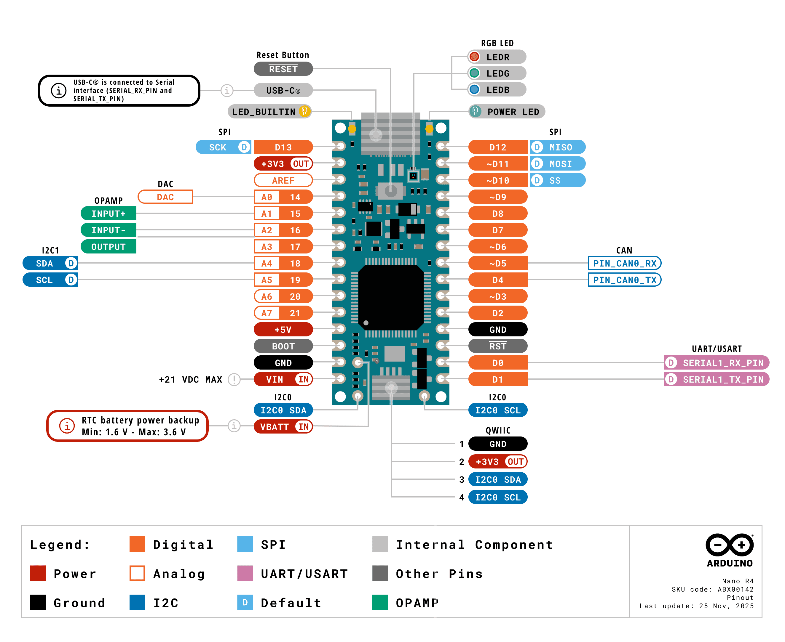
The Nano R4 is based on the original Arduino Nano pin layout. It’s a dual-inline package (DIP) format, meaning it’s got two rows of pins spaced 0.1 inches apart, so it fits nicely on a solderless breadboard. You can get it with or without header pins, and it’s small enough that you can incorporate it in handheld projects as well.
The physical pin numbering for DIP devices goes in a U shape. Holding the micro USB connector at the top, the numbering starts with physical pin 1 on the upper left, counting down the left side to pin 14 on the lower left, then counting from pin 15 on the lower right, to pin 28 on the upper right. For the most part, the left side of the board is power and analog inputs, and the right side is digital I/O pins.
The Nano boards all follow a similar pin layout, as follows, counting from physical pin 1 (upper left) to pin 15 (lower left) across to pin 16 (lower right) to pin 30 (upper right). Figure 1 shows the pin diagram.
Pin 1: Digital I/O 13
Pin 2: 3.3V output
Pin 3: Analog Reference
Pin 4-11: Analog in A0-A7; Digital I/O 14-21 Pin 12: +5V
The full specifications of the Nano R4 and an official pin diagram can be found on its User Manual page.
Typical Breadboard Layout
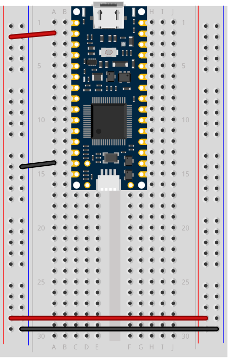
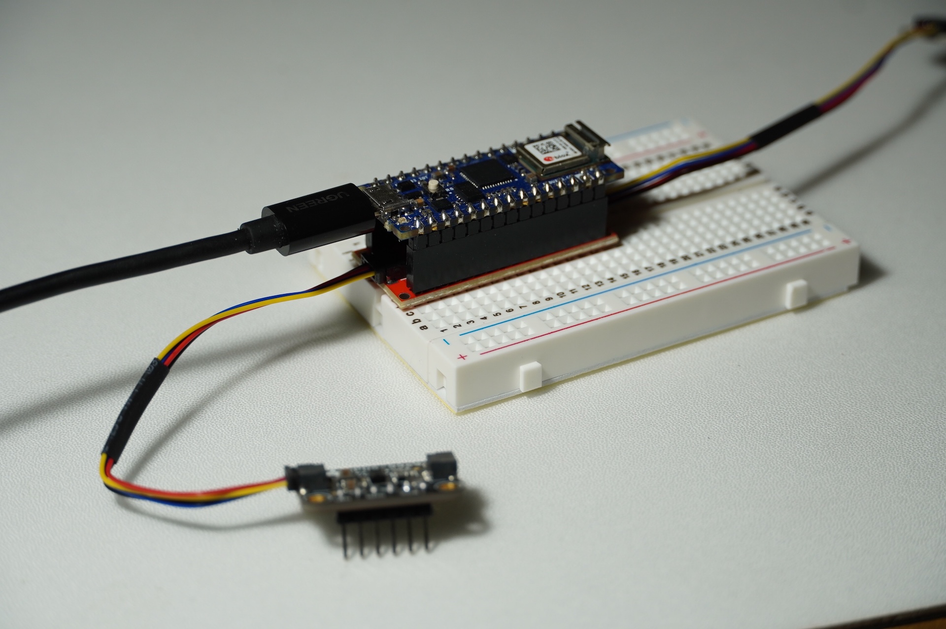
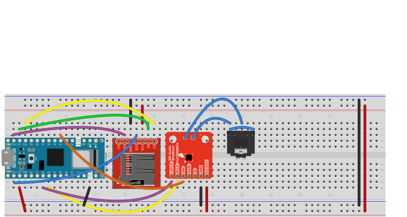
Figure 2. Breadboard view of an Arduino Nano R4 connected to a breadboard.
In a typical breadboard layout for the Nano R4, The +3.3 volts and ground pins of the Nano are connected by red and black wires, respectively, to the left side rows of the breadboard. +3.3 volts is connected to the left outer side row (the voltage bus) and ground is connected to the left inner side row (the ground bus). The side rows on the left are connected to the side rows on the right using red and black wires, respectively, creating a voltage bus and a ground bus on both sides of the board. If you are making a 5-volt circuit instead of a 3.3-volt circuit, you can use the +5 volt pin (pin 12) instead of the +3.3 volt pin.
Like many microcontrollers these days, the Nano R4 uses a USB-C connector. This is a delicate connector, and you shouldn’t handle the board by the connector. If you are mounting the board in a project box or as a wearable and you are using the USB connection, make sure the cable and the board are mounted so that they won’t move relative to each other.
I2C and the Qwiic Connector
The Nano R4 has two I2C buses. The first I2C bus on pins A4 and A5 operates at +5V, like the Nano R4 itself. This bus can be connected to using the Wire library, as usual. The second I2C bus is connected to the qwiic connector, and operates on +3.3V.
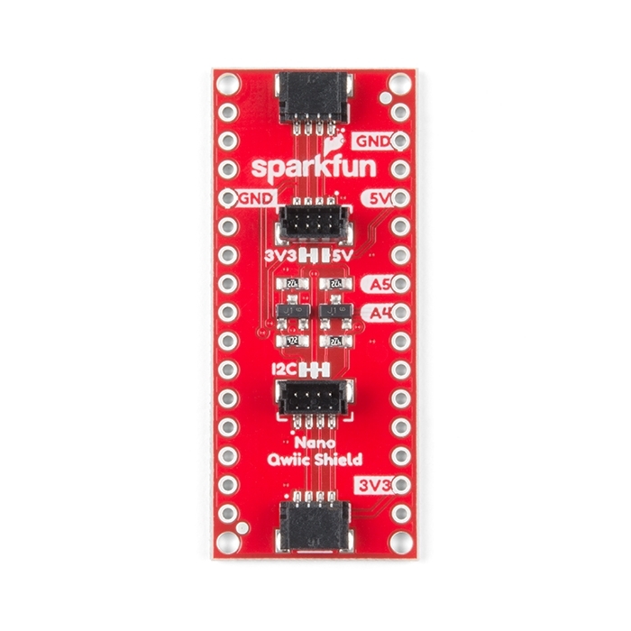
The Qwiic connector, the small rectangular part at the bottom center, gives you an easy way to connect I2C peripherals to your board using Qwiic or Qwiic-compatible connectors. Sparkfun’s Qwiic sensors, Adafruit’s Stemma sensors, and Arduino’s Modulino sensors are all compatible. For more on these, see this section of the I2C introduction. For an example, see this lab on the Sparkfun Qwiic Shield for Nano.
Processor
The Nano 33 IoT has a Renesas R7FA4M1AB3CFM 32-bit processor. It’s considerably faster than the Uno’s processor (48MHz clock speed compared to the Uno’s 16MHz, and a 32-bit processor compared to the Uno’s 8-bit processor) and has more memory (256 kB flash, 32 kB SRAM and 8 kB data memory (EEPROM) compared to the Uno’s 2KB/32KB). That makes for more programming space at a faster speed.
Input and Output (GPIO) Pins
The Nano R4 has 14 digital I/O pins and 8 analog input pins. The analog in pins can also be used for digital in and out, for a total of 22 digital I/O pins. Of those, 6 can be used for PWM out (pseudo-analog out): digital pins 3, 5, 6, 9, 10, and 11. One pin A0, can also be used as a true analog out, because it has a digital-to-analog converter (DAC) attached (here’s an example of how to use it). There are also more hardware interrupt pins than the Uno; pins 0,1,2,3,8,8,12,13, and A1 through A6 can be used as hardware interrupts. Hardware interrupts make it possible to read very fast changes in digital input and output. For example, rotary encoders work best when attached to interrupt pins.
Serial and USB
The Nano 33 IoT is USB-native. That means it can operate as a few different USB devices: asynchronous serial, keyboard or mouse (also known as Human Interface Device, or HID). This is different than the Uno, which has a dedicated USB-to-serial chip on the board, but can only operate as a USB serial device.
There’s also a second asynchronous serial port on pins 0 and 1 that you can use for connecting to other serial devices while still connecting to your personal compuuter. The serial port on pins 0 and 1 is called Serial1, so you’d type Serial1.begin(9600) to initialize it, for example.
Real-Time Clock
The Nano R4 also has a real-time clock module built into the processor, which is accessible using the RTC library that also works on the Uno R4. With this, you can keep track of hours, minutes and seconds much easier. As long as the board is powered, the realtime clock will keep time. Like all libraries, it comes with examples when you install it.
Scheduler
The Nano 33 IoT can run multiple loops at once, using the Scheduler library. When you’ve got an application that needs two or more independent loop functions, this can be a quick way to do it.
Uploading to the Nano R4
If you’ve used an Uno before, and are migrating to the Nano R4 board, you may notice that the serial connection behaves differently. When you reset the MKR, Nano, or Leonardo boards, or upload code to them, the serial port seems to disappear and re-appear. The newer boards can communicate natively using USB, unlike the Uno R3. They don’t need a separate USB-to-serial chip. Because of this, they can be programmed to operate as a mouse, or as a keyboard. Since they are USB-native, their USB connection gets reset when you upload new code or reset the processor. That’s normal behavior for them; it’s as if you turned off the device, then turned it back on. Once it’s reset, it will let your computer’s operating system know that it’s ready for action, and your serial port will reappear. This takes a few seconds. It means you can’t reset the board and then open the serial port in the next second. You have to wait those few seconds until the Arduino board has made itself visible to the computer’s operating system again.
If you’re doing keyboard or mouse, the serial port number will also change when you add those functions. You’ll still be able to send and receive serial data as usual, but you’ll have to re-choose the port in the Boards -> Port submenu after you program your Nano to be a HID device.
If you have trouble getting the Nano R4 to appear in the Arduino IDE, double-tap the reset button at the top center of the board. This will put the board into bootloader mode, meaning that it will show up as a serial device, but not start running the sketch yet. This mode also makes it easier to recover your board if you write a sketch you can’t control, such as a runaway mouse sketch.
In this tutorial, you’ll explore the capabilities of the SparkFun Qwiic Shield for Arduino Nano—a modular shield designed to extend the functionality of the Arduino Nano. This shield enables seamless communication between your microcontroller and various I2c-based peripherals like sensors and some displays. It’s a standard connector type that’s been informally adopted by a few other hardware module manufacturers as well. We’ll cover everything from physical setup and orientation to practical demos using sensors available in the ITP shop.
It’s also worth noting that SparkFun’s Qwiic system is fully compatible with Adafruit’s STEMMA QT ecosystem, which uses the same connector and wiring convention. Beyond SparkFun and Adafruit, other companies such as Pimoroni, Seeed Studio, and Pololu have begun integrating this connector into their I2C sensor and breakout boards as well.
What You’ll Need to Know
Before diving in, you should be comfortable with basic Arduino programming and understand the fundamentals of I2C communication. If you need a refresher, review the I2C Communication Labs for in-depth details.
Things You’ll Need
For this tutorial, gather the following components (see Figures 1–6 for reference images):
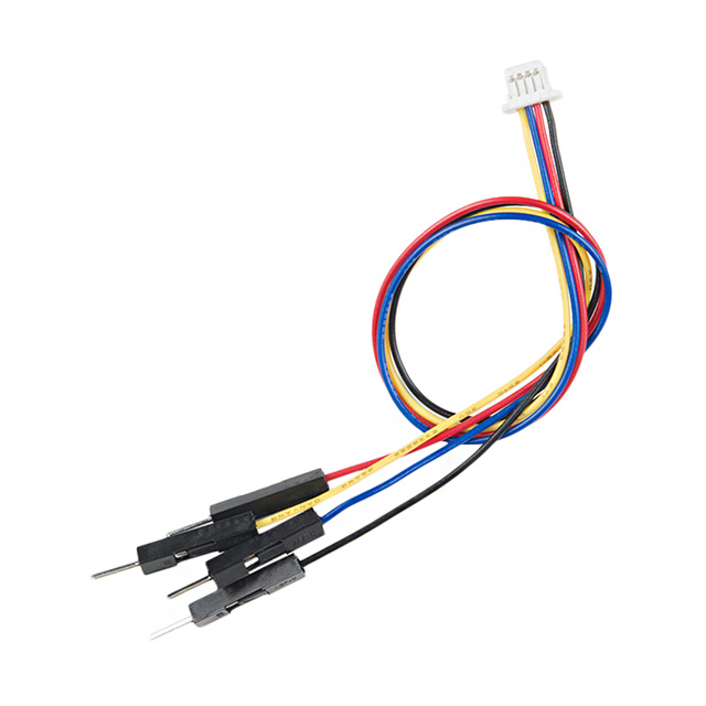
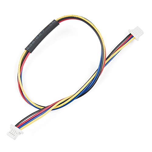
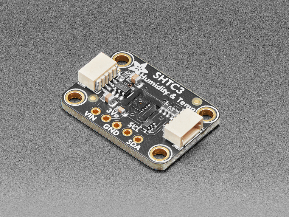
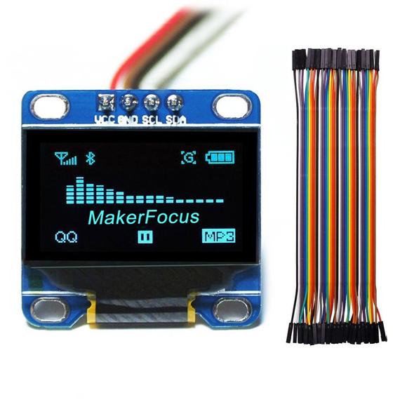
Figure 1. Arduino Nano 33 IoT or other Arduino Nano BoardFigure 2. SparkFun Qwiic Shield for Arduino NanoFigure 3. Qwiic Jumper Adapter CableFigure 4. Qwiic CableFigure 5. SHTC3 Temperature Humidity SensorFigure 6. I2C OLED Display Module 0.96 inches
Shield Orientation and Setup
Physical Orientation
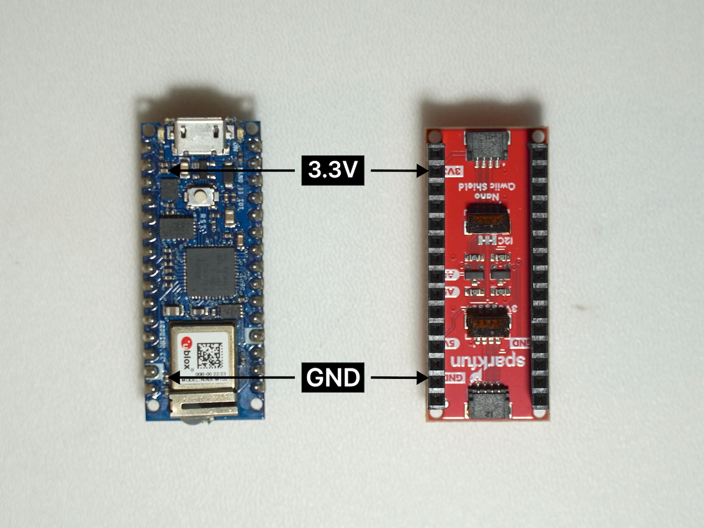
Although the SparkFun Qwiic Shield for Arduino Nano is pinned out exactly like a standard Arduino Nano, it’s still important to verify that you have the correct orientation when mounting the shield. We often reference the 3.3V pin as a quick visual cue to ensure you align everything properly. The shield includes a configurable logic shifting circuit set by the IOREF jumper, which defaults to 3.3V (ideal for boards like the Arduino Nano 33 BLE). If you’re using a 5V Nano variant (such as the Arduino Nano Every), you’ll need to switch the jumper to 5V so that the logic levels match your board’s operating voltage.
Figure 7. Pin alignment guide for powering the SparkFun Qwiic Shield using the Arduino Nano 33 IoT. Ensure that the GND and 3.3V pins are correctly connected to provide stable power and enable Qwiic-based I2C communication.
The Qwiic shield is designed to be mounted below the Nano with which it’s paired. To mount it below would require reversing the standard pin arrangement on the Nano (they are usually on the side of the board without components) and reversing the sockets on the shield.
Figure 8. Arduino on top of the Qwiic shield
Closer Look at the Adapter
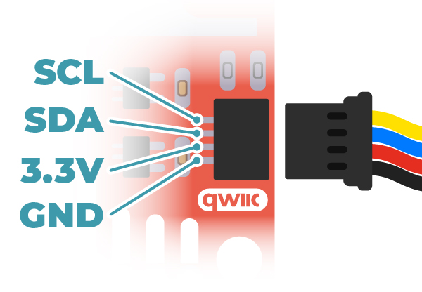
The Qwiic adapter is populated with two 4-pin 1mm JST connectors. These connectors are polarized to prevent incorrect insertion, and the pin order follows the Qwiic standard: GND, 3.3V, SDA, and SCL. When mounting the adapter onto the Nano Qwiic Shield, ensure that the labeled side of the adapter aligns with the corresponding pins on the shield to maintain correct orientation.
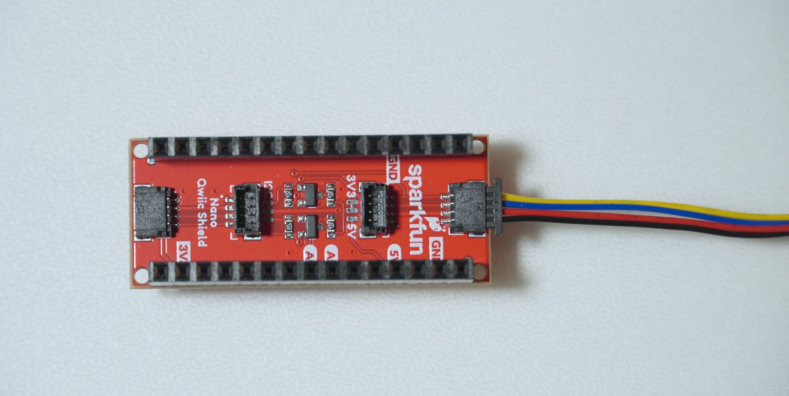
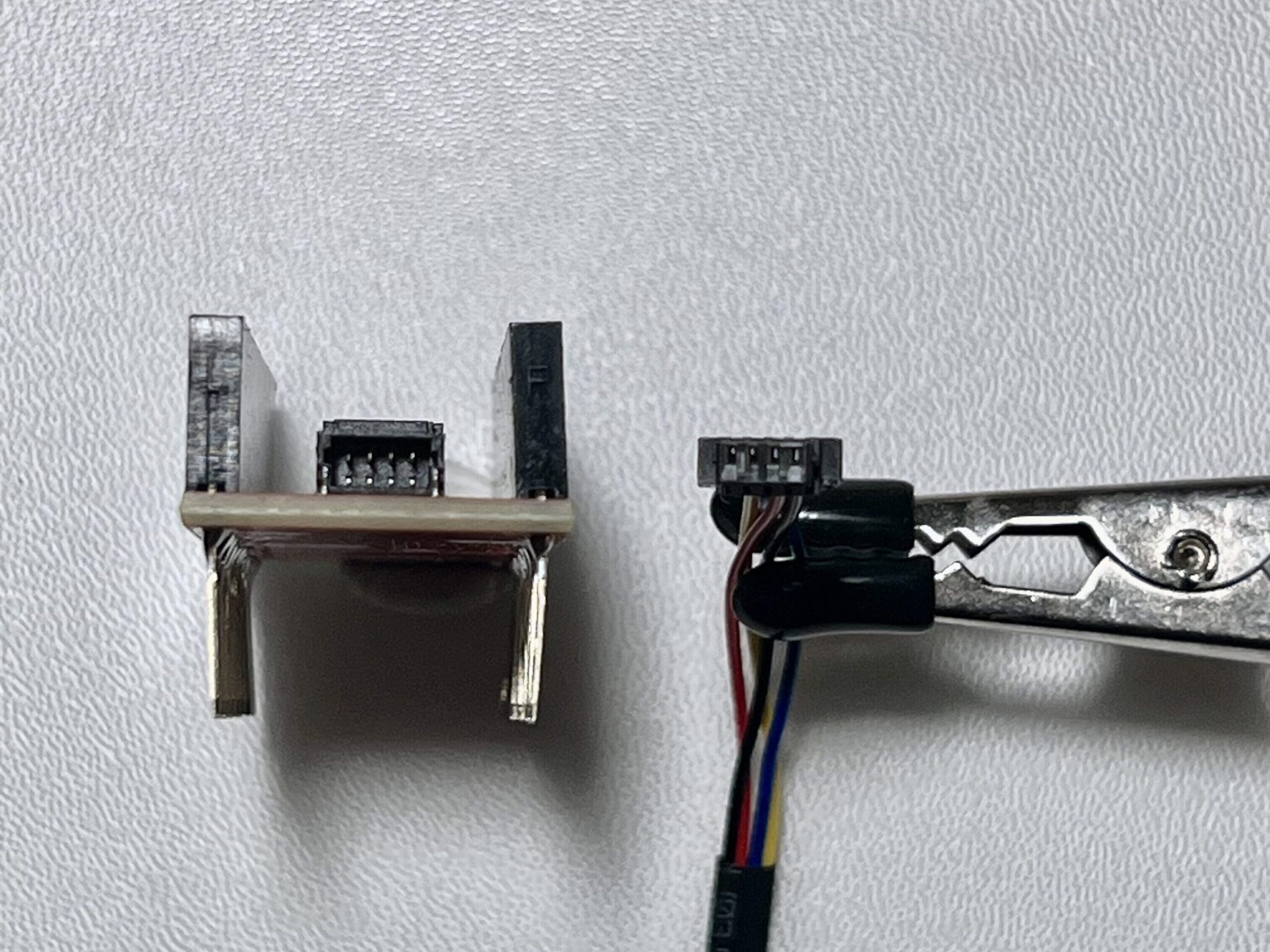
Figure 9. Qwiic connector pinout diagram showing the standard I2C wire order: SCL, SDA, 3.3V, and GND. The polarized JST connector ensures correct orientation, enabling plug-and-play communication between Qwiic-compatible devices without soldering. sourceFigure 10. A SparkFun Nano Qwiic Shield with a Qwiic cable connected, showing the standard I2C wire orientation. Figure 11. Connector alignment for Qwiic interface: the 4-pin JST cable is shown in correct orientation for insertion into the Qwiic Shield’s port
Connection Diagram
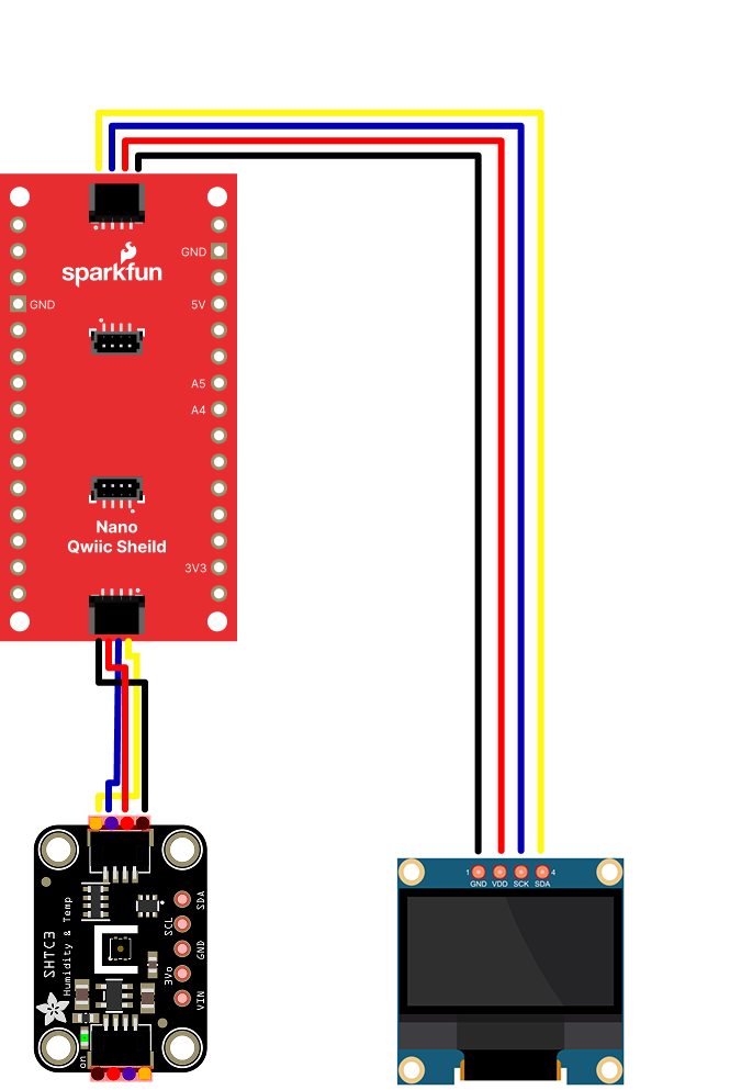
Figure 12 shows the connections between the Qwiic Nano shield and a few typical components.
Figure 12. Wiring diagram for a basic Qwiic I2C setup (Arduino below the shield is not shown in this diagram)
Note that while the Arduino Nano is not shown here, it is connected directly on top of the shield. Note also the placement of I2C communication pins (SDA and SCL). Ensuring the correct physical orientation prevents damage and guarantees reliable operation.
I2C Communication Overview
The SparkFun Qwiic Shield leverages the I2C protocol—a standard for connecting multiple devices with just two wires (SDA and SCL). This tutorial assumes that you’ve reviewed the ITP I2C Communication Labs or Related videos: Intro to Synchronous Serial, I2C for background on the protocol.
I2C Basics
Two-Wire Protocol: Communication occurs over SDA (data) and SCL (clock) lines.
Device Addressing: Each device on the I2C bus is identified by a unique 7-bit address.
Pull-up Resistors: These ensure proper voltage levels on the bus and are often integrated on breakout boards.
Demo Project: Reading Temperature and Humidity on an OLED Display
In this project, we’ll read data from SHTC3 (Humidity and Temp Sensor) and display it on an SSD1306 OLED screen. All components communicate via I2C and connect using Qwiic cables—no breadboards or soldering are required.
⚠️ Note: Many I2C sensors from providers like SparkFun (Qwiic) and Adafruit (STEMMA QT) come in two variants:
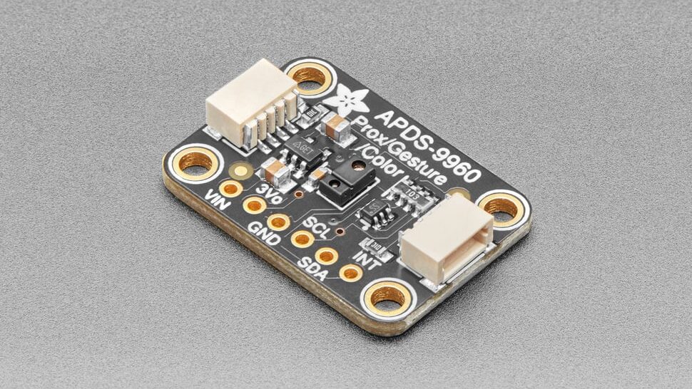
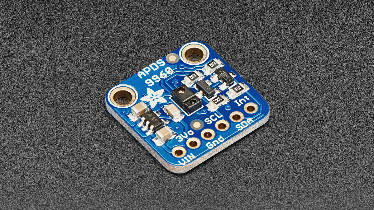
Qwiic/STEMMA QT-compatible versions, which feature JST connectors for plug-and-play wiring (see Figure 13 below) or
Standard breakout boards, which expose I2C pins (SDA, SCL, VCC, GND) but require jumper wires or soldering (see Figure 13 below)
Figure 13. Adafruit APDS9960 Proximity, Light, RGB, and Gesture Sensor – with STEMMA QT / Qwiic connector source
For this demo, we’re using the Qwiic-compatible versions, enabling quick, tool-free connections. However, you can also use standard versions of the same sensors as long as you connect them properly to the corresponding I2C pins.
Hardware Setup
Mount the Shield
Carefully align the Arduino Nano 33 IoT (or other Nano variant) with the SparkFun Qwiic Shield for Arduino Nano.
Ensure the 3.3V pins line up correctly to avoid damaging your board.
Connect the Sensors
Connect sensors to any available Qwiic port using Qwiic cables.
Daisy-chain sensors as needed for project layout.
Attach the OLED Display
If the OLED display includes a Qwiic connector, directly connect it to a free port or daisy-chain.
If not, use a Qwiic Jumper Adapter Cable to connect the necessary pins.
Power and Ground
The Nano’s USB port powers the setup, with the Qwiic Shield distributing 3.3V and GND.
Figure 15. A compact I2C sensor-to-display demo using the Arduino Nano 33 IoT and SparkFun Qwiic Shield.
Install the External Libraries
In the Arduino IDE’s Library Manager (Sketch > Include Library > Manage Libraries…), install the following libraries and dependencies if needed.
In the demo code below, we begin by importing the necessary libraries and defining display parameters such as screen size and I2C address. In the setup() function, we initialize both the SHTC3 sensor and the OLED display, and configure display settings including text size, font, and color. In the loop(), the code reads humidity and temperature data from the sensor every three seconds and updates the OLED screen to show the latest values.
// Libraries for sensor and display communication
#include <SPI.h>
#include <Wire.h>
#include <Adafruit_GFX.h>
#include <Adafruit_SSD1306.h>
#include <Adafruit_SHTC3.h>

// Instantiate sensor object
Adafruit_SHTC3 shtc3 = Adafruit_SHTC3();

// OLED display resolution and initialization
#define SCREEN_WIDTH 128
#define SCREEN_HEIGHT 64
#define OLED_RESET -1 // because the reset pin on the OLED is not being used
#define SCREEN_ADDRESS 0x3C
Adafruit_SSD1306 display(SCREEN_WIDTH, SCREEN_HEIGHT, &Wire, OLED_RESET);

void setup() {
  // initialize serial communication
  Serial.begin(9600);
  // wait 3 seconds if the serial monitor is not open:
  if (!Serial) delay(3000);

  // Initialize SHTC3 sensor, loop indefinitely if this fails:
  if (!shtc3.begin()) {
    Serial.println("Couldn't find SHTC3");
    // stop forever if the sensor is not available:
    while (true);
  }
  Serial.println("Found SHTC3 sensor");

  // Initialize OLED display, halt program if allocation fails
  if (!display.begin(SSD1306_SWITCHCAPVCC, SCREEN_ADDRESS)) {
    Serial.println(F("Couldn't find SSD1306 screen"));
    // stop forever if the display fails:
    while (true);
  }

  // Configure display settings
  display.setTextSize(1);
  display.setTextColor(SSD1306_WHITE);
  display.cp437(true);
}

void loop() {
  // make instances of the sensor elements from the sensor library:
  sensors_event_t humidity, temp;

  // Get fresh data from sensor
  shtc3.getEvent(&humidity, &temp);

  // Clear OLED display and set cursor to start
  display.clearDisplay();
  display.setCursor(0, 0);

  // Display temperature readings
  display.println("Temperature: ");
  display.print(temp.temperature);
  display.println(" °C");
  display.println("");

  // Display humidity readings
  display.println("Humidity: ");
  display.print(humidity.relative_humidity);
  display.println("% rH");

  // Update display with new data
  display.display();

  // Wait for 3 seconds before refreshing
  delay(3000);
}
Final Result
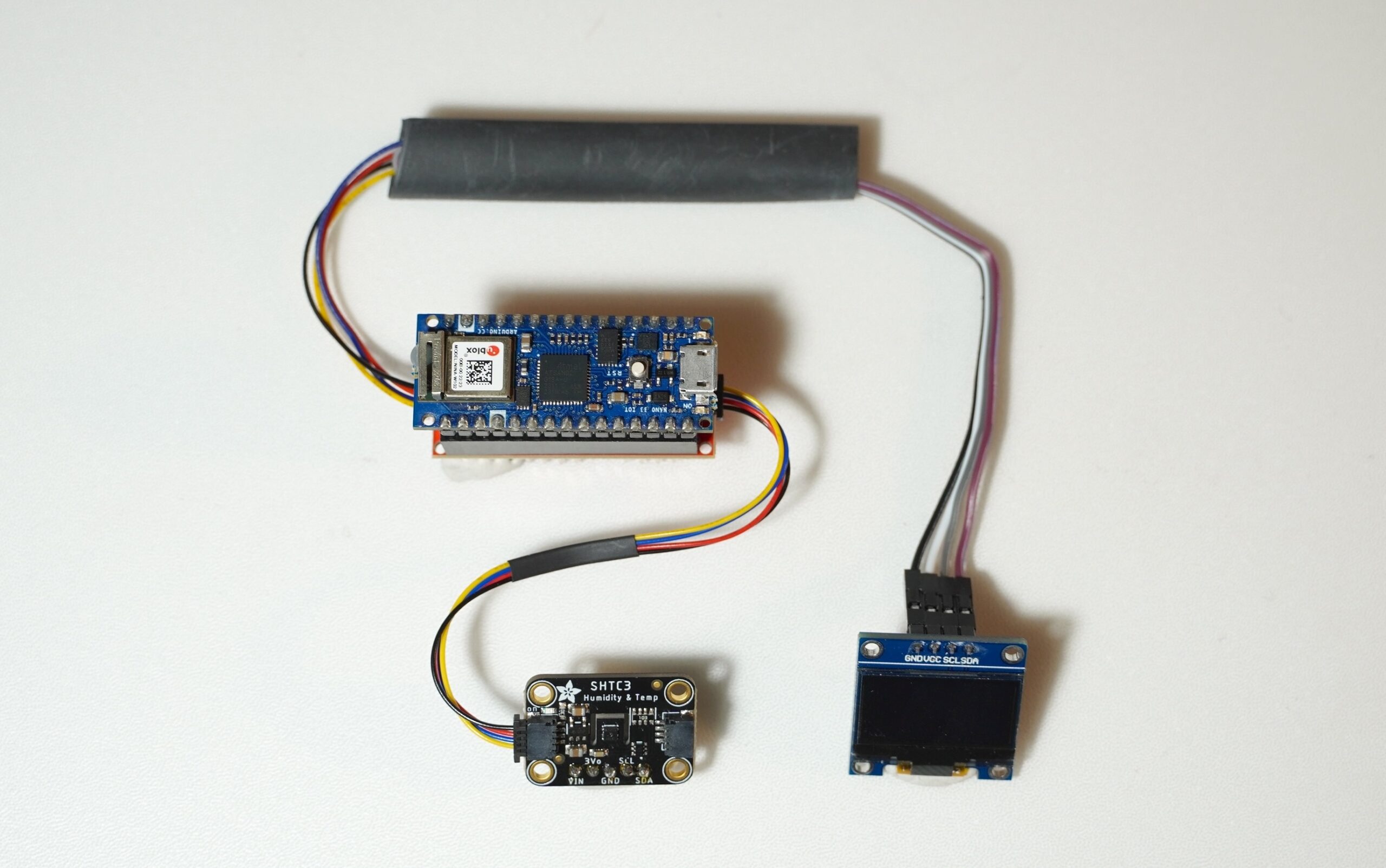
Figure 16. Real-time environmental monitoring demo using an Arduino Nano with SparkFun’s Qwiic Shield. The SHTC3 sensor measures temperature and humidity, displaying live data on the SSD1306 OLED screen
Further Use Cases
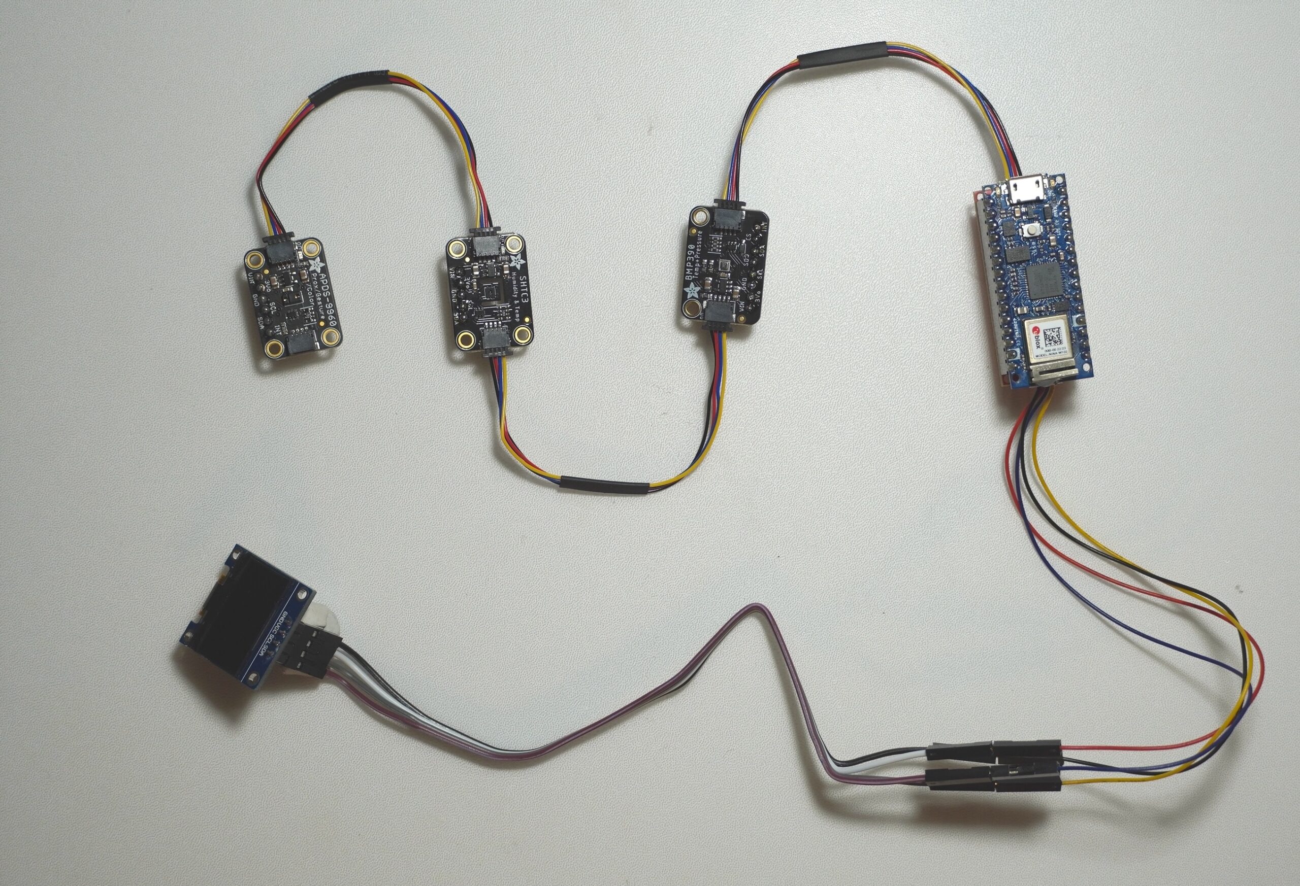
For a more advanced setup, we can expand the I2C chain by adding more sensors or devices. In the demo below, there is an APDS-9960 gesture sensor and a BMP388 pressure sensor alongside the SHTC3 temperature and humidity sensor. The user can change the data display on the screen by simple hand movement. You can find examples for these sensors at this link.
Figure 17. Chain of I2C sensors and display connected to an Arduino Nano 33 IoT using SparkFun’s Qwiic system.Figure 18. Live sensor data in action—temperature and humidity readings from an SHTC3 sensor are displayed on an OLED screen, while an APDS-9960 gesture and proximity sensor is also daisy-chained via Qwiic. This setup demonstrates how multiple I2C devices can work together seamlessly over a single bus.
Conclusion
The Sparkfun Qwiic Shield can simplify sensor integration and communication with Arduino Nano variants. It’s not the only way to connect IC components, but if you are, and if you’re using a Nano, it’s a handy tool. Whether you’re building a simple temperature monitor or a more complex interactive installation, understanding the practicalities of shield orientation, I2C communication, and connection strategies is key.
In the stepper motor and H-bridge lab, you learned how to control a stepper motor with a dual H-bridge driver, specifically the TB6612FNG. This is not the only driver for controlling a stepper. Step & direction stepper drivers offer a simpler approach, from the microcontroller side. They have just two control pins, one for step and one for direction. They also feature configuration pins that let you set the step pin to move the motor a full step, a half step, or less. This is called microstepping, and you can find stepper drivers that will work as low as 1/256th of a step. This allows finer control over the stepper motor. In this lab you’ll learn how to use a step & direction controller to control a stepper motor.
What You’ll Need to Know
To get the most out of this lab, you should be familiar with the following concepts. You can check how to do so in the links below:
A solderless breadboard with two rows of holes along each side.
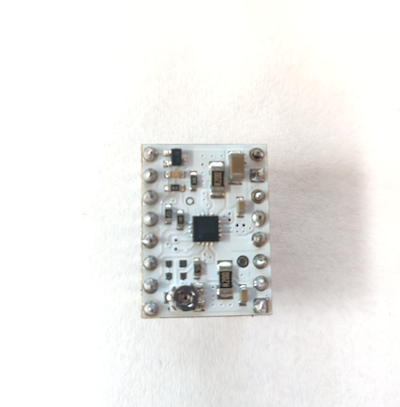
Stepper motor driver model STSPIN220
Flexible jumper wires.
a stepper motor
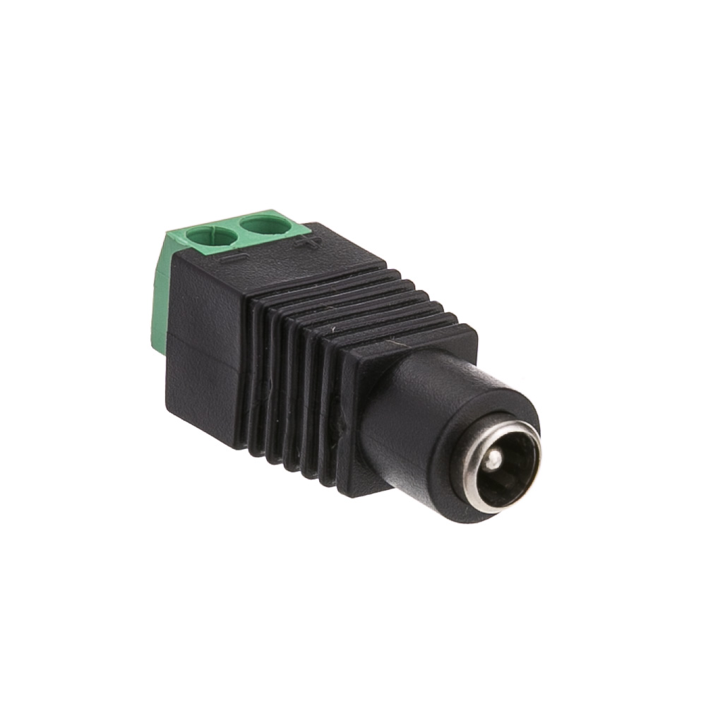
A DC Power Jack
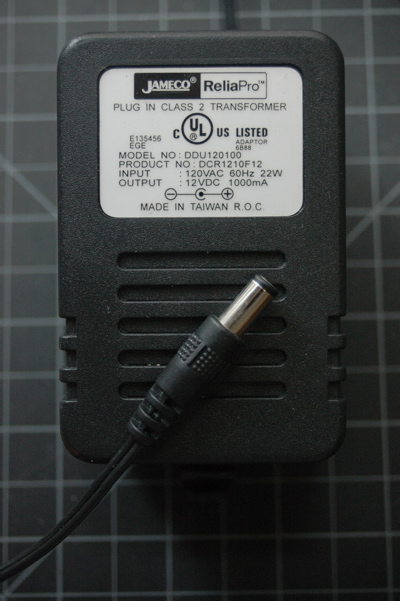
DC Power Supply
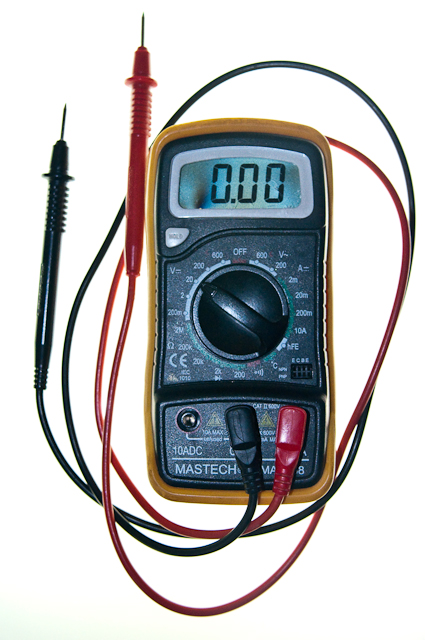
Multimeter. You’ll need this to check the coils and set the motor driver’s current limit.
Figures 1-8. The parts you’ll need for this exercise.
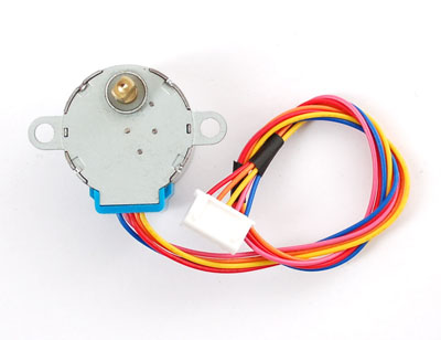
The motor shown in the images here is a 5V Small Reduction Stepper Motor, 32-Step, with 1:16 Gearing. This motor is a useful starter motor for steppers because it can run on the current and voltage supplied by your Arduino without an external power supply. The driver is a STMicro STSPIN220 on a Pololu breakout board. There are a number of other step & direction motor drivers available if the STSPIN220 doesn’t meet your needs. Control for all of them will be similar to what you see below. In fact, Pololu makes a number of carrier boards for different step & direction drivers, all with the same pin layout. The principles in this lab, and the library used, will work with other stepper motors and step & direction drivers as well, though you will have to make some modifications depending in which parts you are using.
Good Safety Practice
When you’re working with motors, you’re often dealing with high voltage, high current, or both. You should be extra careful never to make changes to your circuit while it is powered. If you need to make changes, unplug the power, make your changes, inspect your changes to be sure they are right, and then reconnect power.
It’s also a good idea to disconnect your motor from your circuit before uploading new code to your microcontroller. Often the current draw of the motor will cause the microcontroller to reset, and cause uploading problems. To avoid this, disconnect your motor before uploading, and reconnect it after uploading.
Because motors consume a lot of current when they start up, it’s common to add a decoupling capacitor of 10-100 µF near the voltage input to your driver and/or microcontroller. You’ll see this in the figures below. It will smooth out any voltage changes that occur as a result of the motor’s changing current consumption.
Prepare the breadboard
Connect power and ground on the breadboard to power and ground from the microcontroller. On the Arduino module, use the 5V or 3.3V (depending on your model) and any of the ground connections, as shown in Figures 9 and 10.
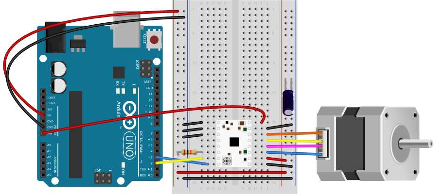
Figure 9. Breadboard drawing of an Arduino Uno on the left connected to a solderless breadboard on the right
Figure 9 shows an Arduino Uno on the left connected to a solderless breadboard, right. The Uno’s 5V output hole is connected to the red column of holes on the far left side of the breadboard. The Uno’s ground hole is connected to the blue column on the left of the board. The red and blue columns on the left of the breadboard are connected to the red and blue columns on the right side of the breadboard with red and black wires, respectively. These columns on the side of a breadboard are commonly called the buses. The red line is the voltage bus, and the black or blue line is the ground bus.
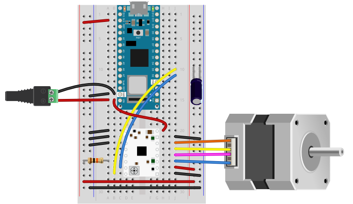
Figure 10. Breadboard view of an Arduino Nano mounted on a solderless breadboard.
As shown in Figure 10, the Nano is mounted at the top of the breadboard, straddling the center divide, with its USB connector facing up. The top pins of the Nano are in row 1 of the breadboard.
The Nano, like all Dual-Inline Package (DIP) modules, has its physical pins numbered in a U shape, from top left to bottom left, to bottom right to top right. The Nano’s 3.3V pin (physical pin 2) is connected to the left side red column of the breadboard. The Nano’s GND pin (physical pin 14) is connected to the left side black column. These columns on the side of a breadboard are commonly called the buses. The red line is the voltage bus, and the black or blue line is the ground bus. The blue columns (ground buses) are connected together at the bottom of the breadboard with a black wire. The red columns (voltage buses) are connected together at the bottom of the breadboard with a red wire.
How the Stepper Motor Works
A stepper motor is basically two motor coils in one motor, which allows you to turn the motor in steps. For more on this, see this stepper motor page.
The motor shown in this lab, a 5V Small Reduction Stepper Motor, 32-Step, with 1:16 Gearing, is typical of a class of stepper motors you can find using the designation 28BYJ-48. They come in a few varieties. There are 5V and 12V models, and there are versions like the one shown here, that have a gearbox on the top to increase their torque and increase the number of steps per revolution. The un-geared models have as few as 32 steps per revolution. This model has 32 steps per revolution and a 1/16 reduction gear box, giving it 32 * 16, or 512 steps per revolution. You can find models with an even higher reduction as well.
A stepper motor like this one has two coils to control it as shown in Figure 11. Each coil has a center connection as well, and the center connections are joined together, which is what makes this a unipolar stepper. If you don’t connect the center connection, then the motor will work like a bipolar stepper, each coil operating independently. This is how you’ll use it for this exercise. Each coil will connect to one control channel of the motor driver. The pink and orange wires are connected to the first coil. They will connect to one channel of the motor driver, while the yellow and blue wires are the other coil, and will connect to the other channel of the bridge (channel B). In this case, the red wire, pin 1, will not be used.
Figure 11. Schematic drawing of a stepper motor.
A bipolar stepper motor typically omit the red wire and just have two independent coils. A bipolar model like this 3.9V NEMA-8 stepper from Pololu would also work with this lab.
Check the Motor Coils’ Resistance
The wiring pattern in Figure 11 is typical, for the 28BYJ-48 motors. Nonetheless, it’s a good idea to check the wiring by measuring the coil resistance. The motor shown here has a coil resistance (impedance) of about 42 ohms. For a bipolar motor, each pair of coils (e.g. blue and yellow, orange and pink) would give you the motor’s rated coil resistance. Since this is a unipolar motor, you should read approximately 22-24 ohms across red and each of the other wires, and about 42-45 ohms across each pair (blue-yellow and orange-pink).
The sequence of the wires on the motor’s connector may vary from one manufacturer to another, so it’s a good idea to measure the resistance, then write down the pin order for reference later on.
How The Motor Driver Works
The STSPIN220 can handle a motor supply voltage from 1.8 to 10V, and it operates on a logic voltage of 3.3–5V. It can control an output current of 1.1A per coil.
The motor driver has the following pins. The pin numbers shown here are for the Pololu breakout board. The pins are numbered here in a DIP fashion, in a U-shape from top left to bottom left, then bottom right to top right. The list below describes the pins in numeric order.
Enable – enables the driver when you take it LOW and disables it when you take it HIGH. The breakout board pulls this pin LOW by default, so if you don’t connect it, your motor should work fine.
Mode 1 -Configuration pin for microstepping
Mode 2 – Configuration pin for microstepping
1 – not connected by default
2 – not connected by default
Standby – Puts the the driver in a low-power standby mode and disables the motor when you take it LOW.
Step/Mode 3 -When you pulse this pin HIGH then LOW, the motor moves forward one step. Also functions as a configuration pin for microstepping.
Dir/Mode 4 – When you pulse this pin HIGH, the motor in one direction when you pulse the step pin. When you take it LOW, it moves in the other. Also functions as a configuration pin for microstepping.
Ground – ground
Vcc – Logic voltage. Connect this to the Vcc of your microcontroller, for example 5V for an Uno or 3.3V for a Nano 33 IoT
A1 – Motor output coil 1
A2 – Motor output coil 1
B2 – Motor output coil 2
B1 – Motor output coil 2
Ground – ground
VMOT – motor voltage supply input, 1.8-10V.
Connect the Motor Driver and Set the Current Limit
Many step and direction drivers like the STSPIN220 have an adjustable current limit built into the driver. This lets you set the maximum output current to match the current your motor needs. Pololu has a video explaining this process. This is important, because if you don’t set the current limit correctly, you risk damaging the driver and the motor. The details follow here. You have to know your motor’s desired current, then you use a formula to work out the value of a current limiting resistor for the driver.
If you have the motor’s current from the datasheet (110mA for the motor listed above), then you’re all set. If you don’t, you can calculate it from the motor’s voltage and the resistance of its coils. First, measure the resistance of one coil, as explained in the stepper motor lesson. Remember that current, voltage, and resistance are all related using the formula
Voltage = Current * Resistance
For example, if your motor’s coil resistance reads 45.4 ohms, and it runs on 5 volts, then the current = 5 / 45.4, or about 110 mA.
To prepare for this, connect the STSPIN220 board as shown in Figures 12 and 13. Do not connect a motor yet. You’re powering the board up just so you can set the current limit.
The board is mounted straddling the center row of a breadboard, and the following pins on the STSPIN220 are connected:
Pin 1, Enable – connected to the ground bus on the left side of the breadboard
Pin 9, Ground – connected to the ground bus on the right side of the breadboard
Pin 10, Vcc – Logic voltage. Connected to the voltage bus on the right side of the breadboard
Pin 15, Ground – connected to the ground bus on the right side of the breadboard
Pin 16, VMOT – Connected to the voltage bus on the right side of the breadboard. If you were using an external power supply for a higher voltage stepper motor, you would connect this to the positive terminal of the external supply.
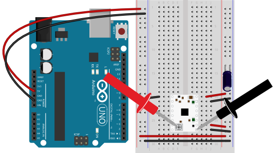
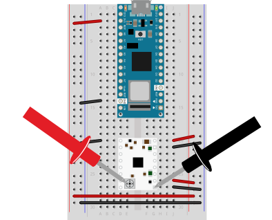
Figure 12. Breadboard view of an SDSPIN220 stepper motor driver on a breadboard, powered by 5V from an Arduino Uno. Multimeter leads are touching the trimmer pot of the STSPIN220 and the ground pin, to read the current limiting voltage. Figure 13. Breadboard view of an SDSPIN220 stepper motor driver on a breadboard, powered by 3.3V from an Arduino Nano 33 IoT. Multimeter leads are touching the trimmer pot of the STSPIN220 and the ground pin, to read the current limiting voltage.
Pololu makes its step & direction driver boards with a built-in trimmer potentiometer to act as a current limiting resistor. It’s usually at the bottom of the board. Calculating the value of this resistor is explained in detail in section 6 of the STSPIN220 data sheet. Pololu have summarized it in a formula below.
To set the current limit, you power up the driver without a motor attached and measure the voltage between this trimmer pot and ground. Then you turn the trimmer pot until you read the reference voltage for the current limit, or VREF. In Figures 12 and 13 there are multimeter probes shown, used to measure voltage. The red probe (positive) is touching the trimmer pot on the STSPIN220 and the black probe (negative) is touching pin 9, the ground pin. Set your multimeter to read voltage in the range of your Vcc (3.3 to 5V), then touch the leads to the trimmer pot and to ground as shown in figures 12 and 13. You should get a voltage between zero and Vcc. Then turn the pot with a small screwdriver until you read your desired VREF.
For the STSPIN220, the current limit formula is as follows:
Current= VRef * 5
Rearranging that to get the voltage on the trimmer pot:
VRef = Current / 5
So, if your desired current is 110 mA, or 0.11 A, then VREF = 0.11 / 5, or 0.022V. Turn your pot until the voltage reads that value (or whatever you calculated it to be for your motor) and you’re ready to go. The trimmer pot is small and difficult to turn, so try to get in the general range of your VREF. You probably won’t get it exactly. If you find the motor or the driver is excessively hot while running (if you can’t touch it comfortably) then you should re-adjust the trimmer pot to get closer to your proper VREF.
You can now disconnect from your power supply, add the motor, and reconnect to program the microcontroller.
Connect the Motor
This motor nominally runs on 5 volts. It will run as low as 3.3 volts if you give it enough current (about 110 mA). It can run on the current supplied to an Uno or Nano 33 IoT’s USB connection. Ideally, though, you should run it from an external power supply, as described later in the lab.
To finish your stepper motor circuit, connect the motor according to Figures 14 through 16.
Table 1 below describes the pin connections for the circuit. The STSPIN220 is still connected to the breadboard as shown previously in figures 12 and 13, but now the motor’s coils are connected to pins 11 – 14 of the motor driver and the driver’s step and direction pins (pins 7 and 8 respectively) are connected to digital output pins 2 and 3 of the Arduino, respectively. The two mode pins (pins 2 and 3) are connected to ground, and the standby pin (pin 6) is connected to Vcc through a 10-kilohm resistor.
Motor Driver Physical pin number
Pin function
Circuit Connection
1
Enable
Ground
2
Mode 1
Ground
3
Mode 2
Ground
4
1
not connected
5
2
not connected
6
Standby
10-kilohm resistor to Vcc
7
Step
Arduino digital pin 2
8
Direction
Arduino digital pin 3
9
Ground
Ground
10
Vcc
Arduino Vcc (3.3 or 5V)
11
A1
Motor coil 1
12
A2
Motor coil 1
13
B2
Motor coil 2
14
B1
Motor coil 2
15
Ground
Ground
16
VMOT
Arduino Vcc if using USB power. Arduino Vin if using an external power supply.
Table 1. STSPIN220 connections to Arduino circuit
Figure 14. Schematic diagram of an STSPIN220 stepper motor driver and stepper motor connected to an Arduino.
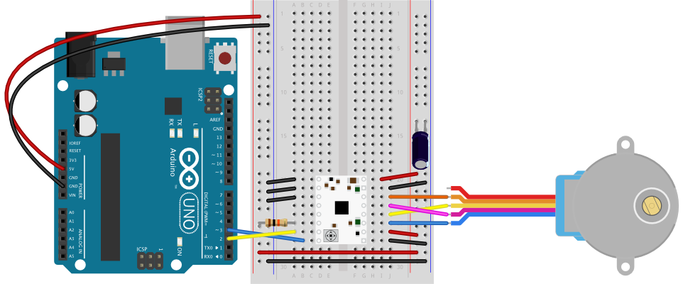
Figure 15. Breadboard diagram of an STSPIN220 stepper motor driver and stepper motor connected to an Arduino Uno.
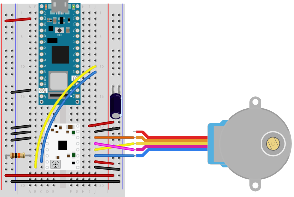
Figure 16. Breadboard diagram of an STSPIN220 stepper motor driver and stepper motor connected to an Arduino Nano 33 IoT.
Once you have the motor and the driver connected, you’re ready to program the microcontroller.
Program the microcontroller
You don’t need a library for a step and direction controller, though there are several out there, to do things like ramp the speed up and down, ease in and out, and so forth. All you need to do to move the motor is to set the direction pin, and to pulse the motor high then return to low. A 3-millisecond pulse will do the job reliably. If you need more speed, you can try reducing this down to 2 or even 1ms, once you know the motor’s working properly.
Regardless of what motor driver you are using, the first thing you should do after wiring up a stepper motor is to write two test programs, one to test if it’s stepping, and one to test if it can rotate one revolution in both directions.
For your first program, it’s a good idea to run the stepper one step at a time, to see that all the wires are connected correctly. If they are, the stepper will step one step forward at a time, every half second, using the code below.
const int stepPin = 2;
const int dirPin = 3;

void setup() {
  pinMode(stepPin, OUTPUT);
  pinMode(dirPin, OUTPUT);
}

void loop() {
  // motor  direction:
  digitalWrite(dirPin, HIGH);
  // step the motor one step:
  digitalWrite(stepPin, HIGH);
  delay(3);
  digitalWrite(stepPin, LOW);
  // wait half a second:
  delay(500);
}
Once you’ve got that working, try making the stepper move one whole revolution at a time using the code below:
const int stepPin = 2;
const int dirPin = 3;
const int stepsPerRevolution = 512;
bool direction = HIGH;

void setup() {
  pinMode(stepPin, OUTPUT);
  pinMode(dirPin, OUTPUT);
}

void loop() {
  // motor  direction:
  digitalWrite(dirPin, direction);
  // move one revolution :
  for (int step = 0; step < stepsPerRevolution; step++) {
    // step the motor one step:
    digitalWrite(stepPin, HIGH);
    delay(3);
    digitalWrite(stepPin, LOW);
    delay(1);
  }
  // wait half a second:
  delay(500);
  // change direction:
    direction = !direction;
}
When you run this code, you should see the motor turn one revolution, wait half a second, then turn one revolution in the other direction.
My motor’s only going one direction!
If you find that the motor only turns in one direction, you probably have the pin connections wrong. It could be that you got the order wrong. Try rearranging the order of the pins. Disconnect power each time you try changing your connections. First, try swapping the two pins on each coil (e.g. blue and yellow, pink and orange) and run it again. If that fails, swap one wire from one coil for one wire from the other coil. Keep trying variations until your motor goes around in one direction, then goes around in the opposite direction.
Unipolar Stepper Control
The steps above showed you how to control your motor as a bipolar stepper, but the motor shown is actually a unipolar motor. Remember the red wire you didn’t connect? That wire connects the two coils and can act as a common power source or ground wire. To use the motor as a unipolar motor, try connecting that wire (wire 1) of the motor to the Vin power supply from the DC power jack. You should see that there’s not a lot of difference.
Attach Something to the Stepper
If you want to mount an arm or pointer to the stepper motor, you need to make a hole for the pointer that fits the shaft perfectly. You could measure this with a caliper. There are also collars and shaft couplers that you can buy for various stepper motors that will allow you to attach things to your stepper. ServoCity has a number of examples, as does Pololu. To pick a good shaft adapter, you need to know what you’re going to do with the stepper, and what the size and shape of the shaft is.
Using an External Power Supply
Although the example shown above used a motor that can run on the voltage and current supplied to the Arduino via USB, this is not the norm for stepper motors. Most of the time you need to use an external power supply. You should match your supply to your motor. Keep in mind that if you have, say, a 12-Volt power supply and a 5-volt motor, you can add a 5-volt voltage regulator, as shown in the breadboard lab. Figures 17 through 19 show a few different options for powering different stepper motors.
Figures 17 and 18 show how you might power a 9V stepper motor from an Uno or Nano, respectively. Figures 17 and 18 show a NEMA-17 stepper motor. Figure 19 shows how you could power a 5V stepper from a Nano, using a 9-12V DC power supply for the Nano and a 5V voltage regulator for the motor and motor driver.
The STSPIN220 can run motors from 1.8-10V. If you need to run a motor at a voltage greater than 10V, there are several other step and direction motor drivers that can do the job. For example, the A4988 is similar to the STSPI220, but has a motor voltage range of 8-35V. Many of them come with the same or similar pin arrangements as well. For a comparison, see the Step & Direction Drivers compared table in the Controlling Stepper Motors page of this site.
It’s worth noting that when the Nano 33 IoT is powered from its Vin pin, the USB connection no longer powers the Nano. Instead, the Vin powers the Nano. You can still get 3.3V from the 3.3V out pin (pin 2), however.
The exact voltage and amperage requirements for a stepper motor circuit will depend on the motor you are using. These images show a few options that can work, but you should adapt them depending on the particular electrical characteristics of your motor.
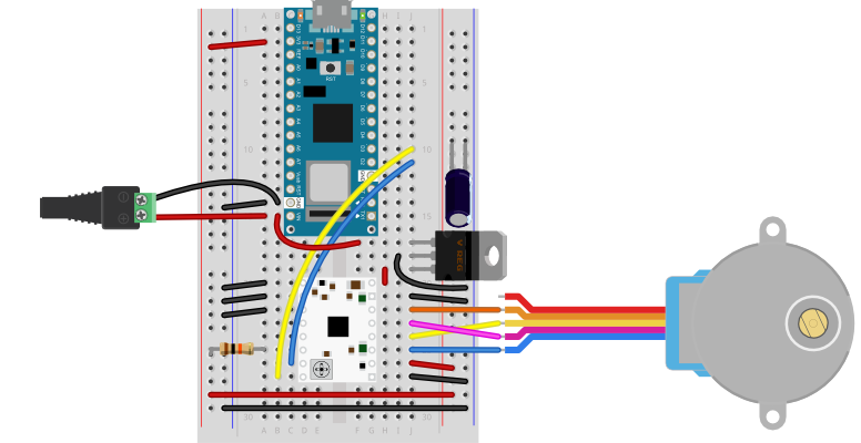
Figure 17. Breadboard view of an STSPIN220 running a 9V NEMA-style stepper motor from an Arduino Uno. The circuit is similar to Figure 15 above, but in this image the STSPIN220’s VMOT pin (pin 16) is connected to the Uno’s Vin pin. The whole circuit would be powered by a 9V DC power supply connected to the Uno’s power jack. Figure 18. Breadboard view of an STSPIN220 running a 9V NEMA-style stepper motor from an Arduino Nano 33 IoT. The circuit is similar to Figure 16 above, but in this image an external power jack is connected to the Nano’s Vin pin (pin 15) and grounded to its ground pin (pin 14). The STSPIN220’s VMOT pin (pin 16) is connected to the Nano 33 IoT’s Vin pin (pin 15) and the positive terminal of the power jack. The Nano would then need to be powered by a 9V DC power supply connected to the power jack. Figure 19. Breadboard view of an STSPIN220 running a 5V stepper motor from an Arduino Nano 33 IoT with an external voltage regulator. The circuit is similar to Figures 16 and 18 above, but in this image an external power jack is connected to the Nano’s Vin pin (pin 15) and grounded to its ground pin (pin 14). A 7805 5V voltage regulator has been added to the breadboard in three rows just above the STSPIN220 on the right side of the breadboard. The regulator’s input pin is closest to the top of the board, and is connected to the Nano’s Vin pin and the positive terminal of the power jack. Its ground is in the middle, and is connected to the right side ground bus of the breadboard. Its output is closest to the bottom and is connected to the STSPIN220’s VMOT pin (pin 16). The whole circuit could be powered by a 9-12V DC power supply connected to the power jack. The regulator would ensure that the motor and the STSPI220 always get 5V and up to 1A.
Advanced Features: Speed Control, Microstepping, and G-code
This lab has covered the basics of step & direction drivers. These drivers are capable of much more control, depending on how you wire them and how you program the microcontroller to control them.
Controlling the speed of a motor is managed by changing the timing between steps. You can manage this in your own code by changing the delay after each step pulse, or you can use a library like accelStepper which has options for speed control.
Microstepping allows you to control a stepper in 1/2, 1/4, 1/8, or as low as 1/256 step increments. The number of microsteps depends on the driver you are using. You set the microstep increment using the mode pins. Pololu’s documentation for the STSPIN220 covers the details of this for this board (see the section titled Step (and microstep) Size). Other step & direction boards will have similar instructions.
Step and direction motor controllers are often used in DNC machines like 3D printers and 3D mills. These machines have a communication format called G-code which describes how the machine should move to print or carve a shape. The GRBL library for Arduino translates G-code into a series of stepper motor movements. There are many sites which explain this in more depth, like the one at this link.
Applications
Stepper motors have lots of applications. One of the most common is to make a tw0- or three-axis gantry for CNC plotters, printers, and mills. A gantry is a structure on which you mount motors and the equipment that they are moving in order to achieve a task. Evil Mad Science’s AxiDraw is a good two-axis example. You can also use steppers to create animation in art projects, as seen in Nuntinee Tansrisakul’s Shadow through Time. Heidi Neilson’s Moon Arrow is another example that uses stepper motors and geolocation tools to make an arrow that always points at the moon.
In the Introduction to Asynchronous Serial Communication lab, you learned about various methods for managing the communications between computers via asynchronous serial communication. These included formatting your data as ASCII-encoded strings or raw serial bytes and managing the flow of data using handshaking. In the P5.js WebSerial Input Lab, you sent data from one sensor to a personal computer. In this lab, you’ll send data from multiple sensors to a program in p5.js. using the p5.WebSerial library. You’ll use the data from the sensors to create a pointing-and-selecting device (i.e. a mouse).
Figures 1-5 below are the parts you’ll need for this exercise. Click on any image for a larger view.
Figure 1. Microcontroller. Shown here is an Arduino Nano 33 IoT
Figure 2. Jumper wires. You can also use pre-cut solid-core jumper wires.
Figure 3. A solderless breadboard
Figure 4. A pushbutton
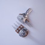
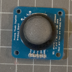
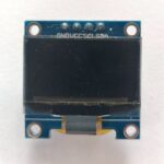
Figure 5. two potentiometers. You can use any two analog sensors in place of these if you prefer.
Connect the Sensors
For this exercise, you’re going to need two analog inputs to your microcontroller, and one digital input. It doesn’t matter what they are, so use something that’s easy for you to set up. The photos and schematic in this lab show potentiometers and a pushbutton. You don’t have to use these, though. Any three sensor inputs will do the job. If you’re looking for options, consider:
Figure 6. A joystick, which consists of two potentiometers and a pushbutton
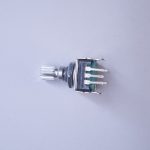
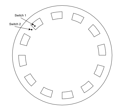
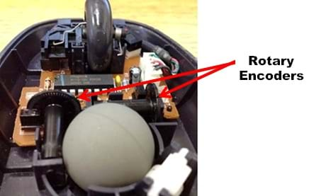
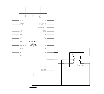
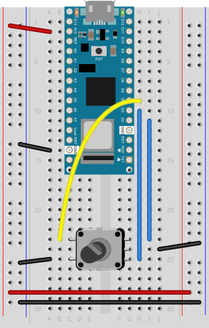
Figure 7. Rotary encoders, which include a built-in pushbutton
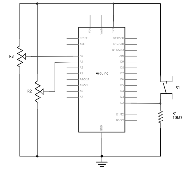
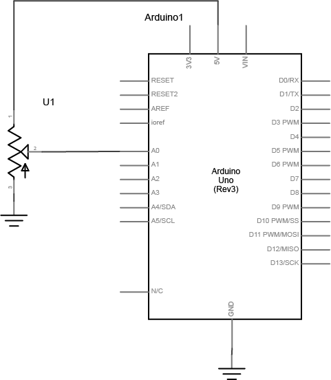
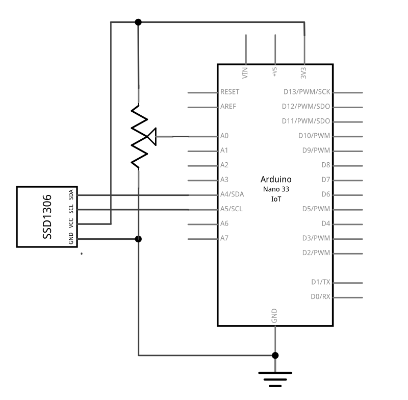
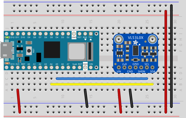
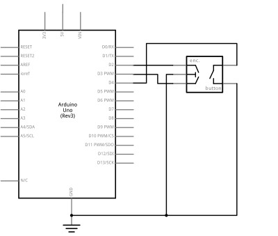
Figure 9. Schematic view of an Arduino attached to two potentiometers and a pushbutton. The potentiometers’ center pins are connected to the Arduino’s A0 and A1 inputs, respectively. Their left pins are connected to the voltage bus, and the right pins are connected to the ground bus, respectively. The pushbutton is connected from the Arduino’s voltage output to pin D2. a 10-kilohm connects the junction of the switch and pin D2 to ground.
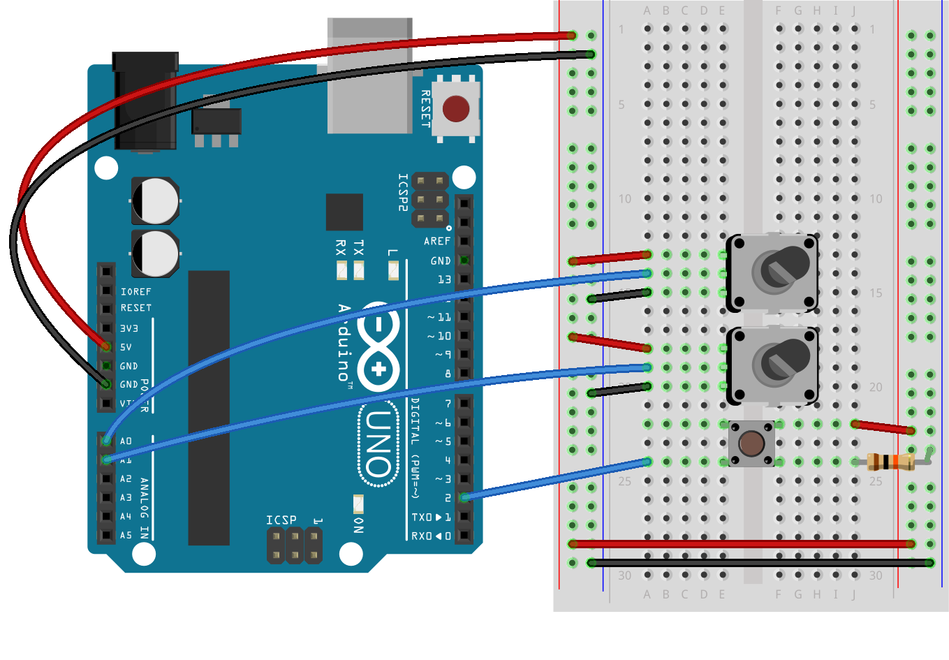
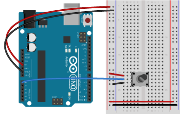
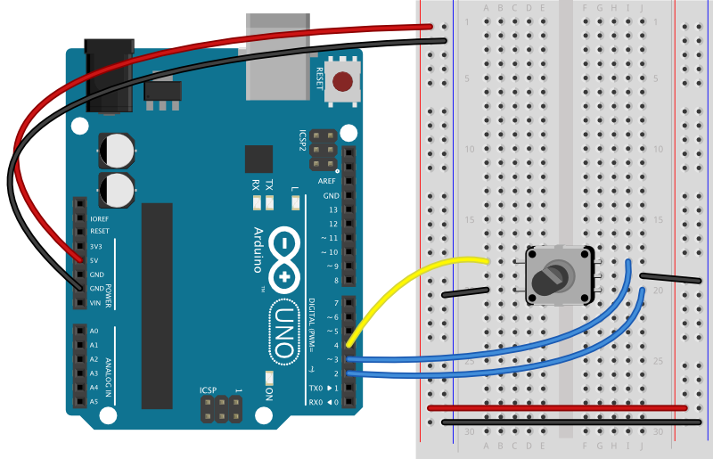
Figure 10. Breadboard view of an Arduino Uno attached to two potentiometers and a pushbutton. The potentiometers’ center pins are connected to the Arduino’s A0 and A1 inputs, respectively. Their left pins are connected to the voltage bus, and the right pins are connected to the ground bus, respectively. The pushbutton is connected from the Arduino’s voltage output to pin D2. a 10-kilohm connects the junction of the switch and pin D2 to ground.
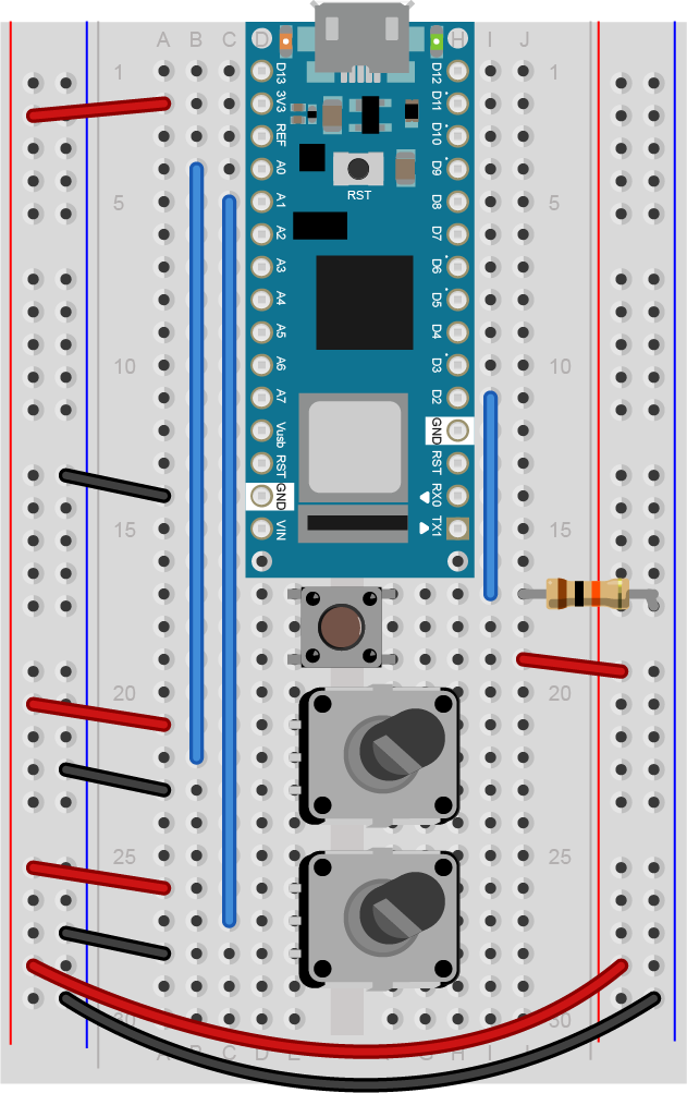
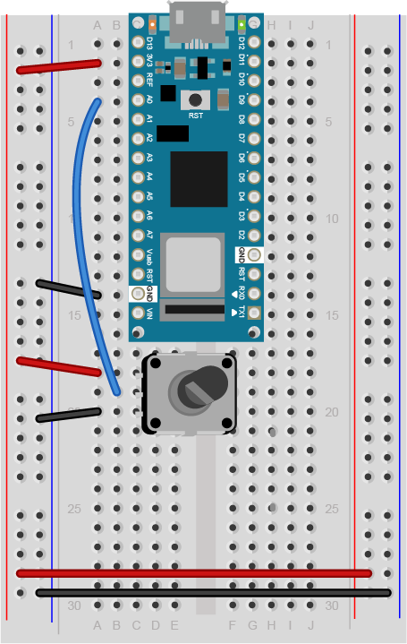
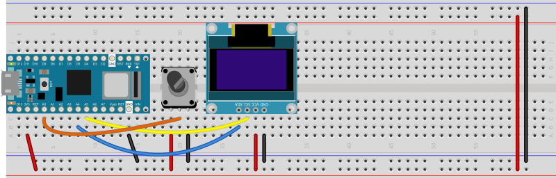
Figure 11. Breadboard view of an Arduino Nano attached to two potentiometers and a pushbutton. The potentiometers’ center pins are connected to the Arduino’s A0 and A1 inputs, respectively. Their left pins are connected to the voltage bus, and the right pins are connected to the ground bus, respectively. The pushbutton is connected from the Arduino’s voltage output to pin D2. a 10-kilohm connects the junction of the switch and pin D2 to ground.
You’re going to program the microcontroller to read the pushbutton and two analog sensors just like you did in the Intro to Serial Communications Lab. When you have to send multiple data items, you need a way to separate them. If you’re sending them as ASCII-encoded strings, it’s simple: you can just put non-numeric punctuation bytes between them (like a comma or a space) and a unique termination punctuation at the end (like a newline and/or carriage return).
This program will send the two analog sensor values and then the pushbutton. All three will be ASCII-encoded numeric strings, separated by commas. The whole line of sensor values will be terminated by carriage return (\r, ASCII 13) and newline (\n, ASCII 10).
const int buttonPin = 2;      // digital input

void setup() {
  // configure the serial connection:
  Serial.begin(9600);
  // configure the digital input:
  pinMode(buttonPin, INPUT);
}

void loop() {
  // read the first analog sensor:
  int sensorValue = analogRead(A0);
  // print the results:
  Serial.print(sensorValue);
  Serial.print(",");

  // read the second analog sensor:
  sensorValue = analogRead(A1);
  // print the results:
  Serial.print(sensorValue);
  Serial.print(",");

  // read the button:
  sensorValue = digitalRead(buttonPin);
  // print the results:
  Serial.println(sensorValue);
}
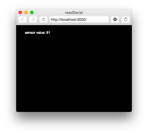
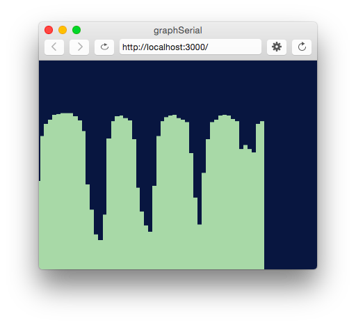
When you run this and output it to the Serial Monitor, you should see something like this:
Turn the potentiometers (or tweak the analog sensors) and push the button. Now you’ve got a data format: three sensors, comma-separated, terminated by carriage return and newline. This means that you already have an algorithm for how you’re going to program p5.js to read the serial input. You’ll see that algorithm in the next section.
Receive the data in P5.js
Now write a P5.js sketch that reads the data as formatted by the Arduino program above. The setup will be the same as it was in the Serial Input to p5.js using WebSerial lab. The checklist from that lab lays out all the important parts you need.
The sketch you’re going to write will:
Read the incoming serial data into a string until a carriage return and newline appear
split the string into substrings on the commas
convert the substrings into numbers
assign the numbers to variables to change your programNow that you’ve got a plan, put it into action.
Make a P5.js sketch. If you’re using the p5.js web editor, make a new sketch. Click the Sketch Files tab, and then choose the index.html file. Edit the head of the document as you did for the other p5.webserial labs. It should look like this:
The setup of your sketch will initialize the P5.webserial library and define your callback functions for serial events as you did in other sketches. It should look like this:
// variable to hold an instance of the p5.webserial library:
const serial = new p5.WebSerial();

// HTML button object:
let portButton;
let inData;                      // for incoming serial data
let outData;                     // for outgoing data

function setup() {
  createCanvas(400, 300);          // make the canvas
  // check to see if serial is available:
  if (!navigator.serial) {
    alert("WebSerial is not supported in this browser. Try Chrome or MS Edge.");
  }
  // if serial is available, add connect/disconnect listeners:
  navigator.serial.addEventListener("connect", portConnect);
  navigator.serial.addEventListener("disconnect", portDisconnect);
  // check for any ports that are available:
  serial.getPorts();
  // if there's no port chosen, choose one:
  serial.on("noport", makePortButton);
  // open whatever port is available:
  serial.on("portavailable", openPort);
  // handle serial errors:
  serial.on("requesterror", portError);
  // handle any incoming serial data:
  serial.on("data", serialEvent);
  serial.on("close", makePortButton);
}
function draw() {

}

// if there's no port selected,
// make a port select button appear:
function makePortButton() {
  // create and position a port chooser button:
  portButton = createButton('choose port');
  portButton.position(10, 10);
  // give the port button a mousepressed handler:
  portButton.mousePressed(choosePort);
}

// make the port selector window appear:
function choosePort() {
  serial.requestPort();
}

// open the selected port, and make the port
// button invisible:
function openPort() {
  // wait for the serial.open promise to return,
  // then call the initiateSerial function
  serial.open().then(initiateSerial);

  // once the port opens, let the user know:
  function initiateSerial() {
    console.log("port open");
  }
  // hide the port button once a port is chosen:
  if (portButton) portButton.hide();
}

// read any incoming data as a byte:
function serialEvent() {

}

// pop up an alert if there's a port error:
function portError(err) {
  alert("Serial port error: " + err);
}

// try to connect if a new serial port
// gets added (i.e. plugged in via USB):
function portConnect() {
  console.log("port connected");
  serial.getPorts();
}

// if a port is disconnected:
function portDisconnect() {
  serial.close();
  console.log("port disconnected");
}
Change the serialEvent() function to read the incoming serial data as a string until it encounters a carriage return and newline (“\r\n”). Then check to see that the resulting string has a length greater than 0 bytes. If it does, use the split() function to split it in to an array of strings. If the resulting array is at least three elements long, you have your three sensor readings. The first reading is the first analog sensor, and can be mapped to the horizontal movement using the locH variable. The second is the second analog sensor and can be mapped to the locV variable. The third is the button. When it’s 0, set the circleColor variable equal to 255 and when it’s 1, set the variable to 0. Here’s how:
function serialEvent() {
  // read a string from the serial port
  // until you get carriage return and newline:
  var inString = serial.readStringUntil("\r\n");
  //check to see that there's actually a string there:
  if (inString) {
    // split the string on the commas:
    var sensors = split(inString, ",");
    if (sensors.length > 2) {
      // if there are three elements
      // element 0 is the locH:
      locH = map(sensors[0], 0, 1023, 0, width);
      // element 1 is the locV:
      locV = map(sensors[1], 0, 1023, 0, height);
      // element 2 is the button:
      circleColor = 255 - sensors[2] * 255;
    }
  }
}
Note the mappings of sensors[0] and sensors[1]. If you’re not using potentiometers as the first two inputs on your Arduino, then you should use the input mappings for your sensors instead of 0 and 1023. If your analog values are greater than the width of the sketch or the height, the circle will be offscreen, which is why you have to map your sensor range to the screen size.
Program the draw() function to draw a circle that’s dependent on three global variables, locH, locV, and circleColor. Add these three globals to the top of the program:
// variables for the circle to be drawn:
let locH, locV;
let circleColor = 255;
Finally, here is the draw function:
function draw() {
  background(0);               // black background
  fill(circleColor);           // fill depends on the button
  ellipse(locH, locV, 50, 50); // draw the circle
}
If you run this, you should see the circle moving onscreen whenever you change your sensors. When you press the pushbutton, the circle will disappear. Okay, it’s not exactly a mouse, but you are controlling an animation from a device that you built.
Flow Control: Call and Response (Handshaking)
You’ve seen now that by coming up with a serial format (called a protocol), you can write the algorithm for receiving it even before you see any data. You can send multiple pieces of data this way, as long as you format it consistently.
Sometimes you can run into a problem when the sender sends faster than the receiver can read. When this happens, the receiver program slows down as the serial buffer fills up. You can manage this by implementing some form of flow control. The simplest way do to this is using a call-and-response method, where the sending program only sends when it’s told to do so, and the receiving program has to request new data every time it finishes reading what it’s got.
You can add handshaking to the code above fairly simply. Modify the Arduino code as follows. First, add a a new block of code in the setup() This block sends out a message until it gets a byte of data from the remote computer:
void setup() {
  Serial.begin(9600);
  while (Serial.available() <= 0) {
    Serial.println("hello"); // send a starting message
    delay(300);              // wait 1/3 second
  }
}
Now, modify the loop() by adding an if() statement to look for incoming serial data and read it.
void loop() {
  if (Serial.available() > 0) {
    // read the incoming byte:
    int inByte = Serial.read();
    // read the sensor:
    int sensorValue = analogRead(A0);
    // print the results:
    Serial.print(sensorValue);
    Serial.print(",");

    // read the sensor:
    sensorValue = analogRead(A1);
    // print the results:
    Serial.print(sensorValue);
    Serial.print(",");

    // read the sensor:
    sensorValue = digitalRead(buttonPin);
    // print the results:
    Serial.println(sensorValue);
  }
}
The rest of the sketch remains the same. When you run this and open the serial monitor, you’ll see:
hello
hello
hello
hello
Type any character in the output box and click Send. You’ll get a string of sensor values at the end of your hellos:
510,497,0
Type another character and click Send. It doesn’t matter what character you send, but the loop will always wait for an incoming byte before sending a new set of sensor values. When you write a program to receive this format, it just has to behave the same way you did:
Open the serial port
Wait for a hello
Send a byte to request data
Begin loop:
Wait for one set of data
Send a byte to request new data
end loop
Next, modify the P5.js sketch. Most of the changes are in the serialEvent() function. The initial “hello” messages will trigger this function, so when you get a “hello” or any other string, you need to send a byte back so that the Arduino has a byte available to read. Here’s the new serialEvent():
function serialEvent() {
  // read a string from the serial port
  // until you get carriage return and newline:
  var inString = serial.readStringUntil("\r\n");
  //check to see that there's actually a string there:
  if (inString) {
    if (inString !== "hello") {
      // if you get hello, ignore it
      // split the string on the commas:
      var sensors = split(inString, ",");
      if (sensors.length > 2) {
        // if there are three elements
        // element 0 is the locH:
        locH = map(sensors[0], 0, 1023, 0, width);
        // element 1 is the locV:
        locV = map(sensors[1], 0, 1023, 0, height);
        // element 2 is the button:
        circleColor = 255 - sensors[2] * 255;
        // send a byte back to prompt for more data:
        serial.print('x');
      }
    }
  }
}
You also need to add a line to the initiateSerial() function (which is inside the openPort() function) like so:
 function initiateSerial() {
    console.log("port open");
    // send a byte to start the microcontroller sending:
    serial.print("x");
  }
The reason for this is that if your Arduino is still in the setup() waiting for a byte to arrive, then it needs p5.js to send something when the port is opened. If the Arduino has already broken out of the loop (let’s say you opened the Serial monitor to check), then it is waiting for a byte from p5.js to send the next block of code. Whether it’s in the initiateSerial() function or at the end of the serialEvent() function, by sending a byte when you know the port has just been opened in p5.js, you force the Arduino to send you new data.
That’s it. Your sketch should still run just as it did before, though the serial communication is managed better now, because Arduino’s only sending when P5.js is ready to receive.
You can see the sketch running on GitHub at this link. You can see the source files for copying into the p5.js editor at this link.
Advantages of Raw Binary vs. ASCII
All the examples shown here sent the sensor values as ASCII-encoded strings. As mentioned above, that means you sent three bytes to send a three-digit value. If that same value was less than 255, you could send it in one raw binary byte. So ASCII is definitely less efficient. However, it’s more readable for debugging purposes, and if the receiving program is well-suited to convert strings to numbers, then ASCII is a good way to go. If the receiver’s not so good at converting strings to numbers (for example, it’s more challenging to read a multiple byte string in Arduino than in Processing) then you may want to send your data as binary values.
Advantages of Punctuation or Call-and-Response
The punctuation method for sending multiple serial values may seem simpler, but it has its limitations. You can’t easily use it to send binary values, because you need to have a byte with a unique value for the punctuation. In the example above, you’re using the value 10 (ASCII newline) as punctuation, so if you were sending your sensor values as raw bytes, you’d be in trouble when the sensor’s value is 10. The receiver would interpret the 10 as punctuation, not as a sensor value. In contrast, call-and-response can be used whether you’re sending data as raw binary values or as ASCII-encoded values.
Sometimes the receiver reads serial data slower than the sender sends it. For example, if you have a program that does a lot of graphic work, it may only read serial data every few milliseconds. The serial buffer will get full in that case, you’ll notice a lag in response time. This is when it’s good to switch to a call-and-response method.
Build an Application of Your Own
You just duplicated the basic functionality of a mouse; that is, a device with two analog sensors that affect X and Y, and a digital sensor (mouse button). What applications can you think of that could use a better physical interface for a mouse? A video editor that scrubs forward and back when you tilt a wand? An action game that reacts to how hard you hit a punching bag? An instructional presentation that speeds up if you shift in your chair too much? A music program driven by a custom musical instrument that you design?
Create a prototype in Arduino and P5.js, Node.js, Processing, or whatever programming environment you choose. Come up with a physical interface that makes it clear what actions map to what movements and actions. Figure out which actions can and should be possible at the same time. Present a working software and hardware model of your idea.
In this lab you’ll learn how to send data from p5.js to a microcontroller using asynchronous serial communication.
Overview
When you use the p5.webserial library for P5.js, it uses the W3C’s WebSerial API to allow your browser to communicate with serial ports on your computer. This lab shows you how to use P5 to control a microcontroller using asynchronous serial communication. WebSerial is currently only available in the Chrome and Chromium browsers and the Microsoft Edge browser, so make sure you’re using one of those to do this lab.
Figure 2. LEDs. Shown here are four LEDs. The one on the right is an RGB LED. You can tell this because it has four legs, while the others have only two legs.
Figure 3. Resistors. Shown here are 220-ohm resistors. You can tell this because they have two red and one brown band, followed by a gold band.
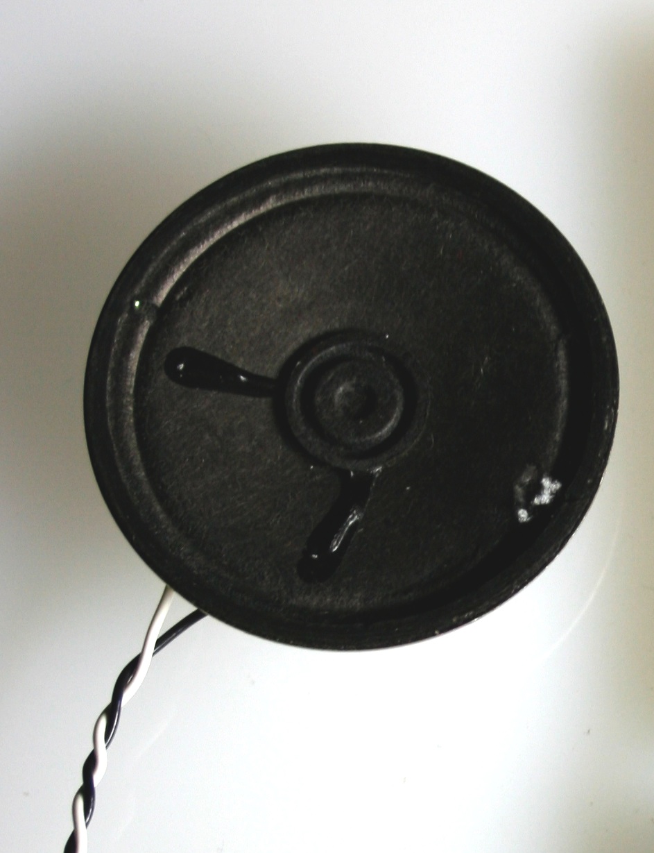
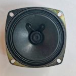
Figure 4. An 8 ohm speaker (optional).This is a good alternate to the LED if you prefer audible output.
Prepare the breadboard
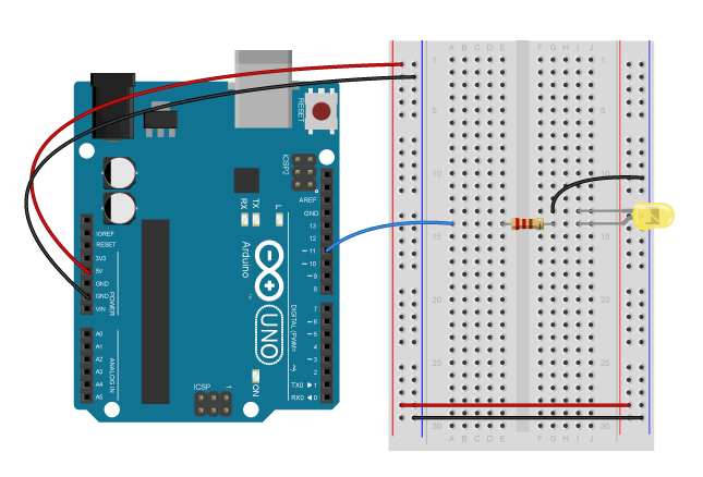
Connect power and ground on the breadboard to power and ground from the microcontroller. On the Arduino Uno, use the 5V and any of the ground connections. On the Nano, use 3.3V and the ground connections:
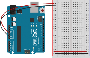
Figure 5. An Arduino Uno on the left connected to a solderless breadboard, right.
Figure 6. Breadboard view of an Arduino Nano mounted on a breadboard.
The +3.3 volts and ground pins of the Arduino Nano are connected by red and black wires(Figure 6), respectively, to the left side rows of the breadboard. +3.3 volts is connected to the left outer side row (the voltage bus) and ground is connected to the left inner side row (the ground bus). The side rows on the left are connected to the side rows on the right using red and black wires, respectively, creating a voltage bus and a ground bus on both sides of the board.Figure 5. Breadboard view of an Arduino Nano connected to a breadboard. The +3.3 volts and ground pins of the Arduino are connected by red and black wires, respectively, to the left side rows of the breadboard. +3.3 volts is connected to the left outer side row (the voltage bus) and ground is connected to the left inner side row (the ground bus). The side rows on the left are connected to the side rows on the right using red and black wires, respectively, creating a voltage bus and a ground bus on both sides of the board.
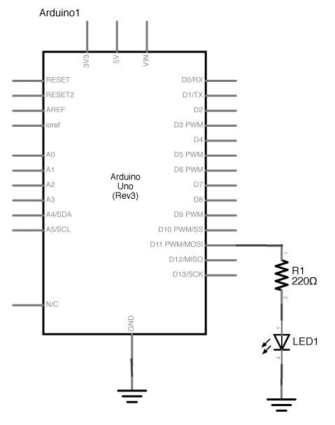
Connect the LED and resistor to digital I/O pin 11 of the module(Figure 7-8). Alternately, you can replace the 220-ohm LED with a speaker (Figure 9-10). You’ll find code below that uses tones instead of LEDs where appropriate. For more on how to do that, see the Tone Output lab:
Figure 7. Schematic view of an Arduino connected to an LED.
Figure 8. Breadboard view of an Arduino connected to an LED.
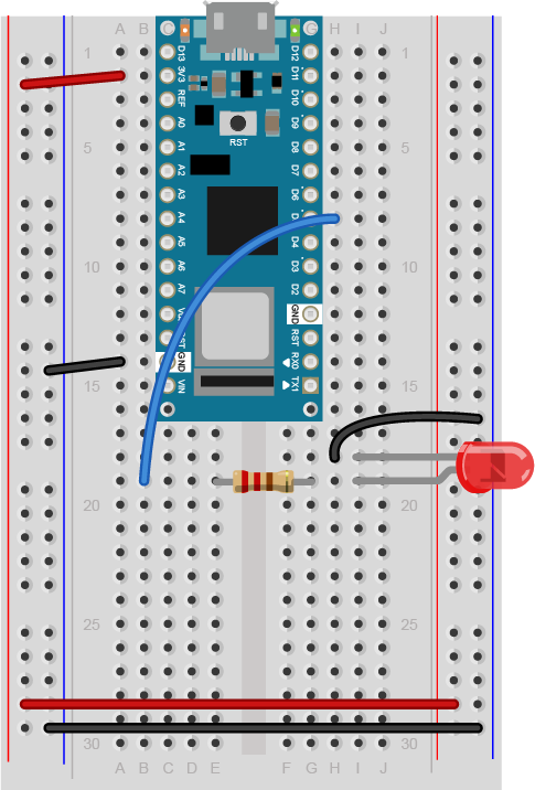
Figure 9. Breadboard view of an LED connected to digital pin 5 of an Arduino Nano.
Figure 9 shows a breadboard view of an LED connected to digital pin 5 of an Arduino Nano. The Nano straddles the center of the breadboard in the first fifteen rows. The Nano’s voltage pin (physical pin 2) connects to the board’s voltage bus, and the Nano’s ground pin (physical pin 14) connects to the board’s ground bus. The LED is in the right center of the board, with its anode in one row and the cathode in the next. A 220-ohm resistor connects the LED’s anode to a wire connecting to digital pin 5. The LED’s cathode is connected to the ground bus.
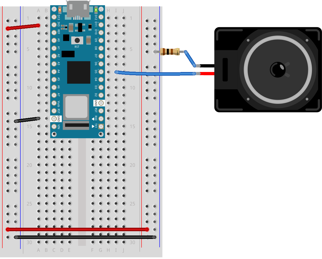
Figure 10. Breadboard view of an Arduino Nano connected to a speaker to digital pin 5.
Figure 10 shows a breadboard view of an Arduino Nano connected to a speaker. The Nano’s ground (physical pin 14) is connected to the ground bus of the breadboard as usual. The red positive wire of the speaker is connected to digital pin 5 of the Arduino. The black ground wire of the speaker is connected to one leg of a 100 ohm resistor. The other leg of the resistor connects to ground.
Program the Microcontroller
Program your Arduino to read the analog input as follows:
void setup() {
  Serial.begin(9600);     // initialize serial communications
  pinMode(5, OUTPUT);
}

void loop() {
  if (Serial.available() > 0) { // if there's serial data available
    int inByte = Serial.read();   // read it
    Serial.write(inByte);         // send it back out as raw binary data
    analogWrite(5, inByte);       // use it to set the LED brightness
    // if you're using a speaker instead of an LED, uncomment line below  and comment out the previous line:
    //  tone(5, inByte*10);     // play tone on pin 5
  }
}
Only one port at a time can access a serial port.
As you work on this any microcontroller-to-computer application, you will be switching back and forth between the app that programs the microcontroller (in this case, the Arduino IDE) and the app that the microcontroller is communicating with (in this case, p5.js in the browser). You have to keep in mind that only one of these at a time can access a serial port.
That means that when you want to reprogram your Arduino from the Arduino IDE, you should to stop your sketch in the browser window to do so. Then, restart the browser sketch when you’re done reprogramming the Arduino. You don’t need to quit the Arduino IDE each time, because it knows to release the serial port when it’s not programming. However, you do need to close the Serial Monitor in the Arduino IDE when you are using WebSerial in the browser.
The P5.js WebSerial Library
To communicate with your microcontroller serially, you’re going to use the P5.js WebSerial library. If you’re using the p5.js web editor, make a new sketch. Click the Sketch Files tab, and then choose the index.html file. In the head of the document, look for this line:
The sketch you’re going to write will control the microcontroller’s LED from P5.js. Dragging the mouse up and down the canvas will dim or brighten the LED, and typing 0 through 9 will set the LED’s brightness in increments from off (0) through almost full brightness (9). There’s an alternate sketch that will make changing tones if you prefer that instead of a changing LED. The sketch will also receive serial input from the microcontroller just as in the WebSerial Input to P5.js lab, so that you can see that the microcontroller is getting the same values you’re sending.
The setup of your sketch will initialize the P5.webserial library and define your callback functions for serial events. Program the global variables and setup() function as follows:
// variable to hold an instance of the p5.webserial library:
const serial = new p5.WebSerial();

// HTML button object:
let portButton;
let inData;                            // for incoming serial data
let outByte = 0;                       // for outgoing data

function setup() {
  createCanvas(400, 300);          // make the canvas
  // check to see if serial is available:
  if (!navigator.serial) {
    alert("WebSerial is not supported in this browser. Try Chrome or MS Edge.");
  }
  // if serial is available, add connect/disconnect listeners:
  navigator.serial.addEventListener("connect", portConnect);
  navigator.serial.addEventListener("disconnect", portDisconnect);
  // check for any ports that are available:
  serial.getPorts();
  // if there's no port chosen, choose one:
  serial.on("noport", makePortButton);
  // open whatever port is available:
  serial.on("portavailable", openPort);
  // handle serial errors:
  serial.on("requesterror", portError);
  // handle any incoming serial data:
  serial.on("data", serialEvent);
  serial.on("close", makePortButton);
}

function draw() {

}
For now you’re leaving the draw() function empty. You’ll fill it in later. You’ll be adding some functions to read mouse dragging and key pressing as well.
// if there's no port selected,
// make a port select button appear:
function makePortButton() {
  // create and position a port chooser button:
  portButton = createButton("choose port");
  portButton.position(10, 10);
  // give the port button a mousepressed handler:
  portButton.mousePressed(choosePort);
}

// make the port selector window appear:
function choosePort() {
  serial.requestPort();
}

// open the selected port, and make the port
// button invisible:
function openPort() {
  // wait for the serial.open promise to return,
  // then call the initiateSerial function
  serial.open().then(initiateSerial);

  // once the port opens, let the user know:
  function initiateSerial() {
    console.log("port open");
  }
  // hide the port button once a port is chosen:
  if (portButton) portButton.hide();
}

// read any incoming data as a byte:
function serialEvent() {
  // read a byte from the serial port:
  var inByte = serial.read();
  // store it in a global variable:
  inData = inByte;
}

// pop up an alert if there's a port error:
function portError(err) {
  alert("Serial port error: " + err);
}

// try to connect if a new serial port
// gets added (i.e. plugged in via USB):
function portConnect() {
  console.log("port connected");
  serial.getPorts();
}

// if a port is disconnected:
function portDisconnect() {
  serial.close();
  console.log("port disconnected");
}

function closePort() {
  serial.close();
}
Program the draw() function to display the value of any incoming serial bytes. Here it is:
function draw() {
  // black background, white text:
  background(0);
  fill(255);
  // display the incoming serial data as a string:
  text("incoming value: " + inData, 30, 30);
}
To read the mouse and keyboard, you’ll need to write functions to respond to the ‘mouseDragged’ and ‘keyPressed’ events. ‘MouseDragged’ will happen whenever you click and drag the mouse on the canvas. When that happens, read the mouseY, and map its position on the canvas to a value from 0 to 255. Convert the result to a number using the int() function. Then send it out the serial port using the serial.write() function:
function mouseDragged() {
  // map the mouseY to a range from 0 to 255:
  outByte = byte(map(mouseY, 0, height, 0, 255));
  // send it out the serial port:
  serial.write(outByte);
}
The serial.write() function is versatile. If you give it a variable or literal that’s a numeric data type, it will send it as its raw binary value. In the code above, note how you’re converting the output of the map() function to a number using the int() function. If you give it a string, however, it will send out that ASCII string. So be aware of the difference, and make sure you know whether your serial receiving device wants raw binary or ASCII-encoded data.
Program the keyPressed() function similarly to the mouseDragged() function. You want it to read the key strokes, convert them to raw bytes, and send them out the serial port. But you only want to send them if they key hit was 0 through 9. The P5.js variable key returns a numeric value, so you can do math on it and convert it like so:
function keyPressed() {
  if (key >= 0 && key <= 9) { // if the user presses 0 through 9
    outByte = (key * 25); // map the key to a range from 0 to 225
    serial.write(outByte); // send it out the serial port
  }
}
That’s all you want your sketch to do, so try running it now. You should see that the initial incoming serial value is undefined, but when you drag the mouse up and down, or type 0 through 9, it will update when the Arduino program returns what it received. The LED will also change with these actions.
You can see this sketch running on gitHub at this link. You can get the full text of it at this link.
Sending ASCII-Encoded Serial Data
When you send data from p5.js using p5.webserial, the serial.write() function works like it does in Arduino: it sends numbers as binary data. In the programs above, you’re sending binary data from p5.js and reading it as binary in Arduino.
If you want to send ASCII-encoded serial data from P5.js instead, all you have to do is to serial.print() or serial.println() your string. On the Arduino side, you can read single characters one byte at a time simply as well. However, if you want to convert multi-byte number strings to numeric values, you’ll need a new function to read ASCII encoded numeric strings called parseInt().
Program the Microcontroller Again
To start off with, load a sketch from the Arduino examples called PhysicalPixel. You can find it in the File Menu -> Examples -> Communication -> PhysicalPixel. Here’s what it looks like. Change the LED pin number to pin 5 as follows:
const int ledPin = 5; // the pin that the LED is attached to
int incomingByte;     // a variable to read incoming serial data into

void setup() {
  Serial.begin(9600);             // initialize serial communication
  pinMode(ledPin, OUTPUT);        // initialize the LED pin as an output
}

void loop() {
  if (Serial.available() > 0) { // see if there's incoming serial data
    incomingByte = Serial.read(); // read it
    if (incomingByte == 'H') {    // if it's a capital H (ASCII 72),
      digitalWrite(ledPin, HIGH); // turn on the LED
      // if you're using a speaker instead of an LED, uncomment line below  and comment out the previous line:
      //  tone(5, 440);           // play middle A on pin 5
    }
    if (incomingByte == 'L') {    // if it's an L (ASCII 76)
      digitalWrite(ledPin, LOW);  // turn off the LED
      // if you're using a speaker instead of an LED, uncomment line below  and comment out the previous line:
      // noTone(5);
    }
  }
}
When you run this, open the serial monitor and type H or L, and the LED will go on or off. Try typing h or l instead. The LED won’t change, because H and h have different ASCII values, as do L and l. But you can see from this that you don’t need to memorize the ASCII chart to check for character values in your code. Put the character you want to read in single quotes, and the Arduino compiler will automatically convert the character to its ASCII value for you. It only works for single characters, though.
Program P5.js To Control the LED
To get P5.js to control this Arduino program serially, you only need to add to the keyPressed() function to read H or L in addition to 0 through 9. Here’s your new mousePressed() function:
function keyPressed() {
  if (key >= 0 && key <= 9) {
    // if the user presses 0 through 9
    outByte = byte(key * 25); // map the key to a range from 0 to 225
    serial.write(outByte); // send it out the serial port
  }
  if (key === "H" || key === "L") {
    // if the user presses H or L
    serial.write(key); // send it out the serial port
  }
}
Because the key is already a single character, P5.js sends it out as is, and Arduino reads it as a single byte, looking for the ASCII value of H or L. Notice how the values returned to P5.js are 72 and 76, the ASCII values for H and L. For single characters like this, exchanging data is simple.
If you tried to change the LED with the mouse, you didn’t see anything happen unless your output value was 72 or 76. Why is that?
To see the sketch running on GitHub at this link. You can see the source files for copying into the p5.js editor at this link.
Processing ASCII-Encoded Strings With Arduino
It is also possible to read and interpret ASCII-encoded strings in Arduino. The String.parseInt() function reads an incoming string until it finds a non-numeric character, then converts the numeric string that it read into a long integer. This is a blocking function, meaning that String.parseInt() stops the program and does nothing until it sees a non-numeric character, or until a timeout passes. The timeout is normally one second (or 1000 milliseconds), but you can set it to a lower number of milliseconds using Serial.setTimeout(). Here’s a variation on the original Arduino sketch from above, using Serial.parseInt() this time:
void setup() {
  Serial.begin(9600);    // initialize serial communications
  Serial.setTimeout(10); // set the timeout for parseInt
  pinMode(5, OUTPUT);
}

void loop() {
  if (Serial.available() > 0) { // if there's serial data available
    int inByte = Serial.parseInt(); // read it
    if (inByte > 0) {
      Serial.write(inByte);      // send it back out as raw binary data
      analogWrite(5, inByte);    // use it to set the LED brightness
      // if you're using a speaker instead of an LED, uncomment line below  and comment out the previous line:
      //  tone(5, inByte*10);     // play tone on pin 5
    }
  }
}
Upload this to your microcontroller, then open the Serial Monitor and send in some ASCII numeric strings. You’ll see the character that’s represented by the string’s value. For example, 65 will return A, 34 will return “, and so forth.Notice that this version of the sketch has a conditional statement to check if the incoming byte is 0. This is because of a quirk of the parseInt() function. It returns 0 if the timeout is hit, or if the string is legitimately 0. This means you can’t really parse for a string like this: "0\n".
Program p5.js To Send a String
Now that your microcontroller is expecting a string, program P5.js to send one. This means changing the mouseDragged() function. Program it to print a string with a newline at the end using the serial.println() command like so:
serial.println(outByte);
Since the newline added at the end by serial.println() is a non-numeric character, the Serial.parseInt() function will see it and parse the string, not waiting for the timeout.
To see the sketch running on GitHub at this link. You can see the source files for copying into the p5.js editor at this link.
Conclusion
When you’re sending data between two computers using asynchronous serial communication, you have to make sure that what the sender is sending is formatted the same as what the receiver is listening for. See Table 1 to review what are suitable data formats for different types/sizes of data and which functions to use on p5.js and Arduino for serial communication.
Number of Bytes
1 Byte
Multi Bytes
Data to Send
A single number < 255
A single character
A single number > 255, multiple values
Send as:
Binary
Ascii
Ascii
p5.js ->
serial.write(integer)
serial.write(string)
serial.write
(valueToSend + ",")
-> Arduino
Serial.read()
Serial.parseInt()
Table 1. Serial Communication: p5.js to Arduino
Think this out in advance before you code, then consider what functions you’ve got on both computers to convert data from strings to raw binary numbers and back. Test with fixed values at first, so you know you’re getting what you think you should. For example, sending an ASCII-encoded numeric string like this:
1023\n
Will always result in these six bytes:
49 48 50 51 10
Likewise, this text string:
Hello\n
will always be:
72 101 108 108 111 10
By sending a string you know both the ASCII and raw binary representations of, you can test your code easier, because what you’re sending won’t change. Once you know the sending and receiving works, then you can send variable strings.
The more you work with serial data, the more you’ll become familiar with the methods for handling it.
This lab uses a p5.js library called p5.WebSerial to make it easy in p5.js. In this lab, you’ll generate an analog output value from a potentiometer, then send that value via asynchronous serial communication to P5.js. You’ll use that value in P5.js to draw a graph.
Web browsers have traditionally been designed to be separate from the rest of a computer’s operating system, not able to connect to the computer’s hardware ports for security reasons. Recently, however, the W3C developed the WebSerial API in JavaScript, which allows browsers to communicate with a computer’s serial ports. WebSerial is currently only available in the Chrome and Chromium browsers and the Microsoft Edge browser, so make sure you’re using one of those to do this lab.
To get the most out of this tutorial, you should know what a microcontroller is and how to program them. You should also understand asynchronous serial communication between microcontrollers and personal computers. You should also understand the basics of P5.js.
Once you gain an understanding of serial communication, you can use any program that can connect with your computer’s serial ports to communicate with a microcontroller. In addition to the WebSerial API you’ll see here, you can use other programming environments to communicate serially. Processing, Max/MSP, and OpenFrameworks are three other popular multimedia programming environments that can communicate via the serial ports. You can also do this with Unity, Unreal, or any other programming environment that can access the serial ports.
Figures 1-4 below show the parts you’ll need for this exercise. Click on any image for a larger view.
Figure 1. Microcontroller. Shown here is an Arduino Nano 33 IoT
Figure 2. Jumper wires. You can also use pre-cut solid-core jumper wires.
Figure 3. A solderless breadboard
Figure 4. Potentiometer
Prepare the Breadboard
For this exercise you’re going to attach a potentiometer as an analog input to your microcontroller, and send the sensor’s reading serially to p5.js via the p5.serialcontrol app.
Connect power and ground on the breadboard to the microcontroller. On the Arduino module, use the 5V or 3.3V (depending on your model) and any of the ground connections. Figures 5 and 6 show connections for an Arduino Uno and a Nano, respectively.
Figure 5. An Arduino Uno on the left connected to a solderless breadboard, right.
The Uno’s 5V output hole is connected to the red column of holes on the far left side of the breadboard (Figure 5). The Uno’s ground hole is connected to the blue column on the left of the board. The red and blue columns on the left of the breadboard are connected to the red and blue columns on the right side of the breadboard with red and black wires, respectively. These columns on the side of a breadboard are commonly called the buses. The red line is the voltage bus, and the black or blue line is the ground bus.
Figure 6. Breadboard view of an Arduino Nano mounted on a breadboard.
Images made with Fritzing, a circuit drawing application
The Nano is mounted at the top of the breadboard (Figure 6), straddling the center divide, with its USB connector facing up. The top pins of the Nano are in row 1 of the breadboard.
The Nano, like all Dual-Inline Package (DIP) modules, has its physical pins numbered in a U shape, from top left to bottom left, to bottom right to top right. The Nano’s 3.3V pin (physical pin 2) is connected to the left side red column of the breadboard. The Nano’s GND pin (physical pin 14) is connected to the left side black column. These columns on the side of a breadboard are commonly called the buses. The red line is the voltage bus, and the black or blue line is the ground bus. The blue columns (ground buses) are connected together at the bottom of the breadboard with a black wire. The red columns (voltage buses) are connected together at the bottom of the breadboard with a red wire.
Add a Potentiometer
Connect a potentiometer to analog in pin 0 of the module. Figure 7 shows the schematic and figures 8 and 9 show the potentiometer connected to an Arduino and Nano, respectively.
Figure 7. Schematic view of a potentiometer connected to analog in 0 of the Arduino
Figure 8. Breadboard view of a potentiometer connected to analog in 0 of an Arduino. The potentiometer is connected to three rows in the left center section of the breadboard. The two outside pins are connected to voltage and ground. The center pin is connected to the Arduino’s analog in 0.
Figure 9. Breadboard view of a potentiometer connected to analog in 0 of an Arduino Nano. The Nano is connected as usual, straddling the first fifteen rows of the breadboard with the USB connector facing up. Voltage (physical pin 2) is connected to the breadboard’s voltage bus, and ground (physical pin 14) is connected to the breadboard’s ground bus. The potentiometer is connected to three rows in the left center section of the breadboard. The two outside pins are connected to voltage and ground. The center pin is connected to the Nano’s analog in 0.
Program the Microcontroller
Program your Arduino to read the analog input as follows:
void setup() {
  Serial.begin(9600); // initialize serial communications
}

void loop() {
  // read the input pin:
  int potentiometer = analogRead(A0);
  // remap the pot value to fit in 1 byte:
  int mappedPot = map(potentiometer, 0, 1023, 0, 255);
  // print it out the serial port:
  Serial.write(mappedPot);
  // slight delay to stabilize the ADC:
  delay(1);
}
Only one port at a time can access a serial port.
As you work on this any microcontroller-to-computer application, you will be switching back and forth between the app that programs the microcontroller (in this case, the Arduino IDE) and the app that the microcontroller is communicating with (in this case, p5.js in the browser). You have to keep in mind that only one of these at a time can access a serial port.
That means that when you want to reprogram your Arduino from the Arduino IDE, you should to stop your sketch in the browser window to do so. Then, restart the browser sketch when you’re done reprogramming the Arduino. You don’t need to quit the Arduino IDE each time, because it knows to release the serial port when it’s not programming. However, you do need to close the Serial Monitor in the Arduino IDE when you are using WebSerial in the browser.
The P5.js WebSerial Library
To communicate with your microcontroller serially, you’re going to use the P5.js WebSerial library. If you’re using the p5.js web editor, make a new sketch. Click the Sketch Files tab, and then choose the index.html file. In the head of the document, look for this line:
To start off, you need to know if WebSerial is supported in the browser you’re using. Open the sketch.js file and change it to the following:
// variable to hold an instance of the p5.webserial library:
const serial = new p5.WebSerial();

function setup() {
   // check to see if serial is available:
   if (!navigator.serial) {
    alert("WebSerial is not supported in this browser. Try Chrome or MS Edge.");
  }
}
When you run this p5.js sketch in a browser, you’ll get a message letting you know whether or not this browser supports WebSerial. In a browser that supports WebSerial, you may want to delete the else clause.
Serial Events
JavaScript, the language on which p5.js is based, relies heavily on events and callback functions. An event is generated by the operating system when something significant happens, like a serial port opening, or new data arriving in the port. In your sketch, you write a callback function to respond to that event. The p5.webserial library uses events and callback functions as well. It can listen for the following serialport events:
noport – when there is no selected serial port
portavailable – when a serial port becomes available
data – new data arrives in a serial port
close – the serial port is closed
requesterror – something goes wrong when you request a serial port.
The WebSerial API on which the p5.webserial library is based also has connect and disconnect events for when a serial port is physically disconnected (or in the case of a USB-native device like the Nano 33 IoT, when it is reset). You’ll see those below as well, and you’ll see them run whenever the serial connection to the Arduino is reset.
To use the the webserial library’s events, you need to set callback functions for them. Change your sketch to include a port chooser button and a variable for incoming data, then in the setup() function, add callbacks for open, close, and data, and error like so:
// variable to hold an instance of the p5.webserial library:
const serial = new p5.WebSerial();

// HTML button object:
let portButton;
let inData;                   // for incoming serial data
let outByte = 0;              // for outgoing data

function setup() {
  createCanvas(400, 300);          // make the canvas
  // check to see if serial is available:
  if (!navigator.serial) {
    alert("WebSerial is not supported in this browser. Try Chrome or MS Edge.");
  }
  // if serial is available, add connect/disconnect listeners:
  navigator.serial.addEventListener("connect", portConnect);
  navigator.serial.addEventListener("disconnect", portDisconnect);
  // check for any ports that are available:
  serial.getPorts();
  // if there's no port chosen, choose one:
  serial.on("noport", makePortButton);
  // open whatever port is available:
  serial.on("portavailable", openPort);
  // handle serial errors:
  serial.on("requesterror", portError);
  // handle any incoming serial data:
  serial.on("data", serialEvent);
  serial.on("close", makePortButton);
}

function draw() {


}
The draw() function is empty for the moment. You’ll come back and fill that in later.
Now that you’ve set listeners for the events, you need to add the callback functions. Here they are. Add these after the draw() function:
// if there's no port selected,
// make a port select button appear:
function makePortButton() {
  // create and position a port chooser button:
  portButton = createButton("choose port");
  portButton.position(10, 10);
  // give the port button a mousepressed handler:
  portButton.mousePressed(choosePort);
}

// make the port selector window appear:
function choosePort() {
  if (portButton) portButton.show();
  serial.requestPort();
}

// open the selected port, and make the port
// button invisible:
function openPort() {
  // wait for the serial.open promise to return,
  // then call the initiateSerial function
  serial.open().then(initiateSerial);

  // once the port opens, let the user know:
  function initiateSerial() {
    console.log("port open");
  }
  // hide the port button once a port is chosen:
  if (portButton) portButton.hide();
}

// pop up an alert if there's a port error:
function portError(err) {
  alert("Serial port error: " + err);
}
// read any incoming data as a string
// (assumes a newline at the end of it):
function serialEvent() {
  inData = Number(serial.read());
  console.log(inData);
}

// try to connect if a new serial port
// gets added (i.e. plugged in via USB):
function portConnect() {
  console.log("port connected");
  serial.getPorts();
}

// if a port is disconnected:
function portDisconnect() {
  serial.close();
  console.log("port disconnected");
}

function closePort() {
  serial.close();
}
Wait a Minute! Don’t I have to Set the Data Rate When I Open the Port?
In asynchronous serial communications, both computers have to set the same data rate in order to communicate. In Arduino, you set the data rate with Serial.begin(9600); In p5.webserial, 9600 bits per second is the default, so you don’t have to set the rate if you want 9600bps. But if you want to set the rate to another value, change your serial.open() call in the openPort() function as follows:
let options = { baudrate: 9600}; // change the data rate to whatever you wish
serial.open(portName, options);
There are other port options you can set using p5.webserial, including baudRate, bufferSize, dataBits, flowControl, parity and stopBits. These are all standard serialport options, and most programming environments which support serial communication will have them. You can get details of these in the p5.webserial documentation.
p5.WebSerial Sketch Checklist
Most p5.WebSerial sketches that you write will have a similar structure to this one. The main difference between them all will be how you read and interpret incoming serial data, and how and when you send and format outgoing serial data. Here’s a checklist of the pieces you’re likely to see in every sketch:
In the HTML file, include the p5.webserial library
In the global variables of the sketch,
make a new instance of the library
include a port selector button or some way to invoke the serial port chooser dialogue box
In the setup:
Make sure WebSerial is supported in this browser
Include a call to serial.getPorts() to check for available ports.
include serial.on() listeners for these events:
noport
portavailable
data
close
requesterror
include navigator listeners for connect and disconnect
Define handler functions for all of the events above. Most of these can be simple alerts or console.log messages
Customize the function that responds to the data listener (usually called serialEvent() in these examples), as you’ll see below.
Decide when and how you’ll send serial data out, as you’ll see in the other p5.webserial labs.
The last two items of this list are the ones on which you’ll spend most of your time. The rest of the items are things you’re likely to copy from one sketch to another.
Reading Incoming Serial Data
The event that that you’ll use the most is the data event, which calls the serialEvent() function. Each time a new byte arrives in the serial port, this function is called. Now it’s time to make serialEvent() do some work. Add a new global variable at the top of your sketch called inData like so:
The serialEvent() function you added above looks like this:
function serialEvent() {
  inData = Number(serial.read());
  console.log(inData);
}
It’s reading the incoming data byte by byte, and interpreting each byte as a number. That’s why the Number() function surrounds the read() function. Since you’re sending the data from the Arduino as a binary value (using the Serial.write() function), you have to interpret it in p5.js as a binary value as well.
Next, make the draw() function to print the sensor value to the screen like so:
Figure 10. A screenshot of the sketch running in a browser. The sketch prints the sensor value in text on the screen.
When you run your sketch now, you should get something like the sketch shown in Figure 10.
To see the sketch running on GitHub at this link. You can see the source files for copying into the p5.js editor at this link.
The sensor value onscreen should change as you turn your potentiometer. Congratulations! You’ve got P5.js talking to your microcontroller.
What’s Happening Here
Every time your microcontroller sends a byte serially using Serial.write(), the computer receives it and generates a ‘data’ event. Then your serialEvent() function is called. It reads the byte as a number, and stores it in the global variable inData. The draw() method just uses the latest value of inData in the text string it displays on the screen.
You may be wondering why you’re mapping the sensor value or dividing it by 4 in the Arduino sketch above. That’s because in order to send the sensor value as a single byte, it must be between 0 and 255, or no more than 28 bits.
P5.js Console.log() and Arduino delay(): a Tricky Combination
In testing this, you may have put a console.log() statement in the serialEvent() function in your P5.js sketch. When you did, you would have noticed that it causes a lag in the sketch, and the console.log() statements continue even after you stop the sketch. This is because the operating system keeps the incoming serial data in a buffer, and P5.js isn’t reading and printing it as fast as Arduino is sending it.
You might think, “Okay, then I’ll just put a delay() in my Arduino sketch to slow it down.” That’s a bad idea. When you put in a delay, it means you’re only reading your sensor when that delay is not running. You can miss critical sensor events while that delay is in progress. Even a relatively small delay, for example 30ms, can make it difficult to reliably read state changes in a switch or peaks in an analog sensor. Don’t use delays if you can avoid it. For more on how to handle the flow of serial data from Arduino to P5.js and back, see the Duplex Serial Flow using WebSerial in P5.js lab.
Draw a Graph With the Sensor Values
It would be useful to see a graph of the sensor values over time. You can do that by modifying the draw() method to draw the graph. To do this, add a new global variable at the top of your sketch called xPos. You’ll use this to keep track of the x position of the latest graph line:
let xPos = 0; // x position of the graph
Because of the way the graphing function below works, you can’t reset the background every time through the draw() loop. So take the background() command and put it in the setup() function instead of the draw(), as shown below. That way it runs once, then not again. As long as you’re at it, switch from black & white to a nice blue color:
function setup() {
  createCanvas(400, 300);
  background(0x08, 0x16, 0x40);
Now make a new function called graphData(). It’ll take a number value as a parameter, and it will draw a line on the screen that’s mapped to the number value. Then it will increment xPos so that the next line is drawn further along. It will also check if the xPos is at the right edge of the screen, and reset the screen by calling background() again if it is:
function graphData(newData) {
  // map the range of the input to the window height:
  var yPos = map(newData, 0, 255, 0, height);
  // draw the line in a pretty color:
  stroke(0xA8, 0xD9, 0xA7);
  line(xPos, height, xPos, height - yPos);
  // at the edge of the screen, go back to the beginning:
  if (xPos >= width) {
    xPos = 0;
    // clear the screen by resetting the background:
    background(0x08, 0x16, 0x40);
  } else {
    // increment the horizontal position for the next reading:
    xPos++;
  }
}
Finally, take everything out of the draw() function and just call graphData() from there:
function draw() {
  graphData(inData);
}
When you run the sketch now, you should get a graph, as shown in Figure 11.
Figure 11. Screenshot of the serial graph p5.js sketch. The sensor’s values are graphed on the screen
To see the sketch running on GitHub at this link. You can see the source files for copying into the p5.js editor at this link.
Reading Serial Data as a String
This works well if you want to read your sensor values as a single byte, but what if you want a larger range of numbers? What if you want the full 0 to 1023 that analogRead() can output instead of just 0 to 255? To do this, you need to send the data as an ASCII-encoded numeric string from the microcontroller, and you need to read and interpret the incoming data in P5 as an ASCII-encoded numeric string as well.
Change your Arduino program to the following:
void setup() {
 Serial.begin(9600); // initialize serial communications
}

void loop() {
 int potentiometer = analogRead(A0);                  // read the input pin
 int mappedPot = map(potentiometer, 0, 1023, 0, 255); // remap the pot value to fit in 1 byte
 Serial.println(mappedPot);                           // print it out the serial port
 delay(1);                                            // slight delay to stabilize the ADC
}
Now it will print the potentiometer’s value as an ASCII-encoded numeric string, and it will add a carriage return byte and a newline byte at the end, because that’s what println() does.
Once you’ve uploaded this to your Arduino, run your P5 sketch again. Try adding println(inData);at the end of your serialEvent() function. When your P5 sketch reads the data from this Arduino program, you get very low values, and every so often you see the value 10 followed by the value 13. What’s going on?
When a computer ASCII-encodes a number, it converts that number to a string of bytes, each of which is the ASCII value for a numeral in the number. For example, the number 865 gets converted to three bytes, as shown in Figure 12.
Figure 12. The decimal number 865 when sent serially as ASCII is three bytes long. The first byte representing digit, 8, has the ASCII value 58. The second byte representing the digit 6 has the ASCII value 54. The third byte representing the digit 5 has the ASCII value 53.
If there’s a carriage return byte and a newline byte after this, the string is five bytes, and the last two bytes’ values are 13 (carriage return, or \r in most programming languages) and 10 (newline or \n in most programming languages), respectively.
Your P5.js sketch is reading every byte’s value and graphing it. That’s why you get a graph of very low values, with a bunch of them being 13 and 10. The Arduino is ASCII-encoding the potentiometer values, but the P5 sketch is interpreting the bytes as if they’re not encoded that way.
Now change the serialEvent() function like so:
function serialEvent() {
  // read a byte from the serial port, convert it to a number:
  inData = serial.readLine();
}
Run it again. What’s changed? Now you’re getting a graph kind of like you were before. The serial.readLine();command reads the incoming serial data as a string, and when that string happens to be all-numeric, it converts it to a number. So you’re getting the ASCII-encoded string as a number again. But sometimes there are gaps. Why?
Remember, the ‘data’ event occurs every time a new byte comes in the serial port. Now that you’re sending an ASCII-encoded string, every potentiometer reading is several bytes long. So you only get a complete string every three to six bytes (three for “0\r\n” and six for “1023\r\n”). Sometimes, when the serialEvent() function calls serial.readLine(); it gets nothing. That’s when draw() draws the gaps. You need to change your function to check that the resulting string is actually a valid number before you put the string into inData. First, create a local variable to get the string, then check to see if the string’s length is greater than zero. If it is, then put it into inData so that the other functions in the sketch can use the new data. Here’s how you do that:
function serialEvent() {
  // read a string from the serial port:
  var inString = serial.readLine();
  // check to see that there's actually a string there:
  if (inString) {
  // convert it to a number:
  inData = Number(inString);
  }
}
Now you’re able to send in a number of any value to P5.js. You don’t have to limit your input to a 0-255 value range. See if you can modify the Arduino sketch and the P5.js sketch to exchange a potentiometer value that spans the whole range from 0 to 1023.
note: readLine() is the same as readStringUntil(‘\r\n’);
You can see the sketch running on GitHub at this link. You can see the source files for copying into the p5.js editor at this link.
Conclusion
In this lab, you saw how to connect an Arduino microcontroller to a P5.js sketch using a webSocket-to-serial server, P5.serialserver, and the P5.serialport library. You sent data from Arduino to the sketch as a raw binary value — that is, a single byte ranging from 0 to 255 — and you sent it as an ASCII-encoded numeric string with a carriage return and newline at the end. See Table 1 below to review what are suitable data formats for different types/sizes of data and which functions to use on p5.js and Arduino for serial communication.
Data to Send
A single value
within 0-255
(< 2^8 = 1 byte)
Larger numbers & characters in Ascii Table,
Multiple values
Send as:
Binary
Ascii
Arduino ->
Serial.write()
Serial.println()
-> p5.js
serial.read()
serial.readLine()
=readStringUntil('\r\n')
Table 1. Serial Communication: Arduino to p5.js
Notes about sending ASCII-encoded data:
Using Serial.println() on Arduino and serial.readLine() on p5.js is one of many different ways of sending data from Arduino to p5.js via serial communication.
If you want to read an ASCII-encoded numeric string as a number and not a string, convert the value into number by using Number().
Understanding the difference between ASCII-encoded strings and raw binary data is central to all serial communications. For more examples of this in action, see the WebSerial Output from P5.js lab.
Many common electronic devices feature small screens for status updates, control feedback, and so forth. These displays feature many different technologies. Lately, one of the most common is the OLED display. These displays are matrices of organic LEDs, each pixel being comprised of one to three LEDS. Small displays typically use either the SPI or I2C synchronous serial protocols. In this lab, you’ll use I2C to control a monochrome OLED display with an array of 128×64 OLEDs to display text and monochrome graphics. The Solomon Systech SSD1306 OLED driver IC is a popular and inexpensive display driver in lots of display breakouts.
a potentiometer. You can use any analog sensor you choose, however.
an SSD1306 OLED breakout board
There are many breakout boards that use the SSD1306 OLED: Adafruit, Sparkfun , DFRobot, Crystalfontz, MakerFocus, Amazon, and many others. It typically comes in a 128×32 pixel version and a 128×64 pixel version. Solomon Systech makes other variations on this display as well, like the SSD1309 or the 1315. They come with different resolutions, different physical sizes, and different features.
Most of the SSD1206 displays have all blue pixels, but there are some models on the market have one section of yellow pixels and the rest blue. You can’t change the color of the pixels, so be aware of what you are buying and choose what you need. If you need a board with all blue pixels, don’t get the one with the yellow section.
Connect the display’s voltage and ground pins to your voltage and ground buses, and the I2C clock (SCL) and I2C serial data (SDA) pins to your microcontroller’s corresponding I2C pins as shown in Figure 6-7. The schematic, Figure 6, is the same for both the Uno and the Nano. For the Arduino Uno or the Arduino Nano boards, the I2C pins are pins A4 (SDA) and A5(SCL). This is the same connection for almost any I2C device.
Connect the potentiometer’s two outside connections to power and ground, respectively. Connect the middle pin (the wiper) to the Arduino’s pin A0. You’ll use the potentiometer to generate something to display on the screen.
Once you’ve got the circuit wired as shown in Figures 6-7, you’re ready to program the microcontroller.
Figure 6. Breadboard view of a potentiometer and an SSD1306 OLED screen attached to a Nano 33 IoT. The potentiometer is connected to pin A0. The screen’s SDA pin is connected to pin A4 and the SCL pin is connected to pin A5.
Figure 7. Schematic drawing of a potentiometer and an SSD1306 OLED screen attached to a Nano 33 IoT. The schematic is the same for an Uno. The potentiometer is connected to pin A0. The screen’s SDA pin is connected to pin A4 and the SCL pin is connected to pin A5.
Program the Microcontroller
There are many libraries available for controlling the SSD1306 OLED screens. Adafruit’s SSD1306 library works well with all the SSD1306 displays, both the 128×64 and 128×32 models. Adafruit’s library is consistent with many of their other display libraries, and they make a lot of them. So it’s a good place to start. It doesn’t work with other SSD13xx models though. For example, Sparkfun makes a Micro OLED with the SSD1309, which has a 64×48 resolution. It requires a different library.
The u8g2 library by Oli Kraus, is intended as a universal monochrome display library for OLED, eInk, TFT, and other displays. It supports some SSD130x boards, but not all. It’s a pretty good library, but lacks some of the features of the Adafruit library. The examples included here use the Adafruit library. You’ll also need the Adafruit_GFX library which supports graphics across a number of small displays.
Import the Libraries
At the start of your sketch, import the libraries and set up a variable to hold the display driver instance like so:
#include <Wire.h>
#include <Adafruit_SSD1306.h>
#include <Adafruit_GFX.h>

const int SCREEN_WIDTH = 128; // OLED display width, in pixels
const int SCREEN_HEIGHT = 64; // OLED display height, in pixels

// initialize the display:
Adafruit_SSD1306 display(SCREEN_WIDTH, SCREEN_HEIGHT);
Initialize the Display
In the setup, you need to check that the display is working. If it fails, it’s a good idea to stop and notify the user. Since there’s no user interface in this basic sketch, you’ll use the Serial Monitor.
void setup() {
  // initialize serial and wait for serial monitor to open:
  Serial.begin(9600);
  if (!Serial) delay(3000);
  // first parameter of begin() sets voltage source.
  // SSD1306_SWITCHCAPVCC is for 3.3V
  // second parameter is I2C address, which is
  // 0x3C, or 3D for some 128x64 modules:
  if (!display.begin(SSD1306_SWITCHCAPVCC, 0x3C)) {
    Serial.println("Display setup failed");
    while (true);
  }
  Serial.println("Display is good to go");
}
Print to the Display
You can print to the display by giving it a text size and cursor position and then using .print() or .println(). The loop below reads analog input 0, then prints the time in seconds on the first line and the sensor reading on the second.
The function which actually updates the display is called .display(). All of the other functions update a buffer in the microcontroller’s memory. So you can make all the changes you want with commands like .print(), .setCursor(), .clearDisplay(), and so forth, but you will only see the changes when you call .display(). This is typical of many display libraries.
In the code below, you’ll clear the display, then set the size to twice the default, then move the cursor to the top left. Then you print the seconds since the sketch started, move the cursor down a line, and print the analog 0 sensor reading. Finally, you push it all to the display using .display():
void loop() {
  int sensorReading = analogRead(A0);
  // clear the display:
  display.clearDisplay();
  // set the text size to 2:
  display.setTextSize(2);
  // set the text color to white:
  display.setTextColor(SSD1306_WHITE);

  // move the cursor to 0,0:
  display.setCursor(0, 0);
  // print the seconds:
  display.print("secs:");
  display.print(millis() / 1000);

  // move the cursor down 20 pixels:
  display.setCursor(0, 20);
  // print a sensor reading:
  display.print("sensor:");
  display.print(sensorReading);
  // push everything out to the screen:
  display.display();
}
The SSD1306 is a monochrome display, but you still have to set the color to see anything display, because the library defaults to no colors. For a list of what SSD1306_WHITE and the other constants in the library mean, see this link.
Fonts
The default font of the library is not terribly attractive, and gets blocky when you increase the size. But you can add fonts. The Adafruit_GFX library includes many fonts compatible with lots of their display libraries. Search for this library in the library manager and include it to use the fonts. They have a good tutorial on using fonts as well. The short version is as follows. First, include the font you want to use with your library includes like so:
#include<Fonts/FreeSans9pt7b.h>
Next, in your setup() or whenever you want to switch fonts, use the .setFont() function like so:
One of the nice things about using custom fonts is if you pick the right size for your screen, you don’t need to use .setTextSize(), so you can avoid pixelating your font. Note that custom fonts generally measure pixel height from the baseline. So, to position a 16-point font at the top of the screen, for example, position it with a few pixels at the top to spare: at (0, 20), not (0,0).
You can also use more custom fonts by generating them from this OLED display custom font generator. For “Library Version” choose “Adafruit GFX Font”. This will generate a custom header file that you include with your sketch. Make a new tab in the IDE, give the tab a name like font.h, and include it at the top of your code with the other library header files. The font name will be at the bottom of the header file. For example, if you generated the Dialog Font, Plain, 16 point, the font name would be Dialog_plain_16 and you’d include it just like the one above, like so:
There are many libraries for graphics on small displays. Typically these displays don’t have a fast refresh rate, so you can’t exactly create fast action games on them, but they can be good for simple graphic informational displays. Different display libraries will have slightingly different naming schemes for their graphics, but you can usually count on being able to draw points, lines, rectangles, circles, and sometimes rounded rects and triangles. You can generally also count on functions like drawRect() vs. fillRect() depending on whether you want a filled rectangle or not. All libraries will include methods for setting a color, clearing a screen, and filling the screen with a color. Most will also include commands for rotating the graphics display. Here’s the Adafruit_GFX library graphics primitives tutorial as an example.
Remember, all of your commands are only executed when you call .display().
One way you can use the graphic capabilities of any small display is to show QR codes. QR codes can contain any string of text you want in a machine-readable form. Though we’re used to generating QR codes to supply web addresses (URLs), you can also send plain text strings, phone numbers, passcodes or other test-based information as well. On microcontroller-based devices, they can be a way to transfer identifying information like IP or MAC addresses, Bluetooth LE service UUIDs, or anything else your mobile phone or tablet might need to know about your microcontroller device in order to communicate with it.
QR codes can be generated from a text string and translated to a microcontroller display using Richard Moore’s qrcode library for Arduino and the graphics library for your particular display.
Like any library, you need to include the qrcode library at the top of your code like so:
#include <qrcode.h>
Determining QR Code Block Size
A QR code’s block size is the height and width of each of the blocks in the code. It depends size depends on the number of blocks per side. The length of the string you plan to display and a few other factors affect the block size. Here’s a table which lays out how the string length, error correction, and QR code version affect the the pixel dimensions of a QR code. Here’s a simpler version in the documentation for the qrcode library. A long string or higher levels of error correction can result in largee QR codes than you can fit on a small display. The library’s .size() function can give you the number of blocks in your QR code.
QR Codes need a “quiet zone” around the block in order to be readable to another device, so you can’t fill your display’s entire length or width with a QR code.
Here’s a good rule of thumb to get a block size that you can fit on your display:
Set the QR version and the QR error level
Start with an arbitrary offset. The larger your offset, the smaller the QR code can be.
Subtract twice the offset width (also arbitrary) from the display’s smallest dimension (64px, in the case of the SSD1306)
divide by the qrcode.size
Here’s a function to generate a QR code. It will take a String object, the QR code version you want to use, and the QR code error level you want, then it will generate a QRCode object, and display it on the display using the display library’s .fillRect() function:
void displayQrCode(String message) {
  // Create the QR code
  QRCode qrcode;
  int qrVersion = 3;
  int qrErrorLevel = ECC_MEDIUM;
  int offset = 2;
  int backgroundColor = SSD1306_BLACK;
  int foregroundColor = SSD1306_WHITE;

  // allocate QR code memory:
  byte qrcodeBytes[qrcode_getBufferSize(qrVersion)];
  // initialize the QR code text:
  qrcode_initText(&qrcode, qrcodeBytes, qrVersion, qrErrorLevel, message.c_str());
  // calculate the QR code block size:
  int blockSize = (display.height() - (offset * 2)) / qrcode.size;
  // fill the screen with the background color:
  display.fillScreen(backgroundColor);

  // read the bytes of the QR code and set the blocks light or dark, accordingly:
  // vertical loop:
  for (byte y = 0; y < qrcode.size; y++) {
    // horizontal loop:
    for (byte x = 0; x < qrcode.size; x++) {
      // calculate the block's X and Y positions:
      int blockX = (x * blockSize) + offset;
      int blockY = (y * blockSize) + offset;
      // read the block value from the QRcode:
      int blockValue = qrcode_getModule(&qrcode, x, y);
      // set the default block color:
      int blockColor = backgroundColor;
      // if the block value is 1, set color to foreground color instead:
      if (blockValue == 1) {
        blockColor = foregroundColor;
      }
      // display the block on the screen:
      display.fillRect(blockX, blockY, blockSize, blockSize, blockColor);
    }
  }
  // refresh the display here, after the nested loops:
  display.display();
  // print the message:
  Serial.println(message);
}
Here’s a link to a full sketch to generate QR codes on an SSD1306 display. Upload it to your Nano, then open the serial monitor and enter a string to display. Then scan the QR Code with your phone’s QR scanning app. You should be able to read short strings of text, up to 50 or so characters. You can also send URLs, phone numbers, or anything else your phone’s QR code reader can interpret.
The shorter the string, the easier it is for your QR code scanner to read it. This is why many URLs you see on QR codes in public use URL shorteners.
Conclusion
Even though the SSD1306 is a small, low resolution monochrome display, it packs a lot of potential for the price. Adding an informational display can improve many devices, and by adding a QR code, you have the possibility to add many more features through the web, Bluetooth, and more. For more on microcntroller displays, see this repository.
Playback of digital sound files is a popular use of microcontrollers. The Inter-IC Sound (I2S) protocol makes this possible. In this lab, you’ll learn how to use the I2S bus on the Arduino Nano 33 IoT in combination with the SPI bus to read a .wav sound file from a microSD card and play it on an I2S-compatible amplifier.
What is I2S?
I2S, the Inter-IC Sound protocol, is a serial protocol used for connecting digital audio devices. I2S allows you to transmit Pulse-Code Modulated (PCM) audio data between integrated circuits, like a microcontroller and a digital amplifier. The Arduino site offers a brief introduction to I2S, and Wikipedia has a good definition page on I2S as well. Though it’s not the only means of transmitting digitized audio from one component to another, it is a popular one.
Don’t confuse I2S with I2C, the inter-integrated circuit protocol. Both are synchronous serial protocols, but with different purposes. You can learn about I2C in these labs.
This will not work on the Uno. It will only work on the Nano 33 IoT and the MKR series Arduino boards, which have an I2S bus built in. The Arduino I2S and the ArduinoSound libraries support I2S.
Figure 4. A MicroSD breakout board and MicroSD card.
Figure 5. I2S Audio amp. The UDA1334 breakout board from Adafruit has been tested with this lab.
Figure 6. I2S Audio Amp. The MAX98357A amp breakout board from Sparkfun has been tested with this lab. Wires have been soldered to the Audio out + and – pins to make it easier to connect. Click to see the full part.
Figure 7. 3.5mm audio jack. If you use the MAX98357A amp, you’ll need a jack as well.
Figure 8. If you’re using the MAX98357A amp, you can use a speaker as an alternative for the phono jack.
The Circuit
The circuit for this lab consists of:
the microcontroller
a microSD card breakout
an I2S audio amp breakout.
You’ll also need a microSD card reader for your personal computer.
The lab has been tested with two different amps, the UDA1334 breakout board from Adafruit, and the MAX98357A breakout board from Sparkfun. Both work just the same, but the Sparkfun amp needs an additional component, a 3.5mm audio hack.You’ll need to attach wires to connect to a stereo mini jack, as shown here, or you’ll need to solder a speaker onto the + and – holes of the breakout board. The Adafruit board has a built-in jack.
Connect the SD Card Breakout Board
The microSD card in this lab is for storing the .wav files that you want to play. You can playback from multiple files with the libraries used in this project.
SD cards use the Serial Peripheral Interface (SPI) protocol to communicate with microcontrollers and other computers. SPI is a synchronous serial protocol that supports two-way communication between a controller device such as a microcontroller and a peripheral device like an SD card reader. All SPI devices have a common set of connections:
a Serial Data In (SDI) connection, on which the controller sends data to the peripheral devices.
a Serial Data Out (SDO) connection, on which the peripheral devices send data to the controller.
a SerialClock (SCLK) connection, on which the controller sends a regular clock signal to the peripheral devices.
one or more Chip Select (CS) connections, which the controller uses to signal the peripheral devices when to listen to incoming data and when to ignore it.
The SDO of a controller connects to the SDI of a peripheral, and vice versa.
The SPI pin numbers are the same numbers for the Uno and Nano 33 IoT, as follows:
SDO – pin 11
SDI – pin 12
SCK – pin 13
CS – pin 10
The MicroSD card reader/writer shown in Figure 4 is from Sparkfun. It has level-shifting circuitry built-in to adjust for either 3.3- or 5-volt operation. They have a second model which is shown in Figure 9 was the model for the breadboard drawing in Figure 10. Both will work with this lab. There are many other models on the market though. Here’s an Adafruit model. Here’s a Pololu model. Here’s a DFRobot model. All of them will communicate with your microcontroller in basically the same way, though, using the SPI pin connections.
Most SD card readers have a card detect (CD) pin as well, that changes state when the card is inserted or removed. It’s optional, but it can be useful to make sure you have a card in the reader. It’s not used in this example. You will see differing names for the SPI pins as the names as manufacturers modernize their naming conventions. As a result, different breakout boards may have different labels. Make sure to match up the pin functions, not just the pin numbers. Figure 9 shows several models, and you can see that the pin naming conventions and pin positions differ from one model to the next.
Figure 9. Different microSD breakout boards have different arrangements of the pins and different naming conventions. Shown here, from left to right: A Pololu MicroSD card breakout board; An Adafruit one; a Sparkfun one; and a DFRobot one.
Connect your Arduino to the SD card reader as shown in Figure 10 and 11. If you’re using the Sparkfun SD card reader/writer, the pins are on the on the left side of the board, and they’re numbered, from top to bottom, as follows:
Vcc – voltage in. Connects to microcontroller voltage out
CS – Chip select. Connects to microcontroller CS (pin D10 on the Nano/Uno)
DI – SPI data in. Connects to microcontroller SDO (pin D11 on the Nano/Uno)
SCK – SPI clock.. Connects to microcontroller SCLK (pin D13 on the Nano/Uno)
DO – SPI data out. Connects to microcontroller SDI (pin D12 on the Nano/Uno)
CD – card detect. Not connected in this example
GND – ground. Connects to microcontroller ground
Figure 10. Schematic drawing of a microSD card reader attached to an Arduino using SPI connections
Figure 11. Schematic drawing of a microSD card reader attached to an Arduino using SPI connections
Connect the I2S Amplifier
The I2S amplifier takes the digitized audio signal from your microcontroller and converts it to an analog audio signal that can play on analog speakers or headphones. The connections for an I2S bus are:
Serial clock (SCK) or Bit Clock (BCLK) – This is the line that carries the clock signal
Frame Select (FS), also called Word Select (WS or WSEL), or Left-Right Clock (LRC) – This determines left and right channels
Data, also called Digital Out (DOUT) or Digital In (DIN) depending on the application – This is the data signal itself.
The controlling device sends the clock signal, just like in other synchronous serial protocols like I2C and SPI.
Connect the I2S amp to your Arduino as follows:
BCLK connects to A3 of the Nano 33 IoT board
LRC connects to A2 of the Nano 33 IoT board
DIN connects to D4 (SDA Pin) of the Nano 33 IoT board
Vin connects to 3.3V
GND connects to ground
+ connects to the left and right sides of a 3.5mm audio jack
– connects to the center pin of a 3.5mm audio jack
This wiring is shown in Figures 12 and 13 with a MAX98357 I2S audio amplifier and audio jack. You have to attach a 3.5mm audio jack to the amplifier separately. The photo in Figure 6 shows a jumper wire cut in half and soldered to the + and – terminals of the audio amplifier to make it easier to connect to a 3jack via a breadboard.
Figure 12. Breadboard view of an Arduino Nano 33 IoT connected to a microSD card and MAX98357A I2S amp and audio jack as described above.Figure 13. Schematic view of an Arduino Nano 33 IoT connected to a microSD card and MAX98357A I2S amp and audio jack as described above.
The connections for the Adafruit UDA1334 I2S amp are similar, but the pins have different names:
BCLK connects to A3 of the Nano 33 IoT board
WSEL connects to A2 of the Nano 33 IoT board
DIN connects to D4 (SDA Pin) of the Nano 33 IoT board
Vin connects to 3.3V
GND connects to ground
The UDA1334 amp has a built-in 3.5mm audio jack, so there’s no need to wire a separate jack as there is with the previous amp.
Once you’ve connected the MicroSD card and amplifier, your circuit is ready.
Format the MicroSD card
Your SD card needs to be formatted as FAT32 or FAT16. The SD Card Lab has notes on how to do this. There are also instructions on the Arduino site on formatting your card, as well as the Adafruit site. If you’re formatting on MacOS, you can use the DiskUtility app, but you must format your disk as MS-DOS (FAT). You should test the SD card for reading and writing first.
Your filename needs to correspond to 8.3 naming, so it should be no more than 8 characters long, with the extension .wav at the end.
Make A .WAV file
The ArduinoSound library can only play audio files formatted as .wav files, because these are uncompressed audio files. The .wav file must be formatted as stereo, signed 16-bit, 44100Hz. There’s a good tutorial on the Arduino site on how to do this using the free audio editing software Audacity. Once you’ve made your file, copy it to the SD card.
Program the Microcontroller
The ArduinoSound library comes with a and example called WavePlayback to get you started. Here are a few of the important parameters you should know about:
You’ll make an instance of the SDWaveFile class to read the file from the SD card. From that, you can get the file duration, sample rate, bits per sample, channels, current time, and more. It’s useful to print out one of these properties, like the file duration, when you open it, to see that things are working.
The AudioOutI2S class gives you control over playback. You can check if the output can play, and you can play, pause, loop, resume, stop the playback. You can also check whether the file is playing or paused and you can set the volume.
Import the Library
Download the ArduinoSound library on your Arduino IDE. You can find it in the Library Manager of the IDE (Sketch Menu -> Include Library -> Manage Libraries, search for “ArduinoSound”). At the start of your sketch, import the libraries and set up a variable to hold the SDWaveFile instance like so:
#include <SD.h>
#include <ArduinoSound.h>
#define I2S_DEVICE 1   // this enables the I2C bus

// filename of wave file to play
// file name must be 8 chars (max) .3 chars
const char filename[] = "MUSIC.WAV";

// variable representing the Wave File
SDWaveFile waveFile;
// timestamp for printing the current time:
long lastPrintTime = 0;
Initialize the SD card
In the setup, you need to check that the components are working. If any of them fail, it’s a good idea to stop and notify the user. Since there’s no user interface in this basic sketch, you’ll use the Serial Monitor.
First, check that the SD card works:
void setup() {
  // Open serial communications:
  Serial.begin(9600);
  // wait for serial  monitor to open:
  while (!Serial);

  // setup the SD card.
  Serial.print("Initializing SD card...");
  if (!SD.begin()) {
    Serial.println("SD card initialization failed!");
    while (true); // do nothing
  }
  Serial.println("SD card is valid.");
Open the .wav File
Once you know the SD card is good, open the file as a .wav file and check that it can play:
// create a SDWaveFile
  waveFile = SDWaveFile(filename);

  // check if the WaveFile is valid
  if (!waveFile) {
    Serial.print("There is no .wav file called ");
    Serial.println(filename);
    while (true); // do nothing
  }
  // print the file's duration:
  long duration = waveFile.duration();
  Serial.print("Duration = ");
  Serial.print(duration);
  Serial.println(" seconds");

  // check if the I2S output can play the wave file
  if (!AudioOutI2S.canPlay(waveFile)) {
    Serial.println("unable to play wave file using I2S");
    while (true); // do nothing
  }
Set the Volume
Once you know the file’s good to play, set the volume and start playing. The AudioOutI2S.volume() function takes levels from 0-100. This will end the setup() function:
 // set the playback volume:
  AudioOutI2S.volume(80);
  // start playback
  Serial.println("playing file");
  AudioOutI2S.play(waveFile);
What To Do While While Playing
While the file is playing, you don’t need to do anything. It will play regardless of what you are doing in the loop() function. However, you can check to see if it is playing or paused, and you can check the current time. These can be useful for user interface actions like responding to a play/pause button, changing the volume, and so forth.
void loop() {
  if (millis() - lastPrintTime > 1000) {
    Serial.print(waveFile.currentTime());
    Serial.println( " seconds");
    lastPrintTime = millis();
  }
  if (!AudioOutI2S.isPlaying()) {
    Serial.println("File has stopped");
    while (true); // do nothing
  }
  if (AudioOutI2S.isPaused()) {
    Serial.println("File is paused");
  }
}
With that much code, you’ve got enough to play a file. You can find the complete sketch at this link. Upload this sketch to your Nano and connect a headphone or speaker via a cable to the 3.5mm audio jack. Once you open the Serial Monitor, the setup messages will print to let you know things are working, and then current time in seconds will print until the song is done. Then the sketch will stop and do nothing.
The AudioSound library gives you a lot of capability to build .wav file playback devices. Try building a simple audio player with play/pause/rewind buttons. Add a button to skip to the next track. Or try building a sample player that lets you play short files like instrument notes.
In this lab, you’ll see synchronous serial communication in action using the Inter-integrated Circuit (I2C) protocol with a time-of-flight distance sensor and a microcontroller.
Many different sensors on the market use the I2C protocol to communicate with microcontrollers. It is the most common way to connect to advanced sensors these days. The VL53L0X used in this lab is typical of an I2C sensor, so the principles covered here will help you when working with other I2C sensors as well. Much of this lab is adapted from the I2C lab on the APDS-9960 Color, Light, and Gesture Sensor.
Figure 1-3 are the parts that you need for this lab.
Figure 1. 22AWG solid core hookup wires.
Figure 2. Arduino Nano 33 IoT or other Arduino board
Figure 3. A VL53L0X distance sensor breakout board.
Sensor Characteristics
The sensor used in this lab, an ST Micro VL53L0X sensor, is an integrated circuit (IC) that can read the distance out to about 2000mm. It uses a 940 nm VCSEL emitter (Vertical Cavity Surface-Emitting Laser) that reflects off the target to determine the distance. There are breakout boards available for this sensor from multiple vendors, including Adafruit and Pololu (all available through Digikey, among others) .
I2C Connections
Connect the sensor’s voltage and ground pins to your voltage and ground buses, and the I2C clock (SCL) and I2C serial data (SDA) pins to your microcontroller’s corresponding I2C pins as shown in Figure 4-6. The schematic, Figure 4, is the same for both the Uno and the Nano. For the Arduino Uno or the Arduino Nano boards, the I2C pins are pins A4 (SDA) and A5(SCL). This is the same connection for almost any I2C sensor.
Some I2C sensors also have a few other pins:
an interrupt pin, used to signal the microprocessor when a reading is ready.
a shutdown or reset pin, used for powering down or resetting the sensor.
For this exercise, you won’t be using interrupt or shutdown pins.
What are Qwiic/Stemma/Grove/Gravity?
In addition to the standard I2C connections, Sparkfun and Adafruit use a connector called Qwiic which connects the I2C, power, and interrupt connectors all in one cable, eliminating the need for soldering. It’s a Sparkfun brand name. However, you’ll need a Qwiic adapter shield to use it. Adafruit have a similar brand called Stemma, Seedstudio uses Grove, and DFRobot uses Gravity. They all support I2C and have custom solderless connectors, though their connectors are not compatible with each other. To maintain compatibility, stick with the I2C header pins.
Figure 4. Schematic view of an Arduino attached to an VL53L0X sensor. This is the typical schematic for most I2C sensors.
Figure 5. Breadboard view of an Arduino attached to a VL53L0X sensor. This shows an Adafruit breakout board, but other companies’ boards use the same pins: voltage, ground, SDA, and SCL.
Figure 6. A VL53L0X distance sensor breakout board connected to an Arduino Nano 33 IoT. This shows an Adafruit breakout board, but other companies’ boards use the same pins: voltage, ground, SDA, and SCL.
The circuit is now complete, and you’re ready to write a program to control it. One of the advantages of the I2C synchronous serial protocol (as opposed to the SPI protocol) is that you only ever need two wires for communication to one or multiple devices.
How I2C Sensors Work
I2C devices exchange bits of data whenever the shared clock signal changes. Controller and peripheral devices both send bits of data when the clock changes from low to high (called the rising edge of the clock). Unlike with SPI, they cannot send data at the same time.
The Vl53L0X has a series of memory registers that control its function. You can write to or read from these registers using I2C communication from your microcontroller. Some of these registers are writable by the controller so that you can configure the sensor. Some registers are configuration registers. Writing to them sets the sensor’s characteristics. For example, you can configure whether the sensor is in high speed mode, high sensitivity mode, or long distance mode. Other memory registers are read-only. For example, when the sensor has read the proximity of an object, it will store the result in a register that you can read from the controller. The details of the chip’s registers can be found in thesensor’s datasheet.
How I2C Bits are Exchanged
Most of the time, you never have to think about how the bits of an I2C message are exchanged. If so, then you might want to skip to the the next section on I2C Libraries. For the low-level details, read on:
I2C devices exchange data in 7-bit chunks, using an eighth bit to signal if you’re reading or writing by the controller or for acknowledgement of data received. The top seven bits of a byte are the data bits, and the bottom bit is the read/write bit. To get the distance from the VL53L0X, your controller device sends the sensor’s address (a 7-bit number, for this sensor it’s 0×29) followed by a single bit indicating whether you want to read data or write data (1 for read, 0 for write). That means the address byte is 0x53 for read, 0x52 for write access. Then you send the memory register in which the sensor’s ranging data is stored. The sensor then sends the value of that register back to you. For this particular sensor, STMicro wraps the control register documentation in an abstracted API, described in this document. The section labeled “Define Registers” lists all the registers and their addresses. The RESULT_RANGE_STATUS register is the register that holds the latest distance reading.
I2C and the Wire Library
The Wire library, which is built into the Arduino IDE, is the main library for accessing I2C communication. However, most Arduino-compatible I2C device libraries incorporate this library, but don’t expose it directly in their APIs. This makes things simpler for the user. Instead of having to work out the details described above, for example, you can just call a function like readRangeResult() which does the I2C work for you.
The libraries for this sensor are typical of this style of library. For example, the Adafruit_VL53L0X library’s startRange() command sends a write command to start a reading of the sensor. The isRangeComplete() sends a read command to read the register that indicates whether or not the reading is done.
All sensors take a certain amount of time to read the physical phenomena which they sense. With light-based sensors like the VL53L0X, the time they take to get a reading is usually called ranging time, or ranging measurement time, and it’s noted in the data sheet how long it is (about 23ms). In operation, you query the sensor as to whether it’s got a reading available, and then read it when that’s true.
How To Pick a Library
Most companies that make breakout boards for a given I2C sensor will also write a library for it. A search on the term “VL53L0X” in the Arduino library manager will return several libraries. All of them will work with any of the breakout boards. What’s the difference? Ideally, you want a library that works well, has readable examples, and good documentation. Often you have to settle for two of the three.
Different companies and programmers have different styles for writing a library’s application programming interface, or API. Arduino has a style guide for writing APIs, but it’s not always followed by others. The Arduino-developed libraries generally follow this guide. Other companies’ libraries may have a few more configuration functions, and their examples are a bit more complicated as a result. You should look at the examples with any library to see if they make sense to you. A good guideline is to use the library with the instructions and examples that you find to be the clearest. Here is the Adafruit guide for this sensor. As you can see, it doesn’t tell you much about the functions themselves. However, you can also get information from the library’s header file. The header file is generally the file with the name libraryname.h. Sometimes it’s in a directory called src. For example, here’s the header file for the Adafruit_VL53L0X library. Within the header file, there are class names for the library and a section called public where you’ll find all the possible function definitions.
Even if the examples don’t include all the functions, the public section of the header file will. From there, you can build your own examples if the library’s examples don’t show how to use a function you want to use.
Adafruit’s library for this sensor is quite complex, and includes two different ways of reading the sensor. In their examples, they use a function called rangingTest(), which puts data into an object in memory called measure in the examples, and then you pull the readings from that object. However, you can also read the results directly using a set of simpler functions:
startRange() – starts the sensor taking a single reading
readRange() – returns a single range reading
readRangeResult() – returns a single range reading, and an error value (oxFFFF) if there’s an error
startRangeContinuous() – starts the sensor reading continuously
isRangeComplete() – returns true when a reading is complete and ready to be read
waitRangeComplete() – does nothing until the reading is complete
Pololu’s library is similar, but the API is a bit simpler, and their header file lists all the register addresses, for those interested in the lower-level details. They document all the functions on their repository’s main page as well. Their product documentation is clear, if shorter than Adafruit’s.
Install the External Libraries
You can use the library manager to find these libraries. Make sure you’re using Arduino version 1.8.14 or later. From the Sketch menu, choose Include Library, then Manage Libraries, and search for VL53L0X. All of the related libraries mentioned here will show up. The examples below use the Adafruit_Vl53L0X library.
Program the Microcontroller
At the beginning of your code, include the appropriate libraries. In the setup(), initialize the sensor with a function called begin() (Sparkfun sometimes uses init() instead of begin()). If the sensor responds, then begin() will return true; if not, it will return false. This is how to check that the sensor is properly wired to your microcontroller, and to configure it:
// include library
#include "Adafruit_VL53L0X.h"

// make an instance of the library:
Adafruit_VL53L0X sensor = Adafruit_VL53L0X();

const int maxDistance  = 2000;

void setup() {
  // initialize serial, wait 3 seconds for
  // Serial Monitor to open:
  Serial.begin(9600);
  if (!Serial) delay(3000);

  // initialize sensor, stop if it fails:
  if (!sensor.begin()) {
    Serial.println("Sensor not responding. Check wiring.");
    while (true);
  }
  /* config can be:
    VL53L0X_SENSE_DEFAULT: about 500mm range
    VL53L0X_SENSE_LONG_RANGE: about 2000mm range
    VL53L0X_SENSE_HIGH_SPEED: about 500mm range
    VL53L0X_SENSE_HIGH_ACCURACY: about 400mm range, 1mm accuracy
  */
  sensor.configSensor(Adafruit_VL53L0X::VL53L0X_SENSE_LONG_RANGE);
  // set sensor to range continuously:
  sensor.startRangeContinuous();
}
In the main loop() function, you’ll read the sensors. You’re going to query the sensor to see if it’s got a reading available with the isRangeComplete() function, then you’ll use the readRangeResult() function to get the result. This function returns a result in millimeters:
void loop() {
  // if the reading is done:
  if (sensor.isRangeComplete()) {
    // read the result:
    int result = sensor.readRangeResult();
    // if it's with the max distance:
    if (result < maxDistance) {
      // print the result (distance in mm):
      Serial.println(result);

    }
  }
}
Run this sketch now, and it will print out the distance from the sensor in millimeters (link to the full sketch).
Conclusion
I2C is a common protocol among many ICs, and it’s handy because you can combine many devices on the same bus. When doing so, however, make sure the device addresses are unique. This can complicate things if you want to use multiple sensors of the same type on the same I2C bus. Fortunately, this is not often the case.
In this lab, you’ll learn how to use a rotary encoder as an input to a microcontroller.
Introduction
Rotary encoders are sensors which sense the rotation of a central shaft. Unlike a rotary potentiometer, encoders can turn infinitely, covering the full 360 degrees of the shaft’s rotation. Many have built-in pushbuttons as well. Encoders are often used to measure the rotation of a vehicle’s wheel or axle as well. In this lab, you’ll learn how to use a rotary encoder as an input to a microcontroller.
What You’ll Need to Know
To get the most out of this Lab, you should be familiar with the following concepts beforehand. If you’re not, review the links below:
Figures 1-4 show the parts you’ll need for this exercise. Click on any image for a larger view.
Figure 1. Microcontroller. Shown here is an Arduino Nano 33 IoT, but an Uno will work as well
Figure 2. Jumper wires. You can also use pre-cut solid-core jumper wires.
Figure 3. A solderless breadboard
Figure 4. A rotary encoder with built-in pushbutton.
How the Sensor operates
Rotary encoders measure rotation using two internal switches very close together, and a rotating disk. The disk has holes in it, and when the it passes each switch, the switch opens then closes. The switches open and close out of phase with each other, and the resulting pattern of open and close lets you detect the rotation. This is called quadrature encoding. Figure 5 shows a quadrature wheel and the positions of two switches relative to the wheel.
Figure 5. An encoder wheel. Several holes are spaced around the wheel near the edge. In this case, each hole has a 15-degree sweep, and is separated from the next hole by another 15 degrees. Two switches, separated by less than the sweep, are positioned so that the holes will pass them as the wheel turns.
The sensors in an encoder may be mechanical or optical. Optical sensors (photodiodes) are often used to reduce mechanical wear on the sensor. Optical encoder wheels were common in early computer mice. You can see one in Figure 6, which comes from teachengineering.com
Figure 6. Inside a mechanical computer mouse. The wheel inside hangs out the bottom of the mouse. It rotates against the surface of your desk, turning two encoder wheels, one for the vertical direction and one for the horizontal.
An encoder doesn’t tell you its absolute position, but it does tell you whether it’s rotating left or right, depending on the pattern of the sensor changes. The amount of rotation, and therefore the resolution of the encoder, depends on how many holes the encoder has. The more holes, the more finely you can read the change in rotation.
Encoders are often used as knobs that can turn a full 360 degrees, but they are also used in other applications to sense a changing rotation. Wheel encoders and shaft encoders can be used to count revolutions of a vehicle’s axle, for example. In this lab you’ll see how to use a knob-style encoder.
The Circuit
To use an encoder, you connect its two switches to two digital input pins of your microcontroller and look for changes. Because they can happen very fast, it’s wise to use inputs which can be hardware interrupts, meaning that they can read change as soon as the pin changes, not just when you use the digitalRead() command.
Figures 7 through 10 show how to connect an encoder with a pushbutton to an Arduino Nano 33 IoT or an Arduino Uno. For the Nano 33 IoT, any pin can act as a hardware interrupt pin. This lab uses pins 2 and 3 for compatibility with the Uno’s interrupts.
Figure 7. Schematic view of a rotary encoder with a pushbutton connected to an Arduino Nano 33 IoT. A typical encoder will have through-hole pins, with two pins on one side and three on the other. The side with three holes is the encoder, and the side with two holes is the pushbutton. The encoder’s two outer pins are attached to digital inputs 2 and 3. The encoder’s middle pin is attached to ground. One of the pushbutton’s two pins is attached to digital input 4. The other pin of the pushbutton is attached to ground.
Figure 8. Breadboard view of a rotary encoder with a pushbutton connected to an Arduino Nano 33 IoT. This encoder and pushbutton is connected as described in Figure 7. The encoder’s two outer pins are attached to digital inputs 2 and 3. The encoder’s middle pin is attached to ground. One of the pushbutton’s two pins is attached to digital input 4. The other pin of the pushbutton is attached to ground.
The wiring for an Arduino Uno is similar to the Nano 33 IoT, but the Nano has only two hardware interrupts, pins 2 and 3. It’s best to use those. If you are using a Nano 33 IoT, you can use any of that board’s interrupt pins if you wish instead. Those are pins 2, 3, 9, 10, 11, 13, A1, A5, and A7.
Figure 9. Schematic view of a rotary encoder with a pushbutton connected to an Arduino Uno. A typical encoder will have through-hole pins, with two pins on one side and three on the other. The side with three holes is the encoder, and the side with two holes is the pushbutton. The encoder’s two outer pins are attached to digital inputs 2 and 3. The encoder’s middle pin is attached to ground. One of the pushbutton’s two pins is attached to digital input 4. The other pin of the pushbutton is attached to ground.
Figure 10. Breadboard view of a rotary encoder with a pushbutton connected to an Arduino Uno. This encoder and pushbutton is connected as described in Figure 7. The encoder’s two outer pins are attached to digital inputs 2 and 3. The encoder’s middle pin is attached to ground. One of the pushbutton’s two pins is attached to digital input 4. The other pin of the pushbutton is attached to ground.
The Code
There are several libraries for reading interrupts. One of the earliest is Paul Stoffregen’s Encoder library referenced above, on which many others are based. That library doesn’t work with the Nano’s interrupts, however, so the examples below use Manuel Reimer’s EncoderStepCounter library instead.
To install it, search the Arduino IDE’s library manager for EncoderStepCounter by Manuel Reimer.
To read an encoder with the Encoder library, you include the library at the top, make an instance of the library in a variable in which you define the pins for the encoder. Then when you want to read the encoder, you call the .read() command. Here’s a basic example:
#include <EncoderStepCounter.h>

// encoder pins:
const int pin1 = 9;
const int pin2 = 10;
// Create encoder instance:
EncoderStepCounter encoder(pin1, pin2);

// encoder previous position:
int oldPosition = 0;

void setup() {
  Serial.begin(9600);
  // Initialize encoder
  encoder.begin();
}

void loop() {
  // if you're not using interrupts, you need this in the loop:
  encoder.tick();
  // read encoder position:
  int position = encoder.getPosition();

  // if there's been a change, print it:
  if (position != oldPosition) {
    Serial.println(position);
    oldPosition = position;
  }
}
When you run this, you’ll see that the position value goes up in one direction and down in the other. There is no absolute position; unlike a potentiometer, which measures an absolute resistance at a particular position of the wiper, an encoder reads only change in one direction or another. It doesn’t know where it is in the rotation, only how many steps it’s taken since it started counting steps.
Most knob-style encoders change with every click of the shaft. This is typical with many encoders. These clicks are called detents, and they are built into the shaft to give you a sense of its movement.
The EncoderStepCounter library will work on any digital pins of your board, but if you are not using interrupts, it may skip a step or two if you are turning the encoder fast. For this reason, it won’t work well for encoders that are not turned by a human hand, like the shaft encoders on many motors. You can correct for that by attaching it to interrupt pins, as described above. If you use interrupt pins, change your setup function as follows:
Then add a new function to handle the interrupts that will be generated:
// Call tick on every change interrupt
void interrupt() {
  encoder.tick();
}
If you enable interrupts like this, you won’t need the call to encoder.tick() in the loop() function.
When you run the sketch this time, you should see that the step value is changing once for each detent of the encoder shaft, and doesn’t miss steps.
If you want to make the step count reset itself when it reaches a maximum number of steps, you can do that by by changing the loop as shown below. This line resets the step counter every 24 steps by using the modulo, or remainder, operator (%):
void loop() {
  // if you're not using interrupts, you need this in the loop:
  encoder.tick();

  // read encoder position:
  int position = encoder.getPosition();

  if (position % 24 == 0) {
    encoder.reset();
    position = encoder.getPosition();
  }
  // if there's been a change, print it:
  if (position != oldPosition) {
    Serial.println(position);
    oldPosition = position;
  }
}
Rollover like this can be useful if you want the value to reset once per rotation.
The Pushbutton and Internal Pullup Resistors
Most knob-style encoders have a pushbutton built in as well, and you wired the encoder’s pushbutton in the diagram above. You may have noticed that it’s wired differently than you did in the digital in and out lab. There’s no pulldown resistor, and the pushbutton is wired to ground. What’s going on?
Many microcontrollers (including all Arduino models) have internal pullup resistors on the input pins. These function in the opposite way of a pulldown resistor: they pull the pin up to voltage when there’s no other connection. When you use an internal pullup resistor, you wire your pushbutton to ground instead of to voltage, and the pin goes low when you press the button. This saves you one resistor; all you have to do is to wire your pushbutton to ground from the digital input pin, and declare the pin’s mode like so: digitalWrite(buttonPin, INPUT_PULLUP); You’ll see it in the example below:
void setup() {
  // set the encoder's pushbutton to use internal pullup resistor:
  pinMode(4, INPUT_PULLUP);
  Serial.begin(9600);
}

void loop() {
  int buttonState = digitalRead(4);
  Serial.println(buttonState);
}
Upload this code to your board with the circuit as shown in figures 7 through 10, then open the serial monitor. Press the encoder push the encoder’s pushbutton to see how the state changes.
Putting It all Together
Using an encoder and its pushbutton together gives you a great way to let a user choose from a range of choices. By reading the changing encoder state, you can get the range, and by reading the pushbutton, you can get the one they chose. Here’s an example that reads both the encoder and the pushbutton to do just that:
#include <EncoderStepCounter.h>

const int pin1 = 2;
const int pin2 = 3;

// Create encoder instance:
EncoderStepCounter encoder(pin1, pin2);

// encoder previous position:
int oldPosition = 0;

const int buttonPin = 4;    // pushbutton pin
int lastButtonState = LOW;  // last button state
int debounceDelay = 5;      // debounce time for the button in ms


void setup() {
  Serial.begin(9600);
  // Initialize encoder
  encoder.begin();
  // Initialize interrupts
  attachInterrupt(digitalPinToInterrupt(pin1), interrupt, CHANGE);
  attachInterrupt(digitalPinToInterrupt(pin2), interrupt, CHANGE);
  // set the button pin as an input_pullup:
  pinMode(buttonPin, INPUT_PULLUP);
}

void loop() {
  // if you're not using interrupts, you need this in the loop:
  encoder.tick();

  // read encoder position:
  int position = encoder.getPosition();
  // read the pushbutton:
  int buttonState = digitalRead(buttonPin);
  //  // if the button has changed:
  if (buttonState != lastButtonState) {
    // debounce the button:
    delay(debounceDelay);
    // if button is pressed:
    if (buttonState == LOW) {
      Serial.print("you pressed on position: ");
      Serial.println(position);
    }
  }
  // save current button state for next time through the loop:
  lastButtonState = buttonState;

  // reset the encoder after 24 steps:
  if (position % 24 == 0) {
    encoder.reset();
    position = encoder.getPosition();
  }
  // if there's been a change, print it:
  if (position != oldPosition) {
    Serial.println(position);
    oldPosition = position;
  }
}

// Call tick on every change interrupt
void interrupt() {
  encoder.tick();
}
Upload this code to your Arduino. When you turn the knob, you’ll run through 24 possible values (0 to 23), and when you press the pushbutton, you’ll be told what the knob value was when you pressed. Used like this, encoders can be another way to get a range of values, when a potentiometer doesn’t feel right for your application.
The full code for this example can be found at this link.
What Can I Do With An Encoder?
You could set the hands of a clock, for example. Or you can change the brightness of a light, or the volume of a sound. One of the advantages to an encoder, as opposed to a potentiometer, is that it can rotate endlessly. This means that the quantity that you’re changing doesn’t have to be related to the position of the encoder knob, only to its change.
More Info
For more on encoders, see:
If you want an encoder library that also reads the encoder’s pushbutton, try EncoderTool.
A few other encoder examples using Paul Stoffregen’s library by Tom Igoe
For more on the lower level details of encoders, see this tutorial by Adam Meyer.
Stoffregen’s library also includes an explanation of the details, at this link. An example written with this algorithm, using no libraries can be found at this link.