The HC-SR04 distance sensor is an inexpensive and ubiquitous distance sensor that gives reasonably reliable distance readings in the 2cm – 4m range. In this lab, you’ll learn how to use this sensor with an Arduino microcontroller.
Introduction
The HC-SR04 distance sensor is an inexpensive and ubiquitous distance sensor that gives reasonably reliable distance readings in the 2cm – 4m range. In this lab, you’ll learn how to use this sensor with an Arduino microcontroller. There are dozens of similar tutorials for this sensor all over the web.
What You’ll Need to Know
To get the most out of this Lab, you should be familiar with the following concepts beforehand. If you’re not, review the links below:
Figures 1-4 show the parts you’ll need for this exercise. Click on any image for a larger view.
Figure 1. Microcontroller. Shown here is an Arduino Nano 33 IoT, but an Uno will work as well
Figure 2. Jumper wires. You can also use pre-cut solid-core jumper wires.
Figure 3. A solderless breadboard
Figure 4. An Ultrasonic sensor, model HC-SR04. The sensor has two cylindrical transducers, and four pins at the bottom of the board, labeled from left to right: Vcc, Trig., Echo, Ground.
How the Sensor operates
The HC-SR04 sensor operates by sending out a 40KHz ultrasonic signal and waiting for it to bounce off the subject and return to the sensor. Since the speed of sound in air is reasonably constant, you can estimate the distance to the subject by reading the time taken for the sound to return.
To operate the sensor, you send a 10-microsecond low-to-high pulse on the sensor’s trigger pin. This causes the sensor to send out the ultrasonic signal. Then you measure length of the pulse on the echo pin to know how long the signal took to return.
The Circuit
This sensor operates on 5V. With the Uno, that’s the default supply voltage of the board. If you are using a 3.3V board like the Nano 33 IoT, you’ll need to make sure you’re powering it with 5V. You can get that from the USB input, or from the external voltage input if you are using a 5V source. You’ll need to attach the sensor’s voltage input to the VUSB pin, which should output 5V when attached to USB, or to the Vin pin if you are powering the Nano 33 IoT with 5V.
Figures 5 and 6 show the schematic diagram and breadboard layout of the sensor attached to an Arduino Nano 33 IoT.
Figure 5. Breadboard view of an Arduino Nano 33 IoT attached to an HC-SR04 ultrasonic sensor. The sensor’s Trigger pin is attached to the Arduino’s digital pin 9, and the sensor’s Echo pin is attached to the Arduino’s digital pin 10. The sensor’s ground is connected to the Arduino’s ground, and the Vcc is attached to either the Arduino’s Vin pin (if the Arduino is powered by USB or other 5V source), or the VUSB pin (if the Arduino is powered by a higher voltage source).
Figure 6. Schematic view of an Arduino Nano 33 IoT attached to an HC-SR04 ultrasonic sensor.
Figures 7 and 8 show the schematic diagram and breadboard layout of the sensor attached to an Arduino Uno. Since the Uno operates on 5V, you can use the +5V output pin from the Uno to power the sensor.
Figure 7. Breadboard view of an Arduino Uno attached to an HC-SR04 ultrasonic sensor. The sensor’s Trigger pin is attached to the Arduino’s digital pin 9, and the sensor’s Echo pin is attached to the Arduino’s digital pin 10. The sensor’s ground is connected to the Arduino’s ground, and the Vcc is attached to the Arduino’s +5V out pin.Figure 8. Schematic view of an Arduino Uno attached to an HC-SR04 ultrasonic sensor. The sensor’s pins are connected to the microcontroller as described in Figure 7.
The Code
The sketch to read the sensor follows the instructions described above. First you take the trigger pin low. Then you take it high to initiate the trigger pulse, then wait ten microseconds. Then you take it low again, ending the trigger pulse. Then you use the pulseIn() command to measure the length of the pulse on the echo pin. After that, you do the math to convert the pulse time to centimeters, and you’re done.
// set up pin numbers for echo pin and trigger pins:
const int trigPin = 9;
const int echoPin = 10;

void setup() {
  // set the modes for the trigger pin and echo pin:
  pinMode(trigPin, OUTPUT);
  pinMode(echoPin, INPUT);
  // initialize serial communication:
  Serial.begin(9600);

}

void loop() {
  // take the trigger pin low to start a pulse:
  digitalWrite(trigPin, LOW);
  // delay 2 microseconds:
  delayMicroseconds(2);
  // take the trigger pin high:
  digitalWrite(trigPin, HIGH);
  // delay 10 microseconds:
  delayMicroseconds(10);
  // take the trigger pin low again to complete the pulse:
  digitalWrite(trigPin, LOW);

  // listen for a pulse on the echo pin:
  long duration = pulseIn(echoPin, HIGH);
  // calculate the distance in cm.
  //Sound travels approx.0.0343 microseconds per cm.,
  // and it's going to the target and back (hence the /2):
  int distance = (duration * 0.0343) / 2;
  Serial.print("Distance: ");
  Serial.println(distance);
  // a short delay between readings:
  delay(10);
}
Clear the Sensing Zone
All distance sensors send out their signal and listen for a response in a particular sensing field of view. Figure 9 shows a distance sensor’s typical field of view. The field moves out from the sensor in a cone. It is smaller nearest the sensor, and gets wider as distance from the sensor gets larger. The nearest object in the field of view is the one detected. A person standing outside the field of view cannot be detected by the sensor.
Figure 9. A distance sensor shown from above, with the field of view drawn in. A near person outside the field of view is not detected, while a farther person inside the field of view is detected.
Similarly, an object in the field of view can be detected whether you intend it to or not. Figure 10 shows an ultrasonic sensor sitting on a table. The field of view of the sensor extends out from the sensor, and intersects the table a few centimeters from the sensor. This stops the sensor from picking up more distant targets.
Figure 10. A photo of an ultrasonic sensor sitting on a table. The field of view of the sensor is blocked by the table a few centimeters from the sensor.
In this lab, you’ll see synchronous serial communication in action using the Inter-integrated Circuit (I2C) protocol. You’ll communicate with a color, gesture, and proximity sensor from a microcontroller.
Introduction
In this lab, you’ll see synchronous serial communication in action using the Inter-integrated Circuit (I2C) protocol. You’ll communicate with a color, gesture, and proximity sensor from a microcontroller.
There are many different sensors on the market that use the I2C protocol to communicate with microcontrollers. It is the most common way to connect to sensors these days. The one used in this lab is typical, so the I2C principles covered here will help you when working with other I2C sensors as well.
Figure 1-3 are the parts that you need for this lab.
Figure 1. 22AWG solid core hookup wires.
Figure 2. Arduino Nano 33 IoT or other Arduino board
Figure 3. An APDS-9960 color and gesture sensor breakout board.
Sensor Characteristics
The sensor used in this lab, a Broadcom APDS-9960 sensor, is an integrated circuit (IC) that can read the color of an object placed in front of it; proximity, within about 10cm; and gestures on the axes parallel to the sensor (up, down, left, and right). It senses color using four photodiodes, three of which have color filters (red, green, and blue) and one of which has no filter (clear). The color sensors are filtered to block IR and UV light. It senses gesture using four directional photodiodes, picking up reflected IR energy from a built-in IR LED. The combination of sensors is used to determine the direction of an object moving above the board, and its proximity.
The company that makes this sensor, Broadcom, doesn’t make their own breakout boards, but a few other companies do. There’s a breakout board available from Sparkfun and one from Adafruit and one from DFRobot (all available through Digikey) and there’s an APDS9960 sensor built into the Arduino Nano 33 BLE Sense board as well.
I2C Connections
Connect the sensor’s voltage and ground connections to your voltage and ground buses, and the connections for I2C clock (SCL) and I2C serial data (SDA) as shown in Figure 4-6. The schematic, Figure 4, is the same for both the Uno and the Nano. For the Arduino Uno or the Arduino Nano boards, the I2C pins are pins A4 (SDA) and A5(SCL). This is the same connection for almost any I2C sensor.
Some I2C sensors also have a few other pins:
an interrupt pin, which they use to signal the microprocessor when a reading is ready. The APDS-9960 has an interrupt pin, but you don’t have to use it if you don’t want to. Your code will need to change if you use the interrupt. You can read more about that later in this lab.
a shutdown or reset pin, which can be used for powering down or resetting the sensor. This sensor doesn’t have that pin.
What are Qwiic/Stemma/Grove/Gravity?
In addition to the standard I2C connections, Sparkfun and Adafruit use a connector called Qwiic which connects the I2C, power, and interrupt connectors all in one cable, eliminating the need for soldering. It’s a Sparkfun brand name. However, you’ll need a Qwiic adapter shield to use it. Adafruit have a similar brand called Stemma, Seedstudio uses Grove, and DFRobot uses Gravity. They all support I2C, and they all have custom solderless connectors, though they are not all compatible with each other. The most compatible way is to stick with the I2C header pins.
Figure 4. Schematic view of an Arduino attached to an APDS-9960 sensor.
Figure 5. Breadboard view of an Arduino attached to an APDS-9960 sensor. This shows a Sparkfun breakout board, but the other companies’ boards use the same pins: voltage, ground, SDA, and SCL.
Figure 6. An APDS-9960 color sensor breakout board connected to an Arduino Nano 33 IoT. This shows a Sparkfun breakout board, but the other companies’ boards use the same pins: voltage, ground, SDA, and SCL.
The circuit is now complete, and you’re ready to write a program to control it. One of the advantages of the I2C synchronous serial protocol (as opposed to the SPI protocol) is that you only ever need two wires for communication to one or multiple devices.
How I2C Sensors Work
I2C devices exchange bits of data whenever the shared clock signal changes. Controller and peripheral devices both send bits of data when the clock changes from low to high (called the rising edge of the clock). Unlike with SPI, they cannot send data at the same time.
The APDS-9960 has a series of memory registers that control its function. You can write to or read from these registers using I2C communication from your microcontroller. Some of these registers are writable by the controller so that you can configure the sensor. For example, you can set set the sensitivity of the sensor, and so forth. Some registers are configuration registers, and by writing to them, you configure the chip. For example, you can set lower and upper limits of temperature sensitivity. Other memory registers are read-only. For example, when the sensor has read the proximity of an object, it will store the result in a register that you can read from the controller. The details of the chip’s registers can be found in thesensor’s datasheet.
How I2C Bits are Exchanged
Most of the time, you never have to think about how the bits of an I2C message are exchanged, and the next section, I2C Libraries, will be more important to you. For the low-level details, read on:
I2C devices exchange data in 7-bit chunks, using an eighth bit to signal if you’re reading or writing by the controller or for acknowledgement of data received. To get the temperature from the APDS-9960, your controller device sends the sensor’s address (a 7-bit number, for this sensor it’s 0×39) followed by a single bit indicating whether you want to read data or write data (1 for read, 0 for write). This means that the 8-bit byte sent is actually 0x72 or 0x73, depending on the state of the read/write bit. Then you send the memory register that you want to read from or write to. For example, as shown in Figure 7, the proximity reading is stored in memory register 0x9C of the APDS9960. To get the proximity, you send 0x72 (0x39 shifted up one bit, with 0 in the R/W bit); then 0x9C for the register you want to read. The response in this case is 0x77. The bottom bit is a 1, meaning no ACK was sent from the sensor. That converts to a proximity reading of 118.
Figure 7. I2C data
I2C and the Wire Library
To use I2C communication on an Arduino microcontroller, you use the Wire library, which is built into the Arduino IDE. You can find Arduino-compatible libraries for many devices that use the Wire library, but never expose it directly in their APIs. The libraries for this sensor are typical of this style of library. For example, the Arduino_APDS9960 library’s readColor() command sends a write command to start a reading of the sensor’s color photodiodes. The colorAvailable() sends a read command to read the register that indicates whether or not the color reading is done.
All sensors take a certain amount of time to read the physical phenomena which they sense. With light-based sensors like the APDS-9960, the time they take to get a reading is usually called integration time, and it’s noted in the data sheet how long it is (page 4). The color sensor of the APDS-9960 has an integration time of between 2.78ms and 708ms, depending on your settings. In operation, you query the sensor as to whether it’s got a reading available, and then read it when that’s true.
How To Pick a Library
Most every company that makes a breakout board for a given I2C sensor will also write a library for it. For example, there’s the Arduino_APDS9960, the SparkFun_APDS9960, and the Adafruit_APDS9960 library. All three of these will work with any of the three breakout boards. The Arduino Nano 33 BLE sense will only work with the Arduino_APDS9960 library. Otherwise, what’s the difference?
Different companies and programmers have different styles for writing a library’s application programming interface, or API. Arduino has a style guide for writing APIs, but it’s not always followed by others. The Arduino_APDS9960 library follows this guide, and has the simplest API of the three. The Sparkfun_APDS9960 offers a few more configuration functions, as does the Adafruit_APDS9960, and their examples are a bit more complicated as a result. You should look at the examples with any library to see if they make sense to you. A good guideline is to use the library with the instructions and examples that you find to be the clearest. It’s also good to check the company’s guide to the sensor if they have one. Here are the guides for this sensor: Sparkfun Hookup guide; Adafruit guide; Arduino library reference.
You can also get information from the library’s header file. The header file is generally the file with the name libraryname.h. Sometimes it’s in a directory called src. For example, here’s the header file for the Arduino_APDS9960 library. Here’s the one for the Sparkfun library and the one for the Adafruit library. Within the header file, there’s a class names for the library and a section called public where all the possible function definitions are.
Even if the examples don’t include all the functions, the public section of the header file will. From there, you can build your own examples if the library’s examples don’t show how to use a function you want to use.
All three libraries operate in more or less the same way, because they have to access the same functions of the sensor. They start the function (color, proximity, or gesture) using an enable function in the setup. In the main loop, they query the sensor if it’s got a reading, and then read it if it does. For example, to use the color function, the Arduino and Adafruit libraries have functions that check if the sensor’s got a good reading: colorDataReady() in the Adafruit library and colorAvailable() in the Arduino library. The Sparkfun has no function like this, so you have to add a delay between color readings.
The Sparkfun and Adafruit libraries provide functions to explicitly enable or disable the sensor’s three major functions. The Arduino library does this work implicitly by enabling each function when you call the available() functions, and disabling the function after each read. The former give you more control, but require you to make sure you’ve done the enabling and disabling. The latter is more automatic, but gives you less discrete control.
Install the External Libraries
You can use the library manager to find these libraries. Make sure you’re using Arduino version 1.8.9 or later. From the Sketch menu, choose Include Library, then Manage Libraries, and search for APDS9960. All three of the libraries mentioned here will show up. The examples below use the Arduino_APDS9960 library, as it’s the simplest of the three.
Program the Microcontroller
At the beginning of your code, include the appropriate libraries. In the setup(), initialize the sensor with a function called begin() (Sparkfun sometimes uses init() instead of begin()). If the sensor responds, then begin() will return true, and if not, it will return false. This is how to check that the sensor is properly wired to your microcontroller:
#include "Arduino_APDS9960.h"

void setup() {
  Serial.begin(9600);
  // wait for Serial Monitor to open:
  while (!Serial);
  // if the sensor doesn't initialize, let the user know:
  if (!APDS.begin()) {
    Serial.println("APDS9960 sensor not working. Check your wiring.");
    // stop the sketch:
    while (true);
  }

  Serial.println("Sensor is working");
}
In the main loop() function, you’ll read the sensors. Here’s how to read the color sensor using the Arduino_APDS9960 library. You’re going to query the sensor to see if it’s got a reading available with the available() function, then you’ll use the read() function to get the result:
void loop() {
  // red, green, blue, clear channels:
  int r, g, b, c;

  // if the sensor has a reading:
  if (APDS.colorAvailable()) {

    // read the color
    APDS.readColor(r, g, b, c);

    // print the values
    Serial.print(r);
    Serial.print(",");
    Serial.print(g);
    Serial.print(",");
    Serial.print(b);
    Serial.print(",");
    Serial.println(c);
  }
}
You can run this sketch now, and it will print out values for red, green, blue, and clear channels, like so (Here’s a link to the full sketch):
Sensor is working
17,12,16,40
17,12,16,41
17,12,16,41
17,12,16,41
17,12,16,41
17,12,16,40
16,12,16,40
16,11,15,39
As you can see, you’re never actually calling commands from the Wire library directly, but the commands in the sensor’s library are relying on the Wire library. This is a common way to use the Wire library to handle I2C communication. If you’re looking for more examples with this sensor, the libraries all come with examples when you install them. There are some other examples for this sensor in the github repository for this class, using all three libraries. There are two important things to note:
None of the three libraries give light readings in lux, or proximity readings in millimeters.
All of the libraries are controlling the same sensor, and therefore can yield the same results. You may need to configure the sensor differently for each library though. Check the header files for each library (Arduino, Adafruit, Sparkfun) to learn their configuration functions, and check the data sheet to learn more about the sensor’s characteristics.
Using the Sensor’s Interrupt
Most I2C sensors include an interrupt pin. This pin can be used to signal the microcontroller when something important happens, like when the sensor has a good reading, or when the sensor reading crosses a particular threshold. Using the interrupt means that as soon as the sensor is ready to give you a reading, it interrupts the microcontoller.
The interrupt pin for an I2C sensor is usually configurable through the sensor’s API. For example, with the Sparkfun and Adafruit libraries for this sensor you can set the interrupt to signal when any of the three functions changes significantly, and with the Sparkfun library you can set the low and high thresholds for the proximity function.
For basic use of most sensors, you don’t need the interrupt, for for advanced use, it can be helpful. For more on using interrupts, see the Arduino reference page on interrupts.
Conclusion
I2C is a common protocol among many ICs, and it’s handy because you can combine many devices on the same bus. You need to make sure the device addresses are unique. Some devices will have fixed addresses, so that you can’t use multiples of the same sensor together. Others will have a way to change the address. For the APDS9960, the address is fixed.
In this lab you’ll learn about sensor data logging and use SPI communication to write data to a microSD card from an Arduino.
In this lab you’ll learn about sensor data logging and use SPI communication to write data to a microSD card from an Arduino.
Introduction
Sometimes you need to collect data with a microcontroller when there’s no way to communicate with another computer while you’re doing it. This is where removable storage like an SD card helps. In this lab, you’ll see how to use the Serial Peripheral Interface (SPI) protocol to write to an SD card. You’ll take sensor readings on a microcontroller and write them to a file on the SD card reader using the SPI protocol. You’ll also consider what it means to collect data about physical phenomena.
If you’re interested in data visualization and analysis, you have to start by gathering data, and much of that comes from physical activity. Though this lab doesn’t address the many non-technical considerations of data gathering, Mimi Onuoha’s essay The Point of Data Collection is an excellent introduction to that topic which you should also read when considering this lab.
Though this lab introduces you to the formatting and storage of sensor data on an SD card, there are multiple factors that you must consider in order to gather sensor-based data effectively, safely, and ethically. Here are just a few:
the conditions which you want to observe,
the sensors to use, and their sensitivity, resolution, and placement
the circumstances in which you’re observing, and who will be affected by that observation and the data that results from it.
the time scale of the observation, and the frequency of your readings
the formatting of the data and and the capacity for storing it
the energy needed to read the sensors and store the data
It’s not possible to address all of those issues in this lab, but many of them will be referenced along the way.
Figure 1-5 show the components that you need for this lab.
Figure 1. 22AWG solid core hookup wires.
Figure 2. Arduino Nano 33 IoT
Figure 3. MicroSD card breakout board
Figure 4. A short solderless breadboard.
Figure 5. A sensor.
Connect a Sensor to a Microcontroller
The sensors you use will depend on the activity you’re planning to study. For this exercise, start with a sensor that you’ve already learned how to use. Connect connect the sensor to your microcontroller. It might be a digital or analog input. It might be OneWire, like the DHT11 or DHT22 temp/humidity sensors. It might be I2C, like the APDS-9960 light sensor shown in Figure 5 (and covered in this I2C lab), or the TMP007 temperature sensor (covered in this lab). It could be built into your microcontroller board, like the IMU sensor built into the Nano 33 IoT (and covered in this lab). It might be asynchronous serial, like a GPS receiver. Getting the sensor’s data into the microcontroller is up to you.
Verify that the sensor’s working with the microcontroller by getting an initial reading.
The code below uses a generic analog input as sensor, to simplify the code. Once you have this working, you should add the appropriate code to read your particular sensor.
Connect an SD Card Reader to the Microcontroller
SD cards use the Serial Peripheral Interface (SPI) protocol to communicate with microcontrollers and other computers. SPI is a synchronous serial protocol that supports two-way communication between a controller device such as a microcontroller and a peripheral device like an SD card reader. All SPI devices have a common set of connections:
a Serial Data In (SDI) connection, on which the controller sends data to the peripheral devices.
a Serial Data Out (SDO) connection, on which the peripheral devices send data to the controller.
a SerialClock (SCLK) connection, on which the controller sends a regular clock signal to the peripheral devices.
one or more Chip Select (CS) connections, which the controller uses to signal the peripheral devices when to listen to incoming data and when to ignore it.
The SPI pin numbers are the same numbers for the Uno and Nano 33 IoT, as follows:
SDO – pin 11
SDI – pin 12
SCK – pin 13
CS – pin 10
If you’re using a MKRZero, it has a built-in SD card and a built-in SD card chip select called SDCARD_SS_PIN.
The MicroSD card reader/writer shown in Figures 3, 7, and 8 is from Sparkfun, and has level-shifting circuitry built-in to adjust for either 3.3- or 5-volt operation. There are many other models on the market though. Here’s an Adafruit model. Here’s a Pololu model. Here’s a DFRobot model. All of them will communicate with your microcontroller in basically the same way, though, using the SPI pin connections.
Most SD card readers have a card detect (CD) pin as well, that changes state when the card is inserted or removed. It’s optional, but it can be useful to make sure you have a card in the reader.
Connect your Arduino to the SD card reader as shown in Figure 6 and 7. If you’re using the Sparkfun SD card reader/writer, the pins are on the on the left side of the board, and they’re numbered, from top to bottom, as follows:
Vcc – voltage in. Connects to microcontroller voltage out
CS – Chip select. Connects to microcontroller CS
DI – SPI data in. Connects to microcontroller SDO
SCK – SPI clock.. Connects to microcontroller SCLK
DO – SPI data out.. Connects to microcontroller SDI
CD – card detect. Connects to microcontroller pin 9
GND – ground. Connects to microcontroller ground
Figure 6. Breadboard view of a microSD card breakout board attached to a Nano 33 IoT.
Figure 7. Schematic drawing of a microSD card reader attached to an Arduino using SPI connections
Format the SD Card
Different operating systems use different file formats. Your SD card needs to be formatted as FAT16 or FAT32 in order to work with the SD card library. This format is common on Windows and Linux, but not always on MacOS computers. There are some notes on formatting on the Arduino SD Card library reference.
Formatting an SD Card (Windows)
On Windows, right-click the disk and choose “Format…” The fedault formatting option is FAT32, which will work for this lab.
Formatting an SD Card (MacOS)
You can format a card as FAT32 using the MacOS Disk Utility application by selecting the SD card, Clicking the Erase button or typing command-shift-E, then selecting MS-DOS (FAT) from the Format Option menu that appears in the Format dialog. Figure 8 shows a screenshot of the MacOS Disk Utility application.
Figure 8. A screenshot of the MacOS Disk Utility Application showiing the Erase Disk Format option
Import the SD Library
With most SPI devices, you generally won’t write your own SPI commands. Most every company that makes a breakout board for a given SPI device will also write a library for it. The device-specific library abstracts away the process of using the SPI commands for the device.
Since SD card formats are a known standard, the SD card library for Arduino works with multiple different card readers, and was contributed to by authors from multiple companies. The library comes with several useful example programs to test your card reader and your card. Once you’ve installed the library from the Library Manager, you can find these examples if you click the File menu, examples submenu, then the SD submenu.
Test the SD card Reading and Writing
The CardInfo sketch will read the SD card and print out its formatting info and a list of files. This is a good place to start, to see if you formatted the card correctly. The Files example will read the card and check for a file called example.txt on the card. ListFiles will print a list of the card’s file directory. With any of these, make sure to change the chipSelect pin number to the same pin as your board. If all of those work, you’re ready to write your sketch. There’s one in the library examples, but the code below walks you through the steps of writing your own.
A Datalogger Sketch
The first thing you need to do in your sketch is to include the SD card library at the top. The library includes a File class, which you can read to and write from like a file. Make an instance of that class, and make a constant for the file name. Make the file type .csv (comma-separated values) so the file is easy to read with a spreadsheet application later. Add constants for the chip select and card detect pins as well, and a variable to keep track of when your last successful reading was logged to the card:
// the SPI CS pin
const int chipSelect = 10;
const int cardDetect = 9;
// the filename. Use CSV so the result can be opened in a spreadsheet
const char fileName[] = "datalog.csv";
// time of last reading, in ms:
long lastReading = 0;
The File class implements many of the same functions as the Serial class that you’re already familiar with, like read(), write(), print(), println(), and available(). Both File and Serial are instances of a data class called a Stream. You’ll see other examples of Stream in other libraries for communication, like I2C and WiFi.
This sketch won’t use the Serial Monitor, since you won’t be attached to a computer when you’re reading data. Instead, you’ll use the built-in LED to tell whether things are working or not.
Detect and Initialize the Card
In the setup(), initialize the LED, and use the card detect pin to tell if there’s a card present or not. When it’s there, use the SD.begin() to attempt to initialize the card. The SD.begin() function’s parameter is the chip select pin number.
void setup() {
  // variable for the LED's state:
  int ledState = HIGH;
  pinMode(LED_BUILTIN, OUTPUT);
  pinMode(cardDetect, INPUT);

  // if the card detect pin is false, no card:
  while (digitalRead(cardDetect) == LOW) {
    // toggle LED every 1/4 second while the SD card's not present:
    digitalWrite(LED_BUILTIN, HIGH);
  }
  // give the reader 5 seconds to settle the card once it's detected:
  delay(5000);

  // if the card is not present or cannot be initialized:
  while (!SD.begin(chipSelect)) {
    // toggle LED every 1/4 second while the SD card's not responding:
    digitalWrite(LED_BUILTIN, ledState);
    // change the LED state:
    ledState = !ledState;
    delay(250);
  }
  // turn the LED off:
  digitalWrite(LED_BUILTIN, LOW);
}
Set the Reading Interval
Start the main loop() function by checking the millis() function to see if one second (1000 ms) have passed since your last successful reading. Later in the code, you’ll update the lastReading variable using the millis() function:
void loop() {
  // read once a second:
  if (millis() - lastReading > 1000) {
Read the Sensors and Format for Writing
Next, set up a String variable, and use it to collect your sensor readings and any formatting, like the commas that will separate the readings. Then read your sensors and add them to the String:
    // make a string for assembling the data to log:
    String dataString = "";

    // read your sensors:
    int sensorOne = analogRead(A0);
    dataString += String(sensorOne);
    delay(1);
    // comma-separate the values:
    dataString += String(",");
    int sensorTwo = analogRead(A1);
    dataString += String(sensorTwo);
Write to the File
Once you’ve got the data formatted, check to see if you can open the File you created on the SD card for writing. If you can, then write to it. Turn the LED on when you’re writing, and off when you’re not, so you know when the card is busy. When you turn the LED off, update the lastReading variable with the time fron millis(). If you can’t access the file, turn the LED on constantly to indicate that there’s a problem. After that, you can close the initial if() statement that checks the time, and close the main loop:
    // open the file. Only one file can be open at a time,
    // so you have to close this one before opening another.
    File dataFile = SD.open(fileName, FILE_WRITE);

    // if the file is available, write to it:
    // turn the LED on while writing and off when not writing too:
    if (dataFile) {
      digitalWrite(LED_BUILTIN, HIGH);
      dataFile.println(dataString);
      dataFile.close();
      digitalWrite(LED_BUILTIN, LOW);
      lastReading = millis();
    } else {
      // if the file can't be opened, leave the LED on:
      digitalWrite(LED_BUILTIN, HIGH);
    }
  } // end of if millis() statement
} // end of loop
the dataFile.close() function is the one that actually stores the data to the card, so when that’s done, you know the data should be on the SD card. If you don’t want to open and close a lot, you can also use the dataFile.flush() function to write to the card.
That’s the whole working sketch. Try it. Once it’s run for a minute or so, remove the SD card, put it in your computer and see if there’s a file called datalog.csv on it. Open the card in a spreadsheet program to see your data.
Even though your sensor might be able to deliver multiple readings a second, you have to decide how frequently you need to record the results. For example, if you’re measuring temperature change in a room, do you need to read more frequently than once a minute?
How you format the data for storage and how frequently you read it affects how much memory it takes. For example, imagine you’re reading a temperature sensor and storing the results as a string, like so:
21.45°C
Each character of that reading takes a byte of data. So each reading would take about 6 to 8 bytes, depending on how many digits are involved, and whether you use a label like “°C” or not. If you’re reading from multiple sensors, or adding a time stamp to each reading, each reading can easily take 10 to 20 bytes or more.
Now, imagine you plan to store readings ten times a second. For every second, that’s 100 bytes. For every minute, 6 kilobytes. For every hour, 360 kilobytes. For every day, 8.6 megabytes.
Each reading takes energy as well. Different sensors draw differing amounts of current, as does an SD card reader. To find out how much, you could program your microcontroller to write once a second, and then measure the current over several seconds to see the differences in current draw when it’s measuring and when it’s not.
Given all of that, how frequently should you read your sensors? It depends on the activity. If you’re trying to record a hand or arm gesture using an an IMU sensor, you should read multiple times a second, because even a tenth of a second can change where the limb you’re measuring is. If you’re recording the change in air quality in your home, the air probably doesn’t move that fast, so once a minute, or even less, might be fine. Before you can build the circuit or write any code, you should make these decisions, to simplify the development of your device.
Time Stamp the Data
In order to see how the data changes over time, you need to keep track of when each reading was recorded. For many short-term datalogging experiments, you can simply use the millis(), or divide the millis() by 1000 to get seconds. That method loses a few seconds every day, but it’s fine if you’re logging data only for a few minutes or an hour or so. If you’re recording for longer or you need precise time of day and you are using a MKR board or the Nano 33 IoT, you can use the real-time clock that’s built into it, using the RTCZero library. A real-time clock (RTC) is an electronic component that keeps accurate time, usually attached to a microcontroller via synchronous serial communications protocols like I2C or SPI. The SAMD21 processor that’s at the heart of the MKR boards and the Nano 33 IoT has a built-in RTC. Here’s a lab that explains how to do that.
Conduct the Measurements
Once you’ve gotten your code and circuit working, it’s time to take some readings. Place the sensor where it can read the activity you want to read, and let it run for a short interval. If it’s not supposed to be sensing your activity, leave it alone while it’s doing its job. Then turn it off, remove the SD card, and read the data on your personal computer. Once you’re confident that your device is working as you intended it, you can set it up to run for a longer time.
Review the Data
Since you saved the file as a .csv file, it will most likely open up in your favorite spreadsheet application, and you can see the results in a table. This can be very handy for looking through the data in a systematic way. You can then sort it by highest value, or by time (it should already be sorted by time), or if you are using multiple sensors, you can sort by one sensor value or the other.
Visualize the Data
The other advantage of using a spreadsheet program is that most all of them have a graphing tool built in that will allow you to graph the results of your sensor readings, as shown in Figure 9. With a graph, you can look for patterns in the changes of data visually. Of course, you could write your own graphing program in p5.js or Processing or some other program, but by using a standard data format (CSV), and writing to a file on an SD card, you’ve made it possible to use existing software tools to analyze the data from your sensors.
Figure 9. A screenshot of LibreOffice spreadsheet showing the sensor readings and a graph of the readings from the sketch above.
Powering the Datalogger for Long-Term Measurements
If you’re setting up an environmental sensor, or a sensor to read the changes in a space over a long time, you’ll need a way to power your device. If there’s electrical power, you could simply plug the device into the wall using a USB adapter. If you can’t plug into the wall, you’ll need a battery. For some background on voltage and power, view this video on electrical power.
Battery Capacity
Batteries are rated by voltage and energy capacity. Capacity isusually given in milliamp-hours. You might think that if a battery is a 2000mAh (2000 milliamp-hours), the battery can supply a maximum of 2000 milliamps at a given instant when it’s charged, and can do so for up to one hour. That’s not the whole story though. Batteries don’t charge or discharge in a linear fashion, though. Maximum charging and discharging rates are relative to a battery’s total capacity; in other words, larger batteries can both supply higher currents, and charge at higher currents.
Batteries are tested at a “C-rate”, which you can find in their data sheet, that actually determines the maximum current that a batterycan supply. A 1000 mAh battery could provide more than 1 amp depending on it’s maximum discharge C-rating. If the rate is 2C, then the battery could provide 2 amps (for less than the full hour, of course). For example, here’s a 2000 mAh battery from Adafruit. This battery’s data sheet indicates that its performance was rated at 0.2C, indicating that though it’s rated for 2000 mAh, its standard charging and discharge current is 0.5 amps.
Mobile phone charging battery packs can be convenient because they already have a USB plug on them. It’s easy to find packs that have a capacity of 1000 mAh or more at 5 volts. A variety of standard battery combinations can work, like a 9V battery or a set of AA cells in a battery clip. AA batteries are typically 1.5V each, so you’d need a 3- or 4-battery clip to get enough voltage to run your processor.
Rechargeable 3.7V lithium polymer batteries are available too (also called Lithium-ion, Li-Ion, LiPoly, or LiPo), and can run the Nano 33 boards, though usually not an Uno. These are useful because you can reuse them many times, unlike other batteries. These are often found inside the mobile phone chargers mentioned earlier (and in mobile devices and laptops). Here are some examples:
Make sure to check the connector type on your Li-ion batteries. The most common connector is a 2-pin JST-PH connector, but some manufacturers use variations on this. Also check the polarity, as sometimes they come wired backwards. Connecting a battery to a charger backwards can damage both.
With these, you’ll need a charger. There’s one built into the MKR boards, and there are number of charger options. Here are a few:
Only charge lithium batteries with a dedicated charger designed for the specific type and number of cells you are using! The Adafruit chargers, for example, can only charge 1-cell batteries with 3.7V/4.2V cells. A rechargeable battery must be charged at a specific safe charging rate,. All batteries are potentially explosive if mis-handled or misused in charging and discharging, and lithium batteries can be particularly volatile, as this animation of a man biting a battery like an old-timey prospector biting a gold coin shows.
Put Your Microcontroller to Sleep When it’s not Reading
Your device consumes power when even when it’s not running, and when you’re running on battery power, that means you can log less data before the battery dies. One way to get more readings out of a battery is to put the microcontroller to sleep. Different microcontrollers have different modes of sleep that they can use. The Uno, unfortunately, has no easy sleep mode, but the Nano 33 IoT and MKR boards do, using the ArduinoLowPower library. With this library, you can put the microcontroller into a number of low power modes, and wake it up, either after a set time using the real time clock, or from a change on input pin (called an external interrupt):
Idle – this mode has the fastest wake-up time, but the least power savings. The processor is stopped, but peripherals like the realtime clock (RTC), analog-to-digital converter (ADC) and Serial, and I2C are not.
Sleep – this mode allows has slower wakeup time, but better power savings. Only the peripherals you’re using in your sketch remain on.
Deep sleep – This mode has the the slowest wake-up time and the best power savings. All but the realtime clock peripherals are stopped. The CPU can be woken up only using the clock or interrupt pins.
Conclusion
Though this lab is primarily about connecting an SD card reader to a microcontroller to write sensor-based data to an SD card, this exercise has lots of secondary factors which you need to consider, from the energy needed to gather the data to the design of the data-gathering experiment to the individuals whose activities are represented in the data. All of these come into play even before you consider how to present the data that you’ve gathered. Hopefully this introduction has given you a starting place from which to consider those factors.
The Arduino Nano 33 IoT is a useful little microcontroller board. It can do the things that the Arduino Uno can, and it has a number of additional features for physical computing projects. In 2019, we started using it as the standard for Intro to Physical Computing. This page introduces some of the functions that this board supports.
Form Factor
The Nano 33 IoT is based on the original Arduino Nano pin layout, so if you’ve used the Nano in past projects, the layout is the same. It’s a dual-inline package (DIP) format, meaning it’s got two rows of pins spaced 0.1 inches apart, so it fits nicely on a solderless breadboard. You can get it with or without header pins, and it’s small enough that you can incorporate it in handheld projects as well.
The physical pin numbering for DIP devices goes in a U shape. Holding the micro USB connector at the top, the numbering starts with physical pin 1 on the upper left, counting down the left side to pin 14 on the lower left, then counting from pin 15 on the lower right, to pin 28 on the upper right. For the most part, the left side of the board is power and analog inputs, and the right side is digital I/O pins.
In brief, the Nano pins are as follows, counting from physical pin 1 (upper left) to pin 15 (lower left) across to pin 16 (lower right) to pin 30 (upper right):
Pin 1: Digital I/O 13
Pin 2: 3.3V output
Pin 3: Analog Reference
Pin 4-11: Analog in A0-A7; Digital I/O 14-21 Pin 12: VUSB (not normally connected)
Pin 13: Reset
Pin 14: Ground
Pin 15:Vin
Pin 16: Digital I/O pin 1; Serial1 UART TX
Pin 17: Digital I/O pin 0; Serial1 UART RX
Pin 18: Reset
Pin 19: Ground
Pin 20-30: Digital I/O pins 2-12
Figure 1. Drawing of the Nano 33 IoT
The microcontroller pin functions page details the functions of each pin for the Nano and other Arduino boards. The full specifications of the Nano 33 IoT and an official pin diagram can be found on its Getting Started page.
Typical Breadboard Layout
Figure 2. Breadboard view of an Arduino Nano connected to a breadboard.
In a typical breadboard layout, The +3.3 volts and ground pins of the Nano are connected by red and black wires, respectively, to the left side rows of the breadboard. +3.3 volts is connected to the left outer side row (the voltage bus) and ground is connected to the left inner side row (the ground bus). The side rows on the left are connected to the side rows on the right using red and black wires, respectively, creating a voltage bus and a ground bus on both sides of the board.Other board layouts can be found on the Breadboard Layouts page.
Handling the Board
You should be careful when handling the Nano 33 IoT as there are two delicate parts on it: the MicroUSB connector at the top, and the WiFi/Bluetooth antenna at the bottom. Figure 2 shows a picture of the board.
Like many microcontrollers these days, the Nano 33 IoT uses a MicroUSB connector. This is a delicate connector, and you shouldn’t handle the board by the connector. If you are mounting the board in a project box or as a wearable and you are using the USB connection, make sure the cable and the board are mounted so that they won’t move relative to each other.
The WiFi/Bluetooth Antenna is the small rectangular part at the bottom center. If it is broken off, your WiFi and Bluetooth range will be significantly reduced. For more on caring for it, see the Care of your Nano 33 IoT video and Breadboard Basics.
Figure 2. Arduino Nano 33 IoT
Power
The Nano 33’s first difference from the Uno is that it operates on 3.3 volts instead of 5 volts. This might be an issue for some older sensors or actuators, but most modern ones will operate on 3.3V. For most projects, you’ll supply 3.3V from the Nano’s +3V3 pin (physical pin 2) and ground from one of the ground pins (physical pins 13 or 18).
If you’re powering the Nano 33 IoT from USB, then the Vin pin (physical pin 14) will supply 5V from the USB connection. You can also supply power the Nano 33 IoT on this pin, up to 21V. If power is fed through this pin, the USB power source is disconnected. If you need 5V power when you’re powered via the Vin pin, you can solder the VUSB jumper on the back, behind pin 19. When you do this, then the VUSB pin will supply 5V whenever the board is powered via the Vin pin.
Processor
The Nano 33 IoT has an ARM Cortex-M0 32-bit SAMD21 processor. It’s considerably faster than the Uno’s processor (48MHz clock speed compared to the Uno’s 16MHz, and a 32-bit processor compared to the Uno’s 8-bit processor) and has more memory (32KB SRAM/256KB flash compared to the Uno’s 2KB/32KB). That makes for more programming space at a faster speed.
Uploading to the Nano 33 IoT
If you’ve used an Uno before, and are migrating to the Nano board, you may notice that the serial connection behaves differently. When you reset the MKR, Nano, or Leonardo boards, or upload code to them, the serial port seems to disappear and re-appear. Here’s why:
There is a difference between the Uno and most of the newer boards like the MKR boards, the Nano 33 IoT and BLE, the Leonardo: the Uno has a USB-to-serial chip on the board which is separate from the microcontroller that you’re programming. The Uno’s processor, an ATMega328, cannot communicate natively via USB, so it needs the separate processor. That USB-to-serial chip is not reset when you upload a new sketch, so the port appears to be there all the time, even when your Uno is being reset.
The newer boards can communicate natively using USB. They don’t need a separate USB-to-serial chip. Because of this, they can be programmed to operate as a mouse, as a keyboard, or as a USB MIDI device. Since they are USB-native, their USB connection gets reset when you upload new code or reset the processor. That’s normal behavior for them; it’s as if you turned off the device, then turned it back on. Once it’s reset, it will let your computer’s operating system know that it’s ready for action, and your serial port will reappear. This takes a few seconds. It means you can’t reset the board and then open the serial port in the next second. You have to wait those few seconds until the Arduino board has made itself visible to the computer’s operating system again.
If you’re doing MIDI or keyboard or mouse, the serial port number will also change when you add those functions. You’ll still be able to send and receive serial data as usual, but you’ll have to re-choose the port in the Boards -> Port submenu after you program your Nano to be a MIDI or HID device.
If you have trouble getting the Nano 33 IoT to appear in the Arduino IDE, double-tap the reset button at the top center of the board. This will put the board into bootloader mode, meaning that it will show up as a serial device, but not start running the sketch yet. This mode also makes it easier to recover your board if you write a sketch you can’t control, such as a runaway mouse sketch.
Input and Output (GPIO) Pins
The Nano 33 IoT’s got 14 digital I/O pins and 8 analog input pins. The analog in pins can also be used for digital in and out, for a total of 22 digital I/O pins. Of those, 11 can be used for PWM out (pseudo-analog out): digital pins 2, 3, 5, 6, 9, 10, 11, 12, A2, A3, and A5. One pin A0, can also be used as a true analog out, because it has a digital-to-analog converter (DAC) attached (here’s an example of how to use it). There are also more hardware interrupt pins than the Uno; pins 2, 3, 9, 10, 11, 13, A1, A5, and A7 can be used as hardware interrupts. Hardware interrupts make it possible to read very fast changes in digital input and output. For example, rotary encoders work best when attached to interrupt pins.
Serial and USB
The Nano 33 IoT is USB-native. That means it can operate as a few different USB devices: asynchronous serial, keyboard or mouse (also known as Human Interface Device, or HID), and USB MIDI. This is different than the Uno, which has a dedicated USB-to-serial chip on the board, but can only operate as a USB serial device.
There’s also a second asynchronous serial port on pins 0 and 1 that you can use for connecting to other serial devices while still connecting to your personal compuuter. The serial port on pins 0 and 1 is called Serial1, so you’d type Serial1.begin(9600) to initialize it, for example.
Synchronous Serial
Like the other Arduinos, the Nano 33 IoT can communicate via Synchronous serial communications using I2C or SPI. The SPI pins are:
SDI- 12
SDO – 11
SCK – 13
CS – 10
The I2C pins are:
SDA – A4
SCL – A5
Inertial Measurement Unit (IMU)
There is an Inertial Measurement Unit (IMU) on the board, combining a 3-axis accelerometer with a 3-axis gyrometer. This enables gesture-based sensing or tap sensing with no extra hardware. The Arduino_LSM6DS3 library supports this sensor. There are some notes at this link and a lab at this link introducing the IMU.
Real-Time Clock
The Nano 33 IoT also has a real-time clock module built into the processor, which is accessible using the RTCZero library. With this, you can keep track of hours, minutes and seconds much easier. As long as the board is powered, the realtime clock will keep time. Like all libraries, it comes with examples when you install it. You can find several additional examples in this gitHub repository.
WiFi and Bluetooth
WiFi and Bluetooth connectivity are available on the Nano 33 IoT via a low-power 2.4GHz radio. Secure communication is ensured through an on-board crypto chip as well. The WiFiNINA library supports the WiFi on this board, and it’s compatible with the WiFi101 library written for the MKR1000. Any examples written for WiFi101 should be able to run just by changing WiFi101.h to WiFiNINA.h. You can find additional WiFi examples at these links:
The Nano 33 IoT can run multiple loops at once, using the Scheduler library. When you’ve got an application that needs two or more independent loop functions, this can be a quick way to do it.
For more on using the Nano 33 IoT, see the various microcontroller Labs on this site, for example:
In this exercise you’ll read the built-in Inertial Motion Unit on the Arduino Nano 33 IoT, then feed its output into a Madgwick filter to determine heading, pitch, and roll of the board. Then you’ll send the output of that serially to p5.js and use it to move a virtual version of the Nano onscreen.
Introduction
In this exercise you’ll read the built-in Inertial Motion Unit on the Arduino Nano 33 IoT, then feed its output into a Madgwick filter to determine heading, pitch, and roll of the board. Then you’ll send the output of that serially to p5.js and use it to move a virtual version of the Nano onscreen.
What You’ll Need to Know
To get the most out of this lab, you should be familiar with the following concepts and you should install the Arduino IDE on your computer. You can check how to do so in the links below:
The only part you’ll need for this exercise is an Arduino Nano 33 IoT and its built-in IMU, as shown in Figure 1. You can modify this exercise to work with other IMUs, however. There are details on various IMUs on the accelerometers, gyrometers, and IMUs page.
Figure 1. Microcontroller. Shown here is an Arduino Nano 33 IoT.
Prepare the Breadboard
because the Nano 33 IoT has a built-in IMU, there is no additional circuit needed for this exercise. However, there are two libraries you’ll need to install: the Arduino_LSM6DS3 library, which allows you to read the IMU, and the MadgwickAHRS library, which takes the raw accelerometer and gyrometer inputs and provides heading, pitch, and roll outputs. Both libraries can be found in the Library Manager of the Arduino IDE. Install them before proceeding.
Program the Microcontroller to Read the IMU
The first thing to do in the microcontroller code is to confirm that your accelerometer and gyrometer are working. Start with the code below:
#include "Arduino_LSM6DS3.h"

void setup() {
  Serial.begin(9600);
  // attempt to start the IMU:
  if (!IMU.begin()) {
    Serial.println("Failed to initialize IMU");
    // stop here if you can't access the IMU:
    while (true);
  }
}

void loop() {
  // values for acceleration and rotation:
  float xAcc, yAcc, zAcc;
  float xGyro, yGyro, zGyro;

  // check if the IMU is ready to read:
  if (IMU.accelerationAvailable() && IMU.gyroscopeAvailable()) {
    // read accelerometer and gyrometer:
    IMU.readAcceleration(xAcc, yAcc, zAcc);
    IMU.readGyroscope(xGyro, yGyro, zGyro);

    Serial.print("sensors: ");
    Serial.print(xAcc);
    Serial.print(",");
    Serial.print(yAcc);
    Serial.print(",");
    Serial.print(zAcc);
    Serial.print(",");
    Serial.print(xGyro);
    Serial.print(",");
    Serial.print(yGyro);
    Serial.print(",");
    Serial.println(zGyro);
  }
}
When you run this sketch and open the Serial Monitor, you should see a printout with six values per line. The first three are your accelerometer values, and the next three are your gyrometer values. The following reading is typical:
sensors: 0.04,-0.05,1.02,3.05,-3.72,-1.77
The Nano 33 IoT’s accelerometer’s range is fixed at +/-4G by this library, and its gyrometer’s range is set at +/-2000 degrees per second (dps). The sampling rate for both is set to 104 Hz by the library. Other IMUs may have differing ranges. You need to know at least the sampling rate when you want to use a different IMU with this exercise. If you know that information, though, it’s easy to swap one IMU for another in the Madgwick library.
Add the Madgwick Library to Get Orientation
The MadgwickAHRS library can work with any accelerometer/gyrometer combination. It expects the acceleration in Gs and the rotation in degrees per second as input, and uses the sensors’ sampling rate when you initialize it. Add a few lines to the code before your setup() as follows:
#include "Arduino_LSM6DS3.h"
#include "MadgwickAHRS.h"

// initialize a Madgwick filter:
Madgwick filter;
// sensor's sample rate is fixed at 104 Hz:
const float sensorRate = 104.00;

// values for orientation:
float roll = 0.0;
float pitch = 0.0;
float heading = 0.0;
Next, add the following line at the end of the setup() to initialize the Madgwick filter:
// start the filter to run at the sample rate:
filter.begin(sensorRate);
Now change the main loop so that you’re sending the sensor readings into the Madgwick filter. You’ll do this inside of the if statement that checks if the sensors are ready:
// check if the IMU is ready to read:
if (IMU.accelerationAvailable() &&
IMU.gyroscopeAvailable()) {
  // read accelerometer and gyrometer:
  IMU.readAcceleration(xAcc, yAcc, zAcc);
  IMU.readGyroscope(xGyro, yGyro, zGyro);

  // update the filter, which computes orientation:
  filter.updateIMU(xGyro, yGyro, zGyro, xAcc, yAcc, zAcc);

  // print the heading, pitch and roll
  roll = filter.getRoll();
  pitch = filter.getPitch();
  heading = filter.getYaw();

  // print the filter's results:
  Serial.print(heading);
  Serial.print(",");
  Serial.print(pitch);
  Serial.print(",");
  Serial.println(roll);
}
Now when you run the sketch, you’ll get heading, pitch, and roll instead of the raw sensor readings. Here’s a typical output you might see:
167.59,-2.50,-2.52In this case, the readings are all in degrees. The first is the heading angle, around the Z axis. The second two are the pitch, around the x axis, and roll, around the Y axis.
Add Serial Handshaking
Reading these values in p5.js will work smoother if you add handshaking, also known as call-and-response, to your serial communications protocol. Modify the loop() so that the sketch sends the latest heading, pitch, and roll whenever a new byte comes in the serial port. Here’s the final version of the loop():
void loop() {
  // values for acceleration and rotation:
  float xAcc, yAcc, zAcc;
  float xGyro, yGyro, zGyro;

  // check if the IMU is ready to read:
  if (IMU.accelerationAvailable() & amp; & amp;
      IMU.gyroscopeAvailable()) {
    // read accelerometer and gyrometer:
    IMU.readAcceleration(xAcc, yAcc, zAcc);
    IMU.readGyroscope(xGyro, yGyro, zGyro);

    // update the filter, which computes orientation:
    filter.updateIMU(xGyro, yGyro, zGyro, xAcc, yAcc, zAcc);

    // print the heading, pitch and roll
    roll = filter.getRoll();
    pitch = filter.getPitch();
    heading = filter.getYaw();
  }

  // if you get a byte in the serial port,
  // send the latest heading, pitch, and roll:
  if (Serial.available()) {
    char input = Serial.read();
    Serial.print(heading);
    Serial.print(",");
    Serial.print(pitch);
    Serial.print(",");
    Serial.println(roll);
  }
}
this link. When you have this much working, and you’ve tested it in the Serial Monitor, you can close Arduino and work on the p5.js sketch.
Program p5.js to Read the Incoming Serial Data
Now it’s time to write a p5.js sketch to read this data. The setup will be the same as it was in the Serial Input to p5.js using WebSerial lab. The checklist from that lab lays out all the important parts you need.
Make a P5.js sketch. If you’re using the p5.js web editor, make a new sketch. Click the Sketch Files tab, and then choose the index.html file. Edit the head of the document as you did for the other p5.webserial labs. It should look like this:
Start your sketch with some code to initialize the serial library:
// variable to hold an instance of the p5.webserial library:
const serial = new p5.WebSerial();

// HTML button object:
let portButton;

function setup() {
  	createCanvas(500, 600, WEBGL);     // make the canvas
  // check to see if serial is available:
  if (!navigator.serial) {
    alert("WebSerial is not supported in this browser. Try Chrome or MS Edge.");
  }
  // if serial is available, add connect/disconnect listeners:
  navigator.serial.addEventListener("connect", portConnect);
  navigator.serial.addEventListener("disconnect", portDisconnect);
  // check for any ports that are available:
  serial.getPorts();
  // if there's no port chosen, choose one:
  serial.on("noport", makePortButton);
  // open whatever port is available:
  serial.on("portavailable", openPort);
  // handle serial errors:
  serial.on("requesterror", portError);
  // handle any incoming serial data:
  serial.on("data", serialEvent);
  serial.on("close", makePortButton);
}
function draw() {

}

// if there's no port selected,
// make a port select button appear:
function makePortButton() {
  // create and position a port chooser button:
  portButton = createButton('choose port');
  portButton.position(10, 10);
  // give the port button a mousepressed handler:
  portButton.mousePressed(choosePort);
}

// make the port selector window appear:
function choosePort() {
  serial.requestPort();
}

// open the selected port, and make the port
// button invisible:
function openPort() {
  // wait for the serial.open promise to return,
  // then call the initiateSerial function
  serial.open().then(initiateSerial);

  // once the port opens, let the user know:
  function initiateSerial() {
    console.log("port open");
    serial.write("x");
  }
  // hide the port button once a port is chosen:
  if (portButton) portButton.hide();
}

// read any incoming data:
function serialEvent() {
  // read a string from the serial port
  // until you get carriage return and newline:
  var inString = serial.readStringUntil("\r\n");
  console.log(inString);
}

// pop up an alert if there's a port error:
function portError(err) {
  alert("Serial port error: " + err);
}

// try to connect if a new serial port
// gets added (i.e. plugged in via USB):
function portConnect() {
  console.log("port connected");
  serial.getPorts();
}

// if a port is disconnected:
function portDisconnect() {
  serial.close();
  console.log("port disconnected");
}
Save this as sketch.js, then open p5.serialcontrol. Then open the sketch in a browser. Open the JavaScript console, and you should see the first set of data printed out. This is because the initiateSerial() function sent a single byte to the Nano when the port opened, and the Nano sent one set of readings. That generated a serial data event in p5.js, and called the serialEvent() function, which printed out the results.You need this to happen repeatedly: p5.js sends a byte when it wants new data, then the Nano sends the data, then waits for another byte from p5.js.
Add Serial Handshaking
To make this happen, you need to add a few things to your p5.js sketch. You can assume that if you saw the message in the console, then you’re ready for new data. That’s when you should send a byte back to the microcontroller to request new data. Add one line to the serialEvent() function to make this happen:
// callback function for incoming serial data:
ffunction serialEvent() {
  // read a string from the serial port
  // until you get carriage return and newline:
  var inString = serial.readStringUntil("\r\n");
  if (inString != null) {
    console.log(inString);
    serial.write("x");
  }
}
When you run the sketch with this update, you should see a continuous flow of new data from the microcontroller.
Next, you need to break the string up into parts and convert them into floating point numbers so you can use them as heading, pitch, and roll. Start by adding three new variables at the top of your sketch as global variables, because you’ll need them when you draw the virtual Arduino:
// orientation variables:
let heading = 0.0;
let pitch = 0.0;
let roll = 0.0;
Next, in the serialEvent() function, use the JavaScript trim() function to get rid of any extraneous characters at the end of the message string, like carriage returns or newlines. Then use the split() function to split the string into a list of elements separated by commas. Then convert them to floating point numbers. Once you know you have three valid numbers for heading, pitch, and roll, send another byte to the microcontroller to get a new reading. Here’s what the new version of serialEvent() looks like:
function serialEvent() {
  // read from port until new line:
  let inString = serial.readStringUntil("\r\n");
  if (inString != null) {
    let list = split(trim(inString), ",");
    if (list.length > 2) {
      // conver list items to floats:
      heading = float(list[0]);
      pitch = float(list[2]);
      roll = float(list[1]);
      console.log(heading + "," + pitch + "," + roll);
      // send a byte to the microcontroller to get new data:
      serial.write("x");
    }
  }
}
When you reload the sketch after making these changes, you should be getting floating point numbers for heading, pitch and roll. Once you have these values coming in consistently, it’s a good idea to comment out the console.log() statement, as shown above, as it slows down the sketch considerably.
Now that you have serial communication working properly, it’s time to write the code to draw the virtual microcontroller.
Draw the Virtual Arduino
Add the function below to draw a virtual Arduino. It draws in three dimensions, using the WEBGL framework you chose in createCanvas() above in the setup() function.
// draws the Arduino Nano:
function drawArduino() {
   // the base board:
   stroke(0, 90, 90); // set outline color to darker teal
   fill(0, 130, 130); // set fill color to lighter teal
   box(300, 10, 120); // draw Arduino board base shape

   // the CPU:
   stroke(0);         // set outline color to black
   fill(80);          // set fill color to dark grey
   translate(30, -6, 0); // move to correct position
   box(60, 0, 60);    // draw box

   // the radio module:
   stroke(80);       // set outline color to grey
   fill(180);        // set fill color to light grey
   translate(80, 0, 0); // move to correct position
   box(60, 15, 60);  // draw box

   // the USB connector:
   translate(-245, 0, 0); // move to correct position
   box(35, 15, 40);	  // draw box
}
You haven’t added a draw() function yet, so add it now, as follows:
function draw() {
   background(255); // set background to white
   push();          // begin object to draw
   // draw arduino board:
   drawArduino();
   pop();           // end of object
}
When you reload the sketch, you’ll see a drawing like that in Figure 4. It won’t change.
Figure 4. A virtual Arduino Nano 33 IoT, drawn in in p5.js. The Nano is seen from the side, with the USB connector on the right, and the radio on the right.
To make it change its orientation, you need to use the heading, pitch, and roll values to rotate the object. You get the sine and cosine of each angle, and use them to generate a matrix for translation. The math below was worked out by Helena Bisby based on the Madgwick algorithm. p5.js’ applyMatrix() function does the matrix math for you to rotate in all three dimensions. Modify the draw() function as shown below:
function draw() {
   // update the drawing:
   background(255); // set background to white
   push();          // begin object to draw

   // variables for matrix translation:
   let c1 = cos(radians(roll));
   let s1 = sin(radians(roll));
   let c2 = cos(radians(pitch));
   let s2 = sin(radians(pitch));
   let c3 = cos(radians(heading));
   let s3 = sin(radians(heading));
   applyMatrix(c2 * c3, s1 * s3 + c1 * c3 * s2,
      c3 * s1 * s2 - c1 * s3, 0, -s2, c1 * c2,
      c2 * s1, 0, c2 * s3, c1 * s2 * s3 - c3 * s1,
      c1 * c3 + s1 * s2 * s3, 0, 0, 0, 0, 1);

   // draw arduino board:
   drawArduino();
   pop(); // end of object
}
When you reload the sketch after making these changes, the virtual Arduino should change its position as you move the physical Arduino. That’s the whole application! Figure 5 shows the virtual Arduino in motion.
You can see the sketch running on GitHub at this link. You can see the source files for copying into the p5.js editor at this link.
Figure 5. This virtual Arduino Nano, written in p5.js, moves in three dimensions as you move a real Nano connected to the sketch serially.
Conclusion
If you followed along all of the steps to this application, you probably hit a number of places where communication broke down. There are a lot of pieces to this application, and they all need to work together.
Get the Sensors Working
When you’re dealing with IMU sensors, no data will be perfect, because the sensor’s measurement is always relative. You’ll notice, for example, that the position of the virtual Arduino drifts a bit the longer you run the sketch. Heading, in particular, tends to drift. In real-world applications, this is often adjusted by using a magnetometer as a compass in addition to the accelerometer and gyrometer. It’s also wise to provide ways for a human to calibrate the system, perhaps by pressing a button when the sensor is level in order to calculate offset values for the sensors. For many interactive applications, though, even an imperfect measurement of orientation will do the job well.
Test the Hardware
If you’re using serial communication that’s ASCII-encoded like this, you can always use the Serial Monitor or another serial terminal application to test the Arduino sketch before you ever begin working on the multimedia programming. Ideally, you don’t need to change the Arduino sketch at all once your communication is working as planned.
Get the Communication Working
Whenever you’re building an application that incorporates asynchronous serial communication, it’s best to get the communication working correctly before you build the animation or other parts of the interaction. Once the communication protocol is known, you can even divide the work, with one team developing the hardware and another developing the media programming.
This exercise shows the value of using handshaking (aka call-and-response) in serial communication. Because the drawing of the microcontroller takes time, the p5.js sketch reads data less frequently than the microcontroller can send it. If you simply allow the microcontroller to send data continuously, the serial buffer on the p5.js side will fill up, and the movement of the virtual Arduino will become sluggish. This is why you only send back to the microcontroller when you know you have a set of valid data, in the serialEvent() function.
Test the Incoming Data
You don’t need to do anything with your incoming serial data to know it’s valid, if you’ve thought through the protocol well. In this case, if you see you’re getting three separate values and they’re all in a range of 0 to 360 (indicating degrees of the heading, pitch, and roll angles), you know it’ll work.
Program the Interface, Animation, etc.
Once you know the communication is good, and you’re getting accurate values, you can program the parts of your final application that use that data. In this case, you didn’t even start on the movement of the virtual Arduino until you knew you had communication working. Drawing of the virtual model was separated from moving it, using the push(), pop(), and translation functions, like applyMatrix(), in p5.js. That separation makes the programming easier to do, and easier to debug.
This exercise introduces you to how to communicate between a Bluetooth LE-equipped microcontroller and p5.js using the p5.ble library.
Introduction
Bluetooth has been a popular method for wireless communication between devices for many years now. It’s a good way to communicate between two devices directly over a distance of 10 meters or less. Version 4.0 of the Bluetooth specification, also known as Bluetooth LE, introduced some changes to Bluetooth, and made it more power-efficient. There are many Bluetooth LE-equipped microcontroller modules on the market, and they all follow the same general patterns of communication. This exercise introduces you to how to communicate between a Bluetooth LE-equipped microcontroller and p5.js using the p5.ble library.
In order to use the ArduinoBLE library, as shown in Figure 1-2, both Arduino MKR 1010 and the Arduino Nano 33 IoT boards, among others, work for this tutorial. You could also do this on the Nano 33 BLE.
You might need external components for your own Bluetooth LE project, but for this introduction, you won’t need any external components.
Figure 1. Arduino Nano 33 IoT or Nano 33 BLE or…
Figure 2. Arduino MKR 1010 module.
Bluetooth LE Concepts
Bluetooth LE devices can be either central devices, or peripherals. Peripheral devices offer Bluetooth services that central devices can receive. For example, your fitness device is a peripheral device and the mobile phone or laptop that connects to it is a central device.
Peripherals offer services, which consist of characteristics. For example, a light controller might offer a light service, with four characteristics: red, green, blue, and white channels. Characteristics have values, and central devices can connect to a peripheral and read, write, or subscribe to those changing values. Characteristics can be assigned any of these three capabilities.
Bluetooth LE devices, services, and characteristics are described using Universally Unique Identifiers, or UUIDs. UUIDs are 128-bit numbers, and are generally formatted like this: cc3e5f6f-9d50-43fb-86e3-1f69e3916064. You can generate UUIDs using uuidgenerator.net. You can also do it on a MacOS or Posix command line by typing uuidgen.
There are certain short UUIDs defined by the Bluetooth LE specification for well-known services and characteristics, such as battery level, Human Interface Device, and so forth. A list of the more well-known UUIDs can be found on the Bluetooth SIG Assigned Numbers page. When you’re making your own services and characteristics, you should generate long UUIDs.
All good Bluetooth LE libraries follow the device, service, characteristic model. The general process from the peripheral side is as follows:
Set peripheral name
Establish advertised services
Add characteristics to services
Start advertising
From the central side, the process is:
Scan for peripherals
Connect to a given peripheral
Query for services
Query for characteristics
Read, write, or subscribe to characteristics
Bluetooth LE Central Apps
There are a number of good Bluetooth LE Central apps that let you scan for peripherals and interact with their services and characteristics. When you’re developing Bluetooth LE applications, it’s essential to have one on hand. Here are several:
Figure 3 below shows the initial scan for peripherals using BlueSee on macOS. You can see a variety of devices listed by UUID in the first column (note: this is not your service UUID, it’s an ID that MacOS assigns to the BLE device); the received signal strength (RSSI) in the second column; peripheral’s local name in the third column; and manufacturer name and info in the remaining columns. Most central scanning apps will list at least the device UUID and name, and let you connect to one device at a time.
Figure 3. BlueSee app scanning for peripherals.
Figure 4 shows the characteristic detail from BlueSee when it’s connected to a particular peripheral’s characteristic. In most apps, like in this one, if a characteristic is writable, you can write to it in either hexadecimal or text.
Figure 4. BlueSee Characteristic detail screen.
Program the Arduino
Make sure you’re using the Arduino IDE version 1.8.10 or later. If you’ve never used the type of Arduino module that you’re using here (for example, a Nano 33 IoT), you may need to install the board definitions. Go to the Tools Menu –> Board –> Board Manager. A new window will pop up. Search for your board’s name (for example, Nano 33 IoT), and the Boards manager will filter for the correct board. Click install and it will install the board definition.
You’ll need to install the ArduinoBLE library too. Go to the Sketch menu –> Include Library… –> Manage Libraries. A new window will pop up. Search for your the name of the library (ArduinoBLE) and click the Install button. The Library manager will install the library.
Once you’ve installed the library, look in the File –> Examples submenu for the ArduinoBLE submenu. In there, look for the Peripherals submenu and open the sketch labeled LED. This sketch turns your board into a peripheral with one service called LED. That service has one characteristic, called switchCharacteristic, that is readable and writable by connected central devices. When you write the value 1 to this characteristic, the on-board LED turns on. When you write 0 to the characteristic, the LED turns off.
The beginning of the sketch establishes the service and characteristic as global variables:
#include "ArduinoBLE.h"

BLEService ledService("19B10000-E8F2-537E-4F6C-D104768A1214"); // BLE LED Service

// BLE LED Switch Characteristic - custom 128-bit UUID, read and writable by central
BLEByteCharacteristic switchCharacteristic("19B10001-E8F2-537E-4F6C-D104768A1214", BLERead | BLEWrite);

const int ledPin = LED_BUILTIN; // pin to use for the LED
In the setup(), you’ll follow the steps outlined above: set the name and the services, add characteristics, and advertise:
void setup() {
  // initialize serial and wait for serial monitor to be opened:
  Serial.begin(9600);
  while (!Serial);

  // set LED pin to output mode:
  pinMode(ledPin, OUTPUT);

  // begin initialization:
  if (!BLE.begin()) {
    Serial.println("starting BLE failed!");
    while (true);
  }

  // set advertised local name and service UUID:
  BLE.setLocalName("LED");
  BLE.setAdvertisedService(ledService);

  // add the characteristic to the service
  ledService.addCharacteristic(switchCharacteristic);

  // add service:
  BLE.addService(ledService);

  // set the initial value for the characteristic:
  switchCharacteristic.writeValue(0);

  // start advertising
  BLE.advertise();

  Serial.println("BLE LED Peripheral");
}
In the loop(), you wait for a central device to connect, and only take action if it does:
void loop() {
  // listen for BLE peripherals to connect:
  BLEDevice central = BLE.central();

  // if a central is connected:
  if (central) {
    Serial.print("Connected to central: ");
    // print the central's MAC address:
    Serial.println(central.address());

    // while the central is still connected to peripheral:
    while (central.connected()) {
      // if the central device wrote to the characteristic,
      // use the value to control the LED:
      if (switchCharacteristic.written()) {
        if (switchCharacteristic.value()) {   // any value other than 0
          Serial.println("LED on");
          digitalWrite(ledPin, HIGH);         // will turn the LED on
        } else {                              // a 0 value
          Serial.println("LED off");
          digitalWrite(ledPin, LOW);          // will turn the LED off
        }
      }
    }

    // when the central disconnects, print it out:
    Serial.print("Disconnected from central: ");
    Serial.println(central.address());
  }
}
Upload this to your board, then scan for it with a BLE central scanner like BlueSee or LightBlue. When you find it, connect and try to open the characteristic. Then try writing 1 and 0 to it. You should see the LED going on and off.
The general pattern of this sketch is similar for other Bluetooth LE sketches with this library; check out the other examples and you’ll see. Generally, you wait for a central to connect, then all action takes place after that. If the central is driving the action, then your Arduino sketch waits for characteristics to be written to. If your central app is waiting for action from the Arduino, then you’ll write to characteristics in your Arduino sketch, and the central app will see those changes and take action.
A Central App in p5.ble
The Chrome browser has a web bluetooth extension that enables web pages in Chrome to act as Bluetooth LE central devices. The p5.ble library is based on web-bluetooth, and compatible with p5.js. To get started quickly, disconnect your central app from your board if you’re still connected from the section above, and go to the p5.ble write one characteristic example. Click the connect button in that example, and you’ll get a popup scanner. When you see the LED peripheral, connect to it. Once you’re connected, try writing 0 or 1 to the LED. You should be able to control the LED. The source code for this example is embedded in the example page. You can borrow from it to write your own custom BLE central p5.js sketch. You’ll need to include the p5.ble library in your index.html page as shown on the quickstart page.
In the write one characteristic sketch, you can see the pattern of activity for a central device described above:
Scan for peripherals is handled when you click the Connect button. The scan is filtered to look only for devices with the desired service UUID.
Connect to a given peripheral is handled by the connectToBle function. It connects to a device and the desired service, then runs the gotCharacteristics function as a callback to query for characteristics.
When you click the write button, the writeToBLE function writes to the characteristic to which it’s connected.
Reading and Writing Sensors in p5.ble
The Read From One Characteristic example shows how to read from a peripheral device that’s outputting a changing sensor value. Similarly, the Start and Stop Notifications example shows how to subscribe to a peripheral’s characteristic so as to get notification when it changes. Try these out along with their associated Arduino sketches to get an understanding of how to get sensor data via Bluetooth LE.
You can set up multiple characteristics in a given service, and often this is the best way to handle things. For example, if you were using the built-in accelerometer on the Nano 33 IoT, you might have three characteristics for x, y, and z acceleration all in a single accelerometer service.
Characteristic Data Types
When you initialize your peripheral’s characteristics in your Arduino sketch, you set the data type for the characteristic. Just as there are byte, bool, int, char, String and float data types, there are BLEByteCharacteristic, BLEBoolCharacteristic, BLEIntCharacteristic, BLECharCharacteristic, BLEStringCharacteristic, and BLEFloatCharacteristic data types in the ArduinoBLE library. You should pick the type appropriate for what you’re using it to do. An analog sensor might want an int, for example. A sensor value that you’ve converted to a floating point value like voltage or acceleration might want a float.
Similarly, you can read the characteristics in p5.ble differently when you know what type they might be. You’ve got unit8, uint16 or uint32, int8, int16, int32, float32, float64, and string. When you read, you choose the type like so:
myBLE.read(myCharacteristic, 'string', gotValue);
You need to match the type you read with on the central side to the type you sent with on the peripheral side. If you’re not sure what type is correct, set up your Arduino sketch to send a constant value using a type you know. Then read it in p5.ble using the different types until the value you receive matches the value you’re sending. Make sure to test the limits of your data type. For example, in Arduino, an int can store a 16-bit value from -32,768 to 32,767 on an Uno, or a 32-bit value on a Nano 33 IoT or MKR board, from -2,147,483,648 to 2,147,483,647. A 16-bit int would be int16 in p5.ble, and a 32-bit int would be an int32. If you’re using unsigned ints on the Arduino side, then your ranges are different. A 16-bit unsigned int ranges from 0 to 65,535, and a 32-bit unsigned int goes from 0 to 4,294,967,295.
Further Reading
The ArduinoBLE reference is useful if you want to know all the commands that the library can offer. Likewise, the p5.ble reference is a valuable read as well.
The ArduinoBLE library supports both peripheral and central modes on the Nano33’s and the MKR1010. Here’s a pair of sketches that shows how to connect from a central to a peripheral.
In this lab, you’ll learn how to use a real-time clock on a microcontroller.
In this lab, you’ll learn how to use a real-time clock on a microcontroller.
Introduction
Though this is written for the Arduino Nano 33 IoT and MKR modules, the principles apply to any real-time clock.
A real-time clock (RTC) is an application-specific integrated circuit (ASIC) that’s designed to keep accurate time in hours, minutes, seconds, days, months, and years. Most real-time clocks have a synchronous serial interface to communicate with a microcontroller. The DS1307 from Dallas Semiconductor is a typical one. Each RTC generally has a library to interface with it as well. Many microcontrollers are incorporating an RTC into the microcontroller chip itself now as well. The SAMD M0+ chip that is the CPU of the MKRs and the Nano 33 IoT has an RTC built into it.
What You’ll Need to Know
To get the most out of this lab, you should be familiar with the following concepts and you should install the Arduino IDE on your computer. You can check how to do so in the links below:
You’ll need an Arduino Nano 33 IoT or any of the MKR series Arduinos for this exercise. You don’t need any other parts, unless you plan to connect to external sensors.
As shown in Figure 1, The Nano is mounted at the top of the breadboard, straddling the center divide, with its USB connector facing up. The top pins of the Nano are in row 1 of the breadboard.
Program the Arduino
Make sure you’re using the Arduino IDE version 1.8.9 or later. If you’ve never used the type of Arduino module that you’re using here (for example, a Nano 33 IoT), you may need to install the board definitions. Go to the Tools Menu → Board submenu → Board Manager. A new window will pop up. Search for your board’s name (for example, Nano 33 IoT), and the Boards manager will filter for the correct board. Click install and it will install the board definition.
You’ll need to install the RTC library too. Go to the Sketch menu → Include Library… Submenu → Manage Libraries. A new window will pop up. Search for your the name of the library (RTCZero) and click the Install button. The Library manager will install the library. You might want to open the RTC library documentation in a browser as well. This library should work on any board that uses the SAMD M0+ processor.
Real-time clocks are simple devices. You set the time, then it runs. When you want the time, you read the time. Depending on the software interface of the RTC you’re using, sometimes you can set the time using UNIX Epoch time as well, which is the number of seconds that have elapsed since 00:00:00 Thursday, 1 January 1970. The API may differ from one library to a next, but all RTC libraries will have commands to get and set the hour, minute, second, day, month, and year. The RTCZero is typical in that sense. Here is an example of how to set the time:
#include <RTCZero.h>  // include the library
RTCZero rtc;           // make an instance of the library

void setup() {
  Serial.begin(9600);

  rtc.begin(); // initialize RTC

  // Set the time
  rtc.setHours(12);
  rtc.setMinutes(34);
  rtc.setSeconds(56);

  // Set the date
  rtc.setDay(23);
  rtc.setMonth(6);
  rtc.setYear(19);

  // you can also set the time and date like this:
  //rtc.setTime(hours, minutes, seconds);
  //rtc.setDate(day, month, year);

  // if you know the epoch time, you can do this:
  rtc.setEpoch(1564069843);
}
To read the time, you use the getter methods: getSecond, getMinute, getHour, etc.:
void loop() {
  int h = rtc.getHours();

  int m = rtc.getMinutes();
  int s = rtc.getSeconds();
  int d = rtc.getDay();
  int mo = rtc.getMonth();
  int yr = rtc.getYear();
  long epoch = rtc.getEpoch();

  // make a String for printing:
  String dateTime = "";
  if (h < 10) dateTime += "0";
  // add a zero for single-digit values:
  dateTime += h;
  dateTime += ":";
  if (m < 10) dateTime += "0";
  // add a zero for single-digit values:
  dateTime += m;
  dateTime += ":";
  if (s < 10) dateTime += "0";
  // add a zero for single-digit values:
  dateTime += s;
  dateTime += ",";
  if (d < 10) dateTime += "0";
  // add a zero for single-digit values:
  dateTime += d;
  dateTime += "/";
  if (mo < 10) dateTime += "0";
  // add a zero for single-digit values:
  dateTime += mo;
  dateTime += "/";
  if (yr < 10) dateTime += "0";
  // add a zero for single-digit values:
  dateTime += yr;
  Serial.println(dateTime);
  delay(1000);
}
Using the RTC Alarm
The RTCZero library also has the capability to set an alarm and call a function when the alarm goes off. Not all RTCs offer this feature, but since it’s built into the processor, it’s possible for the Nano 33 IoT and the MKR boards. Here’s a simple example that prints a message once a minute:
#include <RTCZero.h>
RTCZero rtc;

void setup() {
  Serial.begin(9600);

  rtc.begin();
  rtc.setTime(12, 23, 56);
  rtc.setDate(23, 06, 19);

  // set the alarm time:
  rtc.setAlarmTime(0, 0, 0);
  // alarm when seconds match the alarm time:
  rtc.enableAlarm(rtc.MATCH_SS);
  // attach a function to the alarm:
  rtc.attachInterrupt(alarm);
}

void loop() {
  // nothing happens here
}

void alarm() {
  Serial.println("Top of the minute");
}
You can match just the seconds for an alarm once a minute (rtc.MATCH_SS) or the minutes and seconds for once an hour (rtc.MATCH_MMSS) or hours, minutes, seconds for once a day (rtc.MATCH_HHMMSS).
Maintaining Time
In order to be truly “real” time, an RTC needs constant power. The built-in RTC of the SAMD M0+ microcontroller will reset to “zero” when power is interrupted (but will continue to increment through a reset provided an initial time is not hardcoded in setup).
For this reason, many RTC breakout boards, such as Adafruit’s DS3231 board, include a battery holder, typically for the kind of long lasting coin-cell batteries found in watches. RTCs powered this way can maintain accurate time for several years without additional power. The Arduino RTC page has notes on maintaining power for the built-in RTC on Arduino Zero and later boards.
We use a few different microcontroller boards in this class over the years, but for each one, there is a standard way we lay out the breadboard. This page details those layouts. In any lab exercise, you can assume the microcontroller and breadboard are laid out in this way, depending on the controller you are using. Figures 1, 2, and 3 show the layouts of an Arduino Nano 33 IoT, an Arduino Uno, an Arduino MKR.
Nano Layout
Figure 1. Breadboard view of an Arduino Nano on a breadboard
Figure 1. An Arduino Nano mounted on a solderless breadboard. The Nano is mounted at the top of the breadboard, straddling the center divide, with its USB connector facing up. The top pins of the Nano are in row 1 of the breadboard.
The Nano, like all Dual-Inline Package (DIP) modules, has its physical pins numbered in a U shape, from top left to bottom left, to bottom right to top right. The Nano’s 3.3V pin (physical pin 2) is connected to the left side red column of the breadboard. The Nano’s GND pin (physical pin 14) is connected to the left side black column.
These columns on the side of a breadboard are commonly called the buses. The red line is the voltage bus, and the black or blue line is the ground bus. The blue columns (ground buses) are connected together at the bottom of the breadboard with a black wire. The red columns (voltage buses) are connected together at the bottom of the breadboard with a red wire.
Uno Layout
Figure 2. Breadboard drawing of an Arduino Uno on the left connected to a solderless breadboard on the right
Figure 2. An Arduino Uno on the left connected to a solderless breadboard, right. The Uno’s 5V output hole is connected to the red column of holes on the far left side of the breadboard. The Uno’s ground hole is connected to the blue column on the left of the board. The red and blue columns on the left of the breadboard are connected to the red and blue columns on the right side of the breadboard with red and black wires, respectively. These columns on the side of a breadboard are commonly called the buses. The red line is the voltage bus, and the black or blue line is the ground bus.
MKR Layout
Figure 3. Breadboard view of an Arduino MKR series microcontroller mounted on a breadboard
Figure 3. An Arduino MKR series board mounted on a solderless breadboard. The MKR is mounted at the top of the breadboard, straddling the center divide, with its USB connector facing up. The top pins of the MKR are in row 1 of the breadboard.
The Nano, like all Dual-Inline Package (DIP) modules, has its physical pins numbered in a U shape, from top left to bottom left, to bottom right to top right. The MKR’s Vcc pin (physical pin 26) is connnected to the right side red column of the breadboard. The MKR’s GND pin (physical pin 25) is connected to the right side black column. These columns on the side of a breadboard are commonly called the buses. The red line is the voltage bus, and the black or blue line is the ground bus.
The blue columns (ground buses) are connected together at the bottom of the breadboard with a black wire. The red columns (voltage buses) are connected together at the bottom of the breadboard with a red wire.
In this lab, you’ll build an alternative computer keyboard using any of the USB-native boards
Introduction
In this lab, you’ll build an alternative computer keyboard using any of the USB-native boards (Nano 33 IoT, the MKR series, the Due, the Leonardo, the Micro, and the Feather M0 series all fit this requirement). You’ll also learn some techniques for determining when a user takes a physical action. In the Digital Lab and Analog Lab, you learned how to read the input from a digital or analog input, but you didn’t learn how to interpret the stream of data as an event. There are a few everyday physical interactions that are fairly easy to pick out from a stream of data. You’ll see a few of them in this lab.
What You’ll Need to Know
To get the most out of this lab, you should be familiar with the following concepts. You can check how to do so in the links below:
Figures 1-5 show the parts you’ll need for this exercise. Click on any image for a larger view.
Figure 1. A solderless breadboard.
Figure 2. Arduino Nano 33 IoT
Figure 3. 22AWG solid core hookup wires.
Figure 4. Resistors. Shown here are 220-ohm resistors. For this exercise, you’ll need 10-kilohm resistors (10K resistors are brown-black-orange. You’ll also need 1 220-ohm resistor. For more, see this resistor color calculator)
Figure 5. Pushbuttons. For this exercise you’ll need five pushbuttons or any five momentary switches
Figure 6. LEDs. The long leg goes to voltage and the short leg goes to ground
About Keyboard control
NOTE: The sketches contained in this lab will cause the microcontroller to take control of your keyboard. Make sure they’re working properly before you add the keyboard commands. The example doesn’t introduce the Keyboard commands until the end of the lab. Instead, messages are printed to the serial monitor to tell you what should happen. When you’ve run this and seen the serial messages occurring when you think they should, then you can add the mouse commands safely.
The circuit diagrams below show an Arduino Leonardo, but you can use any USB-capable board that you wish.
Note on Mouse, Keyboard, and Serial Ports
The Mouse and Keyboard libraries on the SAMD boards (MKRZero, MKR1xxx, Nano 33IoT) have an unusual behavior: using them changes the serial port enumeration. When you include the Keyboard library in a sketch, your board’s serial port number will change. For example, on MacOS, if the port number is /dev/cu.usbmodem14101, then adding the Keyboard library will change it to /dev/cu.usbmodem14102. Removing the Keyboard library will change it back to /dev/cu.usbmodem14101. Similarly, if you double-tap the reset button to put the board in bootloader mode, the serial port will re-enumerate to its original number.
Windows and HID Devices
You may have trouble getting these sketches to work on Windows. On Windows, the default Arduino drivers must be uninstalled so the system can recognize the Arduino as both serial device and HID device. Read this issue and follow the instructions there.
Recovering From a Runaway HID (Mouse or Keyboard) Sketch
Programs which control your keyboard and mouse can make development difficult or impossible if you make a mistake in your code. If you create a mouse or keyboard example that doesn’t do what you want it to, and you need to reprogram your microcontroller to stop the program, do this:
Open a new blank sketch.
This sketch is your recovery:
void setup() {

}
void loop() {

}
Programming the board with this blank sketch removes your mistaken sketch and gives you control again. To do this, however, you need the current sketch to stop running. So:
Put the microcontroller in bootloader mode and upload the blank sketch
On the SAMD boards, you can do this by double-tapping the reset button. The on-board LED will begin glowing, and the bootloader will start so that you get a serial port enumeration, but the sketch won’t run. On the Leonardo and other 32U4-based boards, hold the reset down until you’ve given the upload command. The 32U4 bootloader will take a few seconds before it starts the sketch, so the uploader can take command and load your blank sketch.
Once you’ve got the blank sketch on the board, review the logic of your mistaken Keyboard or Mouse sketch and find the problem before uploading again.
Prepare the breadboard
Connect power and ground on the breadboard to power and ground from the microcontroller. On the Arduino module, use the 5V and any of the ground connections as shown below in Figure 7. If using the Arduino Nano connect the 3.3V and ground pins according to Figure 8.
Figure 7. An Arduino Leonardo on the left connected to a solderless breadboard, right.
Figure 8. Breadboard view of an Arduino Nano connected to a breadboard. The +3.3 volts and ground pins of the Arduino are connected by red and black wires, respectively, to the left side rows of the breadboard. +3.3 volts is connected to the left outer side row (the voltage bus) and ground is connected to the left inner side row (the ground bus). The side rows on the left are connected to the side rows on the right using red and black wires, respectively, creating a voltage bus and a ground bus on both sides of the board.
Attach pushbuttons to digital pin 2 through 6 as shown below in Figure 9. For Arduino Nano connections, see Figure 10. For the schematic view, see Figure 11. Connect one side of each pushbutton to voltage, and the other side of the pushbuttons to 10-kilohm resistors. Connect the other end of each resistor to ground. Connect the junction where each pushbutton and resistor meet to a digital pin, using pins 2 through 6. (For more on this digital input circuit, see the Digital Input Lab).
Figure 9. Breadboard drawing of an Arduino Leonardo connected to five pushbuttons at the Leonardo’s digital pins 2-6.
Figure 10. Breadboard drawing of an Arduino Nano connected to five pushbuttons at the Nano’s digital pins 2-6.
Figure 11. Schematic drawing of five pushbuttons attached to an Arduino Leonardo.
Add an LED
Add an LED and 220-ohm resistor on pin 13 as shown below in Figure 12. For Arduino Nano see Figure 13. For the schematic view, see Figure 14. You’ll use this to keep track of the state of the keyboard control.
Figure 12: Breadboard drawing of an Arduino Leonardo connected to five pushbuttons at digital pins 2-6. The Leonardo’s digital pin 13 is connected to a 220 ohm resistor in series with an LED.
Figure 13. Breadboard drawing of an Arduino Nano connected to five pushbuttons at digital pins 2-6. The Nano’s pin 13 is connected to a 220 ohm resistor in series with an LED.
Figure 14. Schematic drawing of five pushbuttons and an LED attached to an Arduino Leonardo.
In the Sensor Change Lab, you learned how to detect the state change of a digital input. You’ll use the same technique here.
You’ll use the pushbutton on pin 2 to track whether the microcontroller is acting as a keyboard or not. Pressing this button will change the state of a global variable called keyboardIsActive. It will also call the Keyboard.begin() and Keyboard.end() commands as needed to take or relinquish control of the keyboard. The other four pushbuttons are intended to imitate keystrokes. The first will send the shift key. The last three will send the letters a, s, and d. With these options, you’ll learn to send both regular keystrokes as well as key combinations.
To make this work, you’ll need to know not only when each button is pressed and released, but also when it is still being pressed. For the keyboard activator button, you’ll change the state of the keyboard whenever the button is pressed. For the shift button, you’ll send a message on press and release. For the other buttons, you’ll send a message on press and release, and when the button is still being pressed, you’ll send the keystroke repeatedly, after a short delay.
Start by including the Keyboard library, then add two global arrays to track the button states and the previous button states. Also add a boolean variable to track whether the microcontroller is acting as a keyboard or not, a variable for the key repeat rate in milliseconds, and an array holding the keys you want to press with four of the five keys:
#include "Keyboard.h"

// Global variables:
int buttonState[5];      // states of the buttons
int lastButtonState[5];  // previous states of the buttons
// whether or not the Arduino is controlling the keyboard:
bool keyboardIsActive = false;
int repeatRate = 50;    // key repeat rate, in milliseconds

// keys to be pressed by the keyboard buttons:
int key[] = {KEY_LEFT_SHIFT, 'a', 's', 'd'};
Now, in the setup() function, set all the keys to be inputs. You can do this quickly with a for loop. Set the LED pin as an output as well:
void setup() {
  // initialize serial communication:
  Serial.begin(9600);
  // set the pins as INPUT_PULLUPs:
  for (int b = 2; b < 7; b++) {
    pinMode(b, INPUT_PULLUP);
  }
  // make the LED pin an output:
  pinMode(13, OUTPUT);
}
Detect the State Change of the Buttons
Now in your main loop() function you need to detect whether each button is pressed, released, or repeating. This is a slight variation on the digital in state change algorithm from the Sensor Change Lab. Again, you can use a for loop to do this for all the buttons like so:
void loop() {
  // iterate over the buttons:
  for (int b = 0; b < 5; b++) {
    // pin number = array index number + 2:
    buttonState[b] = digitalRead(b + 2);
    // see if the button has changed:
    if (buttonState[b] != lastButtonState[b]) {
      Serial.print("button");
      Serial.print(b);
      if (buttonState[b] == HIGH)
      { // pressed
        Serial.println("pressed");
      } else { // released
        Serial.println("released");
      }
    } else {
      if (buttonState[b] == HIGH) {
        Serial.println("still pressed");
      }
    }
    // save button's current state as previous state for next loop:
    lastButtonState[b] = buttonState[b];
  }
}
If you run the code now, you’ll see the messages “pressed”, “released” and “still pressed” for each key. You need to do something different foreach of those states for each key, as follows:
Keyboard state button (pin 2): on press, toggle the keyboard state
Shift key button (pin 3): If keyboardIsActive is true, on press, send shift key press. On release, send shift key release. On still pressed, do nothing
Other key buttons: If keyboardIsActive is true, on press, send key press. On release, send key release. On still pressed, send key press after key repeat delay
You can write a function in which you pass the button number and the state of the button to make this happen. First, add the following function after the loop() function:
void buttonAction(int buttonNumber, int buttonState) {
  // the keyboard state change button
  if (buttonNumber == 0) {
    // on press, toggle keyboardIsActive
    if (buttonState == HIGH) {
      keyboardIsActive = !keyboardIsActive;
    }
  }
  // the other three buttons:
  if (keyboardIsActive) {
    if (buttonNumber > 0 ) {
      if (buttonState == HIGH) {
        Serial.println("pressed");
      }
      if (buttonState == LOW) {
        Serial.println("released");
      }
    }
    // all the buttons other than the shift button and the keyboard state button:
    if (buttonNumber > 1) {
      if (buttonState == 2) { // still pressed
        Serial.println("repeating");
        delay(repeatRate);
      }
    }
  }
}
Then replace all the Serial.println() functions in the main loop() function with calls to this function, like so:
void loop() {
  // iterate over the buttons:
  for (int b = 0; b < 5; b++) {
    // pin number = array index number + 2:
    buttonState[b] = digitalRead(b + 2);
    // see if the button has changed:
    if (buttonState[b] != lastButtonState[b]) {
      Serial.print("button ");
      Serial.print(b);
      if (buttonState[b] == HIGH)
      { // pressed
        buttonAction(b, 0);
        //Serial.println(" pressed");
      } else { // released
        buttonAction(b, 1);
        //Serial.println(" released");
      }
    } else {
      if (buttonState[b] == HIGH) {
        buttonAction(b, 2);
        //Serial.println("still pressed");
      }
    }
    // save button's current state as previous state for next loop:
    lastButtonState[b] = buttonState[b];
  }
}
When you run this sketch now, you should see that when you press the first button, it enables the other three to print out “pressed”, “released” and “repeating” messages.
Add commands to control the Keyboard
Finally, change the Serial.println() statements in the buttonAction() functions to Keyboard.press() or Keyboard.release() functions like so. Also add a block of code to activate or deactivate the Keyboard library and to set the LED (n.b. an audio alternative to the LED follows this code block). Note that you’re getting the key value from the key[] array, using the button number as the index:
void buttonAction(int buttonNumber, int buttonState) {
  // the keyboard state change button
  if (buttonNumber == 0) {
    // on press, toggle keyboardIsActive
    if (buttonState == HIGH) {
      keyboardIsActive = !keyboardIsActive;
      // activate the keyboard:
      if (keyboardIsActive) {
        Keyboard.begin();
      } else {
        Keyboard.end();
      }
      // change the LED to reflect the keyboard state:
      digitalWrite(13, keyboardIsActive);
    }
  }
  // the other three buttons:
  if (keyboardIsActive) {
    if (buttonNumber > 0 ) {
      if (buttonState == HIGH) {
        Keyboard.press(key[buttonNumber - 3]);
        // Serial.println(" pressed");
      }
      if (buttonState == LOW) {
        Keyboard.release(key[buttonNumber - 3]);
        // Serial.println(" released");
      }
    }
    // all the buttons other than the shift button and the keyboard state button:
    if (buttonNumber > 1) {
      if (buttonState == 2) { // pressed
        Keyboard.press(key[buttonNumber - 3]);
        // Serial.println(" repeating");
        delay(repeatRate);
      }
    }
  }
}
If you prefer an audio notification instead of the LED, put a buzzer on pin 13 and change the lines following the one that changes the keyboardIsActive variable as follows:
eyboardIsActive = !keyboardIsActive;
// activate the keyboard:
if (keyboardIsActive) {
  Keyboard.begin();
  //buzz once for active:
  digitalWrite(13, HIGH);
  delay(300);
  digitalWrite(13, LOW);
} else {
  Keyboard.end();
  //buzz twice for inactive:
  digitalWrite(13, HIGH);
  delay(300);
  digitalWrite(13, LOW);
  delay(300);
  digitalWrite(13, HIGH);
  delay(300);
  digitalWrite(13, LOW);
}
Once you upload this change, your board will be controlling the keyboard. Open a text editor and press the keyboard activation button. The LED will light up to indicate that keyboard control is active. Then press the last three keys, and it should send a, s, and d to the text editor. Hold shift while you press the other keys and you’ll get A, S, and D.
Shouldn’t I Use the Shift Key to Modify The Behavior of Others in Code?
You may be thinking that the code above is not finished, and that you should be sending “a” when the shift key is unpressed, but “A” when it is. That is what is happening, but that’s not the microcontroller’s job. It only has to report which keys are pressed. The operating system on the receiving computer decides what to do with the results.
For some applications, you only need a computer with an operating system in order to connect a serial device like an Arduino or other microcontroller with a browser-based multimedia application like p5.js. This page introduces how to do it using node.js, p5.serialserver, and a Raspberry Pi.
Introduction
For some applications, you only need a computer with an operating system in order to connect a serial device like an Arduino or other microcontroller with a browser-based multimedia application like p5.js. Perhaps you’re planning to run the sketch on a mobile device like an iPhone or Android device, but you need it to get data from sensors on your Arduino, or to be able to control motors or other outputs on the microcontroller. For these applications, an embedded Linux processor like a Raspberry Pi or BeagleBone can do the job well. By running an HTTP server and the p5.serialserver application from the Linux command line, you can make this happen. This page introduces how to do it using node.js, p5.serialserver, and a Raspberry Pi.
The system for this tutorial is as follows: your microcontroller is running a sketch that communicates using asynchronous serial communication, just like many of the other serial tutorials on this site. It’s connected to an embedded Linux processor (a Raspberry Pi, in this case), which is running p5.serialserver, a command-line version of the p5.serialcontrol app used in the other p5.js serial tutorials on the site. The Pi is also running a Python-based HTTP server, which will serve your p5.js sketch and HTML page to any browser on the same network. The p5.js sketch uses the p5.serialport library to communicate back to p5.serialserver on the Linux processor in order to read from or write to the microcontroller’s serial port. The diagram below shows the system(Figure 1):
Figure 1. Raspberry Pi serving p5.js files and running p5.serialserver
Node.js
The JavaScript programming language is mainly used to add interactivity to web pages. All modern browsers include a JavaScript interpreter, which allows the browser to run JavaScript code that’s embedded in a web page. Google’s JavaScript engine is called v8, and it’s available under an open source license. Node.js wraps the v8 engine up in an application programming interface that can run on personal computers and servers. On your personal computer, you run it through the command line interface.
Node was originally designed as a tool for writing server programs, but it can do much more. It has a library management system called node package manager or npm that allows you to extend its functionality in many directions. There is also an online registry of node libraries, npmjs.org. You can download libraries from this registry directly using npm. Below you’ll see npm used to add both serial communication functionality and a simple server programming library to node.
Install Linux, Node.js, and p5.serialserver
To get started, you’ll need to set up a Raspberry Pi for command line access. Follow this tutorial on how to set up the Rasberry Pi with th latest Raspbian distribution of Linux, with node.js and a firewall installed.
Any commands you need to type will follow the $ symbol. The actual command prompt will vary depending on your operating system. On Windows, it’s typically this: >. On most Unix and Linux systems, including OSX, it’s $. Since this tutorial is only for Linux, look for the $.
Post-Install Checklist
Once you’ve installed everything from the previous tutorial, run the following commands on the command line of the Pi to make sure everything you need is installed. If you get the answers below, you’re ready to move on.
To check the version of the Raspbian distribution of Linux that you’re using, type:
$ lsb_release -a
You should get something like this or later:
No LSB modules are available.
Distributor ID: Raspbian
Description: Raspbian GNU/Linux 9.1 (stretch)
Release: 9.1
Codename: stretch
To get the versions of node.js, npm, and iptables that you’re running, type (and get the replies below, or later):
To check that your iptables firewall configuration is correct, type:
$ sudo iptables -S
You should get something like this, though your IP addresses for your router and gateway on lines 9 and 10 might be different:
-P INPUT ACCEPT
-P FORWARD ACCEPT
-P OUTPUT ACCEPT
-A INPUT -i lo -j ACCEPT
-A INPUT -i wlan0 -p tcp -m tcp --dport 80 -j ACCEPT
-A INPUT -i wlan0 -p tcp -m tcp --dport 443 -j ACCEPT
-A INPUT -i wlan0 -p tcp -m tcp --dport 8080 -j ACCEPT
-A INPUT -i wlan0 -p tcp -m tcp --dport 8081 -j ACCEPT
-A INPUT -s 192.168.0.1/32 -i tcp -p tcp -m tcp --dport 22 -j DROP
-A INPUT -s 192.168.0.0/24 -j ACCEPT
-A INPUT -m state --state RELATED,ESTABLISHED -j ACCEPT
-A INPUT -j REJECT --reject-with icmp-port-unreachable
-A FORWARD -j REJECT --reject-with icmp-port-unreachable
Get your Pi’s IP Address
It’s easy enough to run a simple HTTP server on your Pi, and then to use it to serve an HTML page with a p5.js sketch to any browser. First you’ll need to know your Pi’s IP address. You can get it like so:
$ sudo ifconfig wlan0 | grep inet
You’re using the ifconfig command to get the data on the wlan0 network interface. That’s your Pi’s WiFi radio. Then you’re passing the output from ifconfig to the grep program using a pipe (the | character). grep searches through the results for any line beginning with the string ‘inet’. Your result will look something like this:
Your numbers will vary, but the one you want will be the four decimal numbers following the first ‘inet’; 192.168.0.11 in the example above, but yours will be different depending on your network. That’s your IP address. Remember it, you’ll use it in a moment to browse files on your Pi.
Make a Simple Web Server on your Pi
To get your p5.js sketch and HTML page from the Pi, you’ll need to run a web server program. The installed version of the Python programming language includes one already. You need some content to serve. Make a p5.js project. You can download the p5.js example project. You can create all the files yourself, or you can download the files automatically using a command line tool called p5-manager. To install it, type:
$ sudo npm install -g p5-manager
This install might take awhile (45-70 minutes on a Pi Zero W), so take a break while it installs. When it’s installed, you can create a new p5 project anywhere like so:
$ p5 g -b myProject
This will generate (g -b stands for generate bundle) a directory called myProject containing all the files you need for a p5.js project. Change directories into your new project, then update your project’s p5.js files to the latest versions like so:
$ cd myProject
$ p5 update
p5-manager version 0.4.1
The latest p5.js release is version 0.5.16
The sketch.js file in this project doesn’t do anything, so you might want to edit it. You can edit it using the command line editor called nano like so:
$ nano sketch.js
You’ll get a full edit window like the one below, and you can move around the window with the arrow keys. Add the following lines to sketch.js’ draw() function:
To save the file, type control-X, then Y to confirm. The nano editor will quit and you’ll be back on the command line. Now run Python’s simpleHTTPServer like so:
sudo python -m SimpleHTTPServer 8080
You should get a reply like this:
Serving HTTP on 0.0.0.0 port 8080 ...
Now go to a web browser and enter your IP address from above like so: http://192.168.0.11:8080. You should see a page with a p5.js sketch in it like this(Figure2):
Figure 2. The p5.js serial sketch p5.js sketch running in a browser
Congratulations, your Pi is now a web server! Now you’re ready to add the serial connection. Type control-C to quit the SimpleHTTPServer.
Add node serialport and p5.serialserver
The next pieces to add are node’s p5.serialserver, which depends on the node serialport library. The serialport library has to be downloaded and compiled natively for your processor. As the node serialport documentation explains, you’ll need to do it as shown here. You’re enabling unsafe permissions, and building from the source code.The unsafe permissions are needed to give your user account permission to access the /dev directory, in which serial port files live. You can do this all at once, by installing p5.serialserver with the same options, like so:
This install will take a long time, so again, take a break (60-90 minutes on a Pi Zero). Once it’s successfully installed, you’ve got all the pieces you need to serve serial-enabled p5.js sketches from your Pi, supplying the serial connection via the Pi’s serial ports.
The Raspberry Pi Serial Ports
There are a couple of ways you can access a serial port on the Pi. The GPIO port for the Pi includes a serial port on pins GPIO14 and GPIO15 (Figure 3.). This port is known as /dev/ttyS0 to the operating system.
The Raspberry Pi’s GPIO pin diagram.
Table 1 below details the pin functions
Left Side
Right Side
3.3V Power
5V Power
GPIO 2 (SDA)
5V Power
GPIO 3 (SCL)
Ground
GPIO 4 (GPCLK0)
GPIO 14 (TX)
Ground
GPIO 15 (RX)
GPIO 17
GPIO 18 (PWM0)
GPIO 27
Ground
GPIO 22
GPIO 23
3.3V Power
GPIO 24
GPIO 10 (SPI SDO)
Ground
GPIO 9 (SPI SDI)
GPIO 25
GPIO 11 (SPI SCLK)
GPIO 8 (CE0)
Ground
GPIO 7 (CE1)
GPIO 0 (ID_SD)
GPIO 1 (ID_SC)
GPIO 5
Ground
GPIO 6
GPIO 12 (PWM0)
GPIO 13 (PWM1)
Ground
GPIO 19 (SPI SDI)
GPIO 16
GPIO 26
GPIO 20 (SPI SDO)
Ground
GPIO 21 (SPI SCLK)
If you’re connected to your Pi through a serial terminal connection, you’re going to have to give that up to talk to your microcontroller. To do that, first log out from the serial terminal and log in via ssh over a network connection. Once you’re logged in over the network, launch raspi-config:
$ sudo raspi-config
Pick option 5, interfacing options, and enable the serial port but disable the serial terminal. Save your choice, exit raspi-config, and restart your Pi:
$ sudo reboot
To get a list of your Pi’s ports, type the following:
$ ls /dev/tty*
You’ll get a long list, most of which are not your ports, and you’ll see the TTYS0 port toward the end. If you have an Arduino or other USB-to-serial device attached, you might see other ports marked TTYUSB0 as well. To determine which are the USB serial devices, run the ls command, then unplug the device, then run it again to see what disappears.
To connect a microcontroller to the GPIO serial port, attach the TX from your controller to the RX of the GPIO port and vice versa. Attach the ground of the GPIO port to the ground of your controller as well. The diagram below(Figure 4) shows the Pi connected to an Uno.
Figure 4. Raspberry Pi connected serially to an Arduino Uno.
If you’re connecting to a Nano 33, MKRZero, MKR1000, Feather M0 Leonardo, Micro, or any of the boards based on the ARM M0 or ATMega 32U4, connect RX to TX and vice versa, but be aware that the RX and TX pins of those boards are addressed using Serial1 instead of Serial. For example, you’d call Serial1.begin(), Serial1.println(), and so forth.
You can also add serial ports as you would on a laptop, by plugging in a device that is compatible with a USB serial COM driver, like an Arduino. If you’re using a Pi Zero, you’ll need to use a USB-on-the-go adapter to connect to the Zero’s USB port.
The compatibility of your device will depend on the compatibility of the device’sUSB-to-serial chip. The official Arduino models comply with the USB standard serial COM protocol, and require no drivers. Third party and derivative models will vary depending on the hardware. If you want to avoid any driver issues and additional USB cables, use the GPIO serial port.
To test whether you’ve got control over the serial port, put a sketch on your microcontroller that sends out serial messages, like the AnalogReadSerial sketch in the Arduino Basics examples. Connect the controller to your Pi, and then use the cat command to read from the serial port like so:
$ cat /dev/ttyS0
You should see the serial data coming in just as you might in the Arduino Serial Monitor. If you do, you’re ready to build a full serial application. To quit cat, type control-C.
Making a Dynamic p5.serialport Sketch
For background on p5.serialport, see the lab on serial input to p5.js. To start with, you’ll need a microcontroller sending out serial data. Attach a potentiometer to pin A0 of your ArduinoStart, then with this basic handshaking sketch. Using handshaking (also sometimes called call-and-response) keeps the Pi’s serial buffer from getting full:
void setup() {
  Serial.begin(9600); // initialize serial communications
  while (!Serial.available()) { // until the server responds,
    Serial.println("Hello");    // send a hello message
    delay(500);                 // every half second
  }
}

void loop() {
  // if there are incoming bytes:
  if (Serial.available()) {
    // read incoming byte:
    int input = Serial.read();
    // read the input on analog pin 0:
    int sensorValue = analogRead(A0);
    // print out the value you read:
    Serial.println(sensorValue);
    delay(1); // delay in between reads for stability
  }
}
Figure 5. Schematic view of a potentiometer connected to analog in 0 of the Arduino
Figure 6. Breadboard view of a potentiometer connected to analog in 0 of an Arduino
On the command line, create a new p5 sketch like so, then change directories to get into the sketch, then update the libraries:
$ p5 g -b serialSketch
$ cd serialSketch
$ p5 update
You’ll need the p5.serialport library to your sketch as well. You can copy it into the libraries directory like so:
Once you’ve done that, edit the index.html file using nano as you did for the sketch.js above, and add a script include for libraries/p5.serialport.js in the HTML document’s head, before the script include for the sketch.js.
Save the file, then edit the sketch.js as follows:
var serial; // instance of the serialport library
var portName = '/dev/ttyS0'; // fill in your serial port name here

var circleSize = 50;

function setup() {
  createCanvas(320, 240);
  // initalize serialport library to connect to p5.serialserver on the host:
  serial = new p5.SerialPort(document.location.hostname);
  // set callback functions for list and data events:
  serial.on('list', printList);
  serial.on('data', serialEvent);
  // open the serial port:
  serial.open(portName);
}

function draw() {
  background('#3399FF');
  fill('#DDFFFF');
  // draw a circle at the middle of the screen:
  ellipse(width / 2, height / 2, circleSize, circleSize);
}

function serialEvent() {
  // read a line of text in from the serial port:
  var data = serial.readLine();
  console.log(data);
  // if you've got a valid line, convert it to a number:
  if (data.length > 0) {
    circleSize = int(data) / 4;
  }
  // send a byte to the microcontroller
  // to prompt it to respond with another reading:
  serial.write("x");
}

function printList(portList) {
  // portList is an array of serial port names:
  for (var i = 0; i < portList.length; i++) {
    console.log(i + ' ' + portList[i]);
  }
}
Note that when you’re calling new SerialPort();, you’re including a parameter, document.location.hostname. This is the address from which your sketch was served, in this case, your Pi. You can enter a specific IP address or domain name if you prefer, but document.location.hostname will always return the address of the server. This is the key to making your p5.serialport sketch dynamic, so it’s not locked to localhost.
At this point you have enough of a sketch to test the system. When loaded in a browser, this sketch should look like the one above, and should print the list of serial ports to the JavaScript console.
Run python’s SimpleHTTPServer a little differently this time:
$ python -m SimpleHTTPServer 8080 &
The & makes python return control to the command line so you can do other commands while it’s running. Hit the return key to get a command prompt again, then type:
$ p5serial
You should get this response:
p5.serialserver is running
Do as you did above, and open the sketch in a browser again. This time, open your JavaScript console and you should see the following output:
ws://192.168.0.12:8081
p5.serialport.js:83 opened socket
sketch.js:20 0 /dev/ttyAMA0
sketch.js:20 1 /dev/ttyS0
You should also see the serial data coming in from the microcontroller, and if you turn the potentiometer, you should see the circle size change. If you get this, do a happy dance. You’ve got a working p5.serialserver system working.
To quit p5.serialserver, type control-C. To stop the SimpleHTTPServer, type the following to get a list of the running processes:
This is a list of all running user-started processes and their process numbers. The python SimpleHTTPServer is number 8186 above. To stop it, type:
$ kill 8186
with your own process number, and python will stop. In the future, you can run p5serial this way as well, to get the command line control back while it’s still running.
Once you’ve got this much working, all the same dynamics of serial communication that apply on your desktop also apply on the Pi. Only one program at a time can control the port. Both sides need to agree on electrical connections, timing, and data format. Handshaking can help manage traffic flow. The troubleshooting techniques you used in desktop serial apply here also.
The Pi isn’t perfect as a multimedia host for all projects. It’s not as good on graphics as even the most basic desktop computer, for example. It’s great as a network connector like this, though, and it’s great to serve browser-based content that needs to connect to a serial port.


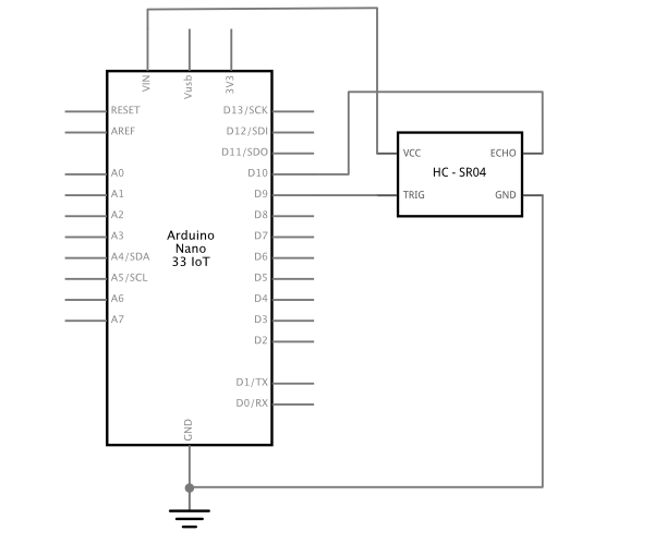
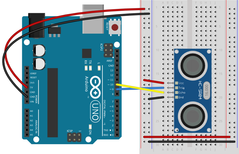
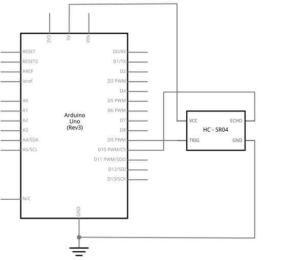
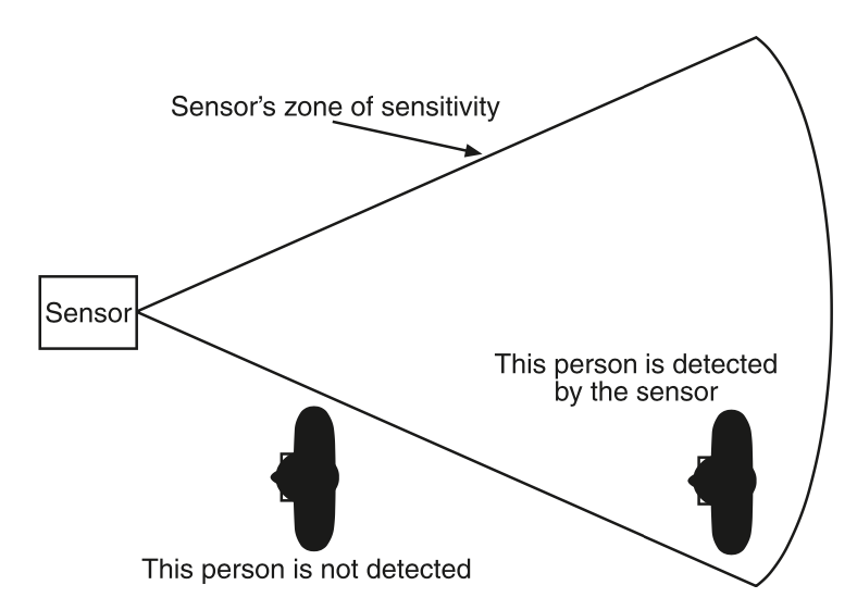
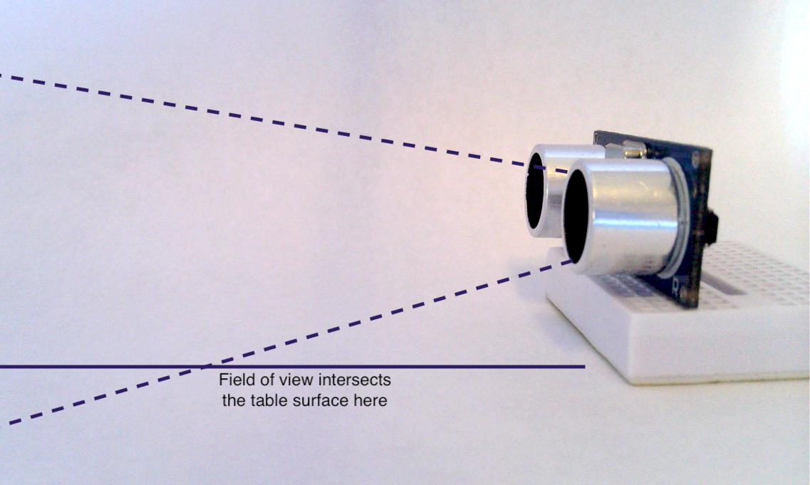


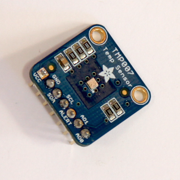
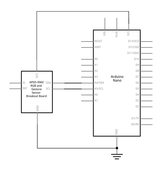
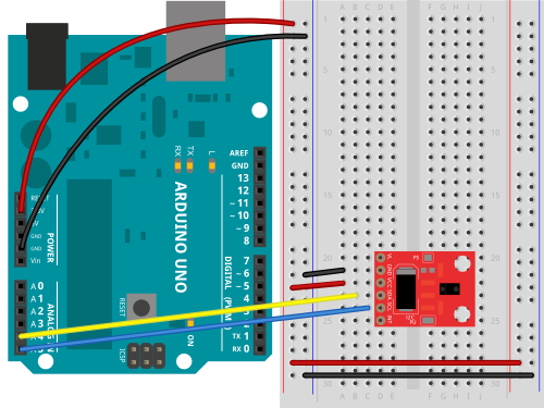
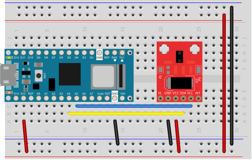
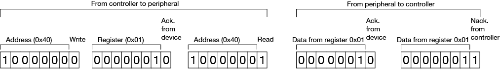
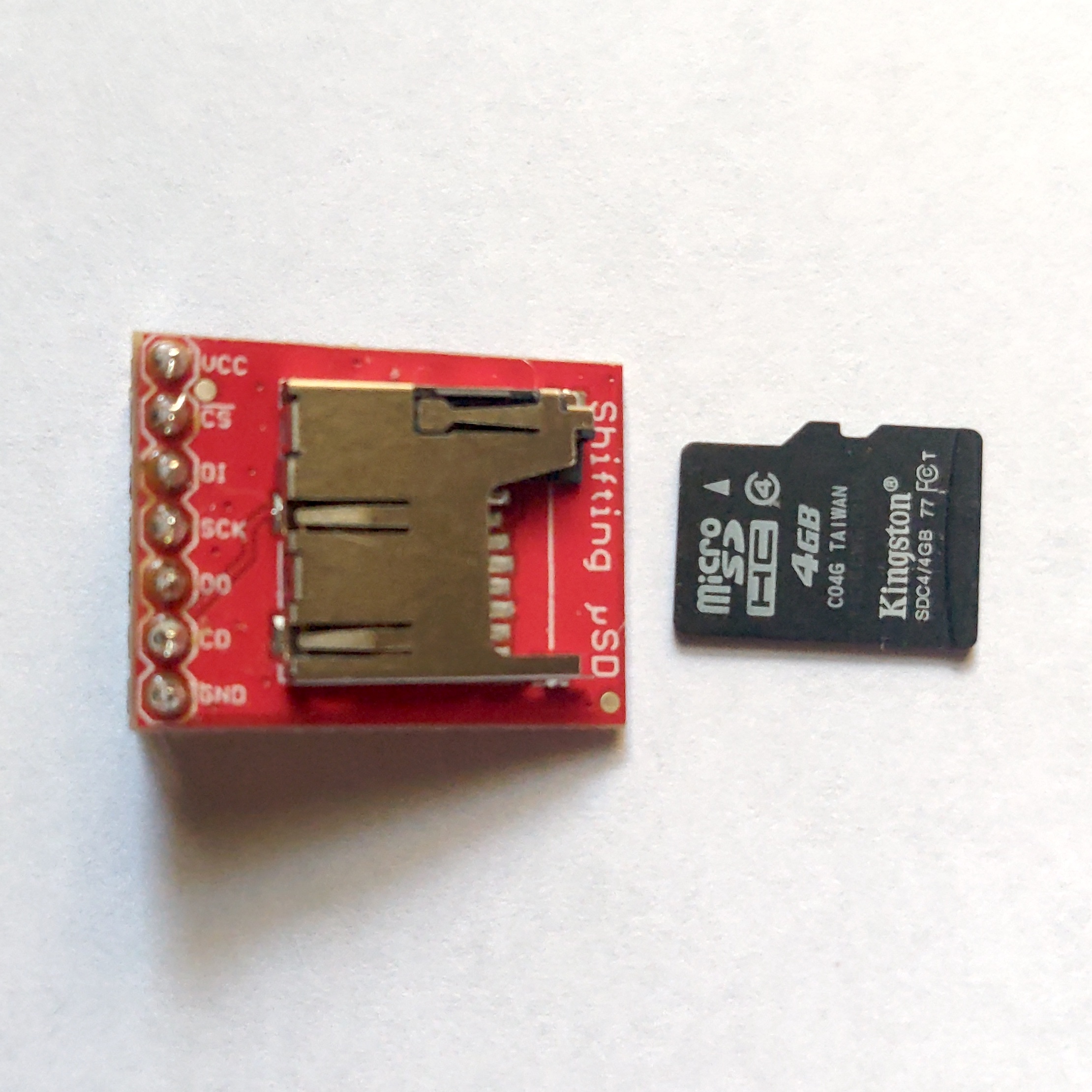

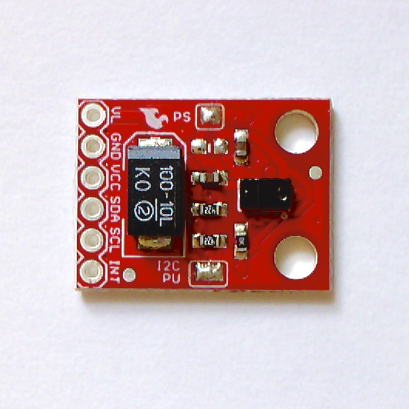

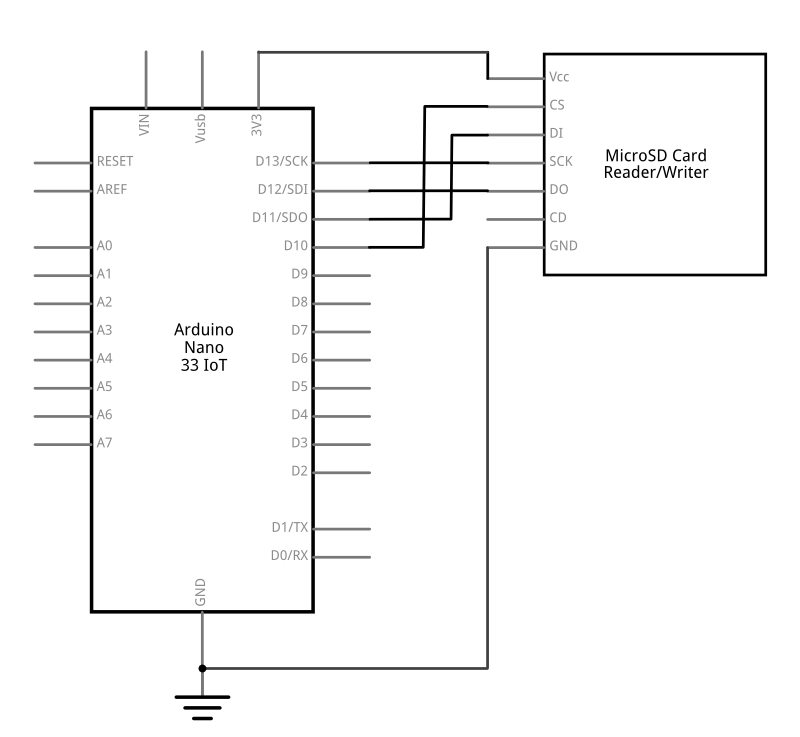
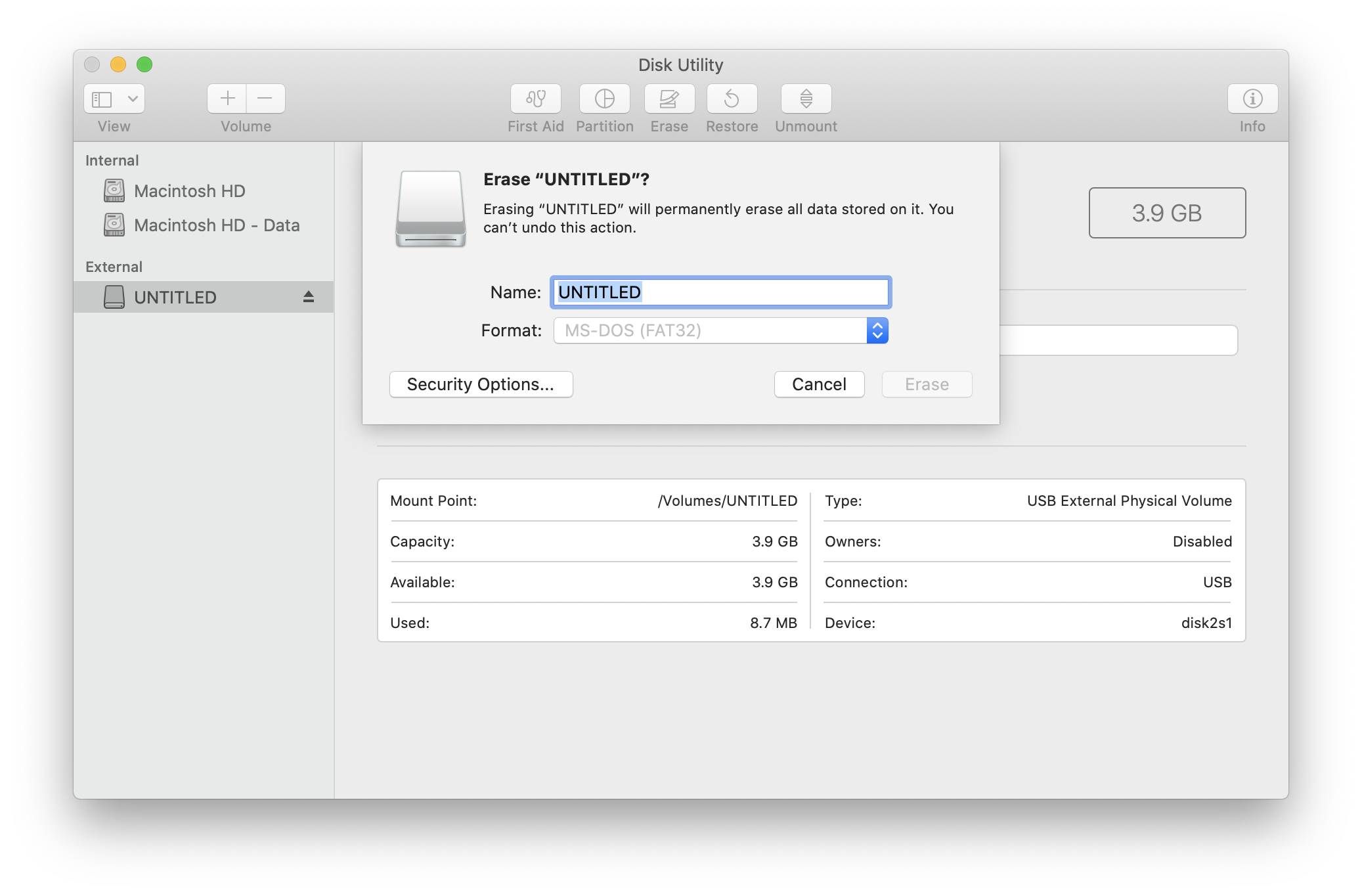
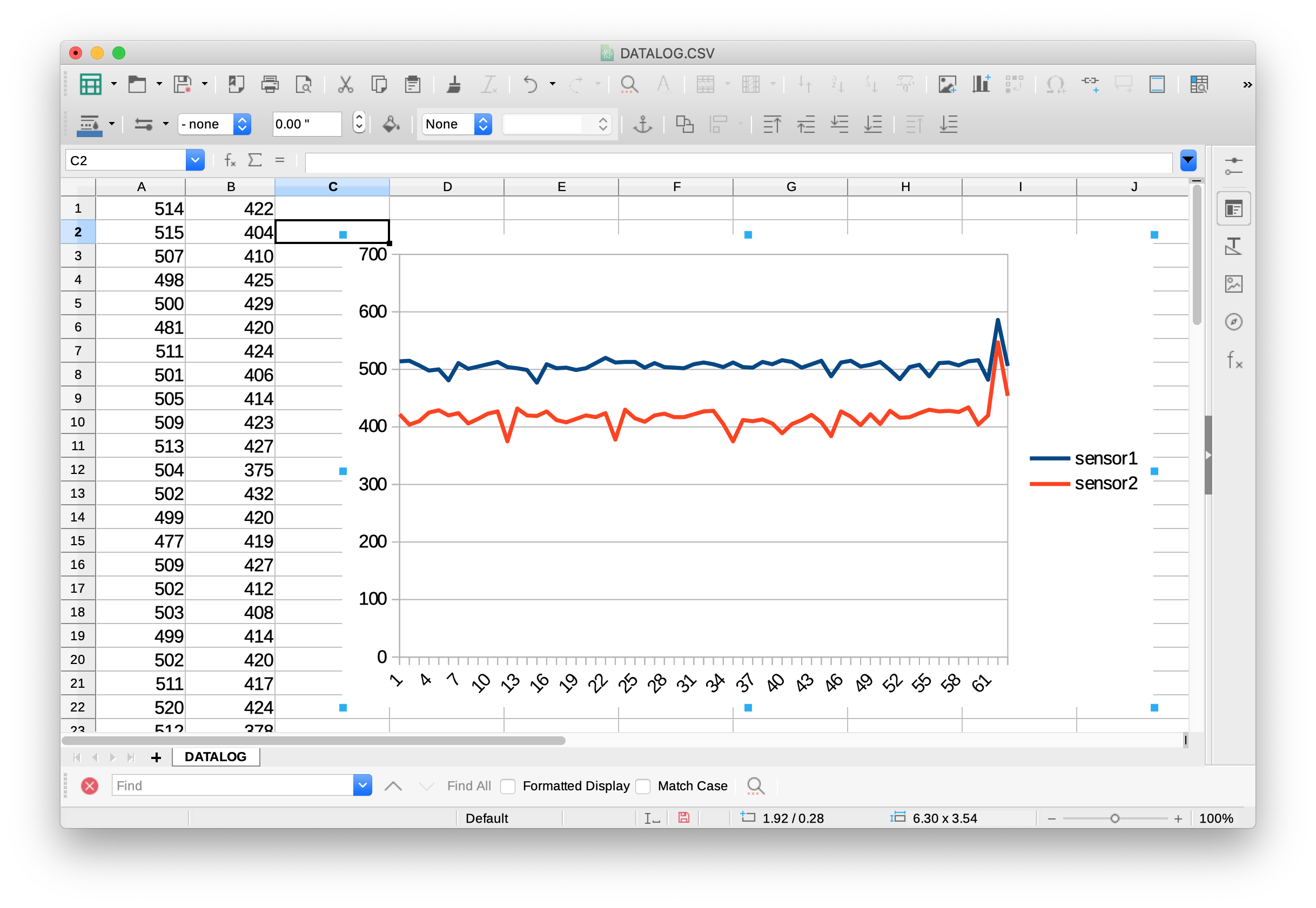
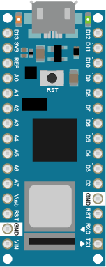

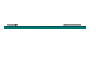
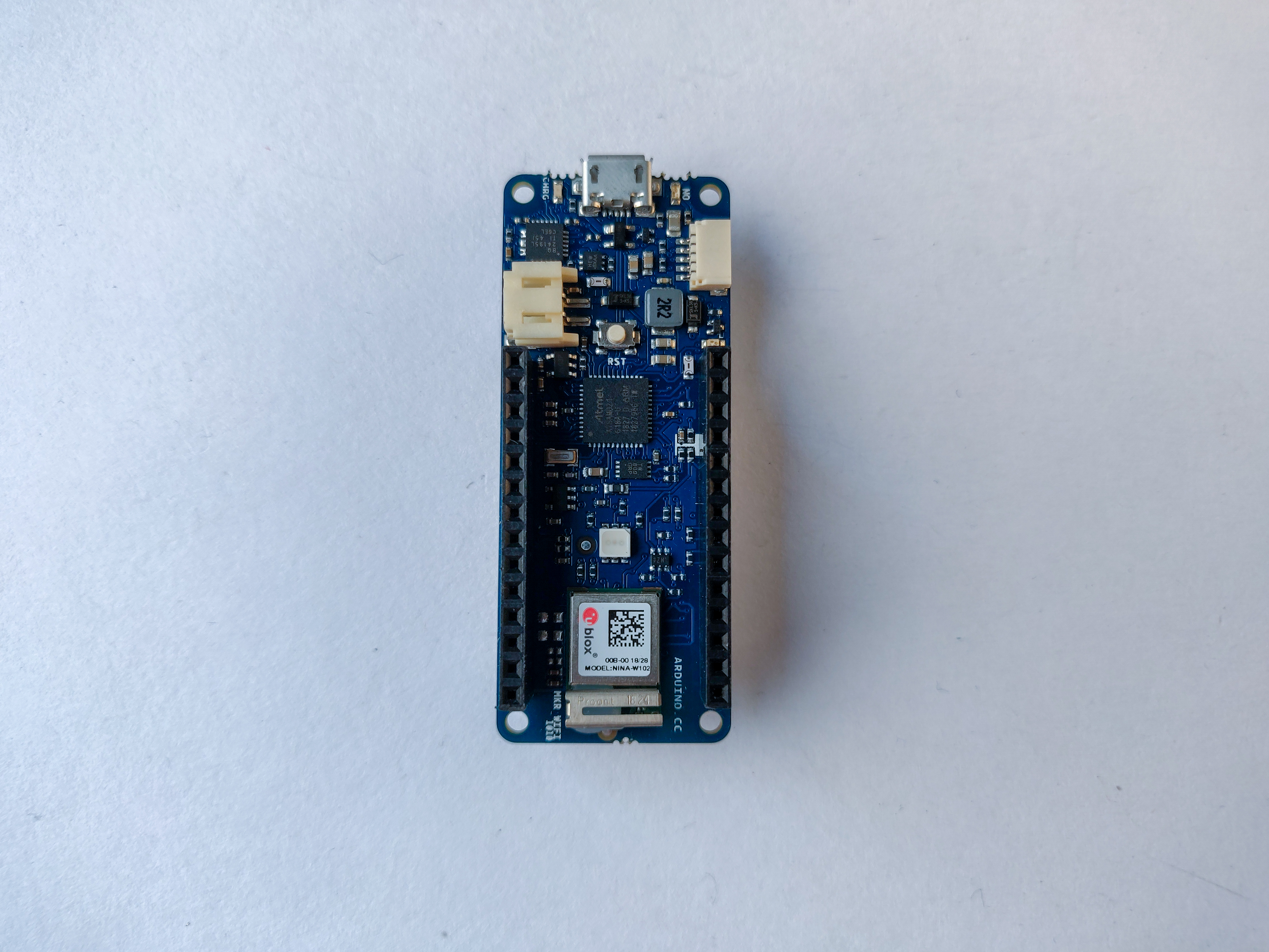
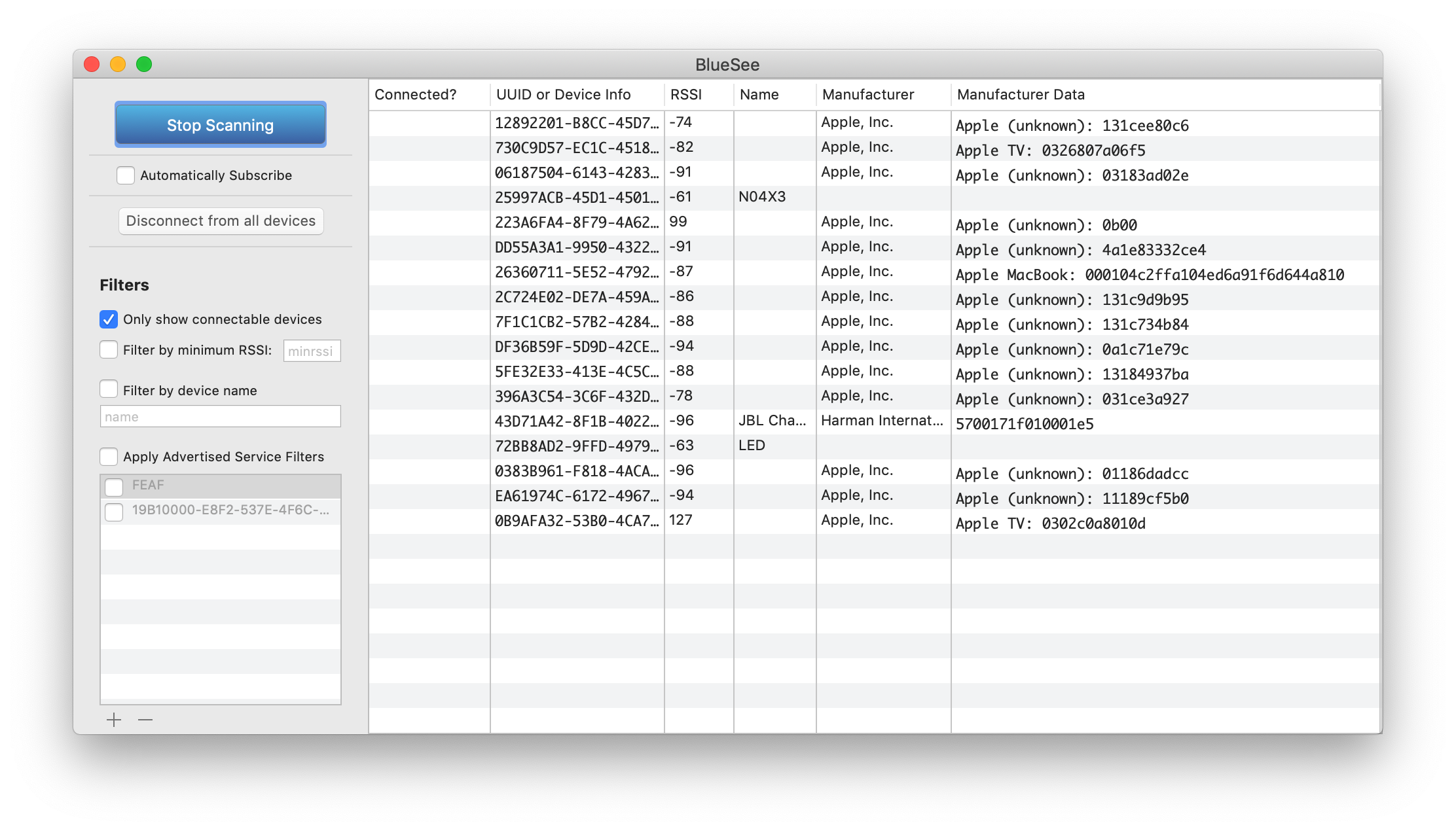
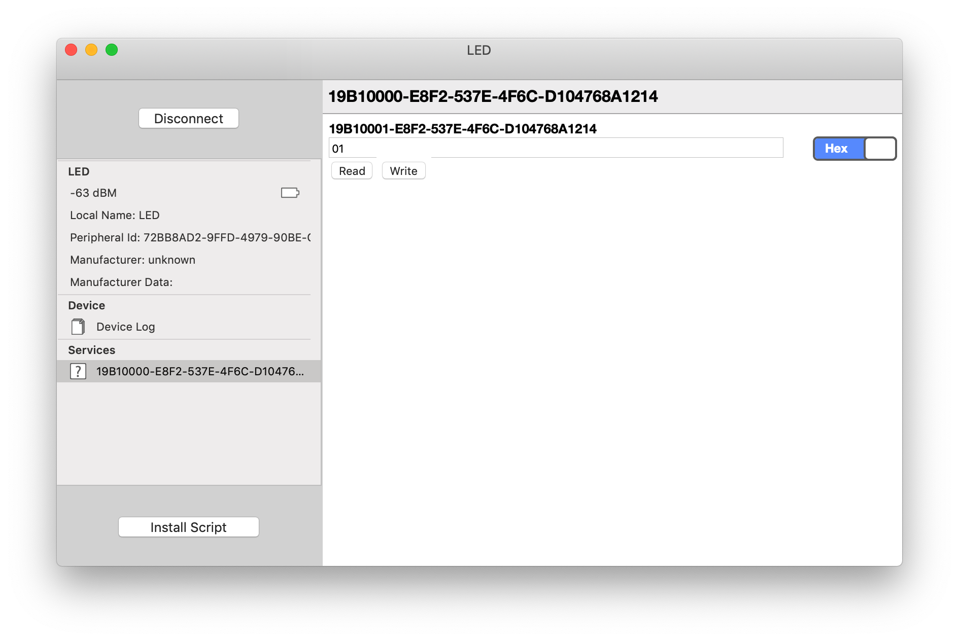
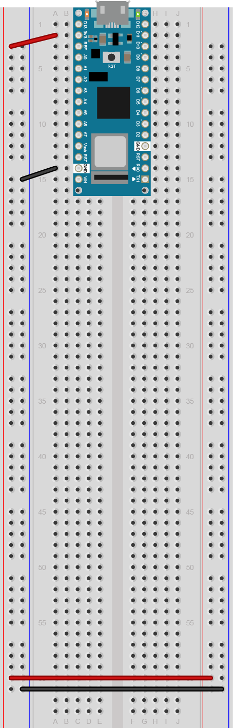

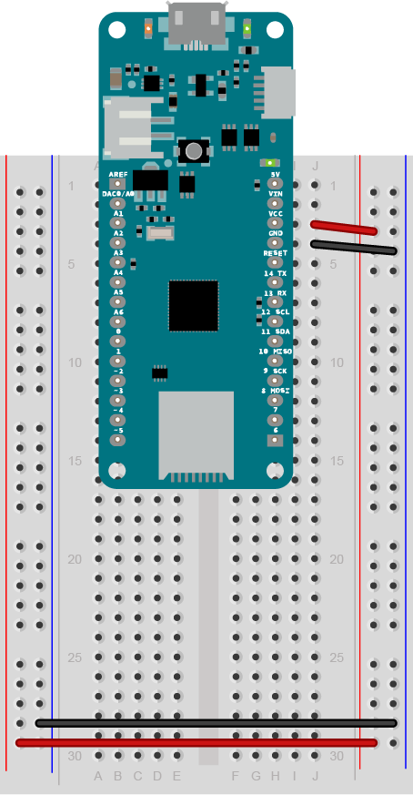

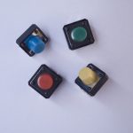

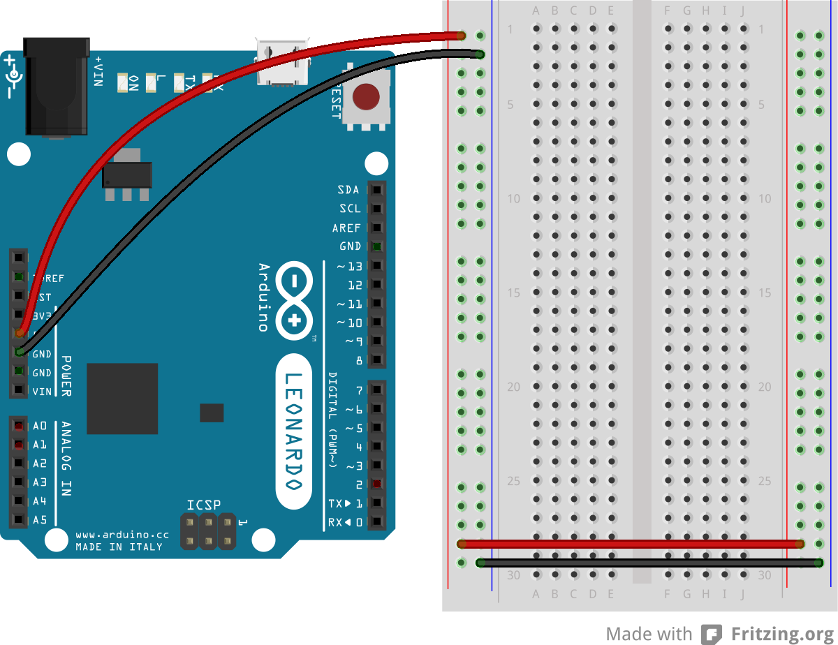
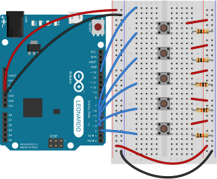
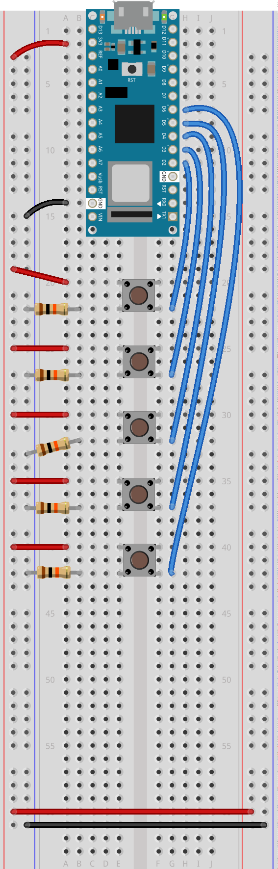
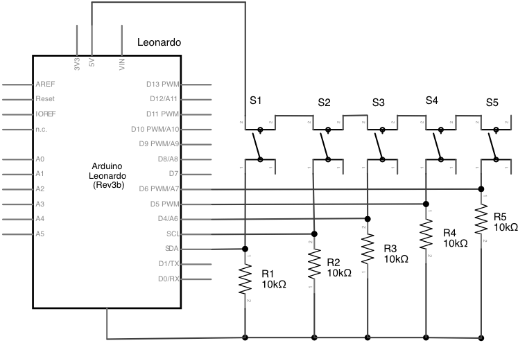
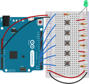
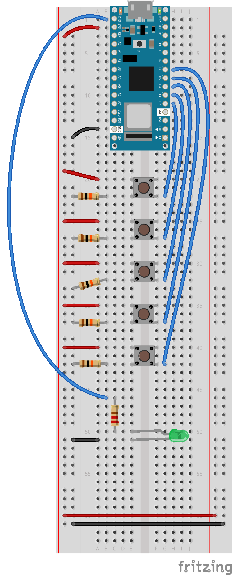
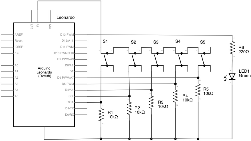
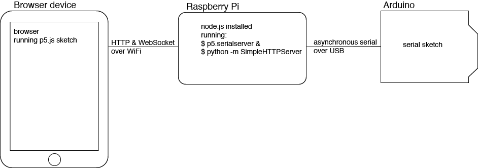
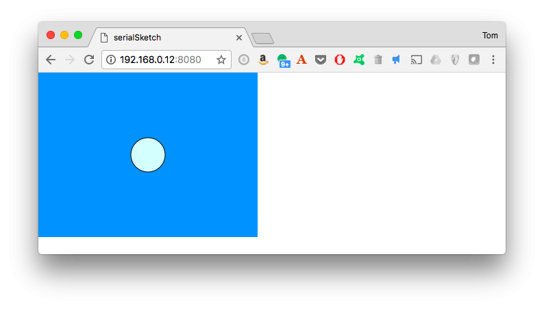
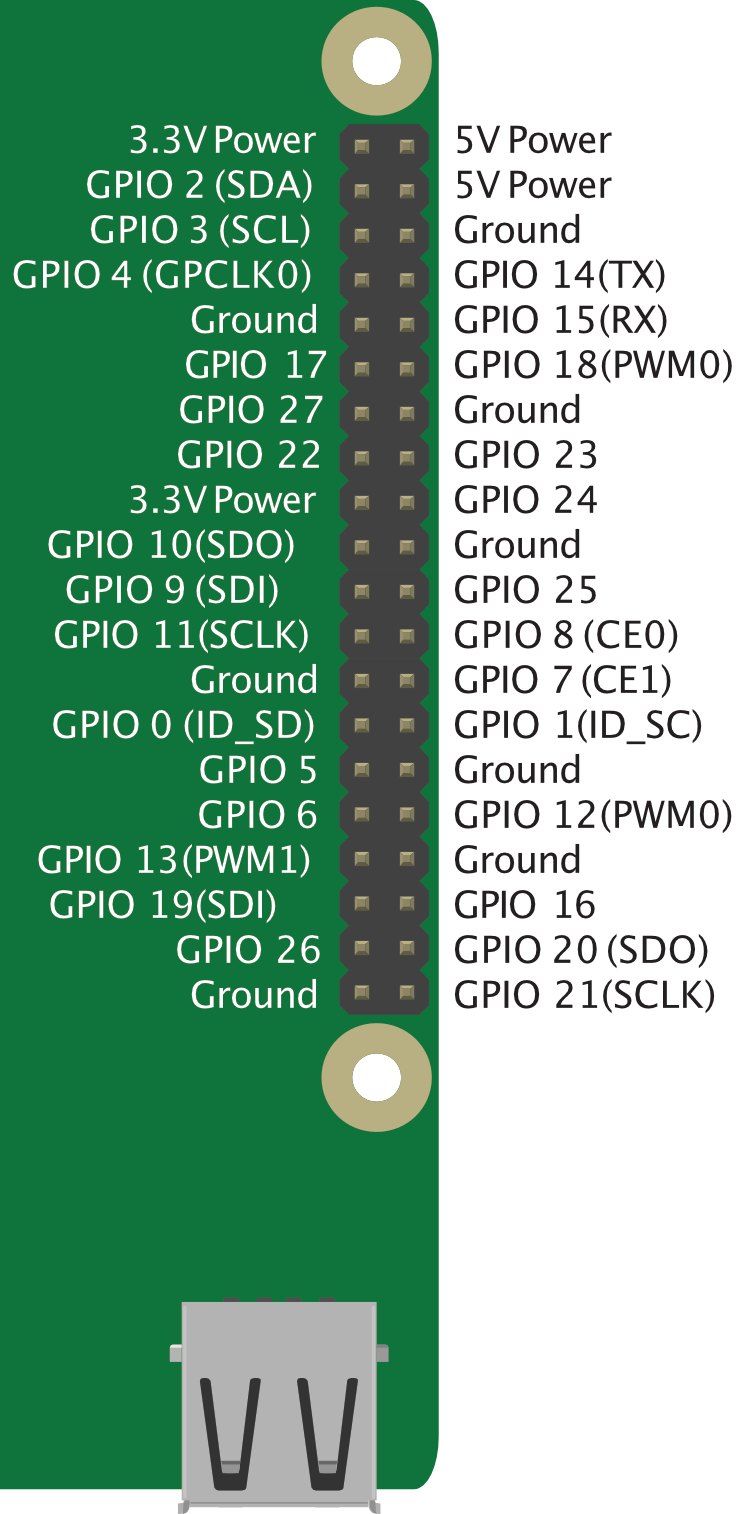
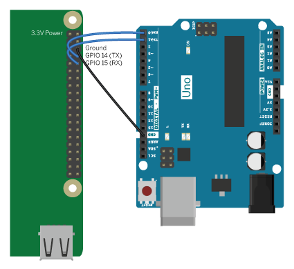
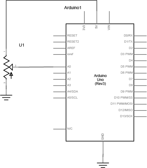
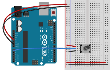